

Page 1
Technical Information
Orbital Motors
General
www.danfoss.com
Page 2

Technical Information
General, Orbital Motors
Revision history Table of revisions
Date Changed Rev
December 2021 Comprehensive catalogue update 0401
July 2018 updated to Engineering Tomorrow design 0203
June 2015 Minimum speed updated 0202
May 2015 Motor version removed from section 'Motors woth integrated flushing valve CB
November 2014 Converted to Danfoss layout - DITA CMS CA
June 2005 BA
Changed document number from 'BC00000083' and '520L0232' to 'BC152886483554' 0301
2 | © Danfoss | December 2021 BC152886483554en-000401
Page 3

Technical Information
General, Orbital Motors
Contents
A wide range of Orbital Motors
Conversion Factors
Orbital Motors, General
Selection of Motor Type
Selection of Motor Size
Bearing Dimensioning
Hydraulic Systems
Orbital Motors Introduction......................................................................................................................................................... 5
Orbital Motors Features............................................................................................................................................................5
Technical Features......................................................................................................................................................................5
Orbital Motors Application Areas..........................................................................................................................................5
Orbital Motors Literature Overview...........................................................................................................................................6
Operating Principle..........................................................................................................................................................................8
Gearwheel set...............................................................................................................................................................................8
Distributor valve..........................................................................................................................................................................8
Disc valve with valve drive................................................................................................................................................. 8
Features of main types................................................................................................................................................................... 9
OMT, OMV......................................................................................................................................................................................9
TMT...................................................................................................................................................................................................9
Motor Variants................................................................................................................................................................................... 9
Wheel motor................................................................................................................................................................................. 9
Short motors...............................................................................................................................................................................10
Ultrashort motor....................................................................................................................................................................... 10
Motors with integrated negative holding brake...........................................................................................................10
Motors with integrated flushing valve..............................................................................................................................11
Motors with tacho connection............................................................................................................................................ 11
Motors with speed sensor..................................................................................................................................................... 12
Build-up of the Function Diagram...........................................................................................................................................13
Continuous operation/intermittent operation/peak load.........................................................................................13
Efficiency......................................................................................................................................................................................14
Volumetric efficiency...............................................................................................................................................................14
Example........................................................................................................................................................................................14
Hydraulic mechanical efficiency..........................................................................................................................................15
Example:.......................................................................................................................................................................................15
Total efficiency...........................................................................................................................................................................16
Minimum speed..............................................................................................................................................................................16
Shaft load and bearing life time............................................................................................................................................... 17
Relationship between Bearing Life Time and Speed........................................................................................................ 17
Relationship between Shaft Load and Bearing Life Time................................................................................................17
Relationship between permissible shaft load and speed............................................................................................... 18
Maximum Radial Shaft Load...................................................................................................................................................... 18
Max. Pressure on the Shaft Seal................................................................................................................................................19
Standard shaft seal (NBR).......................................................................................................................................................19
High-pressure shaft seal (NBR).............................................................................................................................................19
Viton shaft seal (FPM)..............................................................................................................................................................19
Characteristics of sealing materials....................................................................................................................................19
Short/ultra-short motors........................................................................................................................................................20
Drain Line..........................................................................................................................................................................................20
Application..................................................................................................................................................................................20
Oil flow in the drain line......................................................................................................................................................... 20
Braking...............................................................................................................................................................................................20
Braking torque...........................................................................................................................................................................21
Opening pressure for the dual shock valve.....................................................................................................................21
Replenishment...........................................................................................................................................................................21
Seeping.........................................................................................................................................................................................23
Brake Motors....................................................................................................................................................................................23
©
Danfoss | December 2021 BC152886483554en-000401 | 3
Page 4

Technical Information
General, Orbital Motors
Contents
OMT FX, OMT FL and TMT FL................................................................................................................................................24
OMT FH.........................................................................................................................................................................................24
Installation, Starting Up, Maintenance and Oil Types.......................................................................................................25
Design in brief............................................................................................................................................................................25
Combination in brief............................................................................................................................................................... 25
Starting up and running in the hydraulic system......................................................................................................... 25
Signs of air in the hydraulic system....................................................................................................................................26
If there is air in the system.....................................................................................................................................................26
During operation...................................................................................................................................................................... 26
Maintenance...............................................................................................................................................................................26
Oil Types.......................................................................................................................................................................................26
Mineral oils.............................................................................................................................................................................26
Non-flammable or biodegradable fluids....................................................................................................................26
Temperature, Viscosity and Filtering...................................................................................................................................... 27
Temperature...............................................................................................................................................................................27
Viscosity........................................................................................................................................................................................27
Filtering........................................................................................................................................................................................ 28
4 | © Danfoss | December 2021 BC152886483554en-000401
Page 5

Technical Information
General, Orbital Motors
A wide range of Orbital Motors
Orbital Motors Introduction
Danfoss is a world leader within production of low speed orbital motors with high torque. We can offer
more than 1500 different orbital motors, categorized in types, variants and sizes (including different shaft
versions).
The motors size vary (rated displacement) from 130 to 800 cm3 [7.9 to 48.9 in3] per revolution.
•
Speeds range up to approximate 600 min-1 (rpm).
Maximum operating torques up to 3400 N•m [30090 lb•in] (peak) and maximum outputs up to 70 kW [95
hp].
Orbital Motors Features
•
•
•
•
•
•
•
•
•
•
Motor sizes:
OMT and OMV
‒
TMK
‒
TMT
‒
TMTHW
‒
TMVW
‒
Smooth running over the entire speed range
Constant operating torque over a wide speed range
High starting torque
High return pressure without the use of drain line (high pressure shaft seal)
High efficiency
High radial and axial bearing capacity
Long life under extreme operating conditions
Robust and compact design
For applications in both open and closed loop hydraulic systems
Suitable for a wide variety of hydraulics fluids
Technical Features
The program is characterized by technical features appealing to a large number of applications and by
motors that can be adapted to a given application.
Adaptions comprise the following variants:
Motors with:
•
integrated negative holding brake
‒
speed sensor
‒
black finish paint
‒
Short motors without bearings or Ultra short motors
•
Wheel motors with recessed mounting flange
•
Orbital Motors Application Areas
The orbital motors are used in the following application areas:
Construction equipment
•
Agricultural equipment
•
Material handling & Lifting equipment
•
Forestry equipment
•
Lawn and turf equipment
•
©
Danfoss | December 2021 BC152886483554en-000401 | 5
Page 6

Technical Information
General, Orbital Motors
A wide range of Orbital Motors
Machine tools and stationary equipment
•
Marine equipment
•
Special purpose
•
Orbital Motors Literature Overview
A general catalog of all Orbital Motors with technical data gives a quick motor reference based on:
selection of orbital motor, function in hydraulic systems, power, torque, speed and capabilities. More
detailed information can be found in an individual motor catalogs.
Literature title Literature type Reference number
Orbital Motors in General Technical Information BC152886483554
OMT and OMV Orbital Motors Technical Information BC152886483862
TMK, TMKW, TMK FL Orbital Motors Technical Information BC152886483785
TMT, TMTU, TMTW, TMT FL Orbital Motors Technical Information BC152886483631
TMTHW Orbital Motors Technical Information BC152986483537
6 | © Danfoss | December 2021 BC152886483554en-000401
Page 7

Technical Information
General, Orbital Motors
Conversion Factors
1 Nm = [8.851 lbf.in]
1 cm3 = [0.061 in3]
1 N = [0.2248 lbf ]
1 l = [0.22 UK gal]
1 bar = [14.50 psi]
1 l = [0.264 US gal]
1 mm = [0.0394 in]
°F = [1.8 °C + 32]
©
Danfoss | December 2021 BC152886483554en-000401 | 7
Page 8
151-1053.10
A
B
C
D
E
F
Technical Information
General, Orbital Motors
Orbital Motors, General
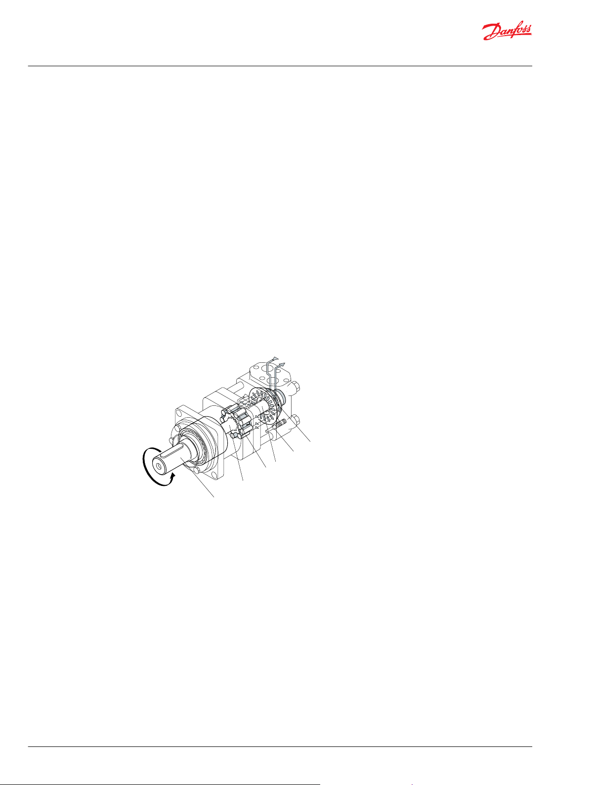
Operating Principle
Orbital motors convert hydraulic energy (pressure, oil flow) into mechanical energy (torque and speed).
Danfoss orbital motors are of fixed displacement high-torque design. For a given oil flow and given
pressure the displacement (size of motor) determines the speed and torque. For a given displacement
(size of motor) the speed is determined by the oil flow rate and the torque is determined by the pressure
differential.
Gearwheel set
The operating principle of the motors is based on an internal gear design, consisting of a fixed external
gear reaching against an internal gear through which the output torque and speed are transmitted.
Distributor valve
The distributor valve is driven synchronously by the internal gear through a cardan shaft ensuring that
the individual chambers of the motor are filled and emptied precisely - without losses.
Disc valve with valve drive
OMT, OMV and TMT motors have a disc valve: The distributor valve has been separated from the output
shaft and it is driven by a short cardan shaft [valve drive]. A balance plate counterbal-ances the hydraulic
forces around the distributor valve.
A: Output shaft D: Valve drive
B: Cardan shaft E: Check valve
C: Gearwheel set F: Disc valve
8 | © Danfoss | December 2021 BC152886483554en-000401
Page 9
151-1374.10
151-887.10
151-1056.10
Technical Information
General, Orbital Motors
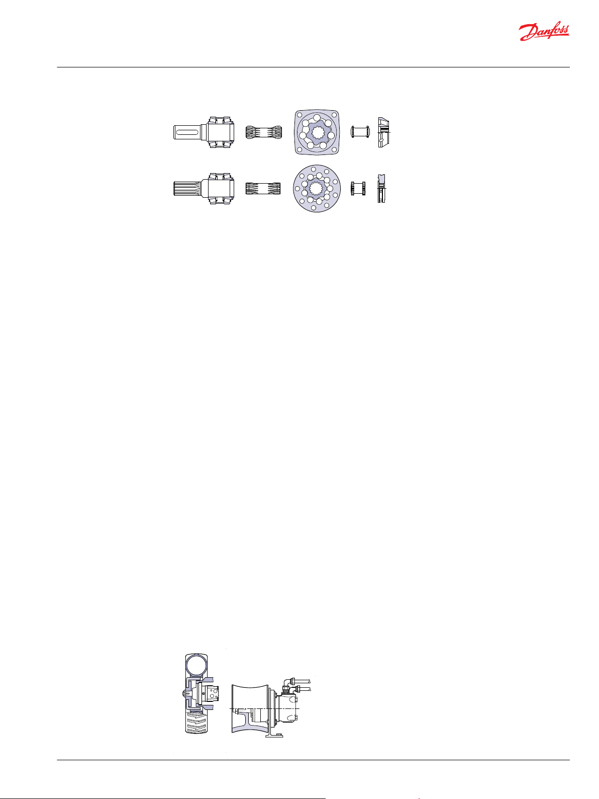
Selection of Motor Type
Features of main types
OMT, OMV
Gear rim with rollers
•
Disc valve with separate valve drive
•
Output shaft supported in tapered roller bearings
•
TMT
Gear rim with rollers
•
Disc valve with separate valve drive
•
Output shaft supported in tapered roller bearings
•
Motor Variants
OMT, OMV
OMT and OMV are suitable for continuous operation under rough operating conditions: e.g. high
pressures, thin oil, or frequent reversals. The tapered roller bearings make the motors suitable for
absorbing static and dynamic radial loads. Besides the separately driven and hydraulically balanced disc
valve, hydraulic and mechanical losses are reduced to a minimum. This gives the motors high efficiency even at high pressures, and good starting characteristics.
TMT
The marked for hydraulic motors has developed generally increasing expectations of the motor
performance, and espacially of a higher pressure level. On some applications the present motor program
no longer fulfils the marked demand. The TMT motors comply with these expectations providing the
same good characteristics as the OMT and OMV motors.
If the application requires very smooth running at low speeds the choice of OMT, OMV or TMT is
recommended.
Wheel motor
OMT and OMV motors are available in wheel motor versions. The recessed mounting flange makes it
possible to fit a wheel hub or a winch drum so that the radial load acts midway between the two motor
bearings. This gives the best utilisation of the bearing capacity and is a very compact solution. Type
designations of wheel motors are OMTW and OMVW.
©
Danfoss | December 2021 BC152886483554en-000401 | 9
Page 10

151-977.10
151-1691.10
Technical Information
General, Orbital Motors
Selection of Motor Type
Short motors
OMT and OMV motors are available in short versions. It can be an advantage to use a short motor for
gears that already have the capacity to absorb radial and axial forces.
Type designations are OMTS and OMVS.
Ultrashort motor
OMT, OMV and TMT are available with ultrashort installation dimensions, i.e. without bearings and output
shaft. The ultrashort design allows an opti-mised integration of the motor in the counterpart. Special
installation conditions please contact the Danfoss Sales Organisation.
Type designations: OMTU, OMVU and TMTU.
Motors with integrated negative holding brake
OMT and TMT with integrated multi-disc brake is available in four versions:
OMT FH, OMT FL, OMT FX and TMT FL. The brake is a spring activated multi-disc type that is released by a
hydraulic pressure. OMT FH can work with high drop pressure [e.g. piloted from a shuttle valve in open
loop systems], whereas OMT FL, OMT FX and TMT FL release the brake at low pressure [e.g. piloted from
the charge pump in closed loop systems]. OMT FX are particularly well-suited for applications that require
very short installation dimensions, - for example in road rollers and wheels.
The design of the OMT F and TMT F motors allows the brake to be used as dynamic emergency brake as
well.
10 | © Danfoss | December 2021 BC152886483554en-000401
Page 11

151-1425.10
151-1627.10
A B
151-1372.10
Technical Information
General, Orbital Motors
Selection of Motor Type
Motors with integrated flushing valve
Without any change to their outer dimensions, OMT, OMV and TMT are available with an integrated
flushing valve.
The integrated flushing valve ensures continuous renewal and cooling of the oil in the closed circuit. The
flushing valve is activated by the high pressure side of the motor and allows the flushing flow to pass to
the drain line and the tank.
Type designation: OMT V, OMV V and TMT V .
Motors with tacho connection
OMT and OMV motors are available in a version with tacho drive shaft. With a tacho connection the
speed of the motor can be registered.
Type designations are OMT T and OMV T.
©
Danfoss | December 2021 BC152886483554en-000401 | 11
Page 12

151-1569.10
Technical Information
General, Orbital Motors
Selection of Motor Type
Motors with speed sensor
OMT and OMV are available with integrated speed sensor. The electric output signal is a standardized
voltage signal that may for example be used with Danfoss' electronic module type EHSC to control the
speed of the motor. The speed is registered by an inductive sensor.
Signal processing and amplification are integrated in the housing of the sensor.
Type designation: OM - EM.
12 | © Danfoss | December 2021 BC152886483554en-000401
Page 13

Technical Information
General, Orbital Motors
Selection of Motor Size
When a certain motor type has been selected in accordance with the requirements of the individual
application, the size of the motor is determined according to the torque and speed required for the
application.
For this purpose use the bar chart on the first pages of the subcatalogues and the function diagram for
the individual motor.
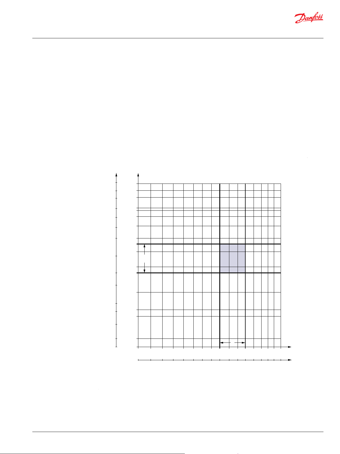
Build-up of the Function Diagram
The function diagram for a hydraulic motor shows the relation between operating torque M (vertical axis)
and speed n (horizontal axis) at different pressure drops ∆p and oil flows Q.
The curves for constant pressure drop and constant oil flow form a network superimposed on the
coordinate system grid. The curves for constant power output N (hyperbolas] and constant total
efficiency ηt are also plotted. The latter curves have a ring form, to as on mussel shells. For this reason
function diagrams are often called shell diagrams.
OMT 160 function diagram
Continuous operation/intermittent operation/peak load
The function diagrams are divided up into a blue area A and two red areas B.
The blue area A represents the continuous range of the motor. Within this range the motor is able to run
continuously with optimum efficiency and operating life.
The two red areas B represent the intermittent range of the motor. It is advantageous to make use of the
intermittent range when the motor works with varying loads, but also to allow for braking torques when
reversing direction.
It is permissible to subject the motor to intermittent speed or intermittent pressure drop for max. 10% of
every minute. The motor should not be subjected to intermittend speed and intermitend pressure drop
at the same time.
The upper limits for intermittent pressure drop and torque must not be exceeded for more than 1% of
every minute (peak load). The max. peak load value is stated in the technical data for each type of motor.
High pressure peaks occur, for example, when a pressure relief valve opens or a directional valve is
opened or closed. Pressure relief valves and dual shock valves should be set so that pressure peaks do not
exceed the max. peak values. In systems with large pressure oscillations the pressure and torque peaks
should be measured with electronic equipment.
©
Danfoss | December 2021 BC152886483554en-000401 | 13
Page 14

4071 460
Nm
in•lbs
151-247.10
80 l/min
[21.1 US gal/min]
460
min
-1
(rpm)
η
V
Q
1
Q
2
Q
3
Q1 = Q
total
Q2 = Q
theor*
Q3 = Q
leak
Technical Information
General, Orbital Motors
Selection of Motor Size
To give problem-free operation the motor size should be selected using the permissible continuous and
intermittent values while making sure that pressure peaks do not exceed the max. peak values.
Efficiency
The total efficiency ηt is the product of the volumetric efficiency (ηv) and the hydraulic-mechanical
efficiency (ηhm). Thus ηt = ηv x ηhm.
Volumetric efficiency
The volumetric efficiency is an expression for the proportion of the applied quantity of oil [as a
percentage] that is converted to output shaft revolutions (speed). The remaining quantity of oil (leakage)
is led across clearances and sealing surfaces to act as a lubricant/coolant.
When the load (pressure drop) increases, leakage also increases.
The quantity of oil supplied to the gearwheel set thus diminishes, and the number of revolution (speed)
falls.
The slope of the Q-curve expresses the magnitude of the efficiency
Example
An OMT 160 is to drive a shaft at a speed of 460 min-1 (rpm) with an applied torque of 460 Nm [4071
lbf•in].
If the volumetric efficiency was 100% the oil quantity would be the geometric displacement times the
number of revolutions.
Theoretical supplied oil quantity:
However, the actual supplied oil quantity is 50 l/min [13.2 US gal]. The volumetric efficiency can be
calculated as follows:
14 | © Danfoss | December 2021 BC152886483554en-000401
Page 15

4539
4071
3009
513
460
340
Nm
in•lbs
200 bar
2900 psi
151-248.10
460
min
-1
(rpm)
η
h
η
m
Technical Information
General, Orbital Motors
Selection of Motor Size
Hydraulic mechanical efficiency
The hydraulic mechanical efficiency is an expression for the proportion of applied pressure (as a
percentage) that is converted to output shaft torque.
The remaining pressure is loss; either mechanical loss at low speeds or hydraulic loss at high speeds, as
can be seen on the torque graph (pressure-drop curve). Mechanical loss is greatest at motor start-up
because a film of lubricant has not yet been built up on moving parts. After a few revolutions the film is
established and friction is reduced (the curve steepens). Hydraulic loss is greatest at high speeds because
of the high pressure losses in ports and oil channels when oil flow is high. Therefore the pressure drop
across the gearwheel set becomes less and the motor yields less torque.
OMT 160 has a minimum starting torque of 340 Nm [3009 lbf•in] at a pressure drop of 200 bar [2900 psi],
as given in the OMT technical data table. When the lubricant film is established, the motor yields 460 Nm
[4071 lbf•in] with the same pressure drop.
On the function diagram the pressure drop curve does not intersect the torque axis, but min. starting
torque at max. continuous and max. intermittent pressure drop is given in the technical data for each
motor type.
Example:
To calculate the hydraulic-mechanical efficiency ηhm, it is necessary to first read off (measure) the motor
torque Tmot eff for a given oil flow and given pressure drop. The function diagram efficiency graphs show
that an OMT 160 gives a torque of 460 Nm [4071 lbf•in] for a pressure drop of 200 bar [2900 psi] and an oil
flow of 80 l/min [21.1 US gal/min].
The theoretical motor torque for the same pressure drop can be calculated as follows:
©
Danfoss | December 2021 BC152886483554en-000401 | 15
Page 16

Technical Information
General, Orbital Motors
Selection of Motor Size
Dividing the read-off (measured) torque by the theoretical torque gives the hydraulic-mechanical
efficiency:
Total efficiency
It is now possible to calculate the total efficiency of OMT 160 at ∆p = 200 bar [2900 psi] and Q = 80 l/min
[21.1 US gal/min]:
Minimum speed
With an acceptable degree of accuracy the same total efficiency can be read from the function diagram
efficiency graphs.
At very low speeds, the motors may run less smoothly. In borderline cases a motor of the desired type
should be tested under the required operating conditions in the system concerned before finally
selecting the motor size and type.
To obtain smooth running at very low speed the motor leakage must be constant. Therefore it is
recommended that a motor with disc valve (OMT, OMV or TMT) be chosen, but avoid choosing motors
with the smaller displacements. The best results are achieved with a constant load, a return pressure of
3-5 bar [45-70 psi] and an oil viscosity of min. 35 mm2/s [164 SUS].
16 | © Danfoss | December 2021 BC152886483554en-000401
Page 17

151-1055.10
n
P
ax.
P
rad.
Technical Information
General, Orbital Motors
Bearing Dimensioning
Shaft load and bearing life time
In many applications the hydraulic motors must absorb both
•
•
For such applications hydraulic motors with built-in rolling bearings are particularly suitable. Two
different types of bearing are used in Danfoss hydraulic motors:
The largest possible bearing capacity for the individual motor type is obtained by using OMTW or OMVW,
because the recessed mounting flange makes it possible to fit for example wheel hubs and winch drums
so that the radial load is applied centrally to the two bearings.
Motor with tapered roller bearings
external radial and axial forces acting directly on the output shaft of the motor (e.g. from the weight
of a vehicle)
radial forces produced by torque transfer from gearwheels, chainwheels, V-belts or winch drums.
1. Needle bearings in WPN. The needle bearings are capable of absorbing large radial forces. As the
motors have separate axial bearings, the operating life of the needle bearings is not affected by the
size of the axial load.
2. Tapered roller bearings in OMT, OMTW, OMV, OMVW and TMT. The tapered roller bearings can absorb
large radial and axial forces.
Relationship between Bearing Life Time and Speed
It is a general rule that life time and speed are inversely proportional: life is doubled when speed is
halved. So life can easily be calculated for other speeds than those given in the sections on shaft load in
the individual subcatalogues.
The relation is expressed by the formula:
L
= L
x (n
/ n
new
ref
ref
where L
the subcatalogue.
is the life time at speed n
new
new
)
new
, and L
and n
ref
are the data for the given motor type found in
ref
Relationship between Shaft Load and Bearing Life Time
Lower shaft loads result in longer life time of the bearings. The exact relationship is shown by the
following formula:
©
Danfoss | December 2021 BC152886483554en-000401 | 17
Page 18

Technical Information
General, Orbital Motors
Bearing Dimensioning
L
is the bearing life at a shaft load of P
new
Relationship between permissible shaft load and speed
In certain applications the motor must run at low speeds while the bearings must absorb high loads. This
is the case for example when the motors are vehicle support elements. In such cases the following
relationship between speed and bearing load (with unchanged bearing life time) must be taken into
account:
P
is the shaft load at n
new
For n
= 200 min-1 [rpm] we have the following table for
ref
P
/ P
new
n
P
:
ref
/ min-1 (rpm) 25 50 100 200 300 400 500 600 700
new
/ P
new
ref
new
1.88 1.52 1.23 1.00 0.88 0.81 0.75 0.72 0.68
. P
and n
ref
, and L
new
are data from the subcatalogue.
ref
ref
and n
are data from the subcatalogue.
ref
Maximum Radial Shaft Load
The calculations above are solely for bearing life time and load capacity. But there is also a limit to how
much load the other parts of the motor (bearing housing, mounting flange and output shaft) can carry.
For this reason the maximum shaft load is limited to avoid the risk of mechanical breakdown.
The maximum shaft load is shown in the shaft load diagrams for OMT, OMV and TMT motors.
Please contact the Danfoss sales organisation for hydraulics if motors are to be subjected to shaft loads
higher than the maximum, or where there are particularly high dynamic effects (shock factor > 3).
18 | © Danfoss | December 2021 BC152886483554en-000401
Page 19

151-1803.10
151-1807.10
Technical Information
General, Orbital Motors
Hydraulic Systems
Max. Pressure on the Shaft Seal
Danfoss hydraulic motors can be supplied fitted with one of three different shaft seals:
Standard shaft seal (NBR)
The standard shaft seal in Danfoss hydraulic motors has a long operating life and even under extreme
conditions retains its sealing capability. With optimal lip design, the shaft seal withstands both high
pressures and high speeds.
High-pressure shaft seal (NBR)
The high-pressure shaft seal (HPS) is a development of our standard shaft seal and the integrated backing
ring makes an external drain line superfluous in most operating conditions.
Viton shaft seal (FPM)
If a synthetic fluid is to be used in our hydraulic motors we recommend a Viton shaft seal.
Characteristics of sealing materials
Material Temperature ˚C [˚F] Remarks
NBR -30 to + 100
[-22 to 212]
FPM -30 to + 150
[-22 to 302]
Swells up on contact with most syntetic fluids
Can be used with Emulsions and Mineral oils
Ideal for mineral oil, synthetic fluids and
emulsions
All Danfoss motors, except the OMEW, are 3-cham-ber type of motors, i.e. this type og motor isolates the
high pressure from the case, which allows the use of an external drain when return line pressure is
excessive. These motors are offered with the following option:
Motors with check valve
The check valve means that the pressure on the shaft seal never exceeds the pressure in the return line. If
the motor contains check valves and there is no drain line, the motor return pressure must always be less
than or equal to the maximum permissible pressure on the shaft seal graph in the subcatalogue.
Motors with drain line
The drain line relieves the pressure on the shaft seal to tank. That is to say, the tank pressure must be less
than or equal to the max. permissible pressure on the shaft seal graph in the subcatalogue.
©
Danfoss | December 2021 BC152886483554en-000401 | 19
Page 20

151-1743.10
151-1743.10
Technical Information
General, Orbital Motors
Hydraulic Systems
Motors without check valve and drain line
The pressure on the shaft seal is equal to the average of the inlet pressure and return pressure:
P
= (P
seal
P
seal
subcatalogue.
Short/ultra-short motors
For these motors it is the values of the pressure on the shaft seal in connected component (e.g. a gear)
that applies.
+ P
inlet
must be less than or equal to the max. permissible pressure on the shaft seal graph in the
return
) / 2
Drain Line
Braking
Application
The drain line relieves pressure on the shaft seal to tank. The following main rules apply to drain lines
fitted to Danfoss hydraulic motors:
We recommend a drain line when the maximum pressure on the shaft seal is exceeded, i.e. the life of
•
the shaft seal can otherwise be significantly reduced.
We always recommend a drain line when
•
a short motor is built together with a gear.
‒
the motor is used in hydrostatic transmissions that do not have a separate flushing valve.
‒
Oil flow in the drain line
When the size of the supply pump in a closed hydraulic circuit is to be calculated, it is necessary to know
the maximum oil flow in the drain line. The maximum oil flow in the drain line for Danfoss hydraulic
motors is given in the technical data in the catalogue for each motor type.
Danfoss hydraulic motors are often used to brake a load. Here the motors operate as pumps that convert
the kinetic energy of the load (mass, speed) to hydraulic energy (oil flow, pressure). Examples of these
types of applications are:
Crane winches on vehicles
•
Net winches on fishing vessels
•
Top jib slewing on cranes and excavators
•
Hydrostatic transmissions
•
20 | © Danfoss | December 2021 BC152886483554en-000401
Page 21

Technical Information
General, Orbital Motors
Hydraulic Systems
The speed at which the load is braked is determined by the motor braking torque and the opening
pressure of the dual shock valve.
Braking torque
With a motor, the hydraulic-mechanical efficiency means that the effective torque is lower than the
theoretical torque.
T
motor eff
= T
theor
x ηhm (1)
With a pump, the hydraulic-mechanical efficiency means that the effective torque that must be applied
to the pump to create a given pressure drop is greater than the theoretical pressure drop.
T
pump eff
= T
theor
/ ηhm (2)
When a hydraulic motor is used as a pump (for braking) the ratio between braking torque and effective
motor output for a given pressure drop is as follows:
T
= T
/ ηhm (see 2) where
theor
= T
motor eff
= T
motor eff
/ ηhm (see 1)
2
/ (ηhm)
T
T
brake
theor
brake
We recommend the use of the following braking torques for Danfoss hydraulic motors:
OMT, OMV,TMT : T
•
brake
~ 1.2 · T
motor eff
.
T
can be read from the function diagram for the individual motor sizes.
motor eff
The braking torque must not be greater than the maximum motor operating torque.
The maximum torque is given in the technical data for each motor type.
Opening pressure for the dual shock valve
The braking torque can be regulated by setting the opening pressure of the dual shock valve. The
opening pressure should be set at max. oil flow, in that a 20-30% increase in opening pressure can be
expected when the oil flow is changed from minimum to maximum.
To avoid excessive pressure peaks, the dual shock valve should be rapid acting and be installed as close
to the hydraulic motor as possible.
Replenishment
When Danfoss hydraulic motors are used to brake a load, effective replenishment is necessary.
Inadequate replenishment can give rise to:
cavitation in the gearwheel set
•
insufficient braking capacity
•
There must therefore be positive charge pressure in the motor "suction" port.
The charge pressure (ps) must therefore be greater than the pressure drop in the motor oil channels
feeding the gearwheel set.
The pressure drop in the oil channels depends on the motor type, oil flow and oil viscosity. The pressure
drop graphs for each motor type are given in the respective catalogues.
The supply pressure should constitute half the pressure drop (pd) given on the graph:
ps = pd / 2
The charge pressure is always measured at the motor "suction" port.
In closed circuits the supply pressure will always be positive when the system is fitted with a charge
pump (ps ~ 10-15 bar [145-217 psi]).
In open systems where the hydraulic motor drives a load with high inertia, it is necessary to establish
replenishment as shown in fig. 1.
©
Danfoss | December 2021 BC152886483554en-000401 | 21
Page 22

151-122.10
Technical Information
General, Orbital Motors
Hydraulic Systems
The opening pressure of the check valve must be greater than the sum of the charge pressure (ps) and
the pressure drop between check valve and motor "suction" port.
Fig. 1
C: Shock valve
D: Pressure relief valve
E: Spring-loaded
check valve
Special conditions apply to open circuits where the hydraulic motor drives a load with high inertia. When
the directional valve changes from I to II, the oil flow from pump to motor is shut off.
Load inertia will continue to drive the pump and for the same reasons as above a check valve should be
installed to ensure replenishment, otherwise oil will be emptied from the motor see fig. 2.
22 | © Danfoss | December 2021 BC152886483554en-000401
Page 23

151-1142.10
151-1143.10
P
r
Technical Information
General, Orbital Motors
Hydraulic Systems
Brake Motors
Seeping
To prevent the load from moving during long periods, two precautions must be taken:
1.
If the motor has a drain line it is necessary to ensure replenishment, otherwise oil will be gradually
emptied from the gearwheel set and the load will fall freely. The best method is shown in fig.
2.
A orbital motor cannot retain a load in a given position without movement. Internal leakage [seeping]
in the motor will result in the load moving. Therefore, with hydrostatic transmissions, with crane
slewing and with winches and hanging loads, Danfoss motors with integral holding brakes should be
used.
Alternatively, the drive shaft should be equipped with an external holding brake see fig. 3.
Fig. 3
Danfoss OMS, OMT and TMT motors are available with integrated brake:
©
Danfoss | December 2021 BC152886483554en-000401 | 23
Page 24

151-1404.10
A
C
M
D
Technical Information
General, Orbital Motors
Hydraulic Systems
OMT FX, OMT FL, TMT FL and OMT FH with spring-activated multidisc brake released by hydraulic
•
pressure.
A: Brake motor
C: Brake release port
D: Drain connection
M: Directional valve
O: Charge pump
OMT FX, OMT FL and TMT FL
These motors are suitable for hydrostatic transmissions and other closed circuits.
- the supply charge pump pressure is sufficient to release the brake.
The directional valve (M) can be coupled to the vehicle controls so that the brake pressure is
automatically released to tank when the vehicle stops.
OMT FH
These motors are designed for open circuits and withstands max. system pressure in the brake release
line, even when the brake is released at low pressure. Brake release can be controlled by connecting the
release port to the pump line.
In addition, either a changeover valve can be installed to give automatic brake release or a directional
valve to control brake release.
24 | © Danfoss | December 2021 BC152886483554en-000401
Page 25

151-1462.10
A
C
P
D
Technical Information
General, Orbital Motors
Hydraulic Systems
A: Brake motor
C: Brake release port
D: Drain connection
P: Shuttle valve
Brake motors must always have a drain line
Installation, Starting Up, Maintenance and Oil Types
Design in brief
To ensure optimum operation all hydraulic components must be installed in accordance with their
•
individual instructions.
The pump line must contain a pressure gauge connection.
•
To ensure correct joint contact and minimise material stress, all mounting flanges must be plane.
•
Hydraulic lines must be installed correctly to avoid air pockets inside them.
Combination in brief
Hydraulic components must be installed in accordance with their individual instructions.
•
To avoid contamination, plastic plugs in connection ports must not be removed until just before
•
connections are made.
There must be full contact between motor mounting flange and connecting part.
•
Avoid pressing the motor into place by tightening the fixing bolts.
•
Avoid unsuitable seal materials, e.g. twine, teflon, etc., on threaded unions. Use only the seals
•
supplied, such as O-rings, steel washers, etc.
When tightening unions, never use more torque than the max. values given in instructions.
•
Check to make sure the purity of the oil is better than 20/16 (ISO 4406) and always use a filter when
•
replenishing the system.
Starting up and running in the hydraulic system
Pour the oil through a fine-mesh filter and fill up the tank to the top level mark.
•
Start the drive motor and allow it to run at its lowest speed, if possible. If the motor has bleed screws,
•
allow them to remain open until the oil no longer foams.
Check to make sure that all components are correctly connected (and that the pump runs in the
•
correct direction, etc.).
If a load-sensing system is involved, make sure there is no air in the signal lines.
•
©
Danfoss | December 2021 BC152886483554en-000401 | 25
Page 26

Technical Information
General, Orbital Motors
Hydraulic Systems
Signs of air in the hydraulic system
Foam in the tank
•
Jerky movements of motor and cylinder
•
Noise
•
If there is air in the system
Replenish the oil.
•
Connect the system to a separate tank with filter (filter mesh max. 10 µm). The tank capacity must be
•
twice the max. oil flow. Allow the system to run without load [no pressure] for around 30 minutes.
Do not load the system until it has been completely bled and is clean.
•
Check for system leakage and make sure it operates satisfactory.
•
Replace the oil filter and, if necessary, replenish the oil.
•
During operation
Do not subject the motor to pressure, pressure drop or speeds exceeding the maximum values stated
•
in the appropriate catalogues.
Filter the oil to maintain the grade of contamination at 20/16 (ISO 4406) or better.
•
Maintenance
With hydraulic systems the main criterion for reliability and operating life is very
•
thorough maintenance.
Replenish and change the oil, the oil and air filters as stated in the respective
•
instructions.
•
Regularly check the condition of the oil, system leakage and the oil level.
•
Oil Types
In a hydraulic system the most important task of the oil is to transfer energy. At the same time the oil
must lubricate moving parts in hydraulic components, protect them from corrosion, and conduct dirt
particles and heat out of the system. To ensure that the hydraulic components operate without problems
and have a long operating life it is therefore vital to select the correct oil type with the necessary
additives.
Mineral oils
For systems containing Danfoss hydraulic motors, we recommend mineral hydraulic oil with anti-wear
additives, type HLP [DIN 51524] or HM (ISO 6743/4). Mineral oils without anti-wear additives or engine
oils can also be used, provided operating conditions are suitable.
If oil types that have not been classified are being considered, please contact the Danfoss Sales
Organisation.
Non-flammable or biodegradable fluids
Danfoss hydraulic motors can also be used in systems with non-flammable or biodegradable fluids.
However, the function and life of the motor will depend on the type and condition of the fluid used. To
achieve satisfactory operation and life it is therefore necessary to match the operating conditions to the
properties of the fluid used.
Before using non-flammable or biodegradable fluids we recommend contact with the Danfoss Sales
Organisation.
26 | © Danfoss | December 2021 BC152886483554en-000401
Page 27
C
D
50,000
20,000
10,000
4,000
2,000
1,000
500
200
100
70
50
45
40
36
34.5
SUS mm 2/₃
10,000
5,000
2,500
1,000
800
500
250
100
75
50
25
20
10
6
5
3
2.5
151-1321.10
-50 -40 -30 -20 -10 0 10 20 30 40 50 60 70 80 90 100 110
˚C
˚F
-58 -40 -22 -4 14 32 50 65 85 105 125 140 155 175 195 212 220
Technical Information
General, Orbital Motors
Hydraulic Systems
Temperature, Viscosity and Filtering
Temperature
Ambient temperature should lie between -30°C [-22 °F ] and +90°C [+210°F] to ensure that the shaft seal
retains its sealing capacity.
Oil temperature should lie between +30°C [+85°F] and +60°C [+140°F] during normal operation. Oil life is
greatly reduced if its temperature exceeds +60°C [+140°F]. As a general rule, oil life is halved for each 8°C
[15°F] its temperature exceeds 60°C [+140°F].
Viscosity
The viscosity of the oil should lie between 20 mm2/s and 75 mm2/s [100 and 370 SUS] when the
operating temperature of the system has become stabilised. We recommend the use of an oil type
having a viscosity of 35 mm2/s [165 SUS] at the actual operating temperature.
C: Recommended viscosity range
©
Danfoss | December 2021 BC152886483554en-000401 | 27
D: Recommended temperatu range
Page 28

Technical Information
General, Orbital Motors
Hydraulic Systems
Filtering
It is necessary to keep the level of oil contamination at an acceptable level to ensure problem-free
operation. The recommended maximum level of contamination in systems with Danfoss hydraulic
motors is 20/16 (see ISO 4406*). In our experience the 20/16 contamination level can be met by using a
return filter finer than 40 µm absolute or 25 µm nominal. In very dirty environments, in complex systems,
and in closed circuits, the recommended filtration level is 20 µm absolute or 10 µm nominal.
(In systems with quick release couplings a pressure filter having a fineness of 40 µm absolute should be
inserted just ahead of the motor).
28 | © Danfoss | December 2021 BC152886483554en-000401
Page 29

Danfoss
Power Solutions GmbH & Co. OHG
Krokamp 35
D-24539 Neumünster, Germany
Phone: +49 4321 871 0
Danfoss
Power Solutions ApS
Nordborgvej 81
DK-6430 Nordborg, Denmark
Phone: +45 7488 2222
Danfoss
Power Solutions (US) Company
2800 East 13th Street
Ames, IA 50010, USA
Phone: +1 515 239 6000
Danfoss
Power Solutions Trading
(Shanghai) Co., Ltd.
Building #22, No. 1000 Jin Hai Rd
Jin Qiao, Pudong New District
Shanghai, China 201206
Phone: +86 21 2080 6201
Products we offer:
Hydro-Gear
www.hydro-gear.com
Daikin-Sauer-Danfoss
www.daikin-sauer-danfoss.com
Cartridge valves
•
DCV directional control
•
valves
Electric converters
•
Electric machines
•
Electric motors
•
Gear motors
•
Gear pumps
•
Hydraulic integrated
•
circuits (HICs)
Hydrostatic motors
•
Hydrostatic pumps
•
Orbital motors
•
PLUS+1® controllers
•
PLUS+1® displays
•
PLUS+1® joysticks and
•
pedals
PLUS+1® operator
•
interfaces
PLUS+1® sensors
•
PLUS+1® software
•
PLUS+1® software services,
•
support and training
Position controls and
•
sensors
PVG proportional valves
•
Steering components and
•
systems
Telematics
•
Danfoss Power Solutions is a global manufacturer and supplier of high-quality hydraulic and
electric components. We specialize in providing state-of-the-art technology and solutions
that excel in the harsh operating conditions of the mobile off-highway market as well as the
marine sector. Building on our extensive applications expertise, we work closely with you to
ensure exceptional performance for a broad range of applications. We help you and other
customers around the world speed up system development, reduce costs and bring vehicles
and vessels to market faster.
Danfoss Power Solutions – your strongest partner in mobile hydraulics and mobile
electrification.
Go to www.danfoss.com for further product information.
We offer you expert worldwide support for ensuring the best possible solutions for
outstanding performance. And with an extensive network of Global Service Partners, we also
provide you with comprehensive global service for all of our components.
Local address:
Danfoss can accept no responsibility for possible errors in catalogues, brochures and other printed material. Danfoss reserves the right to alter its products without notice. This also applies to products
already on order provided that such alterations can be made without subsequent changes being necessary in specifications already agreed.
All trademarks in this material are property of the respective companies. Danfoss and the Danfoss logotype are trademarks of Danfoss A/S. All rights reserved.
©
Danfoss | December 2021 BC152886483554en-000401
 Loading...