

Installation Guide
Motor with speed sensor OMT EM, OMV EM
151R990 4
1 2
151R990 4
3 3a
4 5
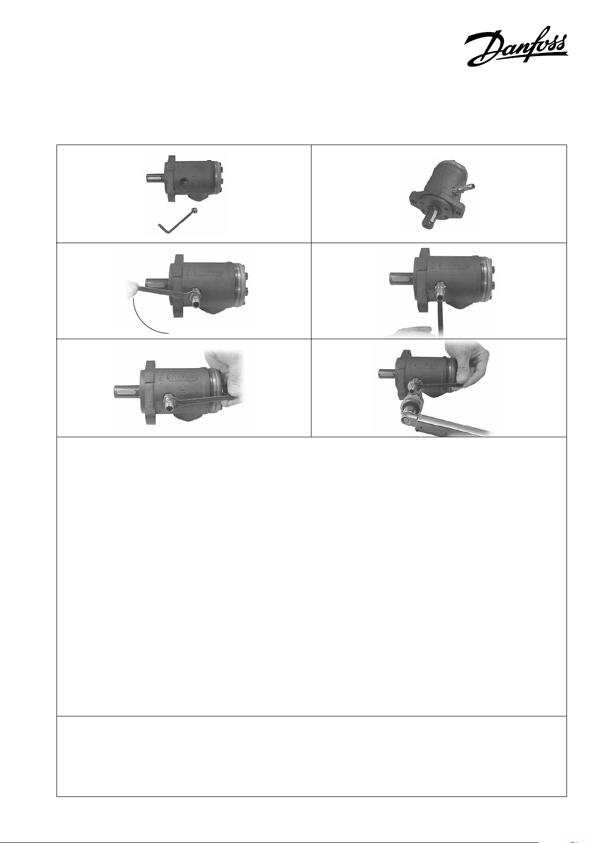
1. Fjern den monterede prop og skive på motoren (6 mm unbraco).
1. Remove the plug and washer from the motor (6 mm Allen
key).
1. Den Stopfen und Scheibe aus dem Motor entfernen (6 mm
Inbussschlüssel).
1. Ôter le bouchon et la rondelle du moteur (clé Allen à 6
cannelures).
2. Skru sensoren i, uden anvendelse af værktøj, til kontakt med
motorens aksel / møtrik.
2. Without tools screw in the sensor till it makes contact with
the shaft/nut of the motor.
2. Den Drehzahlgeber ohne Anwendung von Werkzeug
einschrauben, bis Kontakt mit Welle/Mutter des Motors
erreicht wird.
2. Visser le capteur sans utiliser de l’outil jusqu’à ce qu’il y ait
contact avec l’axe/l’écrou du moteur.
3. Skru sensoren 1/4 omgang (90°) ud igen som vist på foto 3a.
3. Turn 1/4 revolution back again (90°) as shown on photo 3a.
3. Den Drehzahlgeber wieder 1/4 Umdrehung (90°)
ausschrauben. Siehe Photo 3a.
3. Dévisser le capteur d’un quart de tour (90°) comme indiqué
sur la photo 3a
90°
4. Skru yderligere ud indtil de 2 gaffelflader (10 mm) er
4. Turn further back until the 10 mm flats of the sensor are
4. Weiter so ausschrauben, bis die zwei Gabelflächen am
4. Continuer à dévisser le capteur jusqu’à ce que les deux
5. Hold sensoren i denne position, medens omløber spændes
5. Keep the sensor in this position while tightening the
5. Den Drehzahlgeber in dieser Stellung halten während die
5. Maintenir le capteur dans cette position et serrer l’écrou en
oriente-ret i samme retning som motorens længdeakse.
Tolerance: ± 5°
aligned with th longitudinal axis of the motor. Tolerance ± 5°.
Sensor identisch mit der Längsachse vom Motor orientiert
sind. Toleranz ± 5°.
plats à fourche (10 mm) soient orientés dans la même
direction que l’axe longitudinal du moteur. Tolérance : ± 5°
med det foreskrevne tilspændingsmoment på 15 - 20 Nm.
compression nut to the prescribed torque of 15-20 Nm.
Überwurfmutter zum vorgeschriebenen Anzugsmoment
von 15-20 Nm angezogen wird.
appliquant le couple prescrit de 15 – 20 Nm.
For at sikre sensorens funktionsevne, er det nødvendigt at
trin 2 til 5 er udført korrekt og i den rigtige rækkefølge.
To make the sensor work, be sure to carry out the steps 2 – 5
correctly and in the right order of succession.
© Danfoss, 2021
-06 AN15288648257001-000203 • June 2021 1
Um die korrekte Funktion vom Drehzahlgeber zu sichern,
müssen die Anweisungen 2 bis 5 genau und in der richtigen
Reihenfolge beobachtet werden.
Le bon fonctionnement du capteur est garanti par l’exécution
correcte, et dans le bon ordre, des phases de montage 2 à 5.
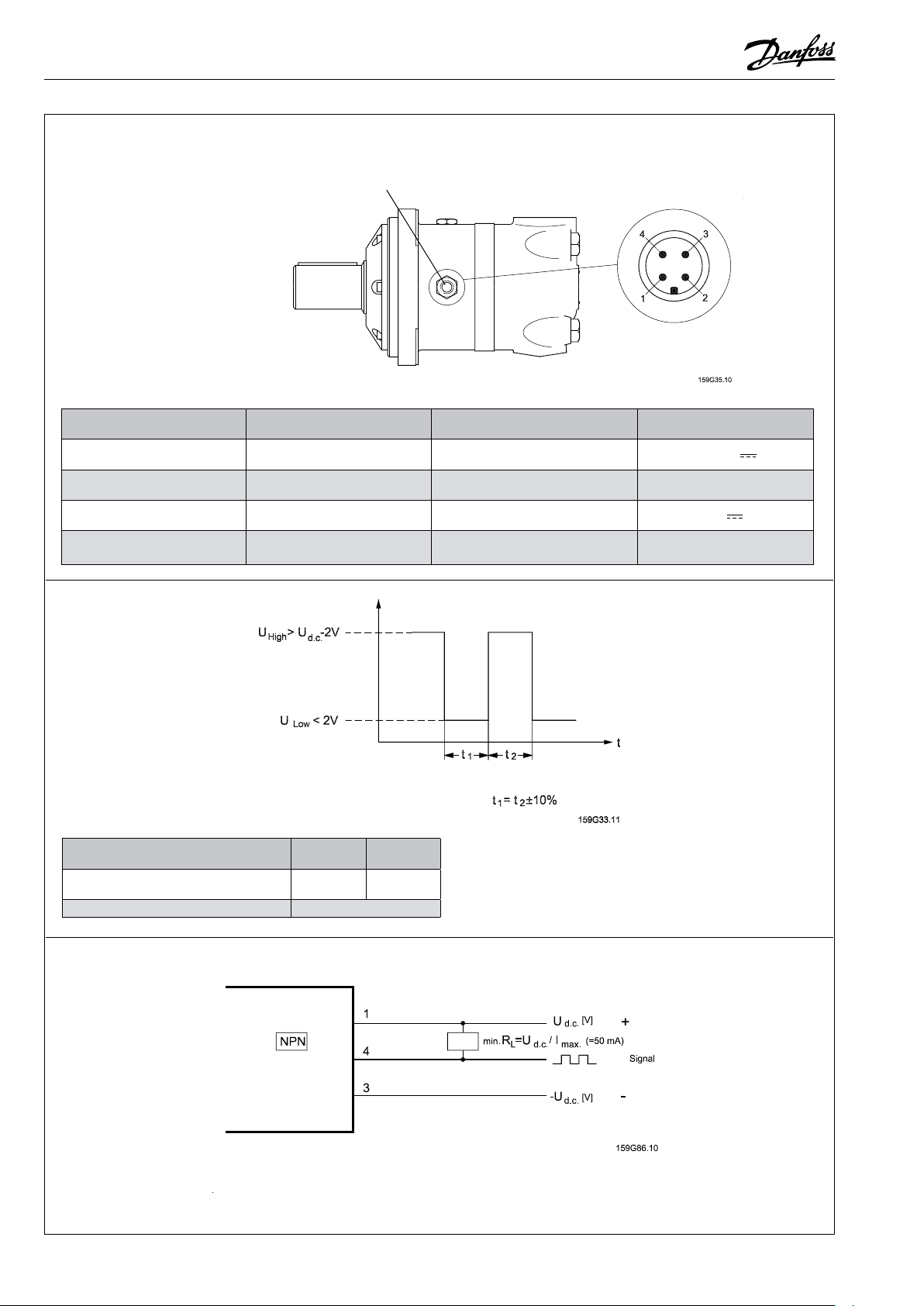
Tilslutning
Connection
Anschluß
Raccordement
Advarsel: Drej ikke soklen
Attention: Don’t turn the socket
Achtung: Den Sockel nicht drehen
Attention: Ne pas tourner le socle
Stik: Binder serie 713
Connection: Binder series 713
Stecker: Binder Serie 713
Connecteur: Binder sérié 713
Kabel
Cable
Kabel
Câbles
Stikben / Pin
Stiftstecker / Point de fiche
1 Brun / Brown / Braun / Brun
2 Hvid / White / Weiß / Blanc
3 Blå / Blue / Blau / Bleu
4 Sort / Black / Schwarz / Noir Signal
Ledningsfarve / Conductor
Leiterfarbe / Codes couleurs
Hastighedssignal
Speed signal
Drehzahlsignal
Signal de vitesse
Motortype / Motor type
Motor Typ / Type de moteur
Pulser pr. omdr./ Pulses per rev.
Pulsen per Umdr. / Impulsions Par tour
Belastning / Load / Belastung / Charge I
OMT EM OMV EM
84 102
= 50 mA
max
Betegnelse / Designation
Bezeichnung / Désignation
Ud.c. Forsyning / supply
Versorgung / Alimentation
Forbindes ikke / Not connected
Keine Verbindung / Non connecté
Ud.c. Forsyning / supply
Versorgung / Alimentation
Specifikation / Specification
Spezifikation / Spécification
11 - 30 V
0 V
Se nedenfor / See below
Siehe unten / Voir ci-dessous
Forbindelsesdiagram
Connection diagram
Anschlußschema
Raccordement électrique
2
AN15288648257001-000203 • June 2021
© Danfoss, 2021
-06
 Loading...