

Page 1
Electrical Installation
M1, M2, K1, K2 Electric Proportional
Controls
for H1B Bent Axis Motors
www.danfoss.com
Page 2

Electrical Installation
M1, M2, K1, K2 Electric Proportional Controls for H1B Motors
Revision history Table of revisions
Date Changed Rev
September 2018 Major update. 0301
September 2015 Converted to Danfosss layout. 0201
June 2009 First edition. 0101
2 | © Danfoss | September 2018 BC00000279en-000301
Page 3

Electrical Installation
M1, M2, K1, K2 Electric Proportional Controls for H1B Motors
Contents
Product overview
Electric proportional controls...................................................................................................................................................... 4
Electric proportional with PCOR................................................................................................................................................. 4
Electric BPD.........................................................................................................................................................................................4
Nomenclature....................................................................................................................................................................................5
M1CA and M2CA options.............................................................................................................................................................. 6
K1KA and K2KA options with PCOR...........................................................................................................................................8
K1K1 and K2K2 options with PCOR and electric BPD........................................................................................................10
Latest version of technical literature.......................................................................................................................................11
Electrical installation
2-pin DEUTSCH connector pinout........................................................................................................................................... 12
Pin compatibility............................................................................................................................................................................ 12
Mating connector parts list ....................................................................................................................................................... 12
©
Danfoss | September 2018 BC00000279en-000301 | 3
Page 4

Electrical Installation
M1, M2, K1, K2 Electric Proportional Controls for H1B Motors
Product overview
Electric proportional controls
The electric proportional control consists of a proportional solenoid which acts directly on a two-position,
three-way porting spool. When activated, the solenoid pushes on the spool which then ports high
pressure to the larger diameter of the servo piston. The servo piston and rotating group move to change
the displacement to the point where the pressures on the servo are in balance with the force from the
feedback spring.
De-energized = maximum displacement
With a de-energized to maximum displacement control, the de-energized proportional valve keeps the
motor at maximum displacement. When energized, the solenoid pushes on the porting spool which
moves to port high system pressure to the larger diameter end of the servo piston. Depending on the
current supplied to the proportional valve, the motor will stroke between maximum displacement at zero
current and minimum displacement at maximum current.
De-energized = minimum displacement
With a de-energized to minimum displacement control, the de-energized proportional valve keeps the
motor at minimum displacement. When energized, the solenoid pushes on the porting spool which
moves to port high system pressure to the larger diameter end of the servo piston. Depending on the
current supplied to the proportional valve, the motor will stroke between minimum displacement at zero
current and maximum displacement at maximum current.
Electric proportional with PCOR
In the de-energized state, the electric proportional control keeps the motor at minimum displacement
until system pressure rises above the PCOR setting. When the PCOR activates, it ports high system
pressure to the larger end of the servo piston, increasing the motor displacement to maximum.
Electric BPD
For propel applications, use the electric BPD option in conjunction with the PCOR option. The BPD shuttle
valve is located ahead of the pressure compensator control valve.
The BPD consists of an electric off/on solenoid and a two-position, three-way porting spool. The applied
logic allows the pressure compensator control to operate normally with high loop system pressure
during acceleration and cuts off the supply pressure during deceleration if the motor is running in a
pump mode (includes deceleration or overrun). This prevents rapid or uncontrolled deceleration while
the machine is slowing down. With the BPD solenoid de-energized, the porting spool is centered by
spring force.
The BPD solenoid must be controlled by a direction lever switch or an output signal from a microcontroller.
4 | © Danfoss | September 2018 BC00000279en-000301
Page 5
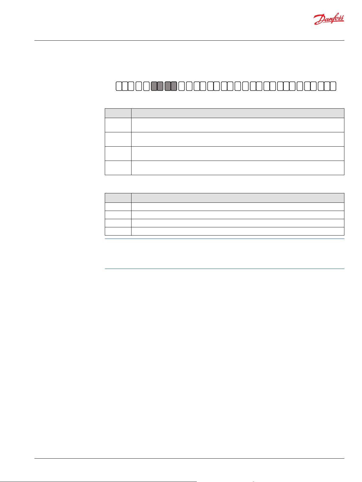
A B C D E F G H J K L M N P
H1 B
A
Q R
Z
A
N N N
Electrical Installation
M1, M2, K1, K2 Electric Proportional Controls for H1B Motors
Product overview
Nomenclature
B – Control options
Code Description
M1 Electric proportional control without electric PCOR, 12 V, de-energized = minimum displacement,
M2 Electric proportional control without electric PCOR, 24 V, de-energized = minimum displacement,
K1 Electric proportional control with electric PCOR, 12 V, de-energized = minimum displacement,
K2 Electric proportional control with electric PCOR, 24 V, de-energized = minimum displacement,
C – Servo supply options
Code Description
CA Without brake pressure defeat (BPD)
KA Without brake pressure defeat (BPD)
K1 With BPD 12 V, de-energized BPD = PCOR active at port A, DEUTSCH DT 04-2P connector
K2 With BPD 24 V, de-energized BPD = PCOR active at port A, DEUTSCH DT 04-2P connector
DEUTSCH DT 04-2P connector
DEUTSCH DT 04-2P connector
DEUTSCH DT 04-2P connector
DEUTSCH DT 04-2P connector
Only certain control options for the H1B motor use this electric proportional control. Please refer to the
motor’s nomenclature to determine if the motor is equipped with the proper option. You can find the
nomenclature on the motor’s nametag. For nomenclature details, refer to H1B Bent Axis Variable
Displacement Motors Technical Information, BC00000043.
©
Danfoss | September 2018 BC00000279en-000301 | 5
Page 6

A
B
n
max
min
C1
M5M4 MB
MA
L1
L2
N
P003428
M1M2
32°
6°
P003 484
0 200 400 600 800 1000 1200 1400 1600 1800
mA
0%
20%
40%
60%
80%
100%
Electrical Installation
M1, M2, K1, K2 Electric Proportional Controls for H1B Motors
Product overview
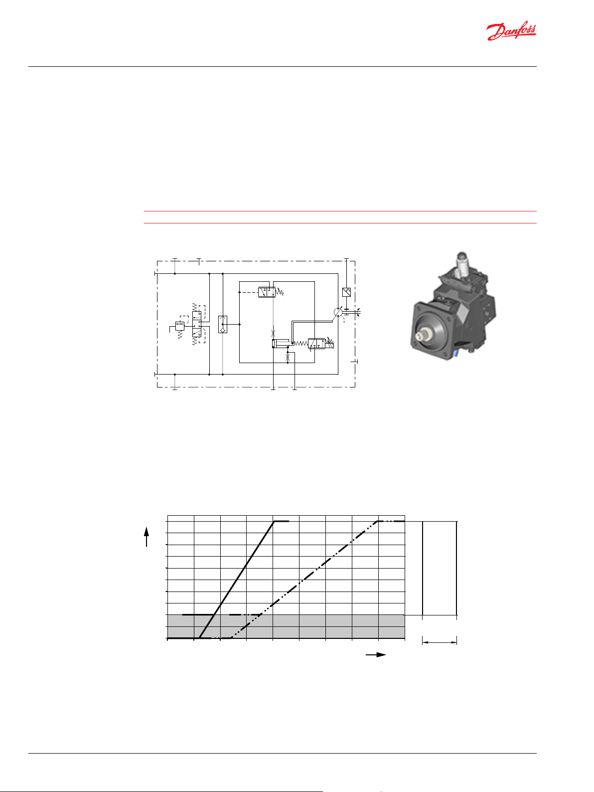
M1CA and M2CA options
M1 – electric proportional 12 V / de-energized = minimum displacement
CA – without Pressure Compensator Over Ride / without Brake Pressure Defeat
M2 – electric proportional 24 V / de-energized = minimum displacement
CA – without Pressure Compensator Over Ride / without Brake Pressure Defeat
Hydraulic schematic
A, B Main pressure lines
L1, L2 Drain lines
M4, M5 Gauge port servo pressure
MA, MB Gauge port system pressure
N Speed sensor (optional)
Displacement (%) versus Input Command (mA)
Options: M1CA, M2CA
Solenoid C1
De-energized = min. displacement
Full-energized = max. displacement
M1, M2 = M1, M2 Control
Grey area = Intended to be used for zero degree capability.
Formulas how to calculate start and end input command (mA) dependent on displacements
Input command (mA) % displ. Control *1 Control *2
Start input command from 0 % 480 ± 10 240 ± 5
6 | © Danfoss | September 2018 BC00000279en-000301
from x % min. (Vgx/V
) x 1110 + 480 (Vgx/V
gmax
) x 570 + 240
gmax
Page 7

W
Electrical Installation
M1, M2, K1, K2 Electric Proportional Controls for H1B Motors
Product overview
Formulas how to calculate start and end input command (mA) dependent on displacements (continued)
Input command (mA) % displ. Control *1 Control *2
End input command at 100 % 1590 ± 130 810 ± 67
at y % max. (Vgy/V
Maximum allowed current 1800 920
Proportional solenoid data C1
Description 12 V 24 V
Maximum current 1800 mA 920 mA
Nominal coil resistance @ 20 °C [68 °F] 3.66 Ω 14.20 Ω
@ 80 °C [176 °F] 4.52 Ω 17.52 Ω
Inductance 33 mH 140 mH
PWM signal frequency Range 70 – 200 Hz
Recommended
IP Rating IEC 60 529 IP 67
DIN 40 050, part 9 IP 69K with mating connector
Connector color Black
*
PWM signal required for optimum control performance.
*
) x 1110 + 480 (Vgy/V
gmax
150 Hz
) x 570 + 240
gmax
Warning
Zero degree capability results in a high risk of overspeed and drops in efficiency if the motor operates
between 0–20% displacement.
©
Danfoss | September 2018 BC00000279en-000301 | 7
Page 8
W
B
A
n
N
M4
M5
L2
L1
min max
C1
MA
MB
P301 463
32°
6°
160 bar
[2321 psi]
300 bar
[4351 psi]
PCOR
0 200 400 600 800 1000 1200 1400 1600 1800
P003 486
K1
K2
mA
0%
20%
40%
60%
80%
100%
Z
Electrical Installation
M1, M2, K1, K2 Electric Proportional Controls for H1B Motors
Product overview
K1KA and K2KA options with PCOR
K1 – electric proportional 12 V / de-energized = min. displacement / with PCOR
KA – with Pressure Compensator Over Ride / without Brake Pressure Defeat
K2 – electric proportional 24 V / de-energized = min. displacement / with PCOR
KA – with Pressure Compensator Over Ride / without Brake Pressure Defeat
Warning
This control is not for use in propel applications.
Hydraulic schematic
A, B Main pressure lines
L1, L2 Drain lines
M4, M5 Gauge port servo pressure
MA, MB Gauge port system pressure
N Speed sensor (optional)
Displacement (%) versus Input Command (mA)
Options K1KA, K2KA
Solenoid C1
De-energized = min. displacement
Full-energized = max. displacement
K1, K2 = K1, K2 Control
Z = Start setting range
Grey area = Intended to be used for zero degree capability.
8 | © Danfoss | September 2018 BC00000279en-000301
Page 9

W
Electrical Installation
M1, M2, K1, K2 Electric Proportional Controls for H1B Motors
Product overview
Formulas how to calculate start and end input command (mA) dependent on displacements
Input command (mA) % displ. Control *1 Control *2
Start input command from 0 % 480 ± 10 240 ± 5
from x % min. (Vgx/V
End input command at 100 % 1590 ± 130 810 ± 67
at y % max. (Vgy/V
Maximum allowed current 1800 920
Where:
) x 1110 + 480 (Vgx/V
gmax
) x 1110 + 480 (Vgy/V
gmax
) x 570 + 240
gmax
) x 570 + 240
gmax
V
V
V
Maximum, theoretic possible motor displacement per revolution (cm3/rev)
gmax
Minimum displacement setting of desired unit (cm3/rev)
gx
Maximum displacement setting of desired unit (cm3/rev)
gy
x Minimum displacement (%)
y Maximum displacement (%)
Proportional solenoid data C1
Description 12 V 24 V
Maximum current 1800 mA 920 mA
Nominal coil resistance @ 20 °C [68 °F] 3.66 Ω 14.20 Ω
@ 80 °C [176 °F] 4.52 Ω 17.52 Ω
Inductance 33 mH 140 mH
PWM signal frequency Range 70 – 200 Hz
Recommended
IP Rating IEC 60 529 IP 67
DIN 40 050, part 9 IP 69K with mating connector
Connector color Black
*
PWM signal required for optimum control performance.
*
150 Hz
Warning
Zero degree capability results in a high risk of overspeed and drops in efficiency if the motor operates
between 0–20% displacement.
©
Danfoss | September 2018 BC00000279en-000301 | 9
Page 10

A
B
n
min max
C5
C1
M4 MB
M5
P003433
L1
L2
NMA
32°
6°
160 bar
[2321 psi]
300 bar
[4351 psi]
PCOR
0 200 400 600 800 1000 1200 1400 1600 1800
P003 486
K1
K2
mA
0%
20%
40%
60%
80%
100%
Z
Electrical Installation
M1, M2, K1, K2 Electric Proportional Controls for H1B Motors
Product overview
K1K1 and K2K2 options with PCOR and electric BPD
K1 – electric proportional 12 V / de-energized = min. displacement / with PCOR
K1 – with PCOR / with electric BPD 12 V / de-energized BPD = PCOR active at port A
K2 – electric proportional 24 V / de-energized = min. displacement / with PCOR
K2 – with PCOR / with electric BPD 24 V / de-energized BPD = PCOR active at port A
Hydraulic schematic
A, B Main pressure lines
L1, L2 Drain lines
M4, M5 Gauge port servo pressure
MA, MB Gauge port system pressure
N Speed sensor (optional)
Displacement (%) versus Input Command (mA)
Options K1K1, K2K2
Solenoid C1
De-energized = min. displacement
Full-energized = max. displacement
10 | © Danfoss | September 2018 BC00000279en-000301
K1, K2 = K1, K2 Control
Z = Start setting range
Grey area = Intended to be used for zero degree capability.
For the formulas to calculate start and end input command dependent on displacements please see K1KA
and K2KA options with PCOR on page 8.
Page 11

W
Electrical Installation
M1, M2, K1, K2 Electric Proportional Controls for H1B Motors
Product overview
Proportional control solenoid data C1
Description 12 V 24 V
Maximum current 1800 mA 920 mA
Nominal coil resistance @ 20 °C [68 °F] 3.66 Ω 14.20 Ω
@ 80 °C [176 °F] 4.52 Ω 17.52 Ω
Inductance 33 mH 140 mH
PWM signal frequency Range 70 – 200 Hz
Recommended
IP Rating IEC 60 529 IP 67
DIN 40 050, part 9 IP 69K with mating connector
Connector color Black
*
PWM signal required for optimum control performance.
Two-position solenoid data C5 (Brake pressure defeat)
Description 12 V 24 V
Supply voltage Minimum 9.5 V
Max. (continuous) 14.6 V
Nominal coil resistance @ 20 °C [68 °F] 8.4 Ω 34.5 Ω
Input current Recommended 1050 mA 500 mA
IP Rating IEC 60 529 IP 67
DIN 40 050, part 9 IP 69K with mating connector
Bi-directional diode yes
Connector color Black
*
150 Hz
DC
DC
19 V
29 V
DC
DC
Warning
Zero degree capability results in a high risk of overspeed and drops in efficiency if the motor operates
between 0–20% displacement.
Latest version of technical literature
Danfoss product literature is online at: https://www.danfoss.com/en/search/
©
Danfoss | September 2018 BC00000279en-000301 | 11
Page 12

1 2
Electrical Installation
M1, M2, K1, K2 Electric Proportional Controls for H1B Motors
Electrical installation
2-pin DEUTSCH connector pinout
1. PWM signal
2. Ground
Alternative pinout:
1. Ground
2. PWM signal
Pin compatibility
PLUS+1® module pin type
Pin Function
1, 2 PWMOUT/DOUT/PVG Power supply
1, 2 PWMOUT/DOUT/PVGOUT
1, 2 Power ground
*
Use output pins with configurable PWM frequency.
*
*
Mating connector parts list
Connector ordering data
Description Quantity Ordering number
Mating connector 1 DEUTSCH DT06-2S
Wedge lock 1 DEUTSCH W2S
Socket contact (16 and 18 AWG) 2 DEUTSCH 0462-201-16141
Danfoss mating connector kit 1 K29657
12 | © Danfoss | September 2018 BC00000279en-000301
Page 13

Electrical Installation
M1, M2, K1, K2 Electric Proportional Controls for H1B Motors
©
Danfoss | September 2018 BC00000279en-000301 | 13
Page 14

Electrical Installation
M1, M2, K1, K2 Electric Proportional Controls for H1B Motors
14 | © Danfoss | September 2018 BC00000279en-000301
Page 15

Electrical Installation
M1, M2, K1, K2 Electric Proportional Controls for H1B Motors
©
Danfoss | September 2018 BC00000279en-000301 | 15
Page 16

Danfoss
Power Solutions GmbH & Co. OHG
Krokamp 35
D-24539 Neumünster, Germany
Phone: +49 4321 871 0
Danfoss
Power Solutions ApS
Nordborgvej 81
DK-6430 Nordborg, Denmark
Phone: +45 7488 2222
Danfoss
Power Solutions (US) Company
2800 East 13th Street
Ames, IA 50010, USA
Phone: +1 515 239 6000
Danfoss
Power Solutions Trading
(Shanghai) Co., Ltd.
Building #22, No. 1000 Jin Hai Rd
Jin Qiao, Pudong New District
Shanghai, China 201206
Phone: +86 21 3418 5200
Products we offer:
Comatrol
www.comatrol.com
Turolla
www.turollaocg.com
Hydro-Gear
www.hydro-gear.com
Daikin-Sauer-Danfoss
www.daikin-sauer-danfoss.com
DCV directional control
•
valves
Electric converters
•
Electric machines
•
Electric motors
•
Hydrostatic motors
•
Hydrostatic pumps
•
Orbital motors
•
PLUS+1® controllers
•
PLUS+1® displays
•
PLUS+1® joysticks and
•
pedals
PLUS+1® operator
•
interfaces
PLUS+1® sensors
•
PLUS+1® software
•
PLUS+1® software services,
•
support and training
Position controls and
•
sensors
PVG proportional valves
•
Steering components and
•
systems
Telematics
•
Danfoss Power Solutions is a global manufacturer and supplier of high-quality hydraulic and
electric components. We specialize in providing state-of-the-art technology and solutions
that excel in the harsh operating conditions of the mobile off-highway market as well as the
marine sector. Building on our extensive applications expertise, we work closely with you to
ensure exceptional performance for a broad range of applications. We help you and other
customers around the world speed up system development, reduce costs and bring vehicles
and vessels to market faster.
Danfoss Power Solutions – your strongest partner in mobile hydraulics and mobile
electrification.
Go to www.danfoss.com for further product information.
We offer you expert worldwide support for ensuring the best possible solutions for
outstanding performance. And with an extensive network of Global Service Partners, we also
provide you with comprehensive global service for all of our components.
Local address:
Danfoss can accept no responsibility for possible errors in catalogues, brochures and other printed material. Danfoss reserves the right to alter its products without notice. This also applies to products
already on order provided that such alterations can be made without subsequent changes being necessary in specifications already agreed.
All trademarks in this material are property of the respective companies. Danfoss and the Danfoss logotype are trademarks of Danfoss A/S. All rights reserved.
©
Danfoss | September 2018 BC00000279en-000301
 Loading...