

Danfoss OMT, OMV User guide
Technical Information
Orbital Motors
OMT and OMV
www.danfoss.com

Technical Information
OMT and OMV Orbital Motors
Revision history |
Table of revisions |
|
|
|
|
|
|
|
Date |
Changed |
Rev |
|
|
|
|
|
September 2021 |
Updated catalogue to reflect current offerings |
0801 |
|
|
|
|
|
|
Changed document number from 'BC00000090' and '520L0407' to 'BC152886483862' |
0702 |
|
|
|
|
|
March 2016 |
Engineering Tomorrow |
0602 |
|
|
|
|
|
February 2016 |
Corrected Hardening specification for OMTS, OMVS |
0601 |
|
|
|
|
|
November 2014 |
Converted to Danfoss layout - DITA CMS |
FA |
|
|
|
|
|
December 2013 |
Table updated |
EL |
|
|
|
|
|
June 2013 |
Drawing corrected |
EK |
|
|
|
|
|
April 2013 |
Drawing corrected |
EJ |
|
|
|
|
|
January 2013 |
Correct drawing |
EI |
|
|
|
|
|
November 2012 |
Planetary Gears deleted |
EH |
|
|
|
|
|
July 2012 |
Typo in ‘Major dia’ |
EG |
|
|
|
|
|
November 2010 |
Dimensions changed |
EF |
|
|
|
|
|
November 2009 |
conversions, and layout adjusted |
ED |
|
|
|
|
2 | © Danfoss | September 2021 |
BC152886483862en-000801 |

Technical Information |
|
OMT and OMV Orbital Motors |
|
Contents |
|
Orbital motors |
|
Orbital Motors Introduction......................................................................................................................................................... |
5 |
Orbital Motors Features............................................................................................................................................................ |
5 |
Technical Features...................................................................................................................................................................... |
5 |
Orbital Motors Application Areas.......................................................................................................................................... |
5 |
Orbital Motors Literature Overview........................................................................................................................................... |
6 |
Speed, torque, and output............................................................................................................................................................ |
7 |
OMT |
|
Versions................................................................................................................................................................................................ |
8 |
Features.......................................................................................................................................................................................... |
8 |
Code numbers................................................................................................................................................................................... |
8 |
Ordering......................................................................................................................................................................................... |
9 |
Technical data.................................................................................................................................................................................... |
9 |
Maximum permissible shaft seal pressure......................................................................................................................... |
9 |
Motor with check valves and without use of drain connection........................................................................... |
9 |
Motor with check valves and with drain connection............................................................................................... |
9 |
Motor with check valves and with drain connection............................................................................................. |
10 |
OMT, OMTW, OMTS, OMT FX OMT FL and OMT FH...................................................................................................... |
10 |
Pressure drop in motor........................................................................................................................................................... |
12 |
Oil flow in drain line................................................................................................................................................................. |
12 |
Direction of shaft rotation..................................................................................................................................................... |
13 |
Permissible shaft loads for OMT.......................................................................................................................................... |
13 |
OMT Function diagrams.............................................................................................................................................................. |
14 |
Function diagram use............................................................................................................................................................. |
17 |
Shaft version.................................................................................................................................................................................... |
18 |
Port thread versions................................................................................................................................................................. |
21 |
Dimensions....................................................................................................................................................................................... |
22 |
OMT standard flange - European version........................................................................................................................ |
22 |
OMT standard flange - US version...................................................................................................................................... |
24 |
OMT Wheel - European version........................................................................................................................................... |
26 |
OMT Wheel - US version......................................................................................................................................................... |
28 |
OMT Brake-wheel - European version............................................................................................................................... |
30 |
OMT Brake-standard - European version......................................................................................................................... |
32 |
OMT short - European version............................................................................................................................................. |
33 |
OMTS.................................................................................................................................................................................................. |
34 |
Installation................................................................................................................................................................................... |
34 |
Attached component dimensions...................................................................................................................................... |
35 |
Attached component internal splines.............................................................................................................................. |
35 |
Motor or attached component drain connection......................................................................................................... |
36 |
OMT versions and code numbers |
|
OMV versions and code numbers |
|
OMV versions and code numbers............................................................................................................................................ |
38 |
OMV technical data |
|
OMV, OMVW, OMVS technical data......................................................................................................................................... |
40 |
Maximum permissible shaft seal pressure............................................................................................................................ |
40 |
Motor with check valves and without use of drain connection.............................................................................. |
40 |
Motor with check valves and with drain connection.................................................................................................. |
41 |
Pressure drop in motor................................................................................................................................................................ |
41 |
Oil flow in drain line...................................................................................................................................................................... |
41 |
Direction of shaft rotation........................................................................................................................................................... |
42 |
Permissible shaft loads................................................................................................................................................................. |
42 |
OMV mounting flange: Standard........................................................................................................................................ |
42 |
OMV mounting flange: Wheel............................................................................................................................................. |
43 |
OMV mounting flange: SAE-C.............................................................................................................................................. |
43 |
OMV function diagrams |
|
OMV 315 function diagram........................................................................................................................................................ |
45 |
© Danfoss | September 2021 |
BC152886483862en-000801 | 3 |

Technical Information |
|
OMT and OMV Orbital Motors |
|
Contents |
|
OMV 400 function diagram........................................................................................................................................................ |
45 |
OMV 500 function diagram........................................................................................................................................................ |
46 |
OMV 630 function diagram........................................................................................................................................................ |
46 |
OMV 800 function diagram........................................................................................................................................................ |
47 |
Shaft version |
|
OMV shaft version.......................................................................................................................................................................... |
48 |
OMV port thread versions........................................................................................................................................................... |
52 |
OMV dimensions |
|
OMV dimensions - European version..................................................................................................................................... |
53 |
OMV standard flange - European version........................................................................................................................ |
53 |
OMV Wheel - European version........................................................................................................................................... |
55 |
OMV short - European version............................................................................................................................................. |
56 |
OMV dimensions - US version................................................................................................................................................... |
57 |
OMV standard flange - US version...................................................................................................................................... |
58 |
OMV SAE-C flange - US version............................................................................................................................................ |
60 |
OMV wheel - US version......................................................................................................................................................... |
62 |
OMVS |
|
Installing the OMVS....................................................................................................................................................................... |
64 |
Attached component dimensions for OMVS....................................................................................................................... |
64 |
Attached component internal splines for OMVS................................................................................................................ |
65 |
Motor or attached component drain connection.............................................................................................................. |
65 |
4 | © Danfoss | September 2021 |
BC152886483862en-000801 |

Technical Information
OMT and OMV Orbital Motors
Orbital motors
Orbital Motors Introduction
Danfoss is a world leader within production of low speed orbital motors with high torque. We can offer more than 1500 different orbital motors, categorized in types, variants and sizes (including different shaft versions).
The motors size vary (rated displacement) from 130 to 800 cm3 [7.9 to 48.9 in3] per revolution.
•Motor sizes:
‒OMT and OMV
‒TMK
‒TMT
‒TMTHW
‒TMVW
Speeds range up to approximate 600 min-1 (rpm).
Maximum operating torques up to 3400 N•m [30090 lb•in] (peak) and maximum outputs up to 70 kW [95 hp].
Orbital Motors Features
•Smooth running over the entire speed range
•Constant operating torque over a wide speed range
•High starting torque
•High return pressure without the use of drain line (high pressure shaft seal)
•High efficiency
•High radial and axial bearing capacity
•Long life under extreme operating conditions
•Robust and compact design
•For applications in both open and closed loop hydraulic systems
•Suitable for a wide variety of hydraulics fluids
Technical Features
The program is characterized by technical features appealing to a large number of applications and by motors that can be adapted to a given application.
Adaptions comprise the following variants:
•Motors with:
‒integrated negative holding brake
‒speed sensor
‒black finish paint
•Short motors without bearings or Ultra short motors
•Wheel motors with recessed mounting flange
Orbital Motors Application Areas
The orbital motors are used in the following application areas:
•Construction equipment
•Agricultural equipment
•Material handling & Lifting equipment
© Danfoss | September 2021 |
BC152886483862en-000801 | 5 |

Technical Information
OMT and OMV Orbital Motors
Orbital motors
•Forestry equipment
•Lawn and turf equipment
•Machine tools and stationary equipment
•Marine equipment
•Special purpose
Orbital Motors Literature Overview
A general catalog of all Orbital Motors with technical data gives a quick motor reference based on: selection of orbital motor, function in hydraulic systems, power, torque, speed and capabilities. More detailed information can be found in an individual motor catalogs.
Literature title |
Literature type |
Reference number |
|
|
|
Orbital Motors in General |
Technical Information |
BC152886483554 |
|
|
|
OMT and OMV Orbital Motors |
Technical Information |
BC152886483862 |
|
|
|
TMK, TMKW, TMK FL Orbital Motors |
Technical Information |
BC152886483785 |
|
|
|
TMT, TMTU, TMTW, TMT FL Orbital Motors |
Technical Information |
BC152886483631 |
|
|
|
TMTHW Orbital Motors |
Technical Information |
BC152986483537 |
|
|
|
6 | © Danfoss | September 2021 |
BC152886483862en-000801 |
Technical Information
OMT and OMV Orbital Motors
Orbital motors
Speed, torque, and output
Maximum speed |
|
|
|
|
min-1 |
|
|
|
|
(rpm) |
|
|
|
|
800 |
|
|
|
|
600 |
|
|
|
|
400 |
|
|
|
|
200 |
|
|
|
|
160 200 |
250 315 400 500 |
315 400 500 |
630 |
800 |
|
OMT |
OMV |
|
|
Maximum torque
lbf• in N• m |
|
|
|
|
|
|
|
22000 |
2400 |
|
|
|
|
|
|
20000 |
2200 |
|
|
|
|
|
|
18000 |
2000 |
|
|
|
|
|
|
16000 |
1800 |
|
|
|
|
|
|
14000 |
1600 |
|
|
|
|
|
|
12000 |
1400 |
|
|
|
|
|
|
10000 |
1200 |
|
|
|
|
|
|
8000 |
1000 |
|
|
|
|
|
|
800 |
|
|
|
|
|
|
|
|
|
|
|
|
|
|
|
6000 |
600 |
|
|
|
|
|
|
|
|
|
|
|
|
|
|
4000 |
400 |
|
|
|
|
|
|
|
|
|
|
|
|
|
|
2000 |
200 |
|
|
|
|
|
|
|
160 200 |
250 |
315 400 500 |
315 400 |
500 |
630 |
800 |
Maximum output |
|
|
|
|
|
|
|
hp |
kW |
|
|
|
|
|
80 |
60 |
|
|
|
|
|
60 |
50 |
|
|
|
|
|
40 |
|
|
|
|
|
|
|
|
|
|
|
|
|
40 |
30 |
|
|
|
|
|
20 |
20 |
|
|
|
|
|
10 |
|
|
|
|
|
|
|
|
|
|
|
|
|
|
160 200 250 315 |
400 500 |
315 400 |
500 |
630 |
800 |
|
OMT |
|
|
OMV |
|
|
|
1 |
|
2 |
|
|
|
1.Intermittend values
2.Continuous values
The bar diagrams above are useful for a quick selection of relevant motor size for the application. The final motor size can be determined by using the function diagram for each motor size: see OMT Function diagrams on page 14, or OMV function diagrams on page 45.
The function diagrams are based on actual tests on a representative number of motors from our production. The diagrams apply to a return pressure between 5 and 10 bar [75 and 150 psi] when using mineral based hydraulic oil with a viscosity of 35 mm2/s [165 SUS] and a temperature of 50°C [120°F].
© Danfoss | September 2021 |
BC152886483862en-000801 | 7 |

Technical Information
OMT and OMV Orbital Motors
OMT
Versions
OMT versions
Mounting |
Shaft |
Port size |
Europea |
US |
Drain |
Check valve |
Low |
High |
Main type |
flange |
|
|
n version |
version |
connection |
|
pressure |
pressure |
designation |
|
|
|
|
|
|
|
release |
release |
|
|
|
|
|
|
|
|
|
|
|
Standard |
Cyl. 40 mm |
G 3/4 |
X |
|
Yes |
Yes |
|
|
OMT |
flange |
|
|
|
|
|
|
|
|
|
Cyl. 1.5 in |
1 1/16-12 UN |
|
X |
Yes |
Yes |
|
|
OMT |
|
|
|
|
|
||||||
|
|
|
|
|
|
|
|
|
|
|
Splined 1.5 in |
G 3/4 |
X |
|
Yes |
Yes |
|
|
OMT |
|
|
|
|
|
|
|
|
|
|
|
|
1 1/16-12 UN |
|
X |
Yes |
Yes |
|
|
OMT |
|
|
|
|
|
|
|
|
|
|
|
Tapered 45 mm |
G 3/4 |
X |
|
Yes |
Yes |
|
|
OMT |
|
|
|
|
|
|
|
|
|
|
|
Tapered 1.75 in |
1 1/16-12 UN |
|
X |
Yes |
Yes |
|
|
OMT |
|
|
|
|
|
|
|
|
|
|
|
P.t.o. |
G 3/4 |
X |
|
Yes |
Yes |
|
|
OMT |
|
|
|
|
|
|
|
|
|
|
Wheel |
Cyl. 40 mm |
G 3/4 |
X |
|
Yes |
Yes |
|
|
OMTW |
|
|
|
|
|
|
|
|
|
|
|
Tapered 45 mm |
G 3/4 |
X |
|
Yes |
Yes |
|
|
OMTW |
|
|
|
|
|
|
|
|
|
|
|
Tapered 1.75 in |
1 1/16-12 UN |
|
X |
Yes |
Yes |
|
|
OMTW |
|
|
|
|
|
|
|
|
|
|
Brake-wheel |
Wheel bolt flange |
G 3/4 |
X |
|
Yes |
No |
X |
|
OMT FX |
|
|
|
|
|
|
|
|
|
|
|
Thread hole flange |
G 3/4 |
X |
|
Yes |
No |
X |
|
OMT FX |
|
|
|
|
|
|
|
|
|
|
Brake- |
Cyl. 40 mm |
G 3/4 |
X |
|
Yes |
No |
X |
|
OMT FL |
standard |
|
|
|
|
|
|
|
|
|
Splined 1.5 in |
G 3/4 |
X |
|
Yes |
No |
X |
|
OMT FL |
|
|
|
|
|||||||
|
|
|
|
|
|
|
|
|
|
|
Cyl. 40 mm |
G 3/4 |
X |
|
Yes |
No |
|
X |
OMT FH |
|
|
|
|
|
|
|
|
|
|
|
Splined 1.5 in |
G 3/4 |
X |
|
Yes |
No |
|
X |
OMT FH |
|
|
|
|
|
|
|
|
|
|
Short |
No output shaft |
G 3/4 |
X |
|
Yes |
Yes |
|
|
OMTS |
|
|
|
|
|
|
|
|
|
|
Features
Features available (options):
•Speed sensor
•Motor with tacho connection
•Viton shaft seal
•Painted
•Ultra short
Code numbers
OMT code numbers
Code |
Displacement [cm3] |
|
|
|
|
||
Numbers |
|
|
|
|
|
|
|
160 |
200 |
250 |
315 |
400 |
500 |
||
|
|||||||
|
|
|
|
|
|
|
|
151B |
3000 |
3001 |
3002 |
3003 |
3004 |
3005 |
|
|
|
|
|
|
|
|
|
151B |
2050 |
2051 |
2052 |
2053 |
2054 |
2055 |
|
|
|
|
|
|
|
|
|
151B |
3006 |
3007 |
3008 |
3009 |
3010 |
3011 |
|
|
|
|
|
|
|
|
|
151B |
2056 |
2057 |
2058 |
2059 |
2060 |
2061 |
|
|
|
|
|
|
|
|
|
151B |
3012 |
3013 |
3014 |
3015 |
3016 |
3017 |
|
|
|
|
|
|
|
|
|
151B |
2062 |
2063 |
2064 |
2065 |
2066 |
2067 |
|
|
|
|
|
|
|
|
|
8 | © Danfoss | September 2021 |
BC152886483862en-000801 |

Technical Information
OMT and OMV Orbital Motors
OMT
OMT code numbers (continued)
Code |
Displacement [cm3] |
|
|
|
|
||
Numbers |
|
|
|
|
|
|
|
160 |
200 |
250 |
315 |
400 |
500 |
||
|
|||||||
|
|
|
|
|
|
|
|
151B |
3018 |
3019 |
3020 |
3021 |
3022 |
3023 |
|
|
|
|
|
|
|
|
|
151B |
3024 |
3025 |
3026 |
3027 |
3028 |
3029 |
|
|
|
|
|
|
|
|
|
151B |
3030 |
3031 |
3032 |
3033 |
3034 |
3035 |
|
|
|
|
|
|
|
|
|
151B |
2080 |
2081 |
2082 |
2083 |
2084 |
2085 |
|
|
|
|
|
|
|
|
|
151B |
3207 |
3208 |
3209 |
3210 |
3211 |
3212 |
|
|
|
|
|
|
|
|
|
151B |
3200 |
3201 |
3202 |
3203 |
3204 |
3205 |
|
|
|
|
|
|
|
|
|
151B |
4000 |
4001 |
4002 |
4003 |
4004 |
4005 |
|
|
|
|
|
|
|
|
|
151B |
4007 |
4008 |
4009 |
4010 |
4011 |
4012 |
|
|
|
|
|
|
|
|
|
151B |
4021 |
4022 |
4023 |
4024 |
4025 |
4026 |
|
|
|
|
|
|
|
|
|
151B |
4028 |
4029 |
4030 |
4031 |
4032 |
4033 |
|
|
|
|
|
|
|
|
|
151B |
3036 |
3037 |
3038 |
3039 |
3040 |
3041 |
|
|
|
|
|
|
|
|
|
Ordering
Add the four digit prefix “151B” to the four digit numbers from the chart for complete code number. Example:
151B3002 for an OMT 250 with standard flange, cyl. 40 mm shaft and port size G 3/4.
Orders will not be accepted without the four digit prefix.
Technical data
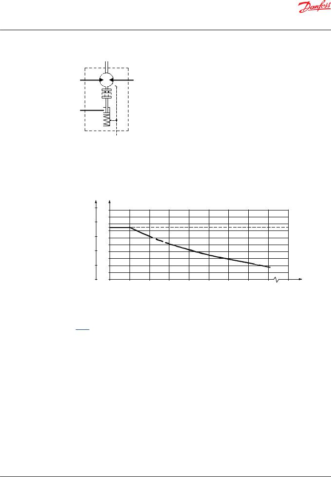
Maximum permissible shaft seal pressure
Motor with check valves and without use of drain connection
The pressure on the shaft seal never exceeds the pressure in the return line.
151-320.10
Motor with check valves and with drain connection
The shaft seal pressure equals the pressure on the drain line.
OMT FX, OMT FL and OMT FH must always be fitted with drain line.
Maximum pressure in drain line is 5 bar [75 psi]
© Danfoss | September 2021 |
BC152886483862en-000801 | 9 |
Technical Information
OMT and OMV Orbital Motors
OMT
151-1405.10
Motor with check valves and with drain connection
The shaft seal pressure equals the pressure on the drain line.
Maximum return pressure without drain line or maximum pressure in the drain line
P |
P |
|
|
|
|
|
|
|
|
|
|
psi |
bar |
|
|
|
|
|
|
|
|
|
|
1500 |
100 |
|
|
|
|
|
|
|
|
|
|
|
|
|
|
|
|
|
|
|
|
|
|
1200 |
90 |
|
|
|
|
|
|
|
|
|
|
80 |
|
|
|
|
|
|
|
|
|
|
|
|
|
|
|
|
|
|
|
|
|
|
|
|
70 |
|
|
|
|
|
|
|
|
|
|
900 |
60 |
|
|
|
|
|
|
|
|
|
|
|
|
|
|
|
|
|
|
|
|
|
|
|
50 |
|
|
|
|
|
|
|
|
|
|
600 |
40 |
|
|
|
|
|
|
|
|
|
|
|
|
|
|
|
|
|
|
|
|
|
|
|
30 |
|
|
|
|
|
|
|
|
|
|
300 |
20 |
|
|
|
|
|
|
|
|
|
|
|
|
|
|
|
|
|
|
|
|
|
|
|
10 |
|
|
|
|
|
|
|
|
|
|
0 |
0 |
|
|
|
|
|
|
|
|
|
min-1 |
|
0 |
100 |
200 |
300 |
400 |
500 |
600 |
700 |
800 |
max. |
|
|
(rpm) |
||||||||||
|
|
|
|
|
|
|
|
|
|
|
|
|
|
|
|
|
|
|
|
|
|
151-1674.10 |
|
– – – – Intermittent operation: the permissible values may occur for max. 10% of every minute.
Continuous operation
OMT, OMTW, OMTS, OMT FX OMT FL and OMT FH
Technical data for OMT, OMTW, OMTS, OMT FX OMT FL and OMT FH
Type |
|
|
OMT |
OMT |
OMT |
OMT |
OMT |
OMT |
|
|
|
OMTW |
OMTW |
OMTW |
OMTW |
OMTW |
OMTW |
|
|
|
OMTS |
OMTS |
OMTS |
OMTS |
OMTS |
OMTS |
|
|
|
OMT FX |
OMT FX |
OMT FX |
OMT FX |
OMT FX |
OMT FX |
|
|
|
OMT FL |
OMT FL |
OMT FL |
OMT FL |
OMT FL |
OMT FL |
|
|
|
OMT FH |
OMT FH |
OMT FH |
OMT FH |
OMT FH |
OMT FH |
|
|
|
|
|
|
|
|
|
Motor size |
|
|
160 |
200 |
250 |
315 |
400 |
500 |
|
|
|
|
|
|
|
|
|
Geometric displacement |
cm3 |
|
161.1 |
201.4 |
251.8 |
326.3 |
410.9 |
523.6 |
|
[in3] |
|
[9.83] |
[12.29] |
[15.37] |
[19.91] |
[25.07] |
[31.95] |
Maximum speed |
min-1 |
cont. |
625 |
625 |
500 |
380 |
305 |
240 |
|
[rpm] |
|
|
|
|
|
|
|
|
int1) |
780 |
750 |
600 |
460 |
365 |
285 |
|
|
|
10 | © Danfoss | September 2021 |
BC152886483862en-000801 |
Technical Information
OMT and OMV Orbital Motors
OMT
Technical data for OMT, OMTW, OMTS, OMT FX OMT FL and OMT FH (continued)
Type |
|
|
OMT |
OMT |
OMT |
OMT |
OMT |
OMT |
|
|
|
OMTW |
OMTW |
OMTW |
OMTW |
OMTW |
OMTW |
|
|
|
OMTS |
OMTS |
OMTS |
OMTS |
OMTS |
OMTS |
|
|
|
OMT FX |
OMT FX |
OMT FX |
OMT FX |
OMT FX |
OMT FX |
|
|
|
OMT FL |
OMT FL |
OMT FL |
OMT FL |
OMT FL |
OMT FL |
|
|
|
OMT FH |
OMT FH |
OMT FH |
OMT FH |
OMT FH |
OMT FH |
|
|
|
|
|
|
|
|
|
Motor size |
|
|
160 |
200 |
250 |
315 |
400 |
500 |
|
|
|
|
|
|
|
|
|
Maximum torque |
Nm |
cont. |
470 |
590 |
730 |
950 |
1080 |
1220 |
|
[lbf·in] |
|
[4160] |
[5220] |
[6460] |
[8410] |
[9560] |
[10800] |
|
|
|
|
|
|
|
|
|
|
|
int.1) |
560 |
710 |
880 |
1140 |
1260 |
1370 |
|
|
|
[4960] |
[6280] |
[7790] |
[10090] |
[11150] |
[12130] |
|
|
|
|
|
|
|
|
|
Maximum output |
kW |
cont. |
26.5 |
33.5 |
33.5 |
33.5 |
30.0 |
26.5 |
|
[hp] |
|
[35.5] |
[44.9] |
[44.9] |
[44.9] |
[40.2] |
[35.5] |
|
|
|
|
|
|
|
|
|
|
|
int.1) |
32.0 |
40.0 |
40.0 |
40.0 |
35.0 |
30.0 |
|
|
|
[42.9] |
[53.6] |
[53.6] |
[53.6] |
[46.9] |
[40.2] |
|
|
|
|
|
|
|
|
|
Maximum pressure drop |
bar |
cont. |
200 |
200 |
200 |
200 |
180 |
160 |
|
[psi] |
|
[2900] |
[2900] |
[2900] |
[2900] |
[2610] |
[2320] |
|
|
|
|
|
|
|
|
|
|
|
int.1) |
240 |
240 |
240 |
240 |
210 |
180 |
|
|
|
[3480] |
[3480] |
[3480] |
[3480] |
[3050] |
[2610] |
|
|
|
|
|
|
|
|
|
|
|
peak2) |
280 |
280 |
280 |
280 |
240 |
210 |
|
|
|
[4060] |
[4060] |
[4060] |
[4060] |
[3480] |
[3050] |
|
|
|
|
|
|
|
|
|
Maximum oil flow |
l/min |
cont. |
100 |
125 |
125 |
125 |
125 |
125 |
|
[USgal/min] |
|
[26.4] |
[33.0] |
[33.0] |
[33.0] |
[33.0] |
[33.0] |
|
|
|
|
|
|
|
|
|
|
|
int.1) |
125 |
150 |
150 |
150 |
150 |
150 |
|
|
|
[33.0] |
[39.6] |
[39.6] |
[39.6] |
[39.6] |
[39.6] |
|
|
|
|
|
|
|
|
|
Maximum starting |
bar |
|
10 |
10 |
10 |
10 |
10 |
10 |
pressure with unloaded |
[psi] |
|
[145] |
[145] |
[145] |
[145] |
[145] |
[145] |
shaft |
|
|
|
|
|
|
|
|
|
|
|
|
|
|
|
|
|
Minimum starting torque |
at maximum pressure |
340 |
430 |
530 |
740 |
840 |
950 |
|
|
drop cont. |
|
[3010] |
[3810] |
[4690] |
[6550] |
[7430] |
[8410] |
|
Nm [lbf·in] |
|
|
|
|
|
|
|
|
|
|
|
|
|
|
|
|
|
at maximum pressure |
410 |
520 |
630 |
890 |
970 |
1060 |
|
|
drop int.1) |
|
[3630] |
[4600] |
[5580] |
[7880] |
[8590] |
[9380] |
|
Nm [lbf·in] |
|
|
|
|
|
|
|
|
|
|
|
|
|
|
|
|
1)Intermittent operation: the permissible values may occur for max. 10% of every minute.
2)Peak load: the permissible values may occur for max. 1% of every minute.
For maximum permissible combination of flow and pressure, see function diagram for actual motor.
Type |
|
|
Maximum inlet pressure |
Maximum return pressure |
|
|
|
|
with drain line |
|
|
|
|
|
OMT, OMTW, OMTS, OMT |
bar |
cont. |
210 |
140 |
FX, OMT FL, OMT FH |
[psi] |
|
[3050] |
[2030] |
|
|
|
|
|
|
bar |
int.1) |
250 |
175 |
|
[psi] |
|
[3630] |
[2540] |
|
|
|
|
|
|
bar |
peak2) |
300 |
210 |
|
[psi] |
|
[4350] |
[3050] |
|
|
|
|
|
1)Intermittent operation: the permissible values may occur for maximum 10% of every minute.
2)Peak load: The permissible values may occur for maximum 1% of every minute.
© Danfoss | September 2021 |
BC152886483862en-000801 | 11 |
Technical Information
OMT and OMV Orbital Motors
OMT
Brake motors
Type |
Maximum presssure in |
Holding torque4) |
Brake-release pressure3) |
Maximum pressure in |
|
drain line3) |
|
|
brake line |
OMT FX, OMT FL |
5 bar |
1200 Nm |
12 bar |
30 bar |
|
[70 psi] |
[10620 lbf·in] |
[170 psi] |
[440 psi] |
|
|
|
|
|
OMT FH |
5 bar |
1200 Nm |
30 bar |
280 bar |
|
[70 psi] |
[10620 lbf·in] |
[440 psi] |
[4060 psi] |
|
|
|
|
|
3)Brake motors must always have a drain line. The brake-release pressure is the difference between the pressure in the brake line and the pressure in the drain line.
4)For the supply of motors with holding torques higher than those stated, please contact the Danfoss sales organization.
For maximum permissible combination of flow and pressure, see function diagram for actual motor.
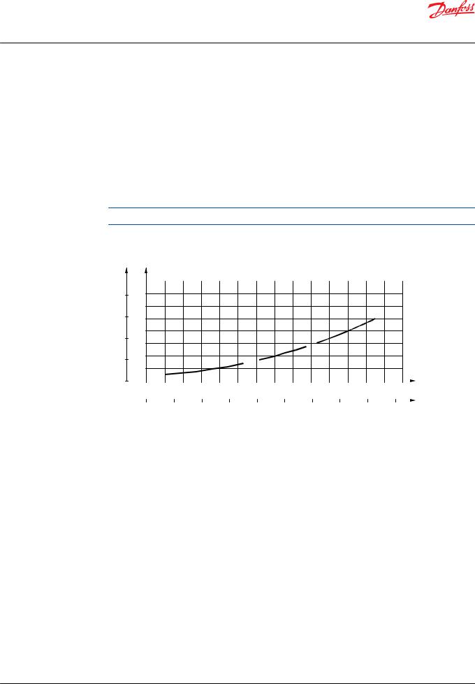
Pressure drop in motor
|
p |
p |
psi |
bar |
|
|
16 |
|
|
|
20014
12
150 10
8
100
6
504
2
0 |
0 |
|
|
|
|
|
|
|
|
|
|
|
|
|
Q |
|
|
|
|
|
|
|
|
|
|
|
|
|
|||
|
0 |
20 |
|
40 |
60 |
|
80 |
100 |
120 |
140 |
l/min |
||||
|
|
|
|
|
|
|
|
|
|
|
|
|
|
|
Q |
|
|
|
|
|
|
|
|
|
|
|
|
|
|
|
|
|
0 |
4 |
8 |
12 |
16 |
20 |
24 |
28 |
32 |
36 US gal/min |
|||||
|
|
|
|
|
|
|
|
|
|
|
|
|
151-1409.10 |
||
The curve applies to an unloaded motor shaft and an oil viscosity of 35 mm2/s [165 SUS] |
|
|
|||||||||||||
Oil flow in drain line |
|
|
|
|
|
|
|
|
|
|
|
||||
Maximum oil flow in the drain line at a return pressure less than 5-10 bar [75-150 psi] |
|
|
|
||||||||||||
|
|
|
|
|
|
|
|
|
|
|
|||||
Pressure drop |
|
|
|
Viscosity |
|
|
|
|
Oil flow in drain line |
||||||
|
|
|
|
|
|
|
|
|
|
|
|
|
|
|
|
bar |
|
|
|
[psi] |
|
|
mm2/s |
|
|
[SUS] |
|
l/min |
|
|
[US gal/min] |
140 |
|
|
|
[2030] |
|
|
20 |
|
|
[100] |
|
2.5 |
|
[0.66] |
|
|
|
|
|
|
|
|
|
|
|
|
|
|
|
|
|
|
|
|
|
|
|
|
35 |
|
|
[165] |
|
1.5 |
|
[0.40] |
|
|
|
|
|
|
|
|
|
|
|
|
|
|
|
|
|
210 |
|
|
|
[3050] |
|
|
20 |
|
|
[100] |
|
5.0 |
|
[1.32] |
|
|
|
|
|
|
|
|
|
|
|
|
|
|
|
|
|
|
|
|
|
|
|
|
35 |
|
|
[165] |
|
3.0 |
|
[0.79] |
|
|
|
|
|
|
|
|
|
|
|
|
|
|
|
|
|
12 | © Danfoss | September 2021 |
BC152886483862en-000801 |
Technical Information
OMT and OMV Orbital Motors
OMT
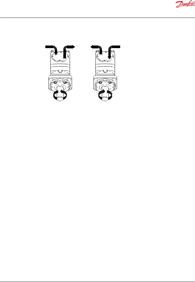
Direction of shaft rotation
B A B A
151-1050.10
Permissible shaft loads for OMT
Mounting flange:
Standard
Shaft:
All shaft types
Mounting flange:
Wheel
Shaft:
All shaft types
The output shaft runs in tapered roller bearings that permit high axial and radial forces.
The permissible radial load on the shaft is shown for an axial load of 0 N as a function of the distance from the mounting flange to the point of load application.
The curve is based on B10 bearing life (2000 hours or 12,000,000 shaft revolutions at 100 min-1) at rated output torque, when mineral-based hydraulic oil with a sufficient content of anti-wear additives, is used.
For 3,000,000 shaft revolutions or 500 hours – increase these shaft loads with 52%.
The dash curve shows maximum radial shaft load. Any shaft load exceeding the values shown in the curve will involve a risk of breakage.
Bearing life calculations can be made using the explanation and formula provided in the chapter "Bearing dimensioning in the technical information General Orbital Motors, BC152886483554.
Mounting flange:
Brake-wheel
Shaft:
All shaft types
© Danfoss | September 2021 |
BC152886483862en-000801 | 13 |
Technical Information
OMT and OMV Orbital Motors
OMT
Mounting flange:
Brake-standard
Shaft:
All shaft types
The output shaft runs in tapered roller bearings that permit high axial and radial forces.
The permissible radial load on the shaft is shown for an axial load of 0 N as a function of the distance from the mounting flange to the point of load application.
The curve is based on B10 bearing life (2000 hours or 12,000,000 shaft revolutions at 100 min-1) at rated output torque, when mineral-based hydraulic oil with a sufficient content of anti-wear additives, is used.
For 3,000,000 shaft revolutions or 500 hours – increase these shaft loads with 52%.
The dash curve shows max. radial shaft load. Any shaft load exceeding the values shown in the curve will involve a risk of breakage.
Bearing life calculations can be made using the explanation and formula provided in the chapter Bearing dimensioning in the technical information General Orbital Motors, BC152886483554.
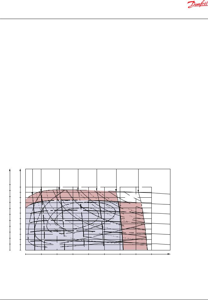
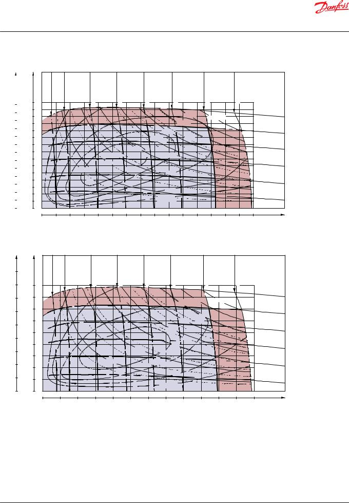
OMT Function diagrams
Continuous range |
|
|
|
Intermittent range (maximum 10% operation every minute) |
|
|
|
OMT 160 |
<![if ! IE]> <![endif]>40 l/min gal/min]US[10.6 |
|
<![if ! IE]> <![endif]>60 l/min gal/min]US[15.9 |
|
<![if ! IE]> <![endif]>80 l/min gal/min]US[21.1 |
<![if ! IE]> <![endif]>100l/min gal/min]US[26.4 |
|
<![if ! IE]> <![endif]>Q=125l/min gal/min]US[33.0 |
|
|
|
||
lbf• in |
<![if ! IE]> <![endif]>Q=10l/min |
<![if ! IE]> <![endif]>gal/min]US[2.6 |
<![if ! IE]> <![endif]>20 l/min gal/min]US[5.3 |
|
|
|
|
|
|
|||||
Nm |
|
|
|
|
|
|
|
|
|
|
|
|
|
|
5500 |
600 |
|
|
|
|
|
|
|
|
|
|
|
|
|
|
|
|
|
|
|
|
|
|
|
|
|
|
|
|
5000 |
550 |
|
|
|
|
|
|
|
|
|
|
|
p=240 |
bar |
|
|
|
|
|
|
|
|
|
|
|
|
|||
4500 |
500 |
|
|
|
|
|
|
|
|
N=35kW |
|
3480 psi |
||
|
|
|
|
|
|
|
|
|
|
|
||||
|
|
|
|
|
|
|
|
|
|
|
|
|
|
|
4000 |
450 |
|
|
|
|
|
|
|
|
|
|
|
200 |
bar |
3500 |
400 |
|
|
|
|
|
|
|
35hp |
30kW |
|
2900 |
psi |
|
|
|
|
|
|
|
|
|
|
|
|||||
|
|
|
|
|
|
|
|
25kW |
|
|
|
|
||
|
350 |
|
|
|
|
|
|
|
|
|
|
160 bar |
||
3000 |
|
|
|
|
|
|
|
|
|
|
|
|||
|
|
|
|
|
|
|
|
30hp |
|
|
2320 psi |
|||
|
|
|
|
|
|
|
|
|
|
|
||||
2500 |
300 |
|
|
|
|
|
|
|
25hp |
20kW |
|
|
|
|
|
|
|
|
|
|
|
|
|
|
|
|
120 bar |
||
|
250 |
|
|
|
|
|
|
|
20hp |
|
|
|
||
2000 |
|
|
ηt =86% |
|
|
|
|
15kW |
|
1740 psi |
||||
|
|
|
|
|
|
|
|
|
||||||
200 |
|
|
|
|
|
|
|
|
|
|
||||
|
|
|
|
|
|
|
|
10kW |
15hp |
|
|
|
|
|
1500 |
|
|
|
85% |
|
|
|
10hp |
|
|
80 bar |
|||
150 |
|
|
|
N=5kW |
|
|
|
|
|
|||||
|
|
|
5hp |
|
|
|
|
|
|
1160 psi |
||||
1000 |
|
|
|
|
|
|
|
|
|
|
||||
100 |
|
|
|
|
|
|
|
|
|
|
|
|
||
|
|
|
|
|
|
|
|
|
|
|
|
|
||
|
|
|
|
|
|
|
|
|
|
|
|
p= 40 bar |
||
500 |
50 |
|
|
80% |
|
|
|
|
|
|
|
|
||
|
|
|
|
|
|
|
|
|
|
580 psi |
||||
|
|
|
|
ηt =70% |
|
|
|
|
|
|
|
|
||
0 |
0 |
|
|
|
|
|
|
|
|
|
|
|
|
|
|
|
|
|
|
|
|
|
|
|
|
|
|
||
|
0 |
|
100 |
200 |
|
300 |
400 |
500 |
600 |
|
700 |
800 |
min-1 |
|
|
|
|
|
|
|
|
|
|
|
|
|
|
(rpm) |
|
|
|
|
|
|
|
|
|
|
|
|
|
|
151-493.10 |
|
14 | © Danfoss | September 2021 |
BC152886483862en-000801 |
Technical Information
OMT and OMV Orbital Motors
OMT
lbf• in |
|
Nm |
6500 |
|
750 |
|
700 |
|
6000 |
|
|
|
650 |
|
5500 |
|
|
|
600 |
|
|
|
|
5000 |
|
550 |
|
|
|
4500 |
|
500 |
4000 |
|
450 |
3500 |
|
400 |
3000 |
|
350 |
|
|
|
2500 |
|
300 |
|
250 |
|
2000 |
|
|
|
200 |
|
1500 |
|
|
|
150 |
|
|
|
|
1000 |
|
100 |
|
|
|
500 |
|
50 |
0 |
|
0 |
|
OMT 200
|
<![if ! IE]> <![endif]>Q=10 l/min [2.6 US gal/min] |
<![if ! IE]> <![endif]>20 l/min [5.3 US gal/min] |
<![if ! IE]> <![endif]>40 l/min [10.6 US gal/min] |
|
<![if ! IE]> <![endif]>60 l/min [15.9 US gal/min] |
|
<![if ! IE]> <![endif]>80 l/min [21.1 US gal/min] |
|
<![if ! IE]> <![endif]>100 l/min [26.4 US gal/min] |
|
<![if ! IE]> <![endif]>125 l/min [33.0 US gal/min] |
|
<![if ! IE]> <![endif]>Q=150 l/min [39.6 US gal/min] |
|
|
|
|
|
|
|
|
|
|
|
|
|
35kW |
|
|
|
|
p=240 bar |
|
|
|
|
|
|
|
|
|
|
|
N=40kW |
|
|
3480 psi |
|||
|
|
|
|
|
|
|
|
|
|
|
|
|
|
|||
|
|
|
|
|
|
|
|
|
|
30kW |
|
|
|
|
|
|
|
|
|
|
|
|
|
|
|
25kW |
|
|
|
|
|
|
200 bar |
|
|
|
|
|
|
|
|
|
|
|
|
|
|
|
2900 psi |
|
|
|
|
|
|
|
|
|
20kW |
35hp |
|
|
|
|
|||
|
|
|
|
|
|
|
|
40hp |
|
|
|
|
||||
|
|
|
|
|
|
15kW |
|
25hp |
30hp |
|
|
|
|
|
160 bar |
|
|
|
|
|
|
|
|
|
|
|
|
|
2320 psi |
||||
|
|
|
|
|
10kW |
|
20hp |
|
87% |
|
|
|
|
|
|
|
|
|
|
|
|
15hp |
|
|
|
|
|
|
|
|
|||
|
|
|
|
|
10hp |
ηt =88% |
|
|
|
|
|
|
|
|
120 bar |
|
|
|
|
N=5kW |
|
|
|
85% |
|
|
|
|
|
|
1740 psi |
||
|
|
|
|
|
|
|
|
|
|
|
|
|
||||
|
|
|
|
|
|
|
|
|
|
|
|
|
|
|
|
|
|
|
|
5hp |
|
|
|
|
|
|
|
|
|
|
|
|
80 bar |
|
|
|
|
|
|
|
|
|
80% |
|
|
|
|
|
|
1160 psi |
|
|
|
|
|
|
|
|
|
|
|
|
|
|
|
|
|
|
|
|
|
|
|
|
|
ηt =70% |
|
|
|
|
|
|
p= 40 bar |
|
|
|
|
|
|
|
|
|
|
|
|
|
|
|
580 psi |
||
|
|
|
|
|
|
|
|
|
|
|
|
|
|
|
|
|
0 |
50 |
100 |
150 |
200 |
250 |
300 |
350 |
400 |
450 |
500 |
550 |
600 |
650 |
700 |
750 |
min-1 |
|
|
|
|
|
|
|
|
|
|
|
|
|
|
|
|
(rpm) |
|
|
|
|
|
|
|
|
|
|
|
|
|
|
|
|
151-494.10 |
|
OMT 250 |
|
<![if ! IE]> <![endif]>40l/min gal/min]US[10.6 |
<![if ! IE]> <![endif]>60l/min gal/min]US.9[15 |
|
<![if ! IE]> <![endif]>80l/min gal/min]US[21.1 |
|
<![if ! IE]> <![endif]>100l/min gal/min]US[26.4 |
|
<![if ! IE]> <![endif]>125l/min gal/min]US[33.0 |
|
<![if ! IE]> <![endif]>Q=150l/min gal/min]US[39.6 |
|
|
|
||
lbf• in |
<![if ! IE]> <![endif]>Q=10l/min |
<![if ! IE]> <![endif]>gal/min]US[2.6 |
<![if ! IE]> <![endif]>20l/min gal/min]US[5.3 |
|
|
|
|
|
|
|
|
||||||
Nm |
|
|
|
|
|
|
|
|
|
|
|
|
|
|
|
|
|
9000 |
|
|
|
|
|
|
|
|
|
|
|
|
|
|
|
|
|
8000 |
900 |
|
|
|
|
|
|
|
|
|
|
|
|
|
|
|
|
|
800 |
|
|
|
|
|
|
|
|
|
|
|
|
|
|
p=240 bar |
|
7000 |
|
|
|
|
|
|
|
|
|
|
35kW |
N=40kW |
|
|
3480 psi |
||
|
|
|
|
|
|
|
|
|
|
|
30kW |
|
|
|
|
||
|
|
|
|
|
|
|
|
|
|
|
|
|
|
|
|
|
|
6000 |
700 |
|
|
|
|
|
|
|
|
|
|
|
|
|
|
200 bar |
|
|
|
|
|
|
|
|
|
|
|
|
|
|
|
|
|||
|
|
|
|
|
|
|
|
|
|
|
40hp |
|
|
|
2900 |
psi |
|
|
|
|
|
|
|
|
|
|
|
|
|
|
|
|
|||
|
600 |
|
|
|
|
|
|
|
|
|
25kW |
|
|
|
|
||
5000 |
|
|
|
|
|
|
|
|
|
35hp |
|
|
|
|
|
||
|
|
|
|
|
|
|
|
|
|
|
|
|
|
|
160 bar |
||
|
500 |
|
|
|
|
|
|
|
|
20kW |
30hp |
|
|
|
|||
|
|
|
|
|
|
|
|
|
|
|
|
2320 psi |
|||||
4000 |
|
|
|
|
|
|
|
15kW |
|
|
|
|
|
||||
|
|
|
|
|
|
|
|
25hp |
|
|
|
|
|
|
|||
|
400 |
|
|
|
|
|
|
|
15hp |
20hp |
|
|
|
|
120 bar |
||
|
|
|
|
|
|
|
|
|
|
|
|
|
|
|
1740 |
|
|
3000 |
|
|
|
|
|
|
|
10kW |
ηt =87% |
|
|
|
|
|
psi |
||
|
|
|
|
|
|
|
|
|
|
|
|
|
|||||
300 |
|
|
|
|
|
|
|
|
|
|
|
|
|
|
|||
|
|
|
|
|
|
|
|
|
|
|
|
|
|
|
|
|
|
2000 |
|
|
|
|
|
N=5kW |
|
10hp |
85% |
|
|
|
|
|
80 bar |
||
200 |
|
|
|
|
|
|
|
|
|
|
|
1160 psi |
|||||
|
|
|
|
|
5hp |
|
|
|
|
|
|
|
|
|
|||
1000 |
|
|
|
|
|
|
|
|
80% |
|
|
|
|
|
|
||
100 |
|
|
|
|
|
|
|
|
|
|
|
|
p= 40 bar |
||||
|
|
|
|
|
|
|
ηt =70% |
|
|
|
|
|
|||||
|
|
|
|
|
|
|
|
|
|
|
|
|
|||||
|
|
|
|
|
|
|
|
|
|
|
|
|
|
580 |
psi |
||
|
|
|
|
|
|
|
|
|
|
|
|
|
|
|
|||
0 |
0 |
|
|
|
|
|
|
|
|
|
|
|
|
|
|
|
|
|
0 |
|
50 |
100 |
150 |
200 |
250 |
300 |
|
350 |
400 |
450 |
500 |
550 |
600 |
min-1 |
|
|
|
|
|
|
|
|
|
|
|
|
|
|
|
|
|
(rpm) |
|
|
|
|
|
|
|
|
|
|
|
|
|
|
|
|
|
151-495.10 |
|
© Danfoss | September 2021 |
BC152886483862en-000801 | 15 |

Technical Information
OMT and OMV Orbital Motors
OMT
lbf• in |
|
Nm |
11000 |
|
1200 |
|
|
|
10000 |
|
1100 |
|
|
|
9000 |
|
1000 |
|
|
|
8000 |
|
900 |
7000 |
|
800 |
6000 |
|
700 |
|
|
|
5000 |
|
600 |
|
|
|
4000 |
|
500 |
|
400 |
|
|
|
|
3000 |
|
300 |
|
|
|
2000 |
|
200 |
|
|
|
1000 |
|
100 |
0 |
|
0 |
|
OMT 315
| <![if ! IE]> <![endif]>Q=10 l/min [2.6 US gal/min] |
<![if ! IE]> <![endif]>20 l/min [5.3 US gal/min] |
<![if ! IE]> <![endif]>40 l/min [10.6 US gal/min] |
<![if ! IE]> <![endif]>60 l/min [15.9 US gal/min] |
|
<![if ! IE]> <![endif]>80 l/min [21.1 US gal/min] |
|
<![if ! IE]> <![endif]>100 l/min [26.4 US gal/min] |
|
|
<![if ! IE]> <![endif]>125 l/min [33.0 US gal/min] |
<![if ! IE]> <![endif]>Q=150 l/min [39.6 US gal/min] |
|
|
|
|
|
|
|
|
|
|
|
|
|
|
|
|
|
|
p=240 bar |
|
|
|
|
|
|
|
|
|
|
35kW |
N=40kW |
|
|
3480 psi |
||
|
|
|
|
|
|
|
|
|
|
|
|
|
|||
|
|
|
|
|
|
|
|
|
30kW |
|
|
|
200 bar |
||
|
|
|
|
|
|
|
|
|
|
|
|
2900 psi |
|||
|
|
|
|
|
|
|
|
25kW |
|
40hp |
|
|
|||
|
|
|
|
|
|
|
|
|
|
|
|
|
|||
|
|
|
|
20hp |
|
|
|
|
|
|
|
160 bar |
|||
|
|
|
|
20kW |
|
30hp |
35hp |
|
|
|
|||||
|
|
|
|
|
15kW |
|
|
|
|
2320 psi |
|||||
|
|
|
|
15hp |
|
25hp |
|
|
|
||||||
|
|
|
|
|
|
|
|
|
|
|
|
|
|||
|
|
|
|
10kW |
|
|
|
|
|
|
|
|
120 bar |
||
|
|
|
10hp |
|
|
|
|
|
|
|
|
1740 psi |
|||
|
|
|
|
|
|
|
|
|
|
|
|
|
|||
|
|
|
|
|
|
|
|
|
|
|
|
|
|
|
|
|
|
5hp |
N=5kW |
|
87% |
|
|
|
|
|
|
|
|
80 bar |
|
|
|
|
ηt =88% |
|
|
|
|
|
|
|
|
|
1160 |
psi |
|
|
|
|
|
|
|
|
|
|
|
|
|
|
|||
|
|
|
|
|
|
|
|
|
|
|
|
|
|
||
|
|
|
85% |
|
80% |
|
|
|
|
|
|
|
|
p= 40 bar |
|
|
|
|
ηt =70% |
|
|
|
|
|
|
|
|
|
|
580 psi |
|
|
|
|
|
|
|
|
|
|
|
|
|
|
|
|
|
0 |
50 |
100 |
150 |
200 |
250 |
|
300 |
|
350 |
400 |
450 |
500 |
min-1 |
||
|
|
|
|
|
|
|
|
|
|
|
|
|
|
(rpm) |
|
|
|
|
|
|
|
|
|
|
|
|
|
|
|
151-869.10 |
|
OMT 400
lbf• in |
Nm |
<![if ! IE]> <![endif]>Q=10l/min [2.6 USgal/min] |
<![if ! IE]> <![endif]>20l/min [5.3 USgal/min] |
<![if ! IE]> <![endif]>40l/min [10.6 USgal/min] |
|
<![if ! IE]> <![endif]>60l/min [15.9 USgal/min] |
|
<![if ! IE]> <![endif]>80l/min [21.1 USgal/min] |
|
<![if ! IE]> <![endif]>100l/min [26.4 USgal/min] |
|
<![if ! IE]> <![endif]>125l/min [33.0 USgal/min] |
|
<![if ! IE]> <![endif]>Q=150l/min [39.6 USgal/min] |
|
|
|
|
|
12000 |
1300 |
|
|
|
|
|
|
|
|
|
|||||||||
|
|
|
|
|
|
|
|
|
|
||||||||||
11000 |
|
|
|
|
|
|
|
|
|
|
|
|
|
|
|
|
|
|
|
1200 |
|
|
|
|
|
|
|
|
|
|
|
|
|
|
|
p=210 bar |
|||
|
|
|
|
|
|
|
|
|
|
|
|
|
|
|
|
||||
10000 |
1100 |
|
|
|
|
|
|
|
|
|
|
|
|
|
|
|
3050 |
psi |
|
|
|
|
|
|
|
|
|
|
|
|
|
|
|
|
|
|
|||
|
|
|
|
|
|
|
|
|
|
|
|
|
|
|
|
|
|
|
|
9000 |
1000 |
|
|
|
|
|
|
|
|
|
|
|
|
|
|
|
180 |
bar |
|
|
|
|
|
|
|
|
|
|
|
|
|
|
|
|
|
2610 psi |
|||
|
|
|
|
|
|
|
|
|
|
|
|
|
|
N=30kW |
|
|
|||
8000 |
900 |
|
|
|
|
|
|
|
|
|
|
|
|
|
|
150 bar |
|||
|
|
|
|
|
|
|
|
|
|
|
|
25kW |
|
|
|
|
|||
7000 |
800 |
|
|
|
|
|
|
|
|
|
|
|
|
|
|
2180 psi |
|||
|
|
|
|
|
|
|
|
|
|
20kW |
|
|
|
|
|||||
6000 |
700 |
|
|
|
|
|
|
|
|
|
|
|
|
|
|
|
|
|
|
|
|
|
|
|
|
|
|
15kW |
|
|
|
|
|
|
120 bar |
||||
|
|
|
|
|
|
10kW |
|
|
25hp |
|
30hp |
|
|
||||||
5000 |
600 |
|
|
|
|
10hp |
|
87% |
|
|
|
|
1740 psi |
||||||
500 |
|
|
|
|
|
ηt =89% |
|
20hp |
|
|
|
|
|
|
|
||||
4000 |
|
|
|
5kW |
|
15hp |
|
|
|
|
|
|
90 bar |
||||||
|
|
|
5hp |
|
|
|
|
|
|
|
|||||||||
400 |
|
|
|
|
|
|
|
|
|
|
|
|
1300 psi |
||||||
|
|
|
|
|
|
|
|
85% |
|
|
|
|
|
|
|||||
|
|
|
|
|
|
|
|
|
|
|
|
|
|
|
|
|
|
||
3000 |
|
|
|
|
|
|
|
|
|
|
|
|
|
|
|
|
|
|
|
300 |
|
|
|
|
|
|
|
|
|
|
|
|
|
|
|
60 bar |
|||
|
|
|
2.5hp |
|
|
|
|
|
80% |
|
|
|
|
|
|
||||
2000 |
200 |
|
|
N=2.5kW |
|
|
|
|
|
|
|
|
|
870 psi |
|||||
|
|
|
|
|
|
|
|
|
|
|
|
|
|||||||
|
|
|
|
|
|
|
|
|
|
|
|
|
|
|
|
||||
1000 |
100 |
|
|
|
|
|
|
|
ηt =70% |
|
|
|
|
|
|
p= 30 bar |
|||
0 |
0 |
|
|
|
|
|
|
|
|
|
|
|
|
|
440 psi |
||||
|
|
|
|
|
|
|
|
|
|
|
|
|
|
|
|
|
|
||
|
|
|
|
|
|
|
|
|
|
|
|
|
|
|
|
|
|
|
|
|
0 |
25 |
50 |
75 |
100 |
125 |
150 |
175 |
200 |
225 |
250 |
275 |
300 |
325 |
350 |
375 |
min-1 |
||
|
|
|
|
|
|
|
|
|
|
|
|
|
|
|
|
|
(rpm) |
||
|
|
|
|
|
|
|
|
|
|
|
|
|
|
|
|
|
151-1058.10 |
||
16 | © Danfoss | September 2021 |
BC152886483862en-000801 |
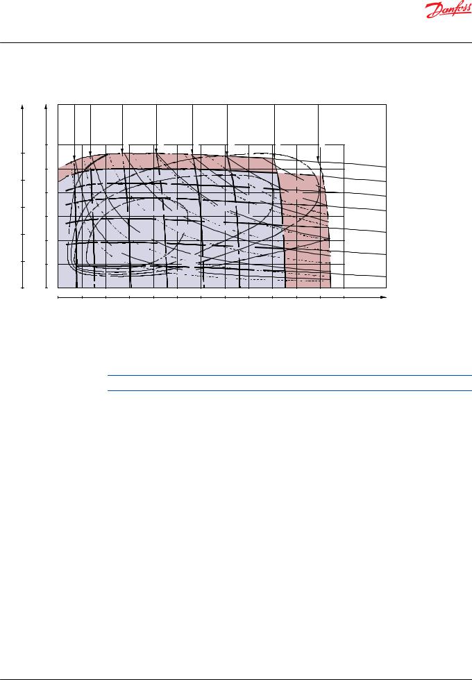
Technical Information
OMT and OMV Orbital Motors
OMT
|
OMT 500 |
|
<![if ! IE]> <![endif]>40 l/min US[10.6gal/min] |
<![if ! IE]> <![endif]>60 l/min US[15.9gal/min] |
<![if ! IE]> <![endif]>80 l/min US[21.1gal/min] |
|
<![if ! IE]> <![endif]>100l/min US[26.4gal/min] |
|
<![if ! IE]> <![endif]>125l/min US[33.0gal/min] |
|
<![if ! IE]> <![endif]>Q=150l/min US[39.6gal/min] |
|
|
|
|
||
lbf• in |
<![if ! IE]> <![endif]>Q=10l/min |
<![if ! IE]> <![endif]>US[2.6gal/min] |
<![if ! IE]> <![endif]>20 l/min US[5.3gal/min] |
|
|
|
|
|
|
|
|
||||||
Nm |
|
|
|
|
|
|
|
|
|
|
|
|
|
|
|
|
|
|
1500 |
|
|
|
|
|
|
|
|
|
|
|
|
|
|
|
|
12500 |
|
|
|
|
|
|
|
|
|
|
|
|
|
|
|
|
|
|
|
|
|
|
|
|
|
|
|
|
|
|
|
|
p=180 bar |
||
|
1250 |
|
|
|
|
|
|
|
|
|
|
|
|
|
2610 |
psi |
|
|
|
|
|
|
|
|
|
|
|
|
|
|
|
|
|
||
10000 |
|
|
|
|
|
|
|
|
|
30hp |
|
N=30kW |
|
160 bar |
|||
|
|
|
|
|
|
|
|
|
|
|
2320 psi |
||||||
|
1000 |
|
|
|
|
|
|
|
|
|
|
25kW |
|
|
140 bar |
||
|
|
|
|
|
|
|
|
|
20kW |
|
|
2030 psi |
|||||
|
|
|
|
|
|
|
|
|
|
|
|
||||||
7500 |
|
|
|
|
|
|
|
|
15kW |
|
25hp |
|
|
|
120 bar |
||
|
|
|
|
|
10hp |
10kW |
|
|
|
|
|
1740 |
psi |
||||
|
750 |
|
|
|
|
|
|
|
|
|
|
|
|||||
|
|
|
|
|
|
|
20hp |
|
|
|
|
|
|
||||
|
|
|
|
|
|
|
|
|
|
|
|
|
|
|
|
||
|
|
|
|
|
|
|
ηt =90% |
|
|
|
|
|
|
|
|
|
|
|
|
|
|
|
|
|
|
15hp |
|
|
|
|
|
90 |
bar |
||
5000 |
500 |
|
|
|
|
5kW |
|
|
|
|
|
|
|
|
1300 psi |
||
|
|
|
|
|
|
|
|
|
|
|
|
|
|
|
|||
|
|
|
|
|
5hp |
|
|
|
|
|
|
|
|
|
|
|
|
|
|
|
|
N=2.5kW |
|
|
|
|
|
|
|
|
60 bar |
||||
|
|
|
|
|
|
|
|
|
|
|
|
|
|||||
2500 |
|
|
|
|
2.5hp |
|
87% |
|
|
|
|
|
|
|
870 |
psi |
|
250 |
|
|
|
|
|
85% |
|
|
|
|
|
|
|
|
|
|
|
|
|
|
|
|
|
|
|
|
|
|
|
|
|
|
|
||
|
|
|
|
|
|
|
ηt =80% |
|
|
|
|
|
|
|
p= 30 bar |
||
|
|
|
|
|
|
|
|
|
|
|
|
|
|
|
440 psi |
||
0 |
0 |
|
|
|
|
|
|
|
|
|
|
|
|
|
|
|
|
|
0 |
|
25 |
50 |
75 |
100 |
125 |
150 |
175 |
200 |
225 |
250 |
275 |
300 |
min-1 |
||
|
|
|
|
|
|
|
|
|
|
|
|
|
|
|
(rpm) |
||
|
|
|
|
|
|
|
|
|
|
|
|
|
|
|
151-1116.10 |
||
Function diagram use
Explanation of function diagram use, basis and conditions, see Speed, torque, and output on page 7.
Intermittent pressure drop and oil flow must not occur simultaneously.
© Danfoss | September 2021 |
BC152886483862en-000801 | 17 |
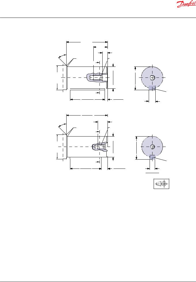
Technical Information
OMT and OMV Orbital Motors
OMT
Shaft version
|
82 [3.23] |
|
|
|
|
|
|
|
26 [1.02] |
|
|
|
|
|
|
9.5 [0.374] |
|
|
|
|
|
45˚ |
|
|
|
|
|
|
R0.5 [0.020] |
M12 |
|
|
A-A |
|
|
|
A |
|
|
|
|
|
|
<![if ! IE]> <![endif]>Ø40.002[1.5749] |
|
|
|
|
A |
<![if ! IE]> <![endif]>Ø45[1.77] |
<![if ! IE]> <![endif]>Ø40.018[1.5755] |
<![if ! IE]> <![endif]>43.00[1.693] |
<![if ! IE]> <![endif]>42.71[1.681] |
||
|
|
|
|
|
|
|
|
|
A |
|
|
|
C |
|
|
|
|
|
|
|
|
70.5 [2.776] |
|
5.5 [0.217] |
|
|
|
|
70.0 [2.756] |
|
4.5 [0.177] |
|
|
|
|
|
|
|
|
|
12.000 [0.4724] |
|
|
|
|
|
|
11.957 [0.4707] |
|
82.2 [3.236] |
|
|
|
|
|
|
81.8 [3.220] |
|
|
|
|
|
|
|
min. 20 [0.78] |
|
|
|
|
|
45˚ |
|
|
|
|
|
|
R0.5 [0.020] |
3/8 -16 UNC |
|
|
A-A |
|
|
|
A |
|
|
|
|
|
|
|
|
|
|
|
B |
<![if ! IE]> <![endif]>Ø45[1.77] |
<![if ! IE]> <![endif]>Ø38.10[1.500] |
<![if ! IE]> <![endif]>Ø38.05[1.498] |
<![if ! IE]> <![endif]>42.40[1.669] |
<![if ! IE]> <![endif]>42.14[1.659] |
|
|
|
|
|
|
|
|
|
|
A |
|
|
|
D |
|
|
|
|
|
|
|
|
57.5 [2.264] |
|
11.5 [0.453] |
|
|
|
|
56.9 [2.240] |
|
9.3 [0.366] |
|
|
9.545 [0.3758] |
|
|
|
|
|
|
|
|
|
|
|
|
|
9.525 [0.3750] |
|
|
|
151-1032.10 |
A |
Cylindrical 40 mm shaft |
B |
Cylindrical 1.5 in shaft |
C |
Parallel key |
D |
Parallel key |
|
A12 × 8 × 70 |
|
3/8 × 3/8 × 21/4 in |
|
DIN 6885 |
|
B.S. 46 |
|
Keyway deviates from standard |
|
Keyway deviates from standard |
18 | © Danfoss | September 2021 |
BC152886483862en-000801 |
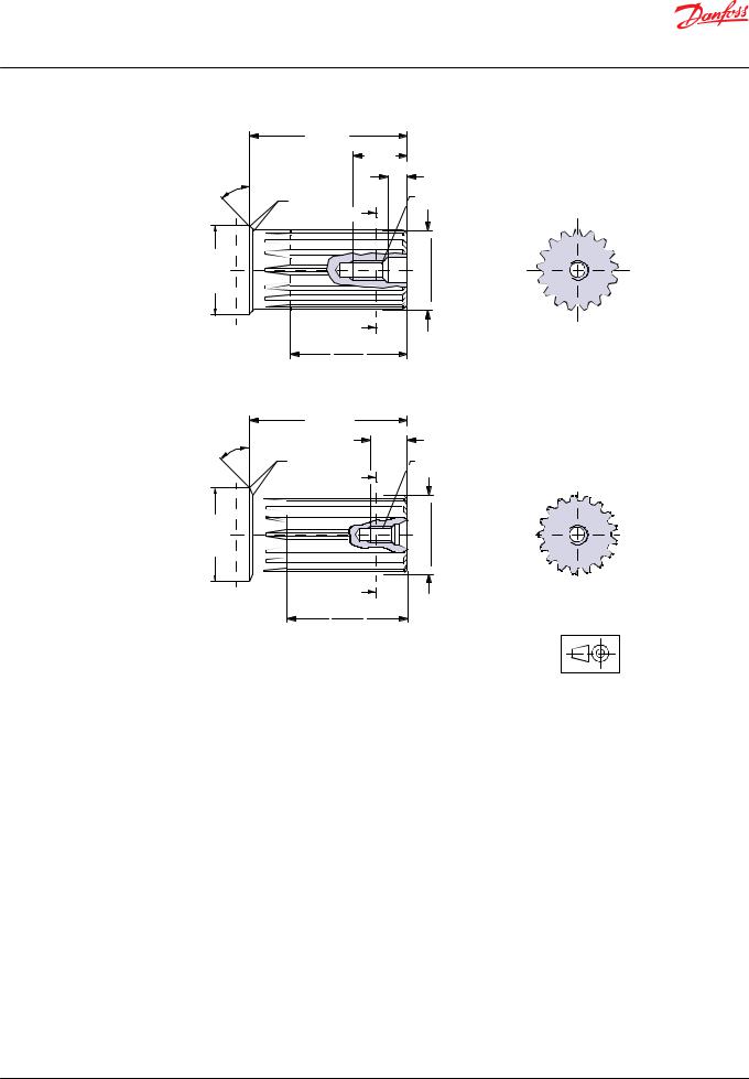
Technical Information
OMT and OMV Orbital Motors
OMT
|
82 [3.23] |
|
|
|
|
|
26 [1.02] |
|
|
|
|
9.5 [0.374] |
|
|
|
45˚ |
|
|
|
|
R0.5 [0.020] |
M12 |
A-A |
|
|
|
|
||
|
A |
<![if ! IE]> <![endif]>Ø38.100[1.5000] |
<![if ! IE]> <![endif]>Ø38.075[1.4990] |
|
C |
<![if ! IE]> <![endif]>Ø45[1.77] |
|
||
|
|
|
|
|
|
A |
|
|
|
|
58 [2.28] |
|
|
|
|
56 [2.20] |
|
|
|
|
82.2 [3.236] |
|
|
|
|
81.8 [3.220] |
min. 20 [0.78] |
|
|
|
|
|
|
|
|
45˚ |
|
|
|
|
R0.5 [0.020] |
3/8 -16 UNC |
|
|
|
A |
<![if ! IE]> <![endif]>Ø38.100[1.5000] |
<![if ! IE]> <![endif]>Ø38.075[1.4990] |
A-A |
D |
<![if ! IE]> <![endif]>Ø45[1.77] |
|
||
|
|
|
|
|
|
A |
|
|
|
|
58 [2.28] |
|
|
|
|
56 [2.20] |
|
|
|
151-1916.10
C |
Involute splined shaft |
D |
US version |
|
ANS B92.1 - 1970 standard |
|
Involute splined shaft |
|
Flat root side fit |
|
ANS B92.1 - 1970 standard |
|
Pitch 12/24 |
|
Flat root side fit |
|
Teeth 17 |
|
Pitch 12/24 |
|
Major diameter 1.50 in |
|
Teeth 17 |
|
Pressure angle 30° |
|
Major diameter 1.50 in |
|
|
|
Pressure angle 30° |
© Danfoss | September 2021 |
BC152886483862en-000801 | 19 |
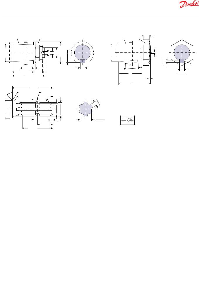
Technical Information
OMT and OMV Orbital Motors
OMT
|
H |
|
|
I |
|
|
|
|
|
| <![if ! IE]> <![endif]>[1.77]Ø45 |
|
A |
|
<![if ! IE]> <![endif]>[0.24]Ø6 |
<![if ! IE]> <![endif]>[0.28]Ø7 M30x2 |
<![if ! IE]> <![endif]>[2.20]Ø56 |
<![if ! IE]> <![endif]>[0.951]24.15 |
<![if ! IE]> <![endif]>[0.943]23.95 |
|
|
|
|
|||||||
E |
|
|
|
|
|
|
|
|
|
|
|
A |
|
|
|
|
|
|
|
|
|
34 [1.34] |
|
4 [0.16] |
|
|
|
|
|
|
54 [2.13] |
22 [0.87] |
|
|
|
|
|
||
|
|
82 [3.23] |
|
|
|
|
|
|
|
|
|
102 [4.02] |
|
|
|
|
|
|
|
45˚ |
R0.5 |
[0.020] |
|
R6.7 [0.267] |
|
|
|
|
|
|
|
|
|
|
|
|
|||
|
R5 [0.20] |
|
60˚ |
|
|
|
|
|
|
|
|
A |
|
|
|
|
|
|
|
|
|
|
|
|
|
|
|
|
|
| <![if ! IE]> <![endif]>Ø45[1.77] |
|
|
|
|
<![if ! IE]> <![endif]>[1.161]29.5 |
|
<![if ! IE]> <![endif]>[1.372] |
|
|
|
|
|
|
|
<![if ! IE]> <![endif]>Ø34.85 [1.367]Ø34.73 |
|
|
||
G |
|
|
|
|
|
<![if ! IE]> <![endif]>[1.154] |
|
|
|
|
|
|
|
|
|
<![if ! IE]> <![endif]>29.3 |
|
|
|
|
|
A |
|
7 [0.28] |
|
|
|
|
|
|
|
|
|
38.25 [1.506] |
|
|
|
|
|
|
|
77 [3.03] |
37.75 [1.486] |
|
|
|
|
|
|
|
|
|
|
|
|
|
|
||
|
|
75 [2.95] |
|
|
|
|
|
|
|
A-A
F |
<![if ! IE]> <![endif]>[1.77] |
|
| <![if ! IE]> <![endif]>Ø45 |
||
|


 J
J
12.000 [0.4724]
11.957 [0.4707]
A-A |
8 . |
|||
|
|
|
8 |
|
|
|
|
. 64 |
|
|
|
|
53 |
[0 |
|
|
|
[0 . |
|
|
|
|
. |
|
|
|
|
|
340] |
|
|
|
336] |
|
28.14 [1.108]**
27.89 [1.098]
K |
L |
16 [0.63] |
|
A-A |
|
|
|
|
|
||
A |
|
|
|
|
|
|
|
<![if ! IE]> <![endif]>Ø4 [0.16] |
<![if ! IE]> <![endif]>[0.225] |
<![if ! IE]> <![endif]>[0.221] |
|
A |
|
|
<![if ! IE]> <![endif]>5.71 5.61 |
M |
|
[1.264] |
|
|
|
|
|
32.1 |
|
|
|
|
|
31.5 |
[1.240] |
|
|
|
11.150 [0.4390] |
59.00 [2.323] |
|
|
|
||
57.80 [2.276] |
|
|
|
11.130 [0.4382] |
|
|
|
|
|
4.5 [0.177] |
|
|
|
|
|
|
|
||
80.8 [3.181] |
|
|
|
|
80.0 [3.150] |
|
|
|
|
151-1917.10
E |
Tapered 45 mm shaft (ISO/R775) |
F |
Tapered 1.75 in shaft |
G P.t.o. shaft |
I |
DIN 937 |
K |
Cone 1:8 |
DIN 9611 Form 1 (ISO/R500 |
|
Across flats: 46 mm |
|
SAE J501 |
without pin hole) |
|
|
** Deviates from DIN 9611 |
||
|
Tightening torque: 500 ± 30 Nm [4430 |
L |
1 1/4 - 18 UNEF |
|
|
|
|||
|
±270 lbf·in] |
|
Across flats 2 3/16 in |
|
H |
Taper 1:10 |
|
|
|
|
Tightening torque: 500 ±10 Nm (4425 ±90 |
|
||
|
|
|
|
|
J |
Parallel key |
|
lbf·in) |
|
|
B12 × 8 × 28 |
M Parallel key |
|
|
|
DIN 6885 |
|
7/16 × 7/16 × 1 1/4 |
|
|
Keyway deviates from standard |
|
B.S. 46 |
|
|
|
|
Keyway deviates from standard |
|
20 | © Danfoss | September 2021 |
BC152886483862en-000801 |
Technical Information
OMT and OMV Orbital Motors
OMT
Port thread versions
A
 E
E  [0.67]18


<![endif]>min.
C |
G |
| <![if ! IE]> <![endif]>min. 12 [0.47] |
A G main ports
E ISO 228/1 - G3/4
O-ring boss port
C G drain port
G G: ISO 228/1 - G1/4
O-ring boss port
B
Ø41.5 [1.634] Ø41.0 [1.614]
F
<![if ! IE]><![endif]>min. 19 [0.75]
D
H |
| <![if ! IE]> <![endif]>min. 13[0.51] |
151-1977.11
B UN main ports
F 1 1/16 - 12 UN
D UNF drain port
H 9/16 - 18 UNF
© Danfoss | September 2021 |
BC152886483862en-000801 | 21 |
 Loading...