

Page 1
Installation Guide
Pressure regulating valve
OFV, OFV-SS 20-25 (52 bar version)
Installation
148R 9537
1
2
148R 9537
Nm LB-feet
DN 20 18 13
DN 25 18 13
3
4
© Danfoss A/S (MWA), 2015-02 DKRCI.PI.HX0.A4.02 / 520H0768 1
Page 2
Maintenance
5 6
7 8
Nm LB-feet
DN 20 50 37
DN 25 50 37
9
23
10
11
2 DKRCI.PI.HX0.A4.02 / 520H0768 © Danfoss A/S (MWA), 2015-02
23
Page 3

ENGLISH
Installation
Refrigerants
Applicable to HCFC, HFC, R717(Ammonia)
and R744 (CO2).
Flammable hydrocarbons are not
recommended. The valve is only
recommended for use in closed circuits. For
further information please contact Danfoss.
Temperature range
OFV: –50/+150°C (–58/+302°F)
OFV-SS: –60/+150°C (–76/+302°F)
Pressure range
The valves are designed for a max. working
pressure of 52 bar g (554 psi g).
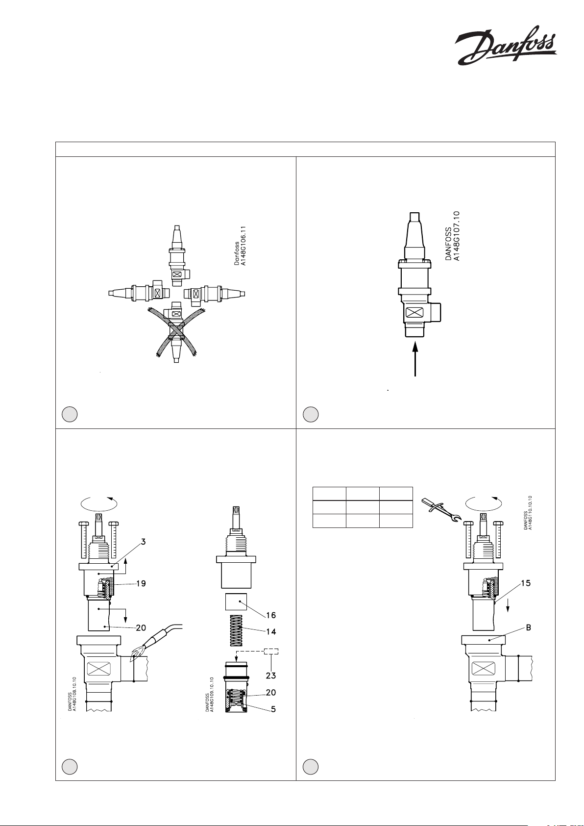
Installation
The valve must be installed with the
spindle vertically upwards or in horizontal
position (g. 1). Valves should be opened
by hand according to the guidelines
in the datasheet. The valve is designed
to withstand a high internal pressure.
However, the piping system should be
designed to avoid liquid traps and reduce
the risk of hydraulic pressure caused by
thermal expansion. It must be ensured
that the valve is protected from pressure
transients like “liquid hammer” in the
system.
Recommended ow direction
Direct the ow towards the cone as
indicated by the arrow placed on the valve
housing (g. 2). The force used to open and
close the valve must not exceed the force
of an ordinary handwheel.
Welding
The bonnet should be removed before
welding (g. 3) to prevent damage to
the O-rings in the packing gland and
between the valve body and bonnet, as
well as the teon gasket in the valve seat.
Only materials and welding methods,
compatible with the valve housing
material, must be welded to the valve
housing. The valve should be cleaned
internally to remove welding debris on
completion of welding and before the
valve is reassembled.
Avoid welding debris and dirt in the
threads of the housing and the bonnet.
Removing the bonnet can be omitted
provided that:
The temperature in the area between the
valve body and bonnet during welding
does not exceed +150°C/+302°F. This
temperature depends on the welding
method as well as on any cooling of the
valve body during the welding itself.
(Cooling can be ensured by, for example,
wrapping a wet cloth around the valve
body.)
Make sure that no dirt, welding debris
etc. get into the valve during the welding
procedure.
Be careful not to damage the teon cone
ring.
The valve housing must be free from
stresses (external loads) after installation.
Opening pressure
From factory the OFV will be covering
dierential pressure (∆P) 2-6.5 bar (29-94.3
psig).
Adjust the dierential pressure by turning
the spindle as shown in g. 11. If the above
range is satisfactory please continue with
“Assembly”.
Alternatively, by mounting the distance
piece, (pos. 23) the following range can be
obtained: ∆P = 3.5-8 bar (50.8-116 psig).
Mounting of distance piece (g. 3)
Valve bonnet and guide are held together
by O-ring (pos. 19). Separate the bonnet
(pos. 3) and the guide (pos. 20) by
pulling the pieces from each other. Now
springshoe (pos. 16) and spring (pos. 14)
can be removed. Then mount the distance
piece (pos. 23), supplied separately
together with the installation instruction,
in the cone (pos. 5) at the bottom of the
guide (pos. 20).
NB: Do not take cone and guide apart.
OFV valves must not be mounted in
systems where the outlet side of the valve
is open to atmosphere. The outlet side of
the valve must always be connected to the
system or properly capped o, for example
with a welded-on end plate.
Assembly
Remove welding debris and any dirt from
pipes and valve body before assembly.
Check that the cone has been fully screwed
back towards the bonnet before it is
replaced in the valve body (g. 4).
Tightening
Tighten the bonnet with a torque wrench,
to the values indicated in the table (g. 4).
Colours and identication
The OFV valves are painted with a red oxide
primer in the factory. Stainless steel valves
are not painted. Precise identication of
the valve is made via the ID ring at the top
of the bonnet, as well as by the stamping
on the valve body. The external surface of
the painted OFV valve housing must be
prevented against corrosion with a suitable
protective coating after installation and
assembly.
Protection of the ID ring when repainting
the valve is recommended.
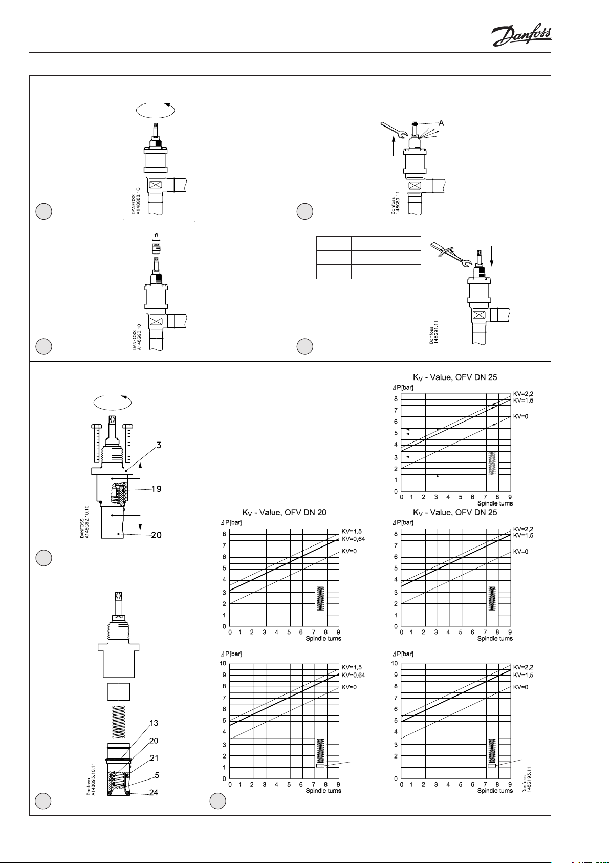
Maintenance
Packing gland
When performing service and maintenance, replace the complete packing gland
only, which is available as a spare part.
As a general rule, the packing gland must
not be removed if there is internal pressure
in the valve.
However, if the following precautionary
measures are taken, the packing gland
can be removed with the valve still under
pressure:
Backseating (g. 5)
To backseat the valve, turn the spindle
counter-clockwise until the valve is fully
open.
Pressure equalization (g. 6)
In some cases, pressure forms behind
the packing gland. Hence a handwheel
or similar should be fastened on top of
the spindle (pos. A) while the pressure is
equalized. The pressure can be equalized
by slowly screwing out the gland.
Removal of packing gland (g. 7)
Cap and packing gland can now be
removed.
Dismantling the valve (g. 10)
Do not remove the bonnet while the valve
is still under pressure.
- Check that the O-rings (pos. 13 & 24)
have not been damaged.
- Check that spindle and cone (pos. 5) are
free of scratches and impact marks.
- If the sealing ring (pos. 21) has been
damaged, the whole cone assembly
must be inspected carefully and maybe
replaced.
Replacement of O-ring (g. 10)
O-ring (pos. 24) seals between seat and
cone. Therefore, it has to be changed if
the valve is leaking. Use a pointed tool to
dismount the O-ring (pos. 24). Check that
cone (pos. 5) and guide (pos. 20) are not
worn out. If these parts are worn out it is
necessary to change the complete guide
which consists of all wearing parts.
Assembly
Remove any dirt from the body before the
valve is assembled. Check that the cone
has been screwed back towards the bonnet
before it is replaced in the valve body (g.
4).
Tightening
Tighten the bonnet with a torque wrench,
to the values indicated in the table (g. 4).
Tighten the packing gland with a torque
wrench, to the values indicated in the table
(g. 6).
Use only original Danfoss parts, including
packing glands, O-rings and gaskets for
replacement. Materials of new parts are
certied for the relevant refrigerant. In
cases of doubt, please contact Danfoss.
Danfoss accepts no responsibility for
errors and omissions. Danfoss Industrial
Refrigeration reserves the right to make
changes to products and specications
without prior notice.
© Danfoss A/S (MWA), 2015-02 DKRCI.PI.HX0.A4.02 / 520H0768 3
Page 4

4 DKRCI.PI.HX0.A4.02 / 520H0768 © Danfoss A/S (MWA), 2015-02
 Loading...