

Page 1
Data Sheet
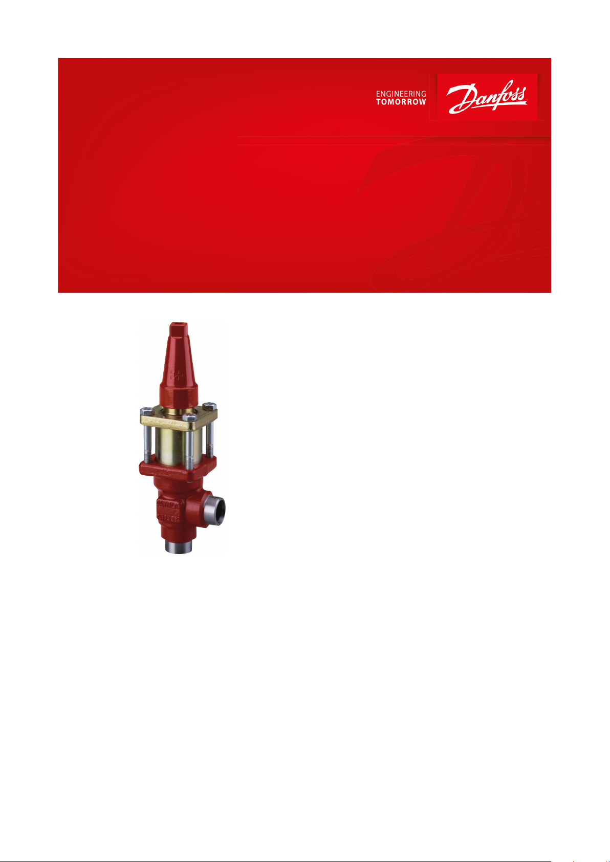
Pressure regulating valve
Type OFV and OFV-SS 20-25
Ecient control of defrosting pressure
OFV are angle-way pressure regulating valves,
which have ajustable opening pressure and
cover the dierential pressure range (ΔP): 2 - 8
bar (29 ‑ 116 psi). The valve can be closed
manually, e.g. during plant service and have
backseating, enabling the spindle seal to be
replaced with the valve still under pressure.
The valves are especially designed to prevent
uttering due to low velocity and/or low
density. In consequence it is possible to apply
the valves with wide uctuations in capacity
demands, i.e. from maximum performance to
part load. A exible O-ring provides perfect
sealing over the seat.
Features
• Applicable to HCFC, HFC, R717(Ammonia)
and R744 (CO2).
• Full temperature range packing gland -50 °C /
+150 °C (-58 °F / +302 °F)
• Maximum operating pressure: 40 bar (580
psig)
• Three functions in one valve. The OFV valve
combines the functions of a pressure
reegulating valve, a check valve and a shut-
o valve
• Classication: DNV, CRN, BV, EAC etc. To get
an updated list of certication on the
products please contact your local Danfoss
Sales Company.
• Special features for OFV-SS
◦ Low temperature stainless steel housing
and bonnet
◦ Low temperature packing gland -60 °C /
+150 °C (-76 °F / +302 °F)
◦ Maximum operating pressure 52 bar (754
psig)
AI234986440301en-000601
Page 2
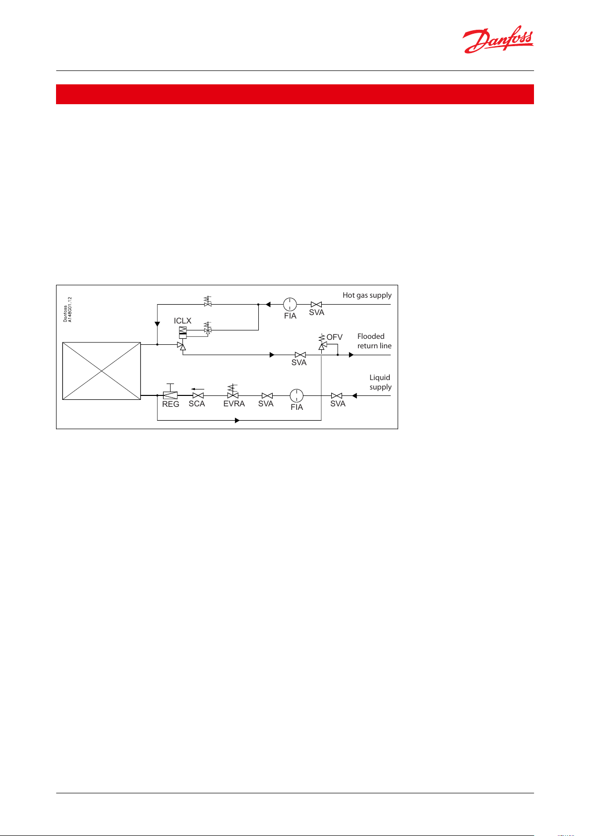
Hot gas supply
Flooded
return line
Liquid
supply
SVA
FIA
OFV
SVA
SVA
FIA
SVAEVRASCA
REG
ICLX
Pressure regulating valve, type OFV and OFV-SS 20-25
Application
Pressure/temperature control during hot gas defrosting
In order to obtain ecient hot gas defrosting the temperature (pressure) must be increased to approx. 10°C (50°F).
The OFV is the optimal solution for controlling the defrosting pressure and thus the corresponding temperature. It is
recommended to start the defrosting cycle by closing the ICLX valve in the liquid supply line and allowing some of
the cold liquid contained in the evaporator to return to the liquid separator.
Close the ICLX valve in the suction line and after a delay open the solenoid valve in the hot gas supply in order to
build up the defrosting pressure in the evaporator. When the defrosting pressure reaches the set OFV-pressure, the
OFV will open and the defrosting pressure will increase to the working pressure ΔP
After defrosting, it is normal practice to open the ICLX in the return line to equalize the pressure to the suction side
before opening to the pump side.
Figure 1: Pressure/temperature control
set
+ ΔP
over
.
© Danfoss | Climate Solutions | 2021.02 AI234986440301en-000601 | 2
Page 3

Pressure regulating valve, type OFV and OFV-SS 20-25
Media
Refrigerants
Applicable to HCFC, HFC, R717(Ammonia) and R744 (CO2).
Flammable hydrocarbons are not recommended. For further information please contact your local Danfoss Sales
Company.
New refrigerants
Danfoss products are continually evaluated for use with new refrigerants depending on market requirements.
When a refrigerant is approved for use by Danfoss, it is added to the relevant portfolio, and the R number of the
refrigerant (e.g. R513A) will be added to the technical data of the code number. Therefore, products for specic
refrigerants are best checked at store.danfoss.com/en/, or by contacting your local Danfoss representative.
© Danfoss | Climate Solutions | 2021.02 AI234986440301en-000601 | 3
Page 4
Description
Values
Temperature range
OFV: -50/+150 °C (-58/+302 °F)
OFV-SS: -60/+150 °C (-76/+302 °F)
Maximum operating pressure
OFV: 40 bar (580 psig)
OFV-SS: 52 bar (754 psig)
Set pressure (Δp)
2 - 8 bar (29 - 116 psi)
Pressure regulating valve, type OFV and OFV-SS 20-25
Product specication
Design
Packing gland OFV
The “full temperature range” packing gland consists of a double O-ring sealing arrangement combined with
permanent lubrication from a grease reservoir. This ensures perfect tightness throughout the whole range: -50/+150
°C (-58/+302 °F).
Flexible O-ring provides perfect sealing over the seat.
Packing gland OFV-SS
The stainless steel packing gland comprises a spring loaded seal packing gland which ensures a perfect tightness in
the range: -60/+150 °C (-76/+302 °F).
The packing glands are equipped with a scraper ring to prevent penetration of dirt and ice into the packing gland.
Installation
The valve is designed to resist very high internal pressure, but as to the pipe system in general, hydraulic pressure
caused by thermal expansions in entrapped refrigerants should be avoided. For further information please see OFV
installation instruction.
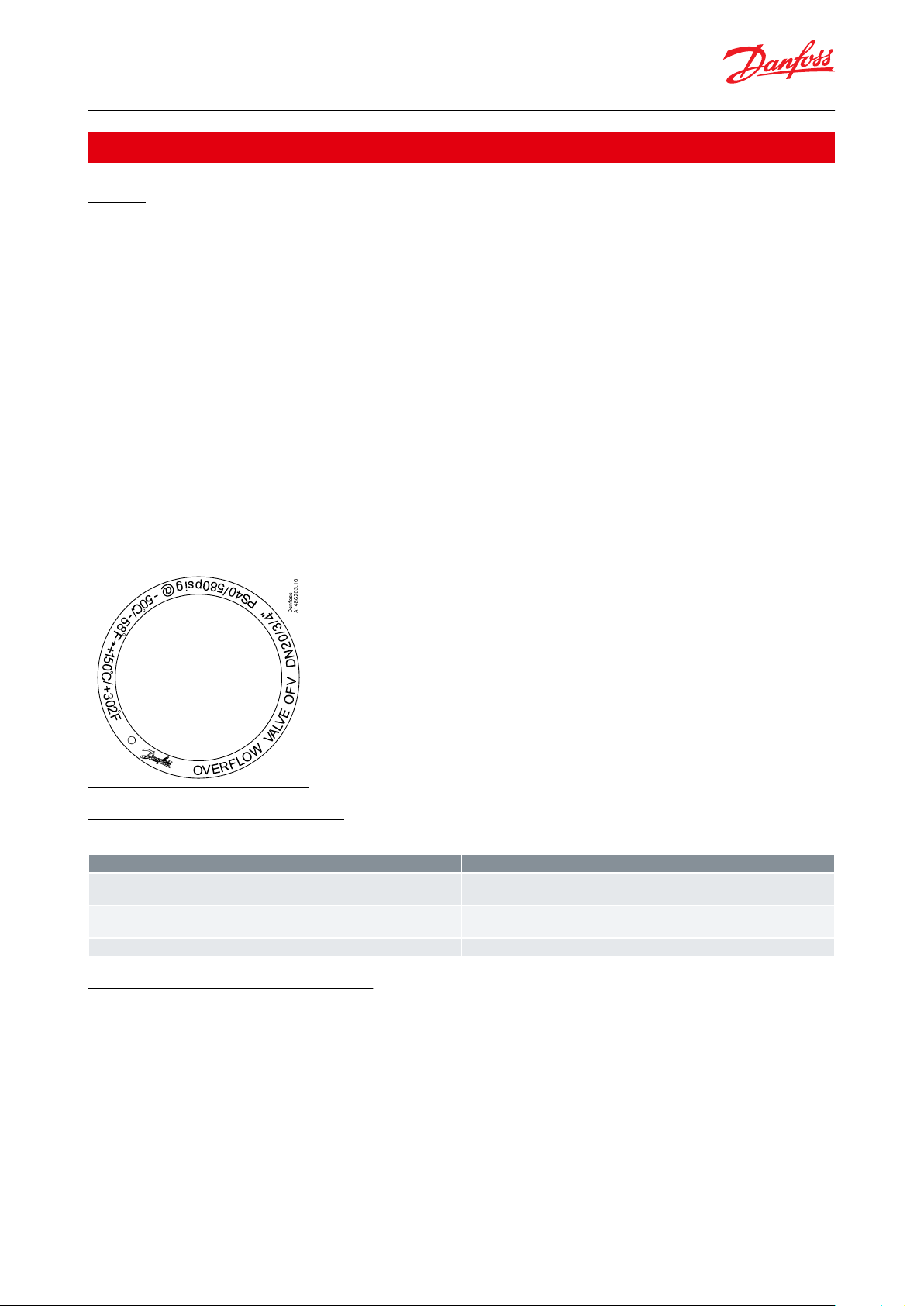
Figure 2: Example of Marking
Ring, Valve type OFV.
Pressure and temperature data
Table 1: Pressure and temperature range
Understanding the OFV in practice
(when working in a defrosting application)
How the OFV works
The opening pressure of the OFV can be adjusted to a specic dierential pressure ΔP
indirectly determines the defrosting pressure.
As illustrated in Figure 3: Pressure and temperature the OFV will work at a pressure somewhat higher than ΔP
namely the ΔP
which will be situated somewhere in the area marked with grey in Figure 3: Pressure and
total
temperature.
© Danfoss | Climate Solutions | 2021.02 AI234986440301en-000601 | 4
by turning the spindle. ΔP
set
set
,
set
Page 5
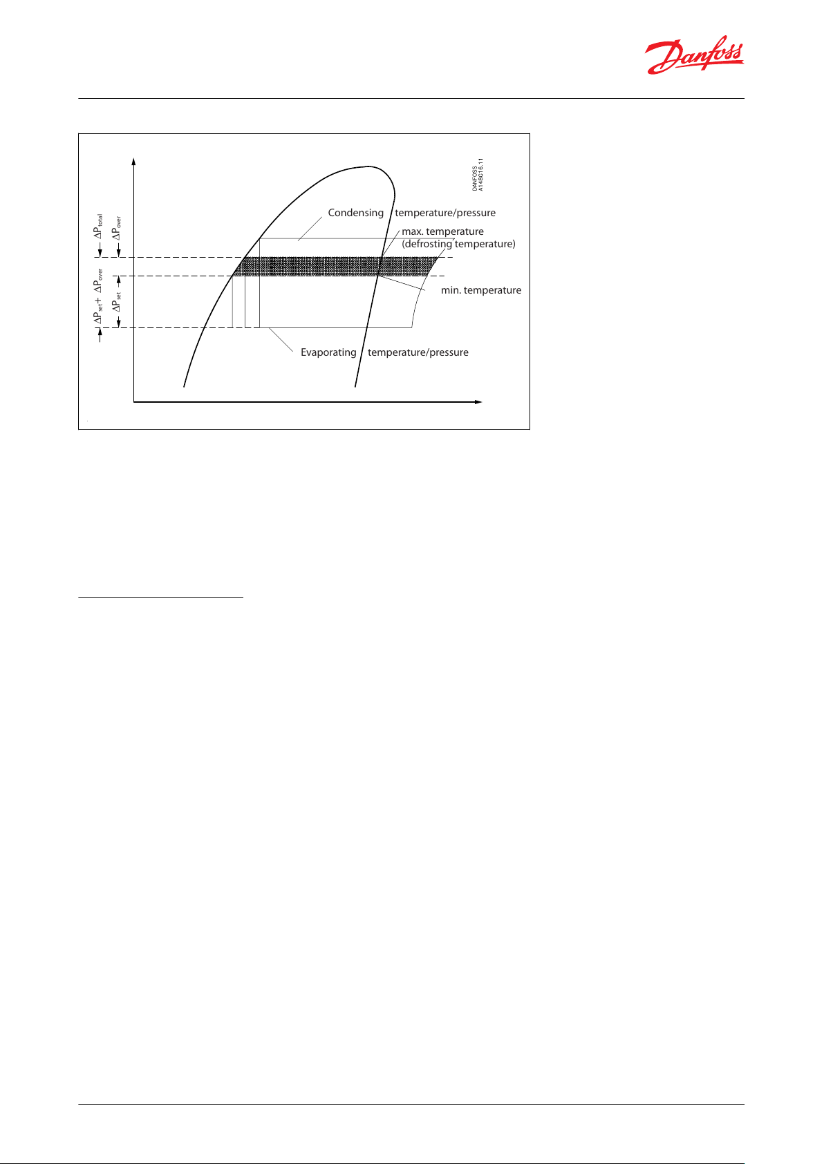
min. temperature
Condensing temperature/pressure
∆P
total
∆P
over
∆P
set
+ ∆P
over
Evaporating temperature/pressure
∆P
set
max. temperature
(defrosting temperature)
Pressure regulating valve, type OFV and OFV-SS 20-25
Figure 3: Pressure and temperature
As ΔP
adjusting the opening dierential pressure ΔP
is plant specic, it follows that the total working pressure (ΔP
over
it is possible to adjust the working pressure ΔP
set
total
= ΔP
set
+ ΔP
) is plant specic too. By
over
set
+ ΔP
over
until you
get the required defrosting pressure.
Defrosting pressure ≈ Evaporating pressure + ΔP
IMPORTANT:
set
+ ΔP
over
.
The OFV valve is back pressure dependent.
Adjusting set pressure
The set pressure is the pressure at which the valve starts to open.
The set pressure is adjustable in the range 2 ‑ 8 bar dierential pressure. When the valve is delivered, a distance
piece is supplied seperately with the valve. The distance piece can be mounted under the spring, thus increasing the
initial tension of the spring. Therefore the valve covers the complete range 2 - 8 bar dierential pressure, as follows:
2 bar - 6.5 bar dierential pressure without distance piece. 3.5 bar - 8 bar dierential pressure with distance piece.
© Danfoss | Climate Solutions | 2021.02 AI234986440301en-000601 | 5
Page 6
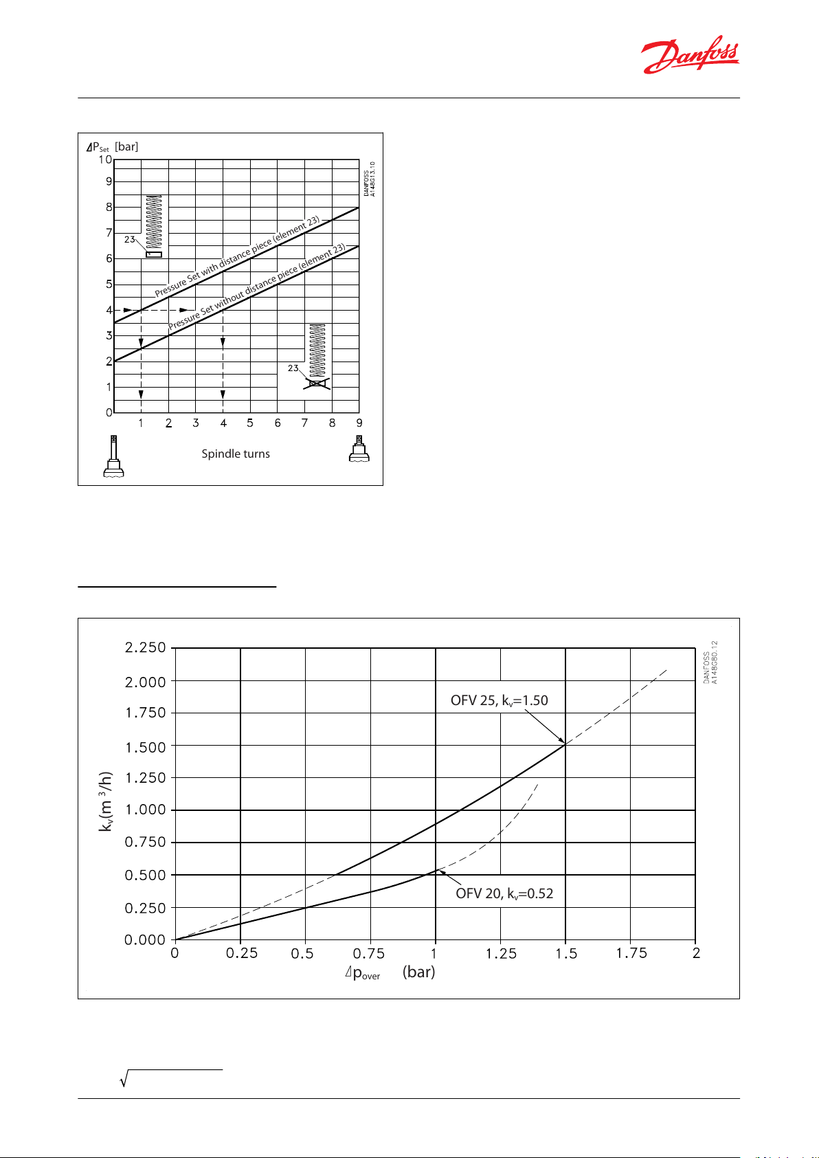
Spindle turns
[bar]P
Set
Pressure Set with distance piece (element 23)
Pressure Set without distance piece (element 23)
p
over
(bar)
k
v
(m
3
/h)
OFV 20, kv=0.52
OFV 25, kv=1.50
Pressure regulating valve, type OFV and OFV-SS 20-25
Figure 4: Adjusting set pressure
Illustrated gure shows set pressure as a function of the spindle turns
NOTE:
See material specication and installation an maintenance instruction for OFV.
Computation and selection
Figure 5: kv values for OFV 20 - 25
The capacity of the OFV valves can be calculated by the following formulas:
Liquids without phase change
r × ΔP
G = k
v
© Danfoss | Climate Solutions | 2021.02 AI234986440301en-000601 | 6
total
× 1000
Page 7

Evaporating temperature
–10°C
–20°C
–30°C
–40°C
–50°C
Defrosting temperature
10°C
Mass ow G
OFV
20 (kg/h)
(ΔP
over
= 1 bar , kv = 0.52 m3/h)
577
661
714
747
768
Mass ow G
OFV
25 (kg/h)
(ΔP
over
= 1.5 bar , kv = 1.5 m3/h)
1666
1906
2059
2156
2216
Evaporating temperature
–10°C
–20°C
–30°C
–40°C
–50°C
Mass
ow G0 (kg/h)
2.780 × Q
0
2.712 × Q
0
2.651 × Q
0
2.595 × Q
0
2.544 × Q
0
Pressure regulating valve, type OFV and OFV-SS 20-25
Liquids with phase change (e.g. pressure control during defrost)
G = kv × 0.78 r × ΔP
total
× 1000
G: mass ow (kg/h)
kv: ow rate (m3/h) (the kv value is dependent on ΔP
, see Figure 5: kv values for OFV 20 - 25).
over
ρ: density, liquid (kg/m3)
ΔP
= dierential pressure (bar)
bar
ΔP
= ΔP
bar
Defrosting pressure ≈ Evaporating pressure + ΔP
set
+ ΔP
over
set
+ ΔP
over
Capacity calculation for defrost pressure regulating
Table 2: Max. mass ow (G
Table 3: OFV 20
Table 4: OFV 25
NOTE:
The calculation is based on formula for "liquids with phase change" in the paragraph "Computation and selection".
) for OFV 20 and OFV 25 with R717
OFV
Table 5: Calculating of refrigerant mass ow G
0
Q0: Capacity of the evaporator (kW)
NOTE:
The calculation is based on pump circulating system (Liquid temperature = Evaporating temperature)
Guide line: Defrost capacity G
~ (2 – 3) × G
OFV
0
Example:
An evaporator in a refrigerant plant has a capacity of Qo = 150 kW and a evaporating temperature of -40 °C.
The defrosting temperature has to be controlled with an OFV valve.
Table 2: G0= 2.595 × Q0 = 389 kg/h
The defrosting capacity in this example is 2.5 × G0.
G
≥ 2.5 × 389 = 972 kg/h.
OFV
OFV 25 is selected (G
OFV 25 max.
= 2156 kg/h (Table 2: Max. mass ow (G
) for OFV 20 and OFV 25 with R717)).
OFV
© Danfoss | Climate Solutions | 2021.02 AI234986440301en-000601 | 7
Page 8
1
24
5
22
21
14
13
20
16
3
2
12
4
9
8
18
17
23
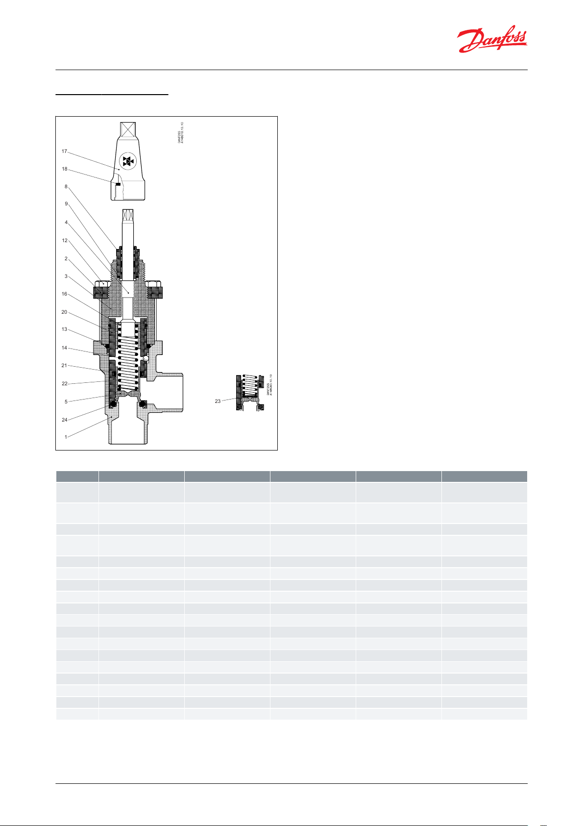
No.
Part
Material
EN
ISO
ASTM
1
Housing
Steel
P285 QH
EN10222-4
LFA350
2
Bonnet, Flange
Steel
P275 NL1
EN10028-3
3
Bonnet, Insert
Steel
4
Spindle
Stainless steel
X10 CrNi S18-9
17440
Type 17
683/13
AISI 303
5
Cone
Steel8Packing gland
Steel9Packing washer
Aluminium
12
Bolts
Stainless steel
A2-70
A2-70
Type 308
13
O-ring
Cloroprene (Neoprene)
14
Spring
Steel16Spring washer
Steel17Cap
Aluminium
18
Gasket for cap
Nylon20Guide piece
Steel21O-ring
Cloroprene (Neoprene)
22
Sealing ring
PTFE (Teon)
23
Distance piece
Steel24O-ring
Cloroprene (Neoprene)
Pressure regulating valve, type OFV and OFV-SS 20-25
Material specication
Figure 6: OFV
Table 6: Material and part list
© Danfoss | Climate Solutions | 2021.02 AI234986440301en-000601 | 8
Page 9

1
24
5
22
21
14
13
20
16
3
2
12
4
9
8
18
17
23
No.
Part
Material
EN
ISO
ASTM
1
Housing
Stainless steel
X5CrNi18-10
EN10088
AISI 304
2
Bonnet, Flange
Stainless steel
X5CrNi18-10
EN10088
AISI 304
3
Bonnet, Insert
Stainless steel
4
Spindle
Stainless steel
X8CrNiS18-9
DIN 17440
Type 17
683/13
AISI 303
5
Cone
Steel
9SMn28
Type 2
12138Packing gland
Stainless steel
9
Packing washer
Non asbestos
12
Bolts
Stainless steel
A2-70
A2-70
Type 308
13
O-ring
Cloroprene (Neoprene)
14
Spring
Steel16Spring washer
Steel
Steel17Spindle seal cap
Aluminium
18
Seal cap gasket
Nylon20Guide piece
Steel21O-ring
Cloroprene (Neoprene)
22
Sealing ring
PTFE (Teon)
23
Distance piece
Steel24O-ring
Cloroprene (Neoprene)
Pressure regulating valve, type OFV and OFV-SS 20-25
Figure 7: OFV-SS 20 - 25 (¾ - 1")
Table 7: Material and part list
© Danfoss | Climate Solutions | 2021.02 AI234986440301en-000601 | 9
Page 10
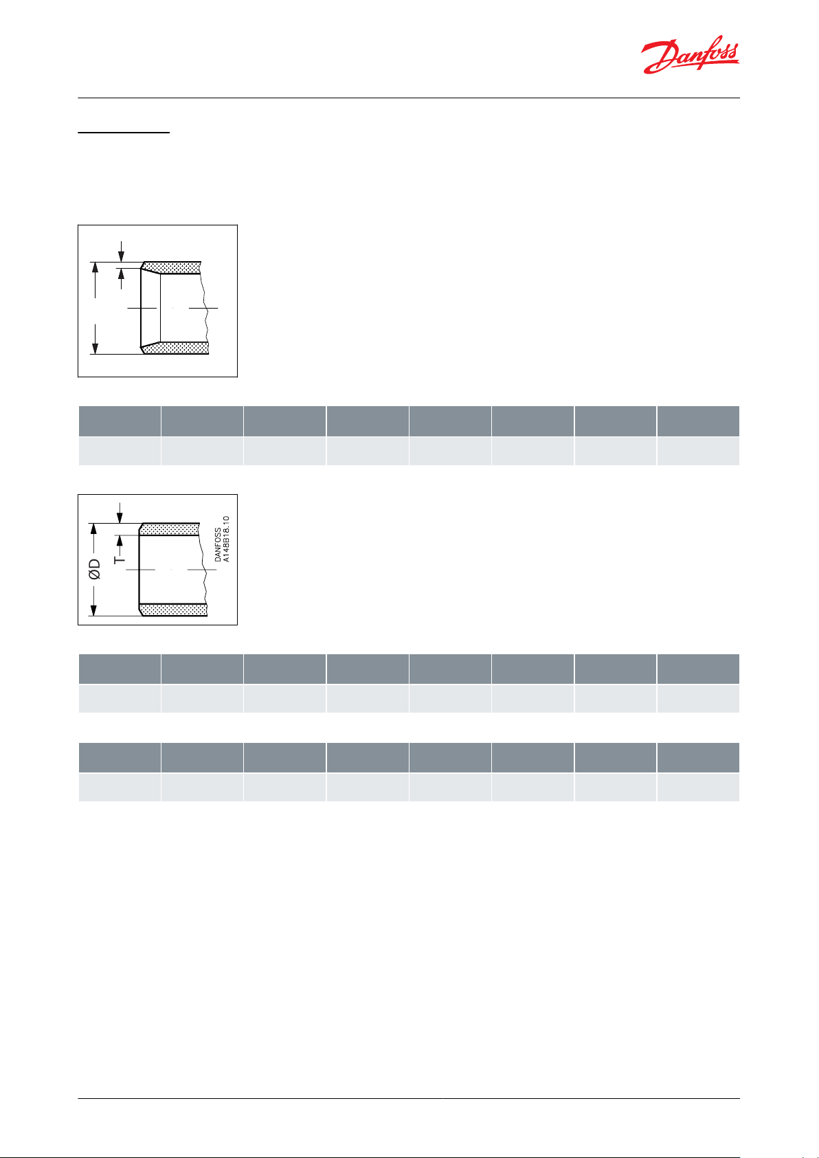
T
ØD
Danfoss
A148B15.10
SizemmSize
in.ODmmTmmODin.Tin.
kv-angle
m3/h
Cv-angle
USgal/min
2025¾126.9
33.7
2.3
2.6
1.06
1.33
0.09
0.10
0 - 0.52
0 - 1.50
0 - 0.60
0 - 1.74
T
ØD
SizemmSize
in.ODmmTmmODin.Tin.
kv-angle
m3/h
Cv-angle
USgal/min
2025¾126.9
33.7
4.0
4.6
1.06
1.33
0.16
0.18
0 - 0.52
0 - 1.50
0 - 0.60
0 - 1.74
SizemmSize
in.ODmmTmmODin.Tin.
kv-angle
m3/h
Cv-angle
USgal/min
2025¾126.9
33.7
2.9
3.5
1.06
1.33
0.11
0.14
0 - 0.52
0 - 1.50
0 - 0.60
0 - 1.74
Pressure regulating valve, type OFV and OFV-SS 20-25
Connections
Available with the following connections:
• Welding DIN (EN 10220)
• Welding ANSI (B 36.19M)
Figure 8: DIN
Table 8: Butt-weld DIN (EN 10220)
Figure 9: ANSI
Table 9: Butt-weld ANSI (B 36.10M)
Table 10: Butt-weld ANSI (B 36.19M, SCHEDULE 40)
© Danfoss | Climate Solutions | 2021.02 AI234986440301en-000601 | 10
Page 11

G
G
C
D
Cmin.
H
Valve size
G
C
C
min
∅DHWeight
OFV 20 (¾
mm
in.451.77
230
9.1
290
11.4381.5602.4
2.0 kg
4.4 lb
OFV 25 (1 in.)
mm
in.451.77
230
9.1
290
11.4381.5602.4
2.0 kg
4.4 lb
Pressure regulating valve, type OFV and OFV-SS 20-25
Dimensions and weights
Figure 10: OFV 20 - 25
Table 11: OFV 20 - 25
NOTE:
Specied weights are approximate values only.
© Danfoss | Climate Solutions | 2021.02 AI234986440301en-000601 | 11
Page 12

Valve type
OFV
OFV-SS
Over Flow Valve in carbon steel
Over Flow Valve in stainless steel
Nominal size in mm
20
25
DN 20
DN 25
Connections
D
A
Butt-weld connection: DIN EN 10220
Butt-weld connection: ANSI B 36.19M
Valve housing
1
Angle ow
Materials
3
Housing: P285 QH, Bonnet: P275 NL1
Other equipment
3
Cap, short spindle with Cloroprene (Neoprene) O-ring
OFV25D13
3
Size
Type
Code No.
mm
in
20
¾
OFV 20 A 133
2412+185
20
¾
OFV 20 D 133
2412+183
20
¾
OFV-SS 20 D ANG OVER FLOW VALVE 52 bar
148G3194
25
1
OFV 25 A 133
2412+186
25
1
OFV 25 D 133
2412+184
25
1
OFV-SS 25 A ANG OVER FLOW VALVE 52 bar
148G3843
25
1
OFV-SS 25 D ANG OVER FLOW VALVE 52 bar
148G3195
Pressure regulating valve, type OFV and OFV-SS 20-25
Ordering
How to order
The table below is used to identify the valve required.
Please note that the type codes only serve to identify the valves, some of which may not form part of the standard
product range.
For further information please contact your local Danfoss Sales Company.
Table 12: Type codes
Table 13: Example for type codes
IMPORTANT:
Where products need to be certied according to specic certication societies or where higher pressures are
required, the relevant information should be included at the time of order.
Table 14: Opening dierential pressure 2 - 8 bar (29 - 116 psi):
© Danfoss | Climate Solutions | 2021.02 AI234986440301en-000601 | 12
Page 13

OFV valves are approved and CE-marked in accordance with the Pressure Equipment Directive - 97/23/EC.
OFV
Nominal bore
DN≤ 25 mm (1 in.)
Classied for
Fluid group I
Category
Article 3, paragraph 3
File name
Document type
Document topic
Approval authority
RU Д-DK.БЛ08.В.00191_18
EAC Declaration
Machinery & Equipment
EAC
033F0691.AE
Manufacturers Declaration
RoHS
Danfoss
033F0686.AH
Manufacturers Declaration
PED
Danfoss
033F0473.AD
Manufacturers Declaration
ATEX
Danfoss
19.10327.266
Marine - Safety Certicate
-
RMRS
Pressure regulating valve, type OFV and OFV-SS 20-25
Certicates, declarations, and approvals
The list contains all certicates, declarations, and approvals for this product type. Individual code number may have
some or all of these approvals, and certain local approvals may not appear on the list.
Some approvals may change over time. You can check the most current status at danfoss.com or contact your local
Danfoss representative if you have any questions.
Table 15: Pressure Equipment Directive (PED)
For further details / restrictions - see Installation Instruction
Table 16: OFV
© Danfoss | Climate Solutions | 2021.02 AI234986440301en-000601 | 13
Page 14

Online support
Danfoss oers a wide range of support along with our products, including digital product information, software,
mobile apps, and expert guidance. See the possibilities below.
The Danfoss Product Store
The Danfoss Product Store is your one-stop shop for everything product related—no matter where
you are in the world or what area of the cooling industry you work in. Get quick access to essential
information like product specs, code numbers, technical documentation, certications, accessories,
and more.
Start browsing at store.danfoss.com.
Find technical documentation
Find the technical documentation you need to get your project up and running. Get direct access to
our ocial collection of data sheets, certicates and declarations, manuals and guides, 3D models
and drawings, case stories, brochures, and much more.
Start searching now at www.danfoss.com/en/service-and-support/documentation.
Danfoss Learning
Danfoss Learning is a free online learning platform. It features courses and materials specically
designed to help engineers, installers, service technicians, and wholesalers better understand the
products, applications, industry topics, and trends that will help you do your job better.
Create your Danfoss Learning account for free at www.danfoss.com/en/service-and-support/learning.
Get local information and support
Local Danfoss websites are the main sources for help and information about our company and
products. Find product availability, get the latest regional news, or connect with a nearby expert—all
in your own language.
Find your local Danfoss website here: www.danfoss.com/en/choose-region.
Spare Parts
Get access to the Danfoss spare parts and service kit catalog right from your smartphone. The app
contains a wide range of components for air conditioning and refrigeration applications, such as
valves, strainers, pressure switches, and sensors.
Download the Spare Parts app for free at www.danfoss.com/en/service-and-support/downloads.
Coolselector®2 - nd the best components for you HVAC/R system
Coolselector®2 makes it easy for engineers, consultants, and designers to nd and order the best
components for refrigeration and air conditioning systems. Run calculations based on your operating
conditions and then choose the best setup for your system design.
Download Coolselector®2 for free at coolselector.danfoss.com.
Danfoss can accept no responsibility for possible errors in catalogues, brochures and other printed material. Danfoss reserves the right to alter its
products without notice. This also applies to products already on order provided that such alterations can be made without subsequential
changes being necessary in specications already agreed. All trademarks in this material are property of the respective companies. Danfoss and
the Danfoss logotype are trademarks of Danfoss A/S. All rights reserved.
© Danfoss | Climate Solutions | 2021.02 AI234986440301en-000601 | 14
 Loading...