

Page 1
Installation guide
020R5421
020R5421
Check and Stop valve
Type OFC
Refrigerant:
For a complete list of approved refrigerants, visit http://store.danfoss.com/ and search for individual code
020R5 421
numbers, where refrigerants are listed as part of product details.
Oil: OFC valve is designed for an oil-free environment
020R5 421
Media Temperature:
Min. 0 ⁰C / 32 ⁰F
Max. 90 ⁰C / 194 ⁰F, short term up to 100⁰C / 212⁰F
Contents of accessory box
• Outlet flange for 3 1/8 in. copper tube
• Outlet flange fasteners
• O-ring for outlet flange
• O-ring lubrication (2 gram)
• Additional check valve springs (2 pcs):
- Yellow spring, for 45⁰ down orientation
- Red spring, for horizontal orientation
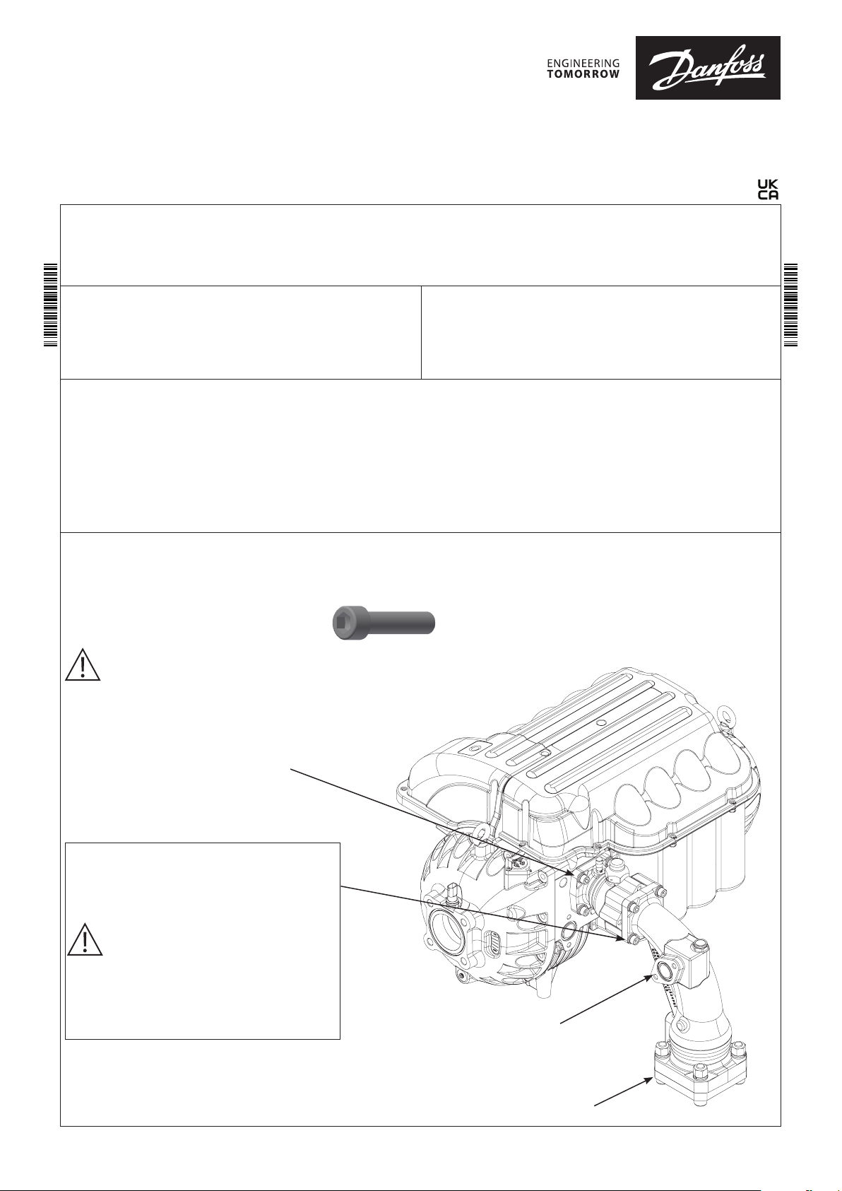
Interface Connections:
Install valve directly on Danfoss Turbocor compressor, picture shown with vertical down installation.
All fasteners and bolts require stainless steel. Bolts with minimum class A2-70.
NOTE: Protection of entire valve including steel
flange is recommended after installation for outdoor use.
Max. Working Pressure:
PS/MWP = 23 bar / 334 psig
Reference specific compressor requirements
Ball valve clocking may be changed by removing
bolts and rotating ball valve housing without
retracting the ball valve assembly away from the
elbow.
NOTE: refer to check valve orientation options
below
Torque: 38 Nm ± 4 Nm
© Danfoss | Climate Solutions | 2021.06 AN371420239255en-000101 | 1
Staging Port:
Bolt size – M10x1.5
Torque: 38 Nm ± 4 Nm
Outlet Flange Fasteners:
Torque - 110 Nm
Info for UK customers only: Danfoss Ltd. Oxford Road, UB9 4LH Denham, UK.
Page 2
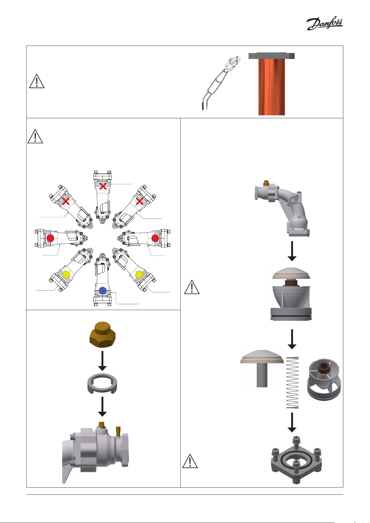
Outlet Flange Brazing:
ng
Place outer flange on evenly cut copper pipe
NOTE: ensure flange is not mounted on main
housing during brazing
Min 5% Ag
Orientation:
NOTE: Check valve spring must be changed when using any
orientation other than vertical downing
Danfoss
Horizontal
Red spring
45° down
Yellow spri
20R01
45° up
Not allowed
Horizontal
Red spring
45° down
Yellow spring
Vertical up
Not allowed
Vertical down
Blue spring
(as delivered)
45° up
Not allowed
When changing check valve spring:
1. Remove check valve insert from main housing
2. Remove check valve head
3. Remove spring and replace with correct color based on intended orientation
4. Replace check valve head and insert
5. Install outlet flange, O-ring and fasteners
Main housing
Check valve insert
NOTE: Use silicone lubricant spray
at O-ring if needed
Always replace lock ring and cap after opening/ closing the
ball valve
Check valve head
Check valve spring
Outlet flange,
O-ring and fasteners
NOTE: Apply provided lubrication to
O-ring
© Danfoss | Climate Solutions | 2021.062 | AN371420239255en-000101
 Loading...