

Page 1
Data sheet
Electronic Oil Burner Control OBC 84.10
Description
Function
The microprocessor based control OBC 84.10
offers stable and precise timings independent of
variations in supply voltage and ambient
temperature.
The control is undervoltage protected in
accordance with EN 298:2012. In case of
The OBC 84.10 controls the cut-in and cut-out of
the oil burner’s components and monitors that
the combustion cycle is performed safely.
When the boiler thermostat (TR) cuts in, heating
of the oil in the oil preheater (OFV) will begin.
Once the release temperature is reached and the
oil preheater’s thermostat (OTR) cuts in, the
burner motor will start the pre-purge and power
will simultaneously be applied to the ignition
(TT). Following the pre-ignition and pre-purge
time, the oil will be released by valve V1 being
opened and subsequently V2 will be opened.
When the boiler thermostat opens after the
heating period power will be cut off and all
relays at the outputs will open and be ready for
the next start-up cycle.
Operating information
OBC 84.10 is equipped with a two-coloured LED
which displays both the operating status and can
indicate the causes of errors leading to lockout.
In the event of operating lockout, the cause of
error can be read out as a flash code by holding
down the reset button for at least 5 seconds and
then releasing it. Undervoltage will, however, be
displayed automatically. Reset can be performed
directly in alarm mode (constant red light) or in
flash code mode by pressing the reset button for
at least 0.5 seconds but no more than 3 seconds.
In flash code mode it is possible to return to
alarm mode by holding down the reset button
again for at least 5 seconds.
undervoltage the control will prevent the burner
from starting and simultaneously show a flash
code. Besides this, up to five other fault types can
be read out as flash codes when the control is in
lockout.
The design complies with the requirements of
the RoHS and WEEE directive.
Application and features
• For 2 stage burners above 30 kg/h and WLE
• For burners with or without preheater
• Precise and reproducible timings
• Limitation at 1 restart by flame failure within
the same operating period
• Limitation of 10 min. on preheating time
• Remote reset and alarm output
• Indication of reason for lockout
• Indication of preheating and operation
Normal operation
When the boiler thermostat (TR) cuts in, the reset
button flashes green. As soon as the preheater
thermostat (OTR) cuts in, the reset button lights
up constant green. When the boiler thermostat
cuts out, the green light turns off.
Errors during operation (flash codes):
• If the mains voltage falls below 185 V before
start-up, the control will be blocked from
starting. If the mains voltage falls below 170
V during operation, the oil supply and burner
will be stopped. In both cases, the reset
button will automatically flash 8 times.
When the mains voltages reaches 185 V, the
control will restart as normal. Please note
that the control cannot be reset if the mains
voltage is below 170 V.
• If the mains voltage exceeds 264 V, the control
will automatically enter alarm mode.
The purpose of the overvoltage cut out is
not simply to protect the electronics in the
control, but also the other components in
the burner.
• If light is registered in the final stage of the
pre-purge time, the control will not release
oil and will enter alarm mode.
• If no flame is established at the start, i.e. by
the end of the safety time, the control will
enter alarm mode.
© Danfoss | 2019.09
VD.HN.A3.02 | 1
Page 2
Data sheet Electronic Oil Burner Control OBC 84.10
• In the event of a flame failure during
operation, the oil supply will be cut off after
no more than 1 second and the control will
restart the burner. If flame failure occurs more
than one time in the same operating period
(TR connected), the control will enter alarm
mode.
• If the release temperature in the preheater is
not reached within 10 minutes, the control
will enter alarm mode.
The OBC 84.10 processor also monitor the
outputsat TT, V1 and V2. If errors like electrical
noise (EMC) are registered at the outputs, the
control will enter alarm mode.
Note:
OBC 84.10 can only be reset whi le the supply voltage is connec ted.
Flash codes
Event Code
False light 2 flashes
No flame when safety time elapses 3 flashes
More than three restar ts in the same
cycle
Max. waiting time on preheater overrun
(10 mi n)
Supply voltage above 264 V a.c. 6 flashes
Undervoltage <170 V (automatic) 8 flashes
Application failure (EMC)
4 flashes
5 flashes
constant
flashes
2 | © Danfoss | 2019.09
VD.HN.A3.02
Page 3

Data sheet Electronic Oil Burner Control OBC 84.10
Technical Data
Symbols
Boiler thermostat
High temperature cutout
Ignition unit
Burner motor
Solenoid valve
Photo unit or UV sensor
External alarm
L Phase wire
N Neutral wire
Oil preheater ⁄ Oil preheater thermostat
Hold relay
** Remote reset
* Due to the initia lisation of the electroni cs it may take up to two secon ds before ignition is enabl ed
** If the remote res et is activated more than 4 times w ithin 15 minutes it is ignore d and cannot be used before the 15 minutes ha s elapsed
unless the powe r to the control box is turned of f or if the reset is done on the contro l box itself.
Rated voltage 230 V~
Operating range 195-253 V~
Frequency 50-60 Hz ± 6%
Consumption 6 VA
Reset Immediately
Reaction time on flame failure Max. 1 s
Undervoltage protection < 170 V
Protection class II
Pollution degree 2
Main fuse (terminal load, see electrial diagram) Max. 10 A
Cable connection Plate for 5 PG 11 screwed connections or plate with knockouts
Ambient temperature -20 to +60°C
Installation Any position
Enclosure IP40
Flame monitoring UV, LD or LDS
Required flame signal
Max. cable length between OBC and UV, LD/LDS 20 m (installed separately)
No flame / dark ≤5 A
Flame / light ≥65 A
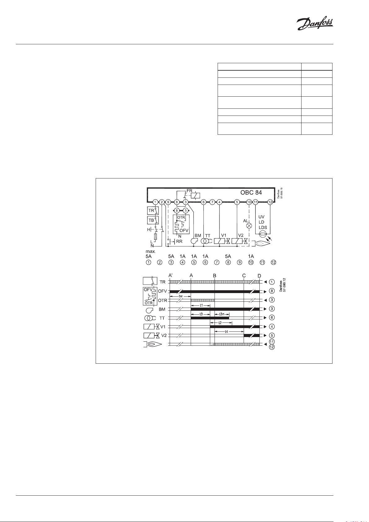
Time function/explanation
Output signals of control
Required input signals
A’ Initiation of burners with oil preheater OFV
A Initiation of burners without oil preheater
B Flame formation
C Operation position
D Burner stop
tw Heating of oil preheater until OTR switches on
t1 Pre-purge 25 s
t2 Safety time 5 s
t3* Pre-ignition 25 s
t4 Inter val V1-V2 5 s
t3n Post-ignition 2 s
Ordering
VD.HN.A3.02
Description Weight Code no.
OB C 84.10 200 g 057H8705
Base BHB 70 g 057H7010
Front plate for BHB, 5 × PG 11 12 g 05 7H7 011
Front plate for BHB, 8 × knockouts 12 g 057H7012
© Danfoss | 2019.09 | 3
Page 4

Data sheet Electronic Oil Burner Control OBC 84.10
Dimensions
Additional documentation on burner components is available on http://heating.danfoss.com/ or
https://store.danfoss.com/
4 | © Danfoss | DHS-SDBT/DK | 2019.09
VD.HN.A3.02
 Loading...