

Page 1
Design Guide
VACON® NXP DCGuard™
Page 2

Page 3

Design Guide | VACON® NXP DCGuard™
Contents
Contents
1 Introduction 5
1.1 Purpose of this Design Guide 5
1.2 Additional Resources 5
1.3 Manual Version 5
1.4 Type Approvals and Certifications 5
2 Safety 6
2.1 Safety Instructions 6
3 Product Overview 7
3.1 DC Grids and Selectivity 7
3.2 Selectivity with Fuses 7
3.3 Application Functionality 8
3.4 Protection Functions 9
3.4.1 Instant Current Cut-Off 9
3.4.2 Rapid Current Cut-Off 10
3.4.3 High Current Cut-Off 10
3.4.4 Overload Detection 10
3.5 Controlled Voltage Ramp-Up 10
3.5.1 Controlled Voltage Ramp-Up of a Loaded System 10
3.5.2 Controlled Voltage Ramp-Up into a Short Circuit 10
3.6 System Control Principle 10
3.7 Application Requirements 11
3.8 System Integrator Responsibilities 11
3.9 System Selectivity 12
4 Component Overview 14
4.1 Fuses 14
4.2 Filters 15
4.2.1 Calculating the Filter Impedance 15
4.3 Mechanical Disconnectors 16
4.3.1 Closing the Mechanical Disconnectors 17
4.3.2 Opening the Mechanical Disconnectors 18
5 Specifications 19
5.1 Technical Data 19
5.2 Nameplate 20
5.3 Voltage and Current Rating Guidelines 20
5.4 Operation Temperature Range 21
5.5 Power Ratings 21
AJ284746616204en-000101 / DPD02135 | 3Danfoss A/S © 2018.12
Page 4

Design Guide | VACON® NXP DCGuard™
5.5.1 Air-Cooled 500 V Units 21
5.5.2 Air-Cooled 690 V Units 22
5.5.3 Liquid-Cooled 500 V Units 23
5.5.4 Liquid-Cooled 690 V Units 24
5.6 Total Capacitance, Inductance, and Resistance 25
Contents
6 Electrical Installation Guidelines 26
6.1 DCGuard Topologies 26
6.1.1 Directional Topology 26
6.1.2 Peer-to-peer Topology 26
6.1.3 Ring Topology 27
6.2 Parallel Installation 28
6.3 Bus-Tie Cables 28
6.4 HF Capacitors 29
6.5 Cabling 29
6.5.1 Wiring Diagrams for Air-Cooled Inverter Units 30
6.5.2 Wiring Diagrams for Liquid-Cooled Inverter Units 32
6.6 Terminal Definitions 36
6.6.1 Terminal Locations in Air-Cooled Inverter Units 36
6.6.2 Terminal Locations in Liquid-Cooled Inverter Units 39
6.7 Control I/O Configuration 42
7 How to Select the VACON® NXP DCGuard™ 44
7.1 VACON® Select Web Tool 44
AJ284746616204en-000101 / DPD021354 | Danfoss A/S © 2018.12
Page 5

Design Guide | VACON® NXP DCGuard™
Introduction
1 Introduction
1.1 Purpose of this Design Guide
This design guide is intended for qualified personnel, such as:
• Project and systems engineers.
• Design consultants.
• Application and product specialists.
The design guide provides technical information to understand the capabilities of VACON® NXP DCGuard™ for integration into DC
supply systems. Its purpose is to provide design considerations and planning data for integration of the device into a system. It caters
for the selection of the drive units and options for the application in a diversity of installations. Reviewing the detailed product
information in the design stage enables developing a well-conceived system with optimal functionality and efficiency.
1.2 Additional Resources
Other resources are available to understand installation, programming, operation, and options.
• The VACON® NXP DCGuard™ operating guide provides information about the installation and operation of the VACON® NXP
DCGuard™ application.
• The VACON® NXP DCGuard™ application guide provides greater detail on how to work with the application software and how to
set the parameters of the AC drive modules.
• VACON® NXP Common DC Bus and VACON® NXP Liquid-cooled Common DC Bus user manuals provide detailed information for the
installation, commissioning, and operation of the AC drive modules.
• The operating and installation guides for VACON® options give detailed information about specific drive options.
Supplementary publications and manuals are available from Danfoss. See www.danfoss.com for listings.
1.3 Manual Version
This manual is regularly reviewed and updated. All suggestions for improvement are welcome.
The original language of this manual is English.
Table 1: VACON® NXP DCGuard™ Design Guide Version
Version Release date Remarks
A 04.12.2018 First release
1.4 Type Approvals and Certifications
VACON® NXP DCGuard™ is type approved as a circuit breaker/DC-bus tie breaker. For a list of the approvals and certifications, see the
VACON® NXP DCGuard™ product page at www.danfoss.com.
NOTI CE
VACON® NXP DCGuard™ acts as a protection device in a DC power distribution system. Separate approvals as a DC-bus tie
breaker can be required.
Danfoss A/S © 2018.12
AJ284746616204en-000101 / DPD02135 | 5
Page 6

Design Guide | VACON® NXP DCGuard™
Safety
2 Safety
2.1 Safety Instructions
A safety guide is included in the product delivery. Read the safety instructions carefully before starting to work in any way with the
system or its components.
The warnings and cautions in the safety guide give important information on how to prevent injury and damage to the equipment or
the system. Read the warnings and cautions carefully and obey their instructions.
The product manuals with applicable safety, warning, and caution information can be downloaded from https://www.danfoss.com/en/
service-and-support/.
6 | Danfoss A/S © 2018.12
AJ284746616204en-000101 / DPD02135
Page 7

Design Guide | VACON® NXP DCGuard™
Product Overview
3 Product Overview
3.1 DC Grids and Selectivity
Utilizing DC grids rather than AC grids enables power distribution with lower power losses. However, there are few or no international
standards for building a DC grid, especially in marine applications. Short circuit handling is a challenge in DC grids and it is difficult to
ensure the required system functionality by using fuses. Ensuring selectivity and limited short circuit energy requires more
sophisticated protection devices.
Ensuring selectivity in a common-DC system is a challenge, and it becomes even more challenging when there are several inverters
connected to the same DC bus. In a short circuit in the DC bus, the protection fuses burn, but often so do the fuses feeding other vital
equipment in the same system. Even fuses which are not connected directly (nearest) to the short circuit can burn, for example, the
fuses feeding inverters in another place in the same DC bus.
During the first 100–200 μs after a short circuit occurs, the capacitors inside each inverter will supply current to the fault. Since
capacitors can feed out current extremely fast, selectivity is difficult to achieve by only using fuses. One way to improve the total
selectivity in a common-DC-bus system is to split the system in two separate DC grids by using a fast-current cutter/DC-bus tie device.
Danfoss Drives has developed a new fast-current cutter/DC-bus tie device, the VACON® NXP DCGuard™. The semiconductor protection
device is based on standard VACON® NXP inverter hardware and new software. During a short circuit, the VACON® NXP DCGuard™
disconnects the healthy side from the faulty side in microseconds, before the short circuit affects the healthy side. The fast isolation
ensures that the healthy side can continue to operate as normal, also after the short circuit situation. The DCGuard cannot influence
what happens inside the faulty DC grid during a short circuit situation.
3.2 Selectivity with Fuses
In some demanding applications (for example, marine applications) there is a requirement that a single fault must not shut down the
complete system. Because of this requirement, it is required to build the system so that it can withstand a fault without having a total
blackout.
Maintaining the required DC voltage on the healthy side of the DC grid during a fault is one of the main challenges when using fuses to
disconnect the healthy part of the DC grid from the faulty part in a short circuit situation. When a short circuit happens, the voltage on
the faulty side is close to 0 V. Because of the low resistance inside the fuses, also the voltage on the healthy side decreases. It takes time
for the fuses to clear the fault, so there is a significant risk that also the voltage on the healthy side decreases below the undervoltage
trip limit for the inverters in the healthy side. The result is a total blackout.
illustration 1 shows the DC voltage in grids 1 and 2, and the DC current through the fuses when there is a fault in DC grid 2.
Danfoss A/S © 2018.12
AJ284746616204en-000101 / DPD02135 | 7
Page 8
DC Voltage
DC Current
Short
circuit
Fuses
clearance
Short
circuit
Fuses
clearance
Time
Time
Short
circuit
Fuses
clearance
Time
Undervoltage trip
Overvoltage trip
DC Voltage
Undervoltage trip
Overvoltage trip
DC+
DC-
DC+
DC-
DC grid 1
AFE
INU
=
~
=
~
=
~
M
M
G
INU
DC grid 2
e30bg933.10
AFE
INU
=
~
=
~
=
~
M
M
G
INU
Design Guide | VACON® NXP DCGuard™
Product Overview
Illustration 1: Example of Selectivity with Fuses in a Fault Situation
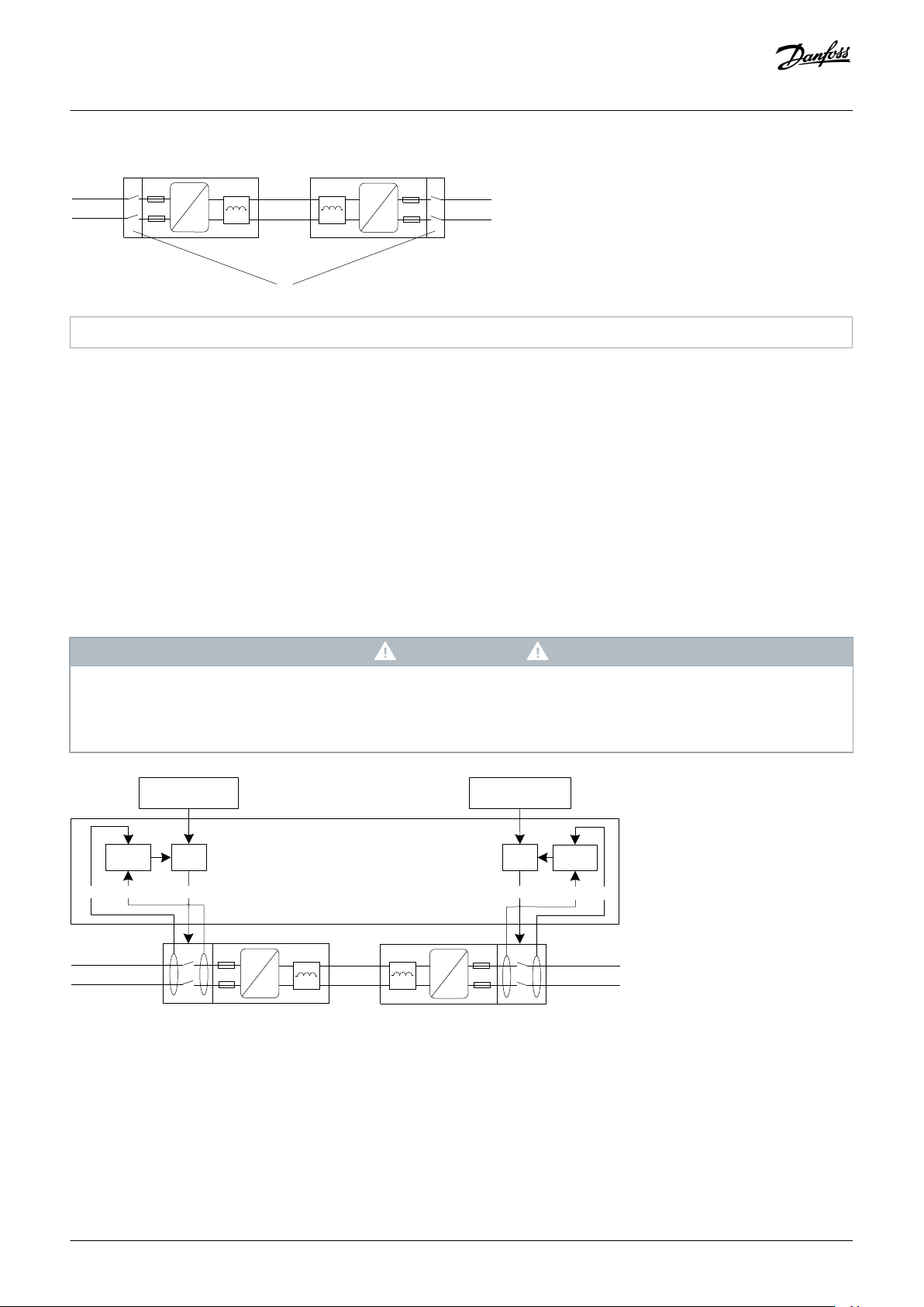
3.3 Application Functionality
VACON® NXP DCGuard™ is a fast DC current cutter device that detects and cuts off an outgoing short-circuit current. The main
function is to isolate the faulty DC grid from the healthy DC grid, before that fault affects the healthy DC grid.
Two inverter units in a DCGuard peer-to-peer topology are required to be able to cut off short-circuit current both ways.
VACON® NXP DCGuard™ consist of VACON® NXP inverter units and application software ADFIF102. To ensure the correct functionality
and safety level, always use the following components together with the DCGuard in a peer-to-peer system:
• An upstream mechanical disconnector if safe disconnection is required.
• Type aR supply fuses in each DC supply line (see the VACON® NXP DCGuard™ design guide for instructions).
• A dU/dt filter (a standard VACON® dU/dt filter can be used).
8 | Danfoss A/S © 2018.12
AJ284746616204en-000101 / DPD02135
Page 9
W
V
DC+
DCGuard 1 DCGuard 2
DC-
DC+
DC-
DC+
DC-
U
V
DC grid 1
AFE
INU
=
~
=
=
=
=
=
~
=
~
M
M
G
INU
DC grid 2
e30bg860.12
AFE
INU
=
~
=
~
=
~
M
M
G
INU
Over load detection
Short-circuit protection
Operational area
Current
Time
Nom. current
Instant trip
Instant current cut-off
Rapid current cut-off
High current cut-off
Bus tie cables over load protection
e30bg894.10
Design Guide | VACON® NXP DCGuard™
Illustration 2: VACON® NXP DCGuard™ Peer-to-Peer Topology
Product Overview
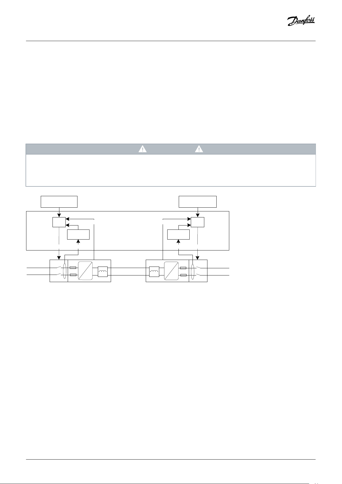
3.4 Protection Functions
The VACON® NXP DCGuard™ application has different short-circuit protection levels. The levels can be used to ensure correct system
selectivity. The instant current cut-off is non-programmable, but the other functions can be programmed. The protection functions
also have separate programmable responses.
Illustration 3: VACON® NXP DCGuard™ Safety Layers
3.4.1 Instant Current Cut-Off
• Non-programmable short-circuit current cut-off.
VACON® NXP DCGuard™ trips within μs to fault F1 in a low impedance short circuit.
•
• The functionality is handled by the VACON® NXP inverter hardware.
Danfoss A/S © 2018.12
AJ284746616204en-000101 / DPD02135 | 9
Page 10

Design Guide | VACON® NXP DCGuard™
Product Overview
3.4.2 Rapid Current Cut-Off
• Programmable short-circuit current cut-off.
• VACON® NXP DCGuard™ trips within 10–100 μs to fault F63, F64, or F65 in a low to medium impedance short circuit.
• This functionality is handled by the system software and requires enough inductance in the output filter. If there is a short circuit in
the bus-tie cables, a standard dU/dt filter does not have enough inductance to ensure an exact tripping level.
• For details about programming this function, see the VACON® NXP DCGuard™ Application Guide.
3.4.3 High Current Cut-Off
• Programmable high circuit current cut-off.
• VACON® NXP DCGuard™ trips within 100 ms to fault F86, F87, or F88 if the current is too high for a too long time.
• This functionality is handled by the VACON® NXP DCGuard™ application software.
• For details about programming this function, see the VACON® NXP DCGuard™ Application Guide.
3.4.4 Overload Detection
• Programmable overload detection.
• VACON® NXP DCGuard™ trips within 100 ms to fault F83, F84, or F85 in an overload situation in the DC cables out from the
DCGuard.
• This functionality is handled by the VACON® NXP DCGuard™ application software.
• For details about programming this function, see the VACON® NXP DCGuard™ Application Guide.
3.5 Controlled Voltage Ramp-Up
To prevent a high inrush current when a VACON® NXP DCGuard™ is connecting to the bus-tie cables, a controlled voltage ramp up of
the bus-tie cable voltage is always performed before closing the DCGuard. The voltage is ramped up from the current level to full DC
voltage. Typically, the voltage rise time from 0 V to full DC voltage is 200–400 ms. The voltage rise time and switching frequency are
programmable.
3.5.1 Controlled Voltage Ramp-Up of a Loaded System
VACON® NXP DCGuard™ can perform a controlled voltage ramp-up of a loaded system, but the voltage rise time must be adjusted
case by case. The maximum current must stay below the tripping limit for the VACON® NXP DCGuard™ units during the controlled
voltage ramp-up.
3.5.2 Controlled Voltage Ramp-Up into a Short Circuit
If a controlled voltage ramp-up is performed to a system where a short circuit is present, the VACON® NXP DCGuard™ detects the short
circuit and trips.
3.6 System Control Principle
VACON® NXP DCGuard™ is only one component in a complete system, which often includes different layers of controls with different
responsibilities.
10 | Danfoss A/S © 2018.12
AJ284746616204en-000101 / DPD02135
Page 11
Energy Management System (EMS)
Power Management System (PMS)
Battery Management
System
Battery
Power Conversion System
Power Conversion Control
(PCC)
Power Conversion
Hardware
Storage System
e30bg936.10
Design Guide | VACON® NXP DCGuard™
• The Energy Management System (EMS) optimizes the energy efficiency of the system. The optimization can include selecting and
prioritizing the use of different energy sources. Normal time scales are from tens of seconds to hours.
• The Power Management System (PMS) includes controlling the power balance in a system which has multiple energy/power
sources. Normal time scales are from grid cycle (20 ms/50 Hz) to seconds.
• The Power Conversion System (PCS) is the system relevant to the VACON® NXP DCGuard™. The PCS includes Power Conversion
Control (PCC) and Power Conversion Hardware (PCH), which is the VACON® NXP hardware. The PCS controls the power conversion
between the energy storage and the system. Normal time scales are from micro seconds to grid cycles.
• The Storage System (SS) includes the Battery Management System (BMS) and the battery. The BMS monitors the storage system
and the storage cell level phenomena.
Product Overview
Illustration 4: Typical Layers in a Control System
3.7 Application Requirements
The VACON® NXP DCGuard™ application requires:
• NXP3 control board VB761 revision D or newer.
• System software version NXP00002V193 or newer.
3.8 System Integrator Responsibilities
The VACON® NXP DCGuard™ is developed to be used as a component in a common-DC system. System design and control must be
done by the system integrator.
The VACON® NXP DCGuard™ peer-to-peer system is made of two independent DCGuard units, although they operate as a pair. It is the
responsibility of the system integrator to implement the two DCGuard units in to the system, to ensure correct functionality, and to
ensure correct safety level.
Especially consider the following when designing the system:
Danfoss A/S © 2018.12
AJ284746616204en-000101 / DPD02135 | 11
Page 12
e30bg934.10
Design Guide | VACON® NXP DCGuard™
Product Overview
• A fault in one of the two DCGuard units must lead to the opening of the other DCGuard unit.
• To ensure safe disconnection of the VACON® NXP DCGuard™ and the bus-tie cables, a mechanical disconnector is required in front
of each DCGuard.
• The mechanical disconnector in front of each DCGuard unit must only be closed when the voltage level on both sides of the
mechanical disconnector is within the limits of the mechanical disconnectors closing capacity. Meaning that the inrush current is
within the mechanical disconnectors closing capacity.
• The mechanical disconnector in front of each DCGuard unit must only be opened when the conducted current is less than the
maximum breaking capability of the mechanical disconnector.
• Closing a DCGuard unit must only be possible when the other side of the system is ready to be powered up.
• VACON® NXP liquid-cooled inverters do not control or monitor the cooling liquid flow through their own cooling elements. The
system integrator must therefore take responsibility of implementing sufficient control and monitoring of the cooling liquid circuit.
• If the active control place for the DCGuard unit is keypad, make sure that there is a possibility to stop the DCGuard also in case the
keypad is removed from the drive. In case the parameter Keypad/PC fault mode (ID 1329) is set to 0/No response or 1/Warning, it
must be ensured on system level that there is the possibility for local control. This can be done, for example, by forcing to I/O or
fieldbus control by a digital input.
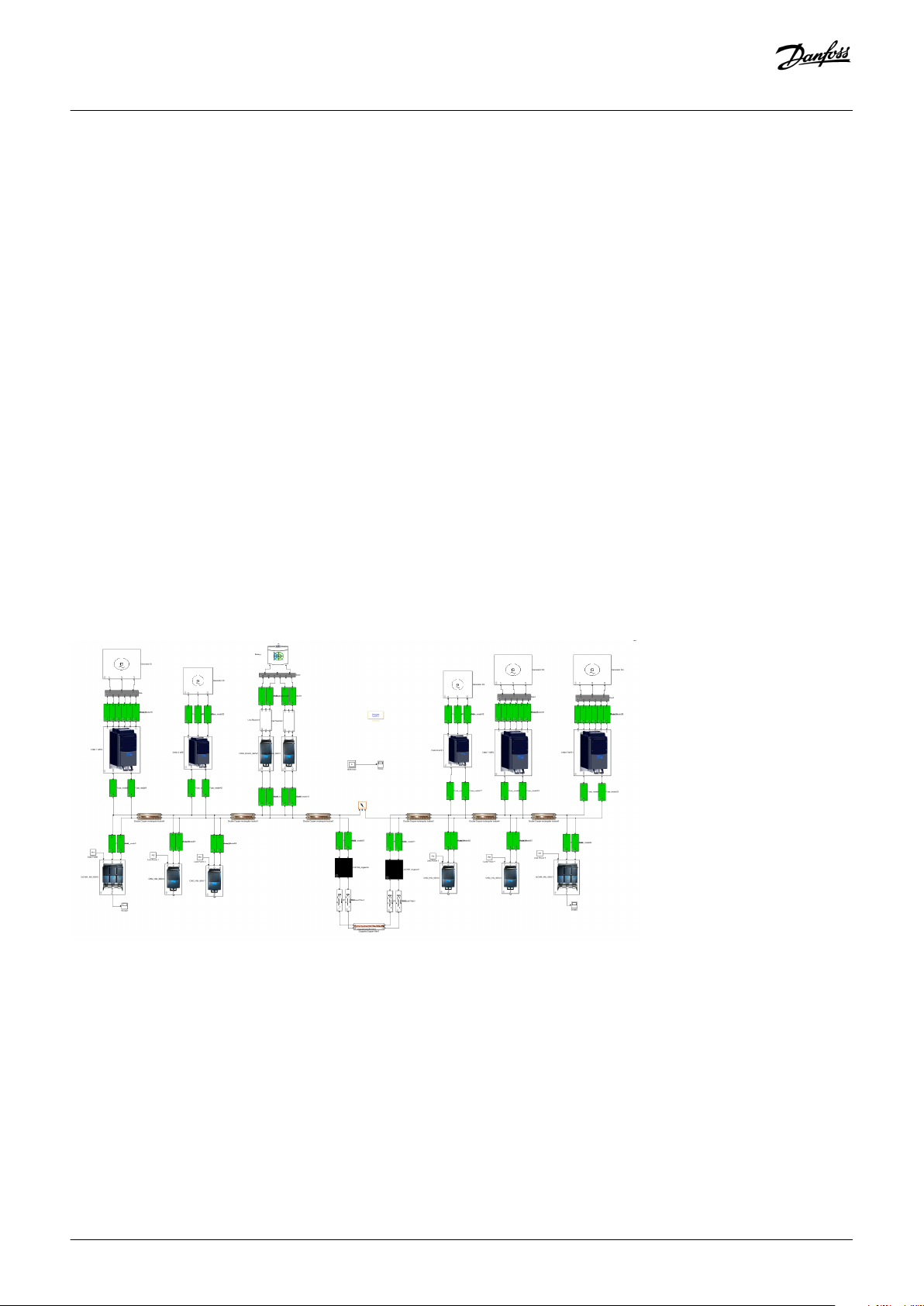
3.9 System Selectivity
VACON® NXP DCGuard™ has received several Type approval certificates, but often the approval societies require an approval of the
whole system. To get such a system approval, a selectivity study of the faulty side is required.
MATLAB®/Simulink® can be used to simulate what happens inside the faulty side of the DC grid during a short circuit. Contact the
nearest Danfoss Drives representative for more information.
Illustration 5: Model of a Complete DC-Supply System
12 | Danfoss A/S © 2018.12
AJ284746616204en-000101 / DPD02135
Page 13
e30bg935.10
Design Guide | VACON® NXP DCGuard™
Product Overview
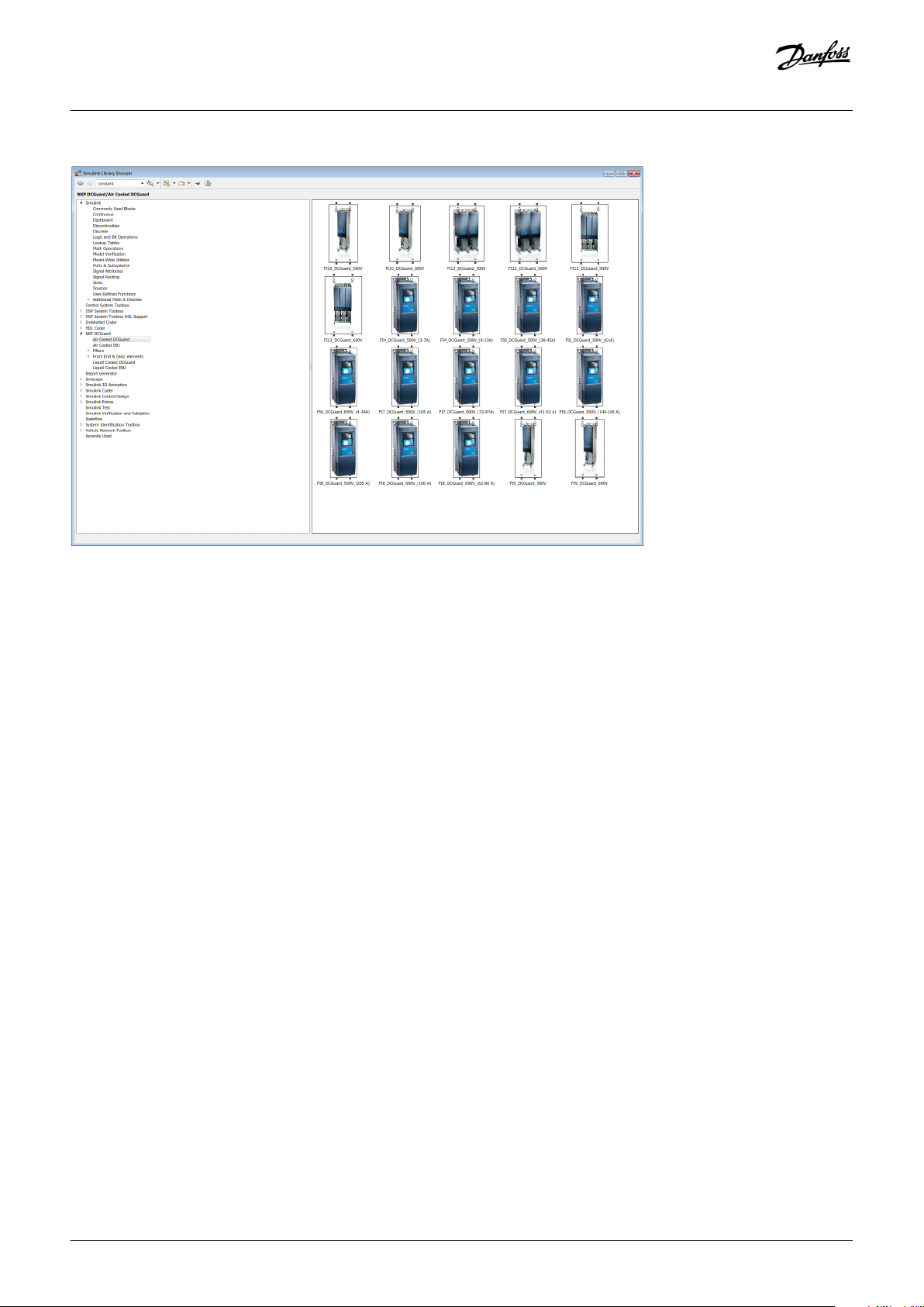
Illustration 6: VACON® NXP DCGuard™ Library in Simulink
®
Danfoss A/S © 2018.12
AJ284746616204en-000101 / DPD02135 | 13
Page 14
B
A
C
D
E
F
e30bg937.10
t
A
B
C
D
E
F
G
e30bg938.10
Design Guide | VACON® NXP DCGuard™
Component Overview
4 Component Overview
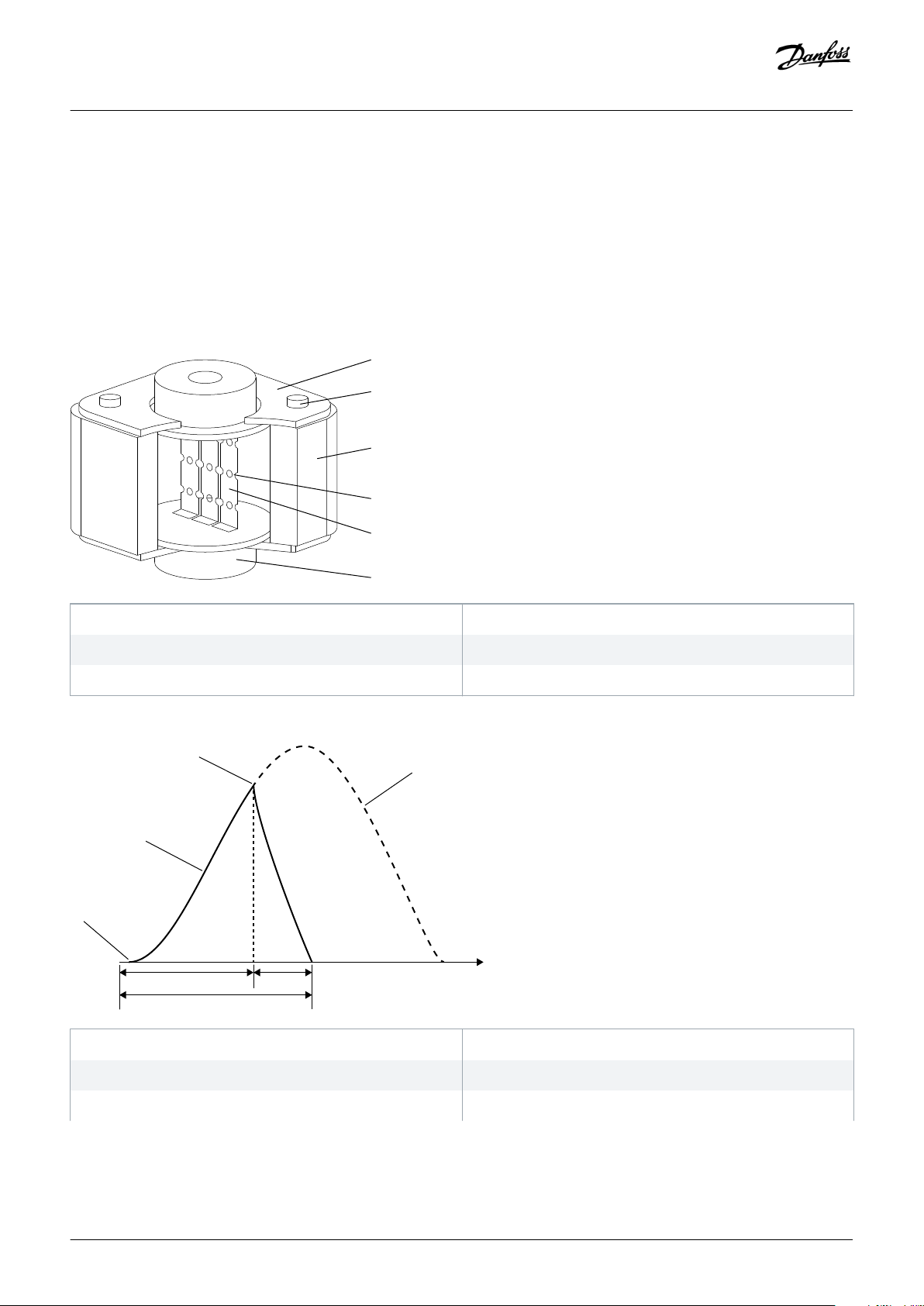
4.1 Fuses
Always protect the VACON® NXP DCGuard™ with aR-type fuses in each DC-supply line.
If there is a short circuit inside the VACON® NXP DCGuard™ unit, the aR-type fuses in each DC-supply line disconnect the unit from the
feeding DC grid. The fuses are back-up fuses for semiconductor protection and only give protection against the effects of short circuit
current. The fuses do not give any overload protection.
A End plate
C Ceramic body
E Element
Illustration 7: Structure of a Type aR Fuse
A Start of fault
C Peak fault current reached at start of arcing
E Pre-arcing time
B Screw
D Reduced sections of element ("weak spots")
F End fitting
B Actual current
D Possible unrestricted fault current
F Arcing time
14 | Danfoss A/S © 2018.12
AJ284746616204en-000101 / DPD02135
Page 15
W
V
DC+
DCGuard 1
DCGuard 2
DC-
DC+
DC-
DC+
DC-
U
V
=
=
=
=
e30bg939.10
L
Design Guide | VACON® NXP DCGuard™
Component Overview
G Total clearing time
Illustration 8: Fuse Functionality in a Fault Situation
See the VACON® NXP user manuals for instructions for the fuse selection. The fuses are not included in the VACON® NXP DCGuard™
delivery.
CA UT IO N
INCORRECT FUSE CONFIGURATION
In certain cases, the correct fuse configuration can differ from the default configuration given in the VACON® NXP user manual!
To find the correct fuse configuration, do a system calculation.
-
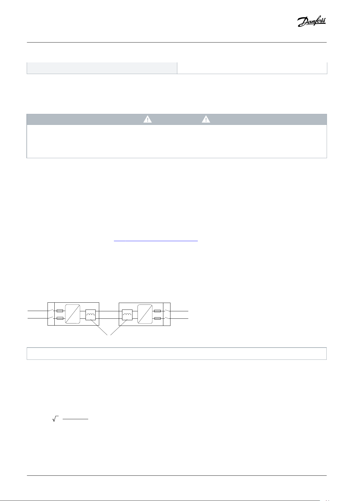
4.2 Filters
VACON® NXP DCGuard™ requires a dI/dt filter in each of the connected output phases (U, V, W).
The purpose for the inductance is to limit the current rise time, so that the programmable protection functionality of the VACON® NXP
DCGuard™ can detect the short circuit and cut the current. If there is a short circuit in the terminals, the dI/dt filter has a higher dI/dt,
but is protected by the overcurrent protection of the VACON® NXP inverter hardware.
The filters for VACON® NXP DCGuard™ must fulfill these specifications:
• Approximately 2% inductance. See 4.2.1 Calculating the Filter Impedance.
• Full continuous DC current.
• Short time 5 kHz switching frequency.
A standard VACON® dU/dt filter has about 1.5–2% inductance and it can be used as the required dI/dt filter for VACON® NXP
DCGuard™. All VACON® dU/dt filters are designed for 0–70 Hz and can therefore conduct the same amount of DC current as the AC
current rating. For more information, see the VACON® NX Filters User Manual.
L Inductor
Illustration 9: VACON® NXP DCGuard™ with Serial-Connected Inductances in Each Output Phase
4.2.1 Calculating the Filter Impedance
If the required inductance (L) value is known, the impedance (Z) in percentage can be calculated from:
RMS
LL
is the RMS current and f is the frequency.
RMS
(%) = 2 3
VLL is the line-to-line voltage, I
Danfoss A/S © 2018.12
AJ284746616204en-000101 / DPD02135 | 15
Page 16

Design Guide | VACON® NXP DCGuard™
Component Overview
If the impedance percentage is known, the required inductance can be calculated from:
LL (%)
=
2 3 RMS
Example:
DUT-0420-6-0-P
• VLL = 690 V
• L = 47 µH
• I
= 420 A
RMS
• f = 50 Hz
• Z(%) = 0.0156 ≈ 2%
The inductor impedance at DC (f = 0 Hz) is basically 0% and is limited only by the inductor DC resistance. In DUT-0420-6-0-P the DC
resistance is 0.000411 Ω per phase, which corresponds to a 0.17 V voltage drop at the full current of 420 A.
Example:
DUT-1200-6-0-P
• VLL = 690 V
• L = 16 µH
• I
= 1200 A
RMS
• f = 50 Hz
• Z(%) = 0.0151 ≈ 2%
4.3 Mechanical Disconnectors
The main purpose of the mechanical disconnector is to ensure a safe disconnection of the VACON® NXP DCGuard™ from the feeding
DC grid. The functionality of the VACON® NXP DCGuard™ is not dependent on a mechanical disconnector to provide overcurrent and
short-circuit protection. To ensure safe disconnection of the DCGuard and bus-tie cables, a mechanical disconnector is required on the
feeding DC grid side of each DCGuard.
The mechanical disconnector can be manual or electrically operated. Opening and closing of the mechanical disconnector must follow
the guidelines given in this manual. Operation that is not according to these guidelines can cause damage on the equipment. VACON®
NXP DCGuard™ does not have a functionality to prevent incorrect operation of the mechanical disconnector. The system integrator is
therefore responsible for implementing precautions to ensure that the opening and closing of the mechanical disconnector is always
according to the given guidelines.
The mechanical disconnectors are not included in the VACON® NXP DCGuard™ delivery.
16 | Danfoss A/S © 2018.12
AJ284746616204en-000101 / DPD02135
Page 17
W
V
DC+
DCGuard 1
DCGuard 2
DC-
DC+
DC-
DC+
DC-
U
V
=
=
=
=
e30bg940.10
K
V
DC
VDC
Disconnector 1
Close Command
Disconnector 2
Close Command
AND
Close
Compare
(Equal)
Compare
(Equal
)
AND
PMS/Control system
W
V
DC+
DCGuard 1
DCGuard 2
DC-
DC+
DC-
DC+
DC-
U
V
=
=
=
=
e30bg941.10
VDC VDC
Close
Design Guide | VACON® NXP DCGuard™
Component Overview
K Mechanical disconnector
Illustration 10: Mechanical Disconnectors Installation Locations
4.3.1 Closing the Mechanical Disconnectors
The mechanical disconnectors must only be closed when the voltage levels on both sides of the mechanical disconnectors are within
the closing capacity limits of the disconnectors. The inrush current must be within the closing capacity of the mechanical
disconnectors.
There are two alternative ways to close the mechanical disconnectors:
• The mechanical disconnectors can be closed when both the DC bus and the DCGuard are powered down, so that there is no DC
voltage present in the DC bus or the DCGuard.
• The mechanical disconnectors can be closed when the input and output sides of the mechanical disconnectors are charged with
the same DC-voltage level.
CA UT IO N
UNSAFE OPERATION OF THE MECHANICAL DISCONNECTORS
VACON® NXP DCGuard™ has no functionality to prevent unsafe operation of the mechanical disconnectors.
The system integrator must ensure correct and safe closing and opening of the mechanical disconnectors.
-
Illustration 11: Closing Logic of the Mechanical Disconnectors
Danfoss A/S © 2018.12
AJ284746616204en-000101 / DPD02135 | 17
Page 18
Disconnector 1
Open Command
Disconnector 2
Open Command
AND
Open
Compare
(Below limit
)
PMS/Control system
W
V
DC+
DCGuard 1
DCGuard 2
DC-
DC+
DC-
DC+
DC-
U
V
=
=
=
=
e30bg942.10
Current
Open & Current<5%
AND
Open
Compare
(
Below limit
)
Current
Open & Current<5%
Design Guide | VACON® NXP DCGuard™
Component Overview
4.3.2 Opening the Mechanical Disconnectors
The mechanical disconnectors must only be opened when the conducted current is less than the maximum breaking capability of the
mechanical disconnectors.
There are two alternative ways to open the mechanical disconnectors:
• The mechanical disconnectors can be opened when both the DC bus and the DCGuard are powered down, so that there is no DC
voltage present in the DC bus or the DCGuard.
• The mechanical disconnectors can only be opened when the conducted current is less than the maximum breaking capability of
the mechanical disconnectors. VACON® NXP DCGuard™ has an output signal indicating that it is open and the conducted current is
less than 5% of the nominal current. This signal can be used as an indication of the current level, but the PMS/system integrator
control system must take the final opening decision.
CA UT IO N
UNSAFE OPERATION OF THE MECHANICAL DISCONNECTORS
VACON® NXP DCGuard™ has no functionality to prevent unsafe operation of the mechanical disconnectors.
The system integrator must ensure correct and safe closing and opening of the mechanical disconnectors.
-
Illustration 12: Opening Logic of the Mechanical Disconnectors
18 | Danfoss A/S © 2018.12
AJ284746616204en-000101 / DPD02135
Page 19

Design Guide | VACON® NXP DCGuard™
5 Specifications
5.1 Technical Data
Table 2: Technical Data for VACON® NXP DCGuard™
Specifications
Input voltage U
IN
Voltage class 5: 380–500 V (±10%) / DC-link voltage = 465–800 V DC (±0%)
Voltage class 6: 525–690 V (±10%) / DC-link voltage = 640–1100 V DC (±0%)
Rated current Rated AC current = Rated DC current
Examples:
• Rating for NXP1500 690 V used as a motor drive: 1500 A, 0–320 Hz
• Rating for NXP1500 690 V used as VACON® NXP DCGuard™: 1500 A DC
Networks IT Grid, with appropriate insulation monitoring to PE
Output voltage Normal operation: UIN ≈ U
Charging from 0 V to ≈ U
OUT
IN
Output frequency Normal operation: DC voltage (directly connected to DC terminals)
Charging: DC voltage (Pulse Width Modulation)
Output filter dI/dt filter, recommended 2% inductance
Switching frequency Normal operation: No switching / 0 kHz
Charging: 1–10 kHz; Factory default 5 kHz
Control method Individual IGBT control
AC short-circuit current Maximum AC short circuit current to be < 100 kA
DC short-circuit current Limited by the aR fuses in each DC supply line
Use aR fuses according to the VACON® NXP inverter user manual.
(1)
Overvoltage protection 500 V / Voltage class 5: 911 V DC
690 V / Voltage class 6: 1258 V DC
Undervoltage protection 500 V / Voltage class 5: 333 V DC
690 V / Voltage class 6: 460 V DC
IGBT hardware overcurrent protection current
≤ IH×3–5
(2)
IGBT hardware overcurrent protection delay Hardware circuit, instant without time delay
1
In certain cases, it can be required to do a system calculation to find a proper fuse configuration, which can differ from the default fuse configuration given in the manuals.
2
Unit dependent. See 5.5 Power Ratings.
Danfoss A/S © 2018.12
AJ284746616204en-000101 / DPD02135 | 19
Page 20
e30bg953.10
DC+
DCGuard
DC-
U
V
=
=
DC+
INU
U1, I1
U2, I2
U1, I2
~U1, I2
DC-
U
M
V
W
=
e30bg943.10
Design Guide | VACON® NXP DCGuard™
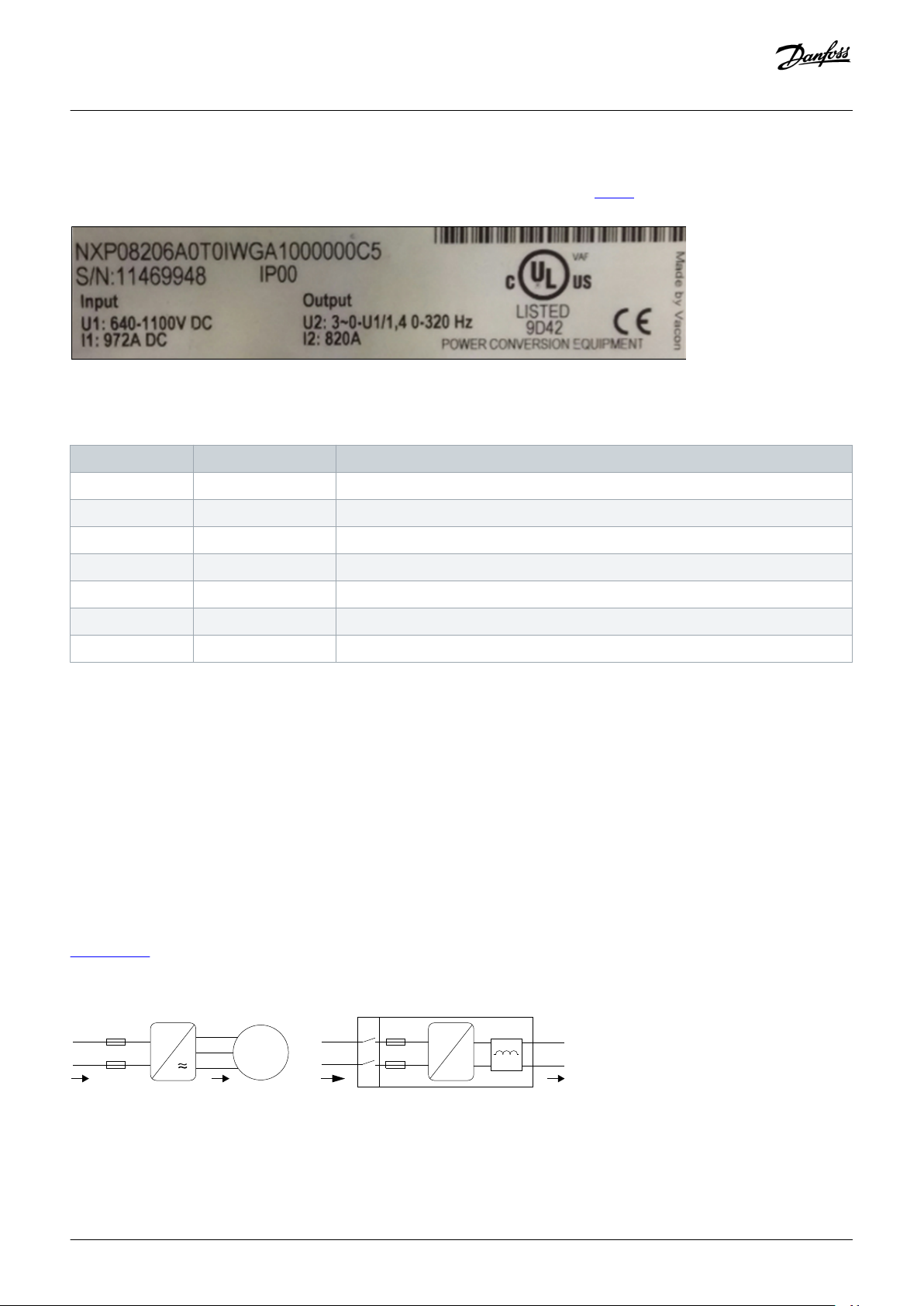
5.2 Nameplate
The VACON® NXP inverter units have a nameplate which contains the information listed in table 3.
Illustration 13: The Nameplate of a VACON® NXP Inverter
Table 3: Information Listed in a VACON® NXP Inverter Nameplate
Marking Definition Additional information
NXP08206… Type code See the VACON® NXP inverter user manual for more information
S/N Serial number Unique serial number
IP00 IP protection See the VACON® NXP inverter user manual for more information
Specifications
U1 Input voltage DC voltage
I1 Input current DC-link current (I=P/U)
U2 Output voltage 0–320 Hz
I2 Output current True RMS current
5.3 Voltage and Current Rating Guidelines
When using the VACON® NXP inverter as a VACON® NXP DCGuard™ unit, the nameplate value U1 is used as the voltage rating. In
normal operation, VACON® NXP DCGuard™ has approximately the same output DC voltage as the input DC voltage. After start-up, in
normal operation, there is no IGBT switching. The heat losses in a VACON® NXP DCGuard™ unit are therefore lower than in a normal
motor inverter.
The rated DC current of the VACON® NXP DCGuard™ is the same as the AC current rating of the VACON® NXP inverter, that is, the I2
value on the nameplate. For example, an NXP1500 inverter is rated for a 1500 A DC current when used as VACON® NXP DCGuard™ and
1500 A AC current when used as a motor inverter.
Required load current is the primary sizing criteria for VACON® NXP DCGuard™. For example, if it is required to have 500 A going from
one side of the DC bus to the other, a 500 A DCGuard is required.
illustration 14 explains the difference in voltage and current ratings when using a VACON® NXP inverter as a motor inverter and as a
VACON® NXP DCGuard™ unit.
Illustration 14: Nameplate Voltage and Current Ratings for a VACON® NXP Inverter
20 | Danfoss A/S © 2018.12
AJ284746616204en-000101 / DPD02135
Page 21
Design Guide | VACON® NXP DCGuard™
5.4 Operation Temperature Range
Air-Cooled Units
The current ratings for VACON® NXP air-cooled inverters follow these conditions:
• Maximum output current: I2 = IL. See the VACON® NXP air-cooled user manual.
• Maximum ambient temperature: 40˚C.
• Maximum ambient temperature: 40–50˚C, when derating 1.5%/˚C.
Liquid-Cooled Units
The current ratings for VACON® NXP liquid-cooled inverters follow these conditions:
• Maximum output current: I2 = ITH. See the VACON® NXP liquid-cooled user manual.
• Maximum cooling liquid temperature: 45˚C.
• Maximum ambient temperature: 50˚C.
• Maximum ambient temperature: 50–55˚C, when derating 2.5%/˚C.
5.5 Power Ratings
Specifications
5.5.1 Air-Cooled 500 V Units
Table 4: VACON® NXP DCGuard™ Power Ratings with Air-Cooled 500 V VACON® NXP Inverter Units
Type code Unit type Enclosure size DCGuard current I2 [A] DC power @800 V P
[kW]
NXP00035A2T0SSS NXP0003 FR4 3 2 10
NXP00045A2T0SSS NXP0004 FR4 4 3 15
NXP00055A2T0SSS NXP0005 FR4 5 4 19
NXP00075A2T0SSS NXP0007 FR4 7 6 25
NXP00095A2T0SSS NXP0009 FR4 9 7 33
NXP00125A2T0SSS NXP0012 FR4 12 10 40
NXP00165A2T0SSS NXP0016 FR5 16 13 53
NXP00225A2T0SSS NXP0022 FR5 22 18 70
NXP00315A2T0SSS NXP0031 FR5 31 25 101
NXP00385A2T0SSS NXP0038 FR6 38 30 136
NXP00455A2T0SSS NXP0045 FR6 45 36 167
NXP00615A2T0SSS NXP0061 FR6 61 49 202
DC
Over current and short
circuit protection, Instant trip ≤ [A]
NXP00725A2T0SSS NXP0072 FR7 72 58 268
NXP00875A2T0SSS NXP0087 FR7 87 70 317
NXP01055A2T0SSS NXP0105 FR7 105 84 383
NXP01405A2T0SSS NXP0140 FR8 140 112 462
Danfoss A/S © 2018.12
AJ284746616204en-000101 / DPD02135 | 21
Page 22
Design Guide | VACON® NXP DCGuard™
Specifications
Type code Unit type Enclosure size DCGuard current I2 [A] DC power @800 V P
[kW]
Over current and short
DC
circuit protection, Instant trip ≤ [A]
NXI01685A0T0ISF NXI0168 FI9 168 134 616
NXI02055A0T0ISF NXI0205 FI9 205 164 748
NXI02615A0T0ISF NXI0261 FI9 261 209 902
NXI03005A0T0ISF NXI0300 FI9 300 240 1078
NXI03855A0T0ISF NXI0385 FI10 385 308 1320
NXI04605A0T0ISF NXI0460 FI10 460 368 1694
NXI05205A0T0ISF NXI0520 FI10 520 416 2024
NXI05905A0T0ISF NXI0590 FI12(2×FI10) 590 472 2288
NXI06505A0T0ISF NXI0650 FI12(2×FI10) 650 520 2596
NXI07305A0T0ISF NXI0730 FI12(2×FI10) 730 584 2860
NXI08205A0T0ISF NXI0820 FI12(2×FI10) 820 656 3212
NXI09205A0T0ISF NXI0920 FI12(2×FI10) 920 736 3608
NXI10305A0T0ISF NXI1030 FI12(2×FI10) 1030 824 4048
NXI11505A0T0ISF NXI1150 FI13 1150 920 4532
NXI13005A0T0ISF NXI1300 FI13 1300 1040 5060
NXI14505A0T0ISF NXI1450 FI13 1450 1160 5720
NXI17705A0T0ISF NXI1770 FI14 1770 1416 7040
NXI21505A0T0ISF NXI2150 FI14 2150 1720 8536
NXI27005A0T0ISF NXI2700 FI14 2700 2160 10 120
5.5.2 Air-Cooled 690 V Units
Table 5: VACON® NXP DCGuard™ Power Ratings with Air-Cooled 690 V VACON® NXP Inverter Units
Type code Unit type Enclosure size DCGuard current I2 [A] DC power @1100 V P
[kW]
NXP00046A2T0SSS NXP0004 FR6 4.5 4 14
NXP00056A2T0SSS NXP0005 FR6 5.5 4 20
NXP00076A2T0SSS NXP0007 FR6 8 6 24
NXP00106A2T0SSS NXP0010 FR6 10 8 33
NXP00136A2T0SSS NXP0013 FR6 13.5 11 44
NXP00186A2T0SSS NXP0018 FR6 18 14 59
Over current and short
DC
circuit protection, Instant trip ≤ [A]
NXP00226A2T0SSS NXP0022 FR6 22 18 79
NXP00276A2T0SSS NXP0027 FR6 27 22 97
22 | Danfoss A/S © 2018.12
AJ284746616204en-000101 / DPD02135
Page 23
Design Guide | VACON® NXP DCGuard™
Specifications
Type code Unit type Enclosure size DCGuard current I2 [A] DC power @1100 V P
[kW]
Over current and short
DC
circuit protection, Instant trip ≤ [A]
NXP00346A2T0SSS NXP0034 FR6 34 27 119
NXP00416A2T0SSS NXP0041 FR7 41 33 150
NXP00526A2T0SSS NXP0052 FR7 52 42 180
NXP00526A2T0SSS NXP0062 FR8 62 50 229
NXP00526A2T0SSS NXP0080 FR8 80 64 273
NXP00526A2T0SSS NXP0100 FR8 100 80 352
NXI01256A2T0ISF NXI0125 FI9 125 100 440
NXI01446A2T0ISF NXI0144 FI9 144 115 550
NXI01706A2T0ISF NXI0170 FI9 170 136 634
NXI02056A2T0ISF NXI0208 FI9 208 166 748
NXI02616A2T0ISF NXI0261 FI10 261 209 915
NXI03256A2T0ISF NXI0325 FI10 325 260 1148
NXI03856A2T0ISF NXI0385 FI10 385 308 1430
NXI04166A2T0ISF NXI0416 FI10 416 333 1430
NXI04606A2T0ISF NXI0460 FI12(2×FI10) 460 368 1694
NXI05026A2T0ISF NXI0502 FI12(2×FI10) 502 402 2024
NXI05906A2T0ISF NXI0590 FI12(2×FI10) 590 472 2209
NXI06506A2T0ISF NXI0650 FI12(2×FI10) 650 520 2596
NXI07506A2T0ISF NXI0750 FI12(2×FI10) 750 600 2860
NXI08206A2T0ISF NXI0820 FI12(2×FI10) 820 656 2860
NXI09206A2T0ISF NXI0920 FI13 920 736 3608
NXI10306A2T0ISF NXI1030 FI13 1030 824 4048
NXI11806A2T0ISF NXI1180 FI13 1180 944 4532
NXI15006A2T0ISF NXI1500 FI14(2×FI13) 1500 1200 5720
NXI19006A2T0ISF NXI1900 FI14(2×FI13) 1900 1520 6600
NXI22506A2T0ISF NXI2250 FI14(2×FI13) 2250 1800 8360
5.5.3 Liquid-Cooled 500 V Units
Table 6: VACON® NXP DCGuard™ Power Ratings with Liquid-Cooled 500 V VACON® NXP Inverter Units
Type code Unit type Enclosure size DCGuard current I2 [A] DC power @800 V P
[kW]
Over current and short
DC
circuit protection, Instant trip ≤ [A]
NXP00165A0T0IWF NXP0016 CH3 16 13 61
Danfoss A/S © 2018.12
AJ284746616204en-000101 / DPD02135 | 23
Page 24
Design Guide | VACON® NXP DCGuard™
Specifications
Type code Unit type Enclosure size DCGuard current I2 [A] DC power @800 V P
[kW]
NXP00225A0T0IWF NXP0022 CH3 22 18 83
NXP00315A0T0IWF NXP0031 CH3 31 25 116
NXP00385A0T0IWF NXP0038 CH3 38 30 138
NXP00455A0T0IWF NXP0045 CH3 45 36 165
NXP00615A0T0IWF NXP0061 CH3 61 49 226
NXP00725A0T0IWF NXP0072 CH4 72 58 264
NXP00875A0T0IWF NXP0087 CH4 87 70 319
NXP01055A0T0IWF NXP0105 CH4 105 84 385
NXP01405A0T0IWF NXP0140 CH4 140 112 512
NXP01685A0T0IWF NXP0168 CH5 168 134 616
NXP02055A0T0IWF NXP0205 CH5 205 164 754
NXP02615A0T0IWF NXP0261 CH5 261 209 957
NXP03005A0T0IWF NXP0300 CH61 300 240 616
NXP03855A0T0IWF NXP0385 CH61 385 308 792
NXP04605A0T0IWF NXP0460 CH62 460 368 946
Over current and short
DC
circuit protection, Instant trip ≤ [A]
NXP05205A0T0IWF NXP0520 CH62 520 416 1069
NXP05905A0T0IWF NXP0590 CH62 590 472 1210
NXP06505A0T0IWF NXP0650 CH62 650 520 1334
NXP07305A0T0IWF NXP0730 CH62 730 584 1500
NXP08205A0T0IWF NXP0820 CH63 820 656 1685
NXP09205A0T0IWF NXP0920 CH63 920 736 1888
NXP10305A0T0IWF NXP1030 CH63 1030 824 2116
NXP11505A0T0IWF NXP1150 CH63 1150 920 2359
NXP13705A0T0IWF NXP1370 CH64 1370 1096 2812
NXP16405A0T0IWF NXP1640 CH64 1640 1312 3366
NXP20605A0T0IWF NXP2060 CH64 2060 1648 4229
NXP23005A0T0IWF NXP2300 CH64 2300 1840 4722
NXP24705A0T0IWF NXP2470 2×CH64 2470 1976 5073
NXP29505A0T0IWF NXP2950 2×CH64 2950 2360 6058
NXP37105A0T0IWF NXP3710 2×CH64 3710 2968 7617
NXP41405A0T0IWF NXP4140 2×CH64 4140 3312 8501
5.5.4 Liquid-Cooled 690 V Units
24 | Danfoss A/S © 2018.12
AJ284746616204en-000101 / DPD02135
Page 25
Design Guide | VACON® NXP DCGuard™
Table 7: VACON® NXP DCGuard™ Power Ratings with Liquid-Cooled 690 V VACON® NXP Inverter Units
Specifications
Type code Unit type Enclosure size DCGuard current I2 [A] DC power @1100 V
PDC [kW]
NXP01706A0T0IWF NXP0170 CH61 170 187 524
NXP02086A0T0IWF NXP0208 CH61 208 229 641
NXP02616A0T0IWF NXP0261 CH61 261 287 804
NXP03256A0T0IWF NXP0325 CH62 325 358 1001
NXP03856A0T0IWF NXP0385 CH62 385 424 1186
NXP04166A0T0IWF NXP0416 CH62 416 458 1281
NXP04606A0T0IWF NXP0460 CH62 460 506 1417
NXP05026A0T0IWF NXP0502 CH62 502 552 1546
NXP05906A0T0IWF NXP0590 CH63 590 649 1817
NXP06506A0T0IWF NXP0650 CH63 650 715 2002
NXP07506A0T0IWF NXP0750 CH63 750 825 2310
NXP08156A0T0IWF NXP0815 CH63 815 897 2510
NXP08206A0T0IWF NXP0820 CH64 820 902 2526
NXP09206A0T0IWF NXP0920 CH64 920 1012 2834
NXP10306A0T0IWF NXP1030 CH64 1030 1133 3172
Over current and short
circuit protection, Instant trip ≤ [A]
NXP11806A0T0IWF NXP1180 CH64 1180 1298 3634
NXP13006A0T0IWF NXP1300 CH64 1300 1430 4004
NXP15006A0T0IWF NXP1500 CH64 1500 1650 4620
NXP17006A0T0IWF NXP1700 CH64 1700 1870 5236
NXP18506A0T0IWF NXP1850 2×CH64 1850 2035 5698
NXP21206A0T0IWF NXP2120 2×CH64 2120 2332 6530
NXP23406A0T0IWF NXP2340 2×CH64 2340 2574 7207
NXP27006A0T0IWF NXP2700 2×CH64 2700 2970 8316
NXP31006A0T0IWF NXP3100 2×CH64 3100 3410 9548
5.6 Total Capacitance, Inductance, and Resistance
The total capacitance, inductance, and resistance for all VACON® NXP inverters are available from the nearest Danfoss Drives
representative.
The requested data is given case by case and must only be used to make a selectivity study for a system including the VACON® NXP
DCGuard™.
Danfoss A/S © 2018.12
AJ284746616204en-000101 / DPD02135 | 25
Page 26

Load
zone
Load
zone
DC+
DC-
DC+
DC-
Main DC grid
AFE
=
~
G
Sub DC grid
e30bg944.10
INU
=
~
=
~
M M
INU
DCGuard
U
V
=
=
DC+
DC-
Sub DC grid
INU
=
~
=
~
M M
INU
DCGuard
ENERGY
ENERGY
U
V
=
=
Design Guide | VACON® NXP DCGuard™
Electrical Installation Guidelines
6 Electrical Installation Guidelines
6.1 DCGuard Topologies
VACON® NXP DCGuard™ can be used to give short circuit protection in different DC-grid topologies:
• Directional topology
• Peer-to-peer topology
• Ring topology
6.1.1 Directional Topology
VACON® NXP DCGuard™ can be used to give one directional protection. The directional topology only gives short circuit protection for
a short circuit current going from the main DC grid to one of the DC subgrids.
Illustration 15: VACON® NXP DCGuard™ Directional Topology
6.1.2 Peer-to-peer Topology
To give two-directional short-circuit protection, two VACON® NXP DCGuard™ units can be connected in a peer-to-peer topology. The
connection between the two DCGuard units can be done by using two or three bus-tie cables.
The 2-cable connection is the default connection method, but also the 3-cable connection can be used if necessary.
2-Cable Connection
Connect the 2-cable connection according to the following guidelines:
• Connect the DC- bus-tie cable to the V-phase terminal in both units.
• Connect the DC+ bus-tie cable to the U-phase terminal in one unit and to the W-phase terminal in the other unit.
26 | Danfoss A/S © 2018.12
AJ284746616204en-000101 / DPD02135
Page 27

W
V
DC+
DCGuard 1
DCGuard 2
DC-
DC+
DC-
DC+
DC-
U
V
DC grid 1
AFE
INU
=
~
=
=
=
=
=
~
=
~
M
M
G
INU
DC grid 2
e30bg860.12
AFE
INU
=
~
=
~
=
~
M
M
G
INU
W
U
V
DC+
DCGuard 1
DCGuard 2
DC-
DC+
DC+
DC-
DC+
DC-
U
W
V
DC grid 1
AFE
INU
=
~
=
=
=
=
=
~
=
~
M
M
G
INU
DC grid 2
e30bg945.10
AFE
INU
=
~
=
~
=
~
M
M
G
INU
Design Guide | VACON® NXP DCGuard™
Illustration 16: VACON® NXP DCGuard™ Peer-to-peer Topology 2-Cable Connection
Electrical Installation Guidelines
3-Cable Connection
Connect the 3-cable connection according to the following guidelines:
• Connect the DC- bus-tie cable to the V-phase terminal in both units.
• Connect the first DC+ bus-tie cable to the U-phase terminal in one unit and to the W-phase terminal in the other unit.
• Connect the second DC+ bus-tie cable to the W-phase terminal in one unit and to the U-phase terminal in the other unit.
Illustration 17: VACON® NXP DCGuard™ Peer-to-peer Topology 3-Cable Connection
6.1.3 Ring Topology
Ring shaped topologies are used in some applications to connect two or more DC grids. VACON® NXP DCGuard™ can be used to form
a ring topology by using several peer-to-peer connections.
Danfoss A/S © 2018.12
AJ284746616204en-000101 / DPD02135 | 27
Page 28

W
V
DC+
DCGuard 1
DCGuard 2
DC-
DC+
DC-
DC+
DC-
U
V
DC grid 1
AFE
INU
=
~
=
=
=
=
=
~
=
~
M
M
G
INU
DC grid 2
e30bg946.10
AFE
INU
=
~
=
~
=
~
M
M
G
INU
W
V
DCGuard 4
=
=
DCGuard 3
U
V
=
=
DC-
DC+
W
V
DC+
DCGuard 3
DCGuard 4
DC-
DC+
DC-
DC+
DC-
U
V
=
=
=
=
e30bg947.10
W
V
DC+
DCGuard 1
DCGuard 2
DC-
DC+
DC-
DC+
DC-
U
V
=
=
=
=
W
V
DC+
DCGuard 5
DCGuard 6
DC-
DC+
DC-
DC+
DC-
U
V
=
=
=
=
Design Guide | VACON® NXP DCGuard™
Electrical Installation Guidelines
Illustration 18: VACON® NXP DCGuard™ Ring Topology
6.2 Parallel Installation
Two or more VACON® NXP DCGuard™ units can be installed in parallel to achieve a higher power rating. To have good current sharing
between the DCGuard units, it is important that only identical systems are installed in parallel. The parallel systems must have identical:
• DCGuard units
• Filters
• Cable types
• Cable installation
• Fuses
Illustration 19: Circuit Diagram of a Parallel Installation of Danfoss Units
6.3 Bus-Tie Cables
To connect two or more DCGuard units together, bus-tie cables are required.
Recommended specifications for the bus-tie cables:
28 | Danfoss A/S © 2018.12
AJ284746616204en-000101 / DPD02135
Page 29

DC+
A
DC+
DC- DC-
e30bg948.10
Design Guide | VACON® NXP DCGuard™
• Shielded type cable.
- The cable shield must be connected to ground at both ends.
• Symmetrical 4-wire cable.
- Two wires for DC+ and two wires for DC-.
• The cable must withstand minimum 2×DC-link voltage.
- In the worst case, the common-mode voltage is 2×DC-link voltage potential to ground.
A Cable shield
Electrical Installation Guidelines
Illustration 20: Recommended Bus-Tie Cable Type
6.4 HF Capacitors
It is recommended to connect the DC+ and DC- (clamp) of the DC grids to ground with HF capacitors. Select the size of the HF
capacitors according to the system parasitic capacitance to ground.
• 10× system parasitic capacitance ≈ 100 V common-mode voltage to ground.
• 100× system parasitic capacitance ≈ 10 V common-mode voltage to ground.
In other words, system parasitic capacitance is where the common-mode voltage causes current to PE.
The following components have leakage current to ground driven by the common-mode voltage:
• Cables between INU and motor, and the motor itself.
• Cables between grid converter and isolation transformer, and the sine-wave filter itself.
6.5 Cabling
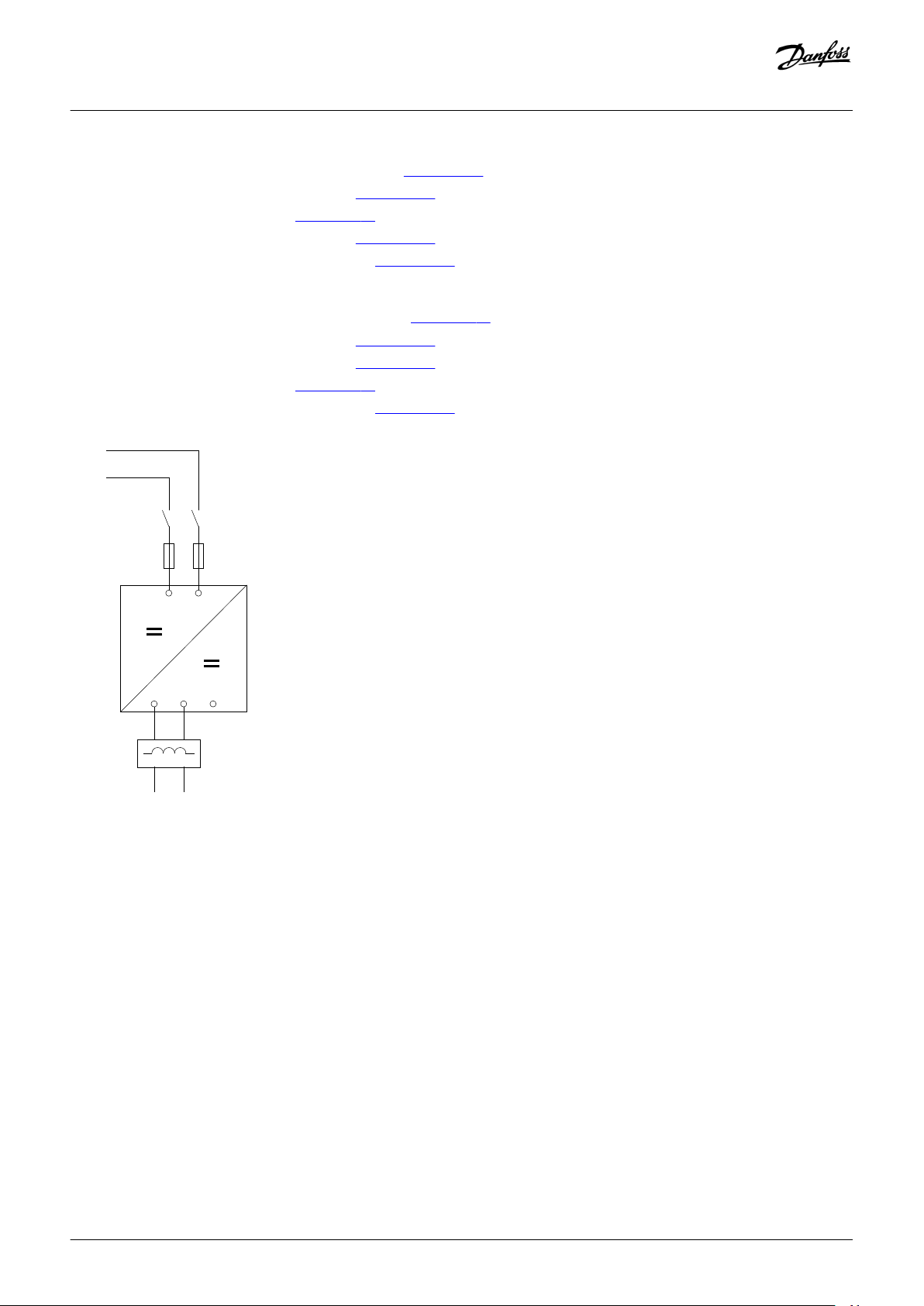
The cabling of the VACON® NXP DCGuard™ inverter units is different depending on the unit type and nominal current of the units. See:
• 6.5.1 Wiring Diagrams for Air-Cooled Inverter Units
• 6.5.2 Wiring Diagrams for Liquid-Cooled Inverter Units
Definitions for the wiring diagrams:
Item Definition
-F Fuse, type aR. See the VACON® NXP DCGuard™ design guide for instructions on fuse selection.
-K Mechanical disconnector
-L Output di/dt filter
Danfoss A/S © 2018.12
AJ284746616204en-000101 / DPD02135 | 29
Page 30

U
V
B+
-F1.1
-K1.1
-K1.2
e30bg884.10
-F1.2
-L1
DC+
DC-
DC+ DC-
B-
W
Design Guide | VACON® NXP DCGuard™
6.5.1 Wiring Diagrams for Air-Cooled Inverter Units
Wiring diagrams for air-cooled inverter units, 500 V (465–800 V DC):
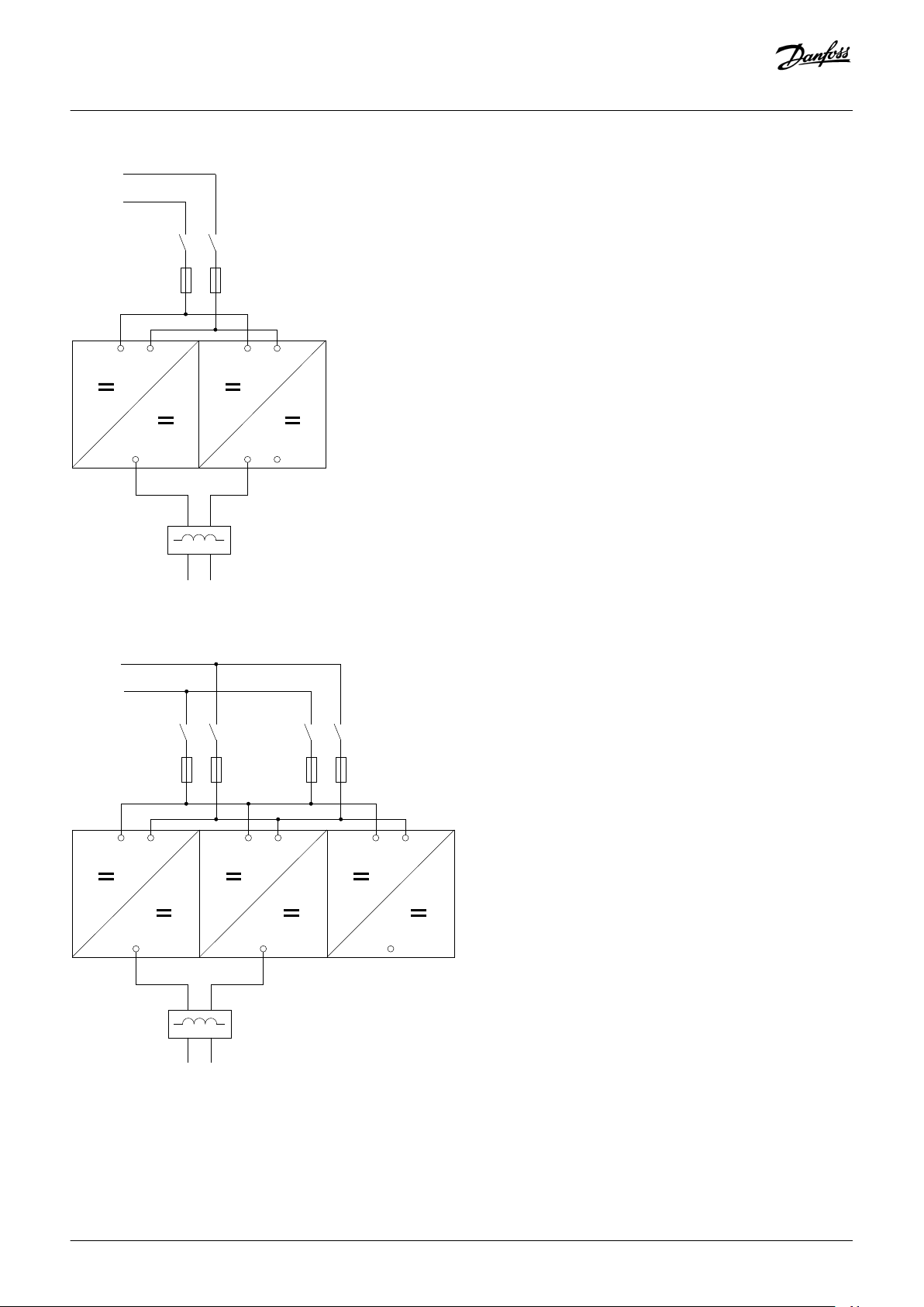
• NXP0003–NXP0520, enclosure sizes FR4 to FI10, see illustration 21.
• NXP0590–NXP0730, enclosure size FI12, see illustration 22.
• NXP0820–NXP1030, enclosure size FI12, see
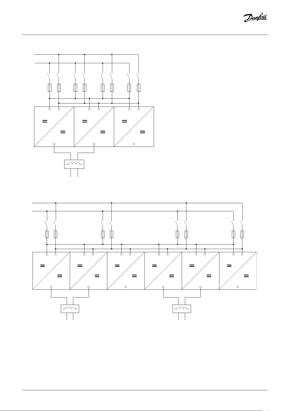
• NXP1150–NXP1450, enclosure size FI13, see illustration 24.
• NXP1770–NXP2150, enclosure size FI14, see
Wiring diagrams for air-cooled inverter units, 690 V (640–1100 V DC):
• NXP0004–NXP0416, enclosure sizes FR4 to FI10, see illustration 21.
• NXP0460–NXP0590, enclosure size FI12, see
• NXP0650–NXP0820, enclosure size FI12, see illustration 23.
• NXP0920–NXP1180, enclosure size FI13, see
• NXP1500–NXP2250, enclosure size FI14, see illustration 25.
illustration 23.
illustration 25.
illustration 22.
illustration 24.
Electrical Installation Guidelines
Illustration 21: Basic Wiring Diagram for Enclosure Sizes FR4–FI10
30 | Danfoss A/S © 2018.12
AJ284746616204en-000101 / DPD02135
Page 31

-L1
DC+
DC-
U
V
B+
B-
W U
V
B+
B-
W
-F1.1
-K1.1
-K1.2
-F1.2
-F2.1
-K2.1
-K2.2
-F2.2
DC+
DC-
e30bg885.10
-L1
-L2
U
V
B+
B-
W U
V
B+
B-
W
DC+ DC-
DC+ DC-
-F1.1
-K1.1
-K1.2
-F1.2
-F2.1
-K2.1
-K2.2
-F2.2
DC+
DC-
e30bg886.10
Design Guide | VACON® NXP DCGuard™
Electrical Installation Guidelines
Illustration 22: Basic Wiring Diagram for Enclosure Size FI12 with 1 Output Filter (only valid for 500 V NXP0590–NXP0730 and 690 V NXP0460–
NXP0590)
Illustration 23: Basic Wiring Diagram for Enclosure Size FI12 with 2 Output Filters
Danfoss A/S © 2018.12
AJ284746616204en-000101 / DPD02135 | 31
Page 32

-L1
U
B+
DC+
DC-
B-
V
B+
B-
W
B+
B-
-F1.1
-K1.1
-K1.2
-F1.2
-F2.1
-K2.1
-K2.2
-F2.2
-F3.1
-K3.1
-K3.2
-F3.2
DC+
DC-
e30bg887.10
-L1
-L2
DC+ DC- DC+ DC-
U
B+ B-
V
B+
B-
W
B+ B-
U
B+ B-
V
B+ B-
W
B+ B-
-F1.1
-K1.1
-K1.2
-F1.2 -F2.1
-K2.1 -K2.2
-F2.2
-F3.1
-K3.1
-K3.2
-F3.2
-F4.1
-K4.1
-K4.2
-F4.2 -F5.1
-K5.1
-K5.2
-F5.2 -F6.1
-K6.1
-K6.2
-F6.2
DC+
DC-
e30bg888.10
Design Guide | VACON® NXP DCGuard™
Electrical Installation Guidelines
Illustration 24: Basic Wiring Diagram for Enclosure Size FI13
Illustration 25: Basic Wiring Diagram for Enclosure Size FI14
6.5.2 Wiring Diagrams for Liquid-Cooled Inverter Units
Wiring diagrams for liquid-cooled inverter units, 500 V (465–800 V DC):
32 | Danfoss A/S © 2018.12
AJ284746616204en-000101 / DPD02135
Page 33
U
V
B+
-F1.1
-K1.1
-K1.2
e30bg884.10
-F1.2
-L1
DC+
DC-
DC+ DC-
B-
W
Design Guide | VACON® NXP DCGuard™
• NXP0016–NXP0730, enclosure sizes CH3 to CH62, see illustration 26.
• NXP0820–NXP1150, enclosure size CH63, see illustration 27.
• NXP1370, enclosure size CH64, see illustration 28.
• NXP1640–NXP2300, enclosure size CH64, see
• NXP2470–NXP4140, enclosure size 2 x CH64, see illustration 30.
Wiring diagrams for liquid-cooled inverter units, 690 V (640–1100 V DC):
• NXP0170–NXP0502, enclosure sizes CH61 to CH62, see
• NXP0590–NXP0750, enclosure size CH63, see illustration 27.
• NXP0820–NXP1500, enclosure size CH64, see
• NXP1700, enclosure size CH64, see illustration 29.
• NXP1850–NXP3100, enclosure size 2 x CH64, see
illustration 29.
illustration 26.
illustration 28.
illustration 30.
Electrical Installation Guidelines
Illustration 26: Basic Wiring Diagram for Enclosure Sizes CH3–CH62
Danfoss A/S © 2018.12
AJ284746616204en-000101 / DPD02135 | 33
Page 34
-L1
DC+ DC-
U
B+
B-
V
B+
B-
W
-F1.1
-K1.1
-K1.2
-F1.2
DC+
DC-
e30bg889.10
-L1
U
B+
DC+
DC-
B-
V
B+
B-
W
B+
B-
-F1.1
-K1.1
-K1.2
-F1.2
-F1.3
-K1.3
-K1.4
-F1.4
DC+
DC-
e30bg890.10
Design Guide | VACON® NXP DCGuard™
Electrical Installation Guidelines
Illustration 27: Basic Wiring Diagram for Enclosure Size CH63
Illustration 28: Basic Wiring Diagram for Enclosure Size CH64 with 4 Input Fuses
34 | Danfoss A/S © 2018.12
AJ284746616204en-000101 / DPD02135
Page 35
-L1
U
B+
B-
V
B+
B-
W
B+
B-
-F1.1
-K1.1
-F1.2
-K1.2
-F1.3
-K1.3
-F1.4
-K1.4
-F1.5
-K1.5
-F1.6
-K1.6
-F1.7
-K1.7
-F1.8
-K1.8
DC+
DC-
DC+
DC-
e30bg891.10
-F1.1
-K1.1
-K1.2
-F1.2
-F1.3
-K1.3
-K1.4
-F1.4
-F1.5
-K1.5
-K1.6
-F1.6
-F1.7
-K1.7
-K1.8
-F1.8
U
B+
B-
V
B+
B-
W
B+
B-
U
B+ B-
V
B+ B-
W
B+ B-
-L1
-L2
DC+
DC-
DC+ DC-
DC+
DC-
e30bg892.10
Design Guide | VACON® NXP DCGuard™
Electrical Installation Guidelines
Illustration 29: Basic Wiring Diagram for Enclosure Size CH64 with 8 Input Fuses
Illustration 30: Basic Wiring Diagram for Enclosure Size 2 x CH64
Danfoss A/S © 2018.12
AJ284746616204en-000101 / DPD02135 | 35
Page 36
U V WB-
e30bg871.10
B+
U
V WB- B+
e30bg872.10
Design Guide | VACON® NXP DCGuard™
Electrical Installation Guidelines
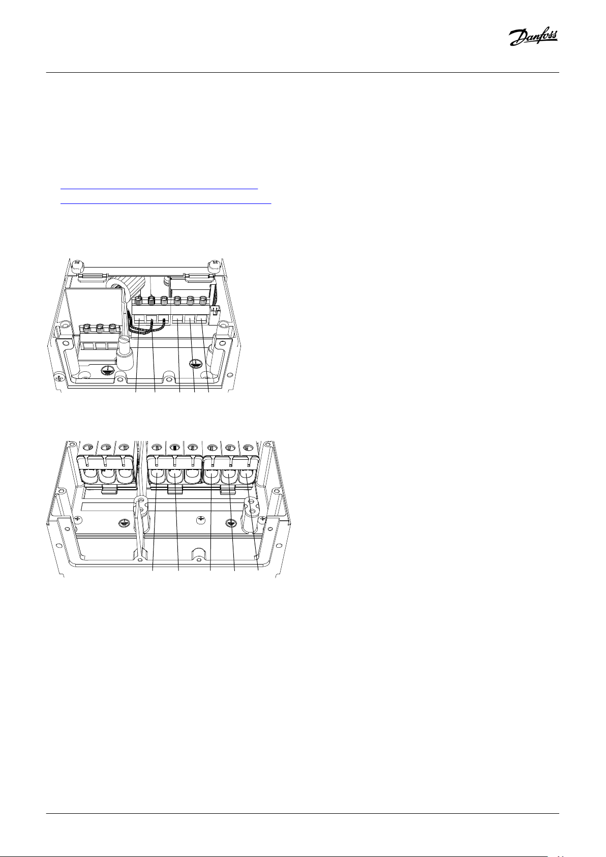
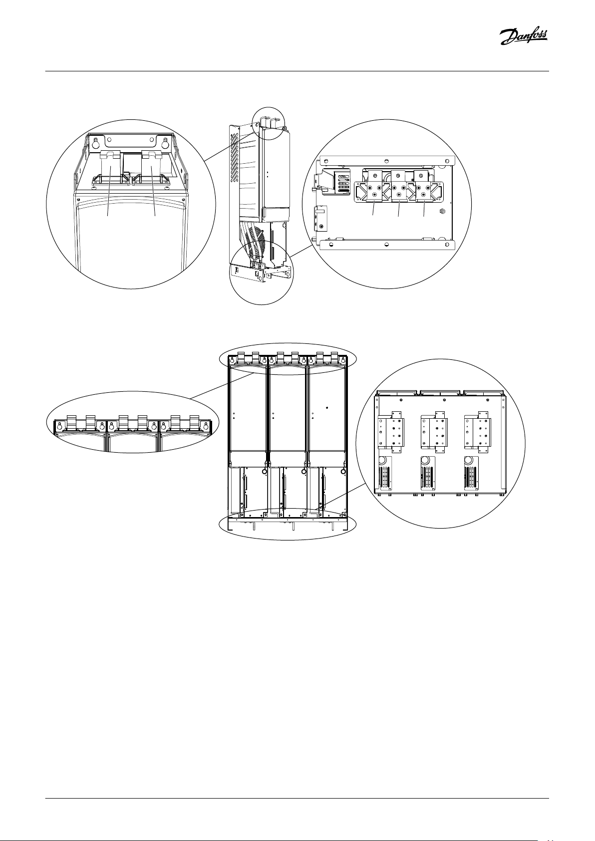
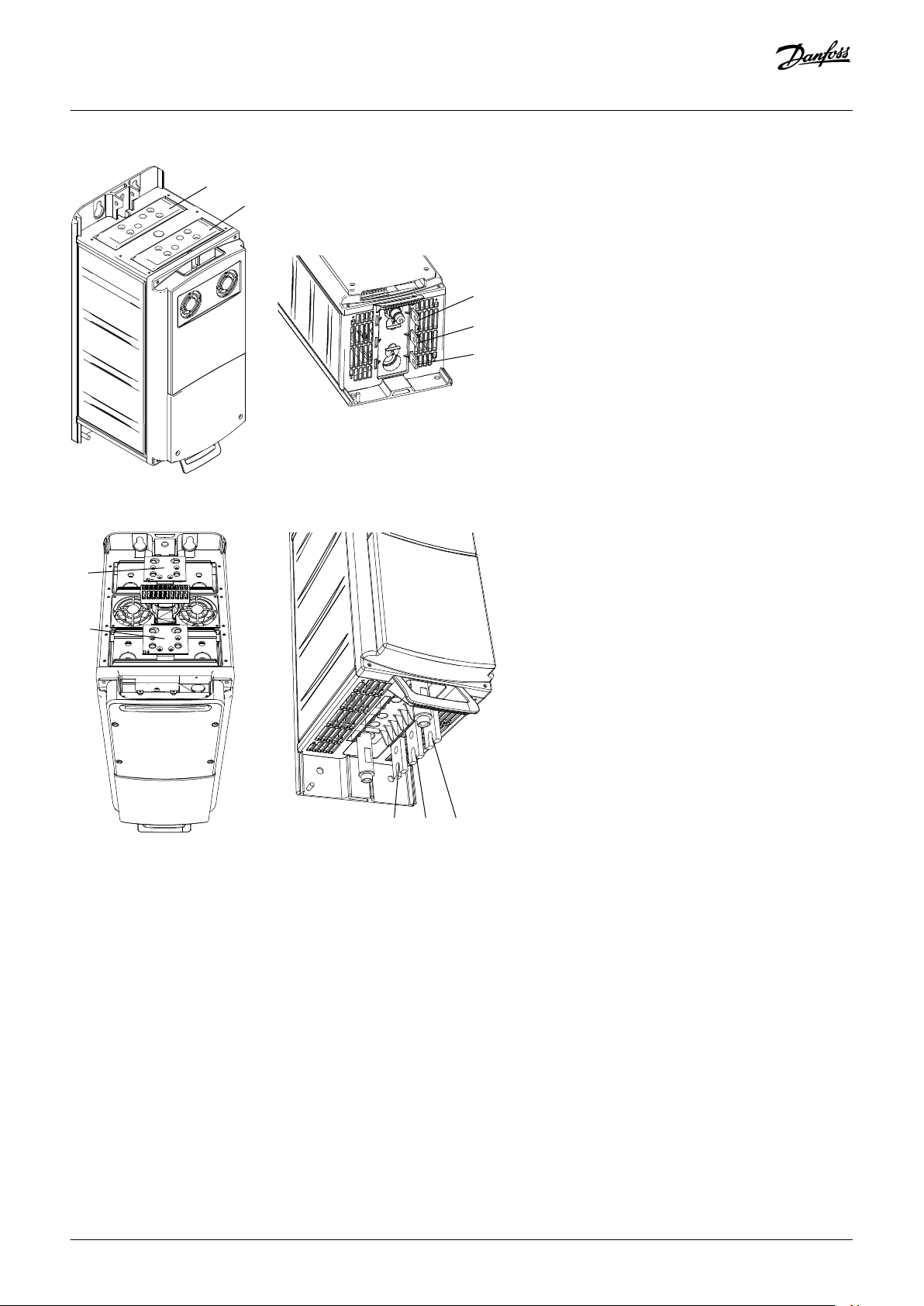
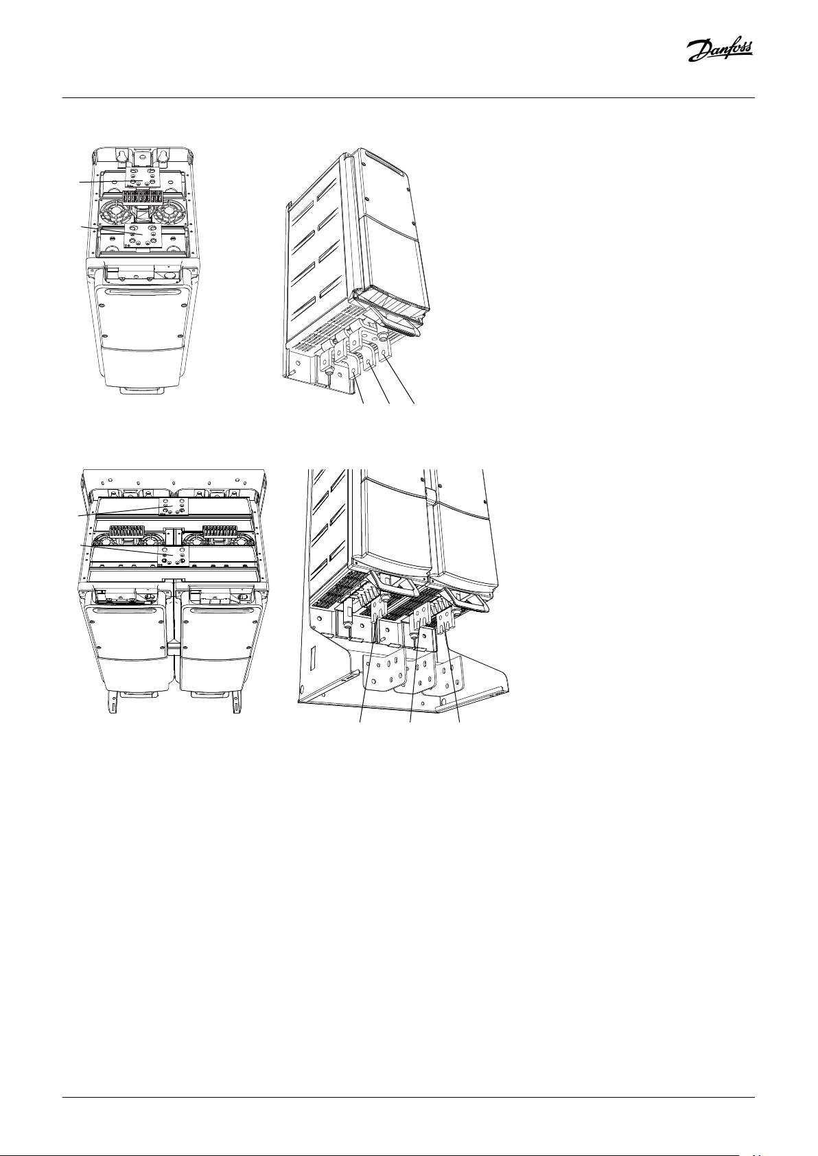
6.6 Terminal Definitions
The terminals used in the VACON® NXP DCGuard™ application are:
• DC-bus connections: Terminals B+ and B-
• Peer-to-peer connections: Terminals U, V, and W
The locations of the terminals in the different inverter unit enclosure sizes are shown in the illustrations in:
6.6.1 Terminal Locations in Air-Cooled Inverter Units
•
•
6.6.2 Terminal Locations in Liquid-Cooled Inverter Units
6.6.1 Terminal Locations in Air-Cooled Inverter Units
Illustration 31: Terminal Locations in Enclosure Sizes FR4 and FR5
Illustration 32: Terminal Locations in Enclosure Size FR6
36 | Danfoss A/S © 2018.12
AJ284746616204en-000101 / DPD02135
Page 37

U
V WB- B+
e30bg873.10
U V
W
B+
B-
e30bg874.10
Design Guide | VACON® NXP DCGuard™
Illustration 33: Terminal Locations in Enclosure Size FR7
Electrical Installation Guidelines
Illustration 34: Terminal Locations in Enclosure Size FR8
Danfoss A/S © 2018.12
AJ284746616204en-000101 / DPD02135 | 37
Page 38
B+ B-
U
V
W
e30bg875.10
U V W
B+ B-
B+
B-
B+
B-
e30bg876.10
Design Guide | VACON® NXP DCGuard™
Illustration 35: Terminal Locations in Enclosure Sizes FI9, FI10, and FI12
Electrical Installation Guidelines
Illustration 36: Terminal Locations in Enclosure Sizes FI13 and FI14
38 | Danfoss A/S © 2018.12
AJ284746616204en-000101 / DPD02135
Page 39

B- B+UV
W
e30bg877.10
B+
B-
W
V
U
e30bg878.10
Design Guide | VACON® NXP DCGuard™
6.6.2 Terminal Locations in Liquid-Cooled Inverter Units
Illustration 37: Terminal Locations in Enclosure Size CH3
Electrical Installation Guidelines
Illustration 38: Terminal Locations in Enclosure Size CH4
Danfoss A/S © 2018.12
AJ284746616204en-000101 / DPD02135 | 39
Page 40
B+
B-
U
V
W
e30bg879.10
B+
W V U
B-
e30bg880.10
Design Guide | VACON® NXP DCGuard™
Illustration 39: Terminal Locations in Enclosure Size CH5
Electrical Installation Guidelines
Illustration 40: Terminal Locations in Enclosure Size CH61
40 | Danfoss A/S © 2018.12
AJ284746616204en-000101 / DPD02135
Page 41
B+
B-
W V U
e30bg881.10
B+
U V W
B-
e30bg882.10
Design Guide | VACON® NXP DCGuard™
Illustration 41: Terminal Locations in Enclosure Size CH62
Electrical Installation Guidelines
Illustration 42: Terminal Locations in Enclosure Size CH63
Danfoss A/S © 2018.12
AJ284746616204en-000101 / DPD02135 | 41
Page 42

B+
B-
U V W
e30bg883.10
Design Guide | VACON® NXP DCGuard™
Illustration 43: Terminal Locations in Enclosure Size CH64
Electrical Installation Guidelines
6.7 Control I/O Configuration
The figure shows the default I/O configuration for the VACON® NXP DCGuard™ application and a basic description of the terminals and
signals of the I/O board.
For more information on control terminals, see the VACON® NXP DCGuard™ application guide.
42 | Danfoss A/S © 2018.12
AJ284746616204en-000101 / DPD02135
Page 43

1
6
2
3
4
5
18
READY
RUN
mA
19
20
12
7
13
8
9
10
14
15
16
21
OPTA2
22
23
11
17
24
25
26
Standard I/O board
Terminal Signal
Description
+10Vref Reference voltage output
e30bg859.10
Voltage for potentiometer, etc.
AI1+
Analog input 1
Range 0-10 V, Ri = 200 Ω
Range 0-20 mA Ri = 250 Ω
Range 0-10 V, Ri = 200 Ω
Range 0-20 mA Ri = 250 Ω
Analog input 1
Input range selected by jumpers
Default range: Voltage 0-10 V
AI1-
I/O Ground Ground for reference and controls
AI2+
Analog input 2
Analog input 2
Input range selected by jumpers
Default range: Current 0-20 mA
AI2-
+24V
Control voltage output
Voltage for switches, etc. max 0.1 A
GND
I/O ground
Ground for reference and controls
DIN1
Start Request
(Close Request)
Programmable G2.2
Contact closed = Start Request
(Contact closed = Close Request)
DIN2
Programmable G2.2
No function defined at default
DIN3
Programmable G2.2
No function defined at default
CMA
Common for DIN1-DIN3
Connect to GND or +24 V
+24V
Control voltage output
Voltage for switches (see #6)
GND
I/O ground
Ground for reference and controls
DIN4
Programmable G2.2
No function defined at default
DIN5
Programmable G2.2
No function defined at default
DIN6
Programmable G2.2
No function defined at default
CMB
Common for DIN4-DIN6
Connect to GND or +24 V
AO1+
Analog output 1
Programmable G2.3
Output range selected by jumpers
Range 0-20 mA, RL max. 500 Ω
Range 0-10 V, RL > 1 kΩ
AO1-
DO1
Digital output
Programmable G2.3
Programmable
Open collector, I ≤ 50 mA, U ≤ 48 V DC
RO1
Relay output 1
Programmable G2.3
Programmable G2.3
Switching capacity
24 V DC / 8 A
250 V AC / 8 A
125 V DC / 0.4 A
RO1
RO1
RO2
Relay output 2
Switching capacity
24 V DC / 8 A
250 V AC / 8 A
125 V DC / 0.4 A
RO2
RO2
220
VAC
Design Guide | VACON® NXP DCGuard™
Electrical Installation Guidelines
Illustration 44: The Default I/O Configuration for the VACON® NXP DCGuard™ Application
Danfoss A/S © 2018.12
AJ284746616204en-000101 / DPD02135 | 43
Page 44

e30bg949.10
Design Guide | VACON® NXP DCGuard™
How to Select the VACON® NXP
DCGuard™
7 How to Select the VACON® NXP DCGuard™
7.1 VACON® Select Web Tool
The VACON® Select Web Tool is a useful and easy-to-use tool for selecting the correct VACON® NXP DCGuard™ for applications. See
illustration 45.
The tool gives the following information:
• Recommended VACON® NXP unit
• Recommended filter (dU/dt)
• Recommended aR fuses (from VACON® NXP manuals)
• Efficiency calculation
• Drawings
The web tool is accessible to Danfoss Drives personnel and is available at
the nearest Danfoss Drives representative for more information.
http://select.corp.intra.vacon.com/sizing/login.jspx. Contact
Illustration 45: Screenshot from the VACON® Select Web Tool
44 | Danfoss A/S © 2018.12
AJ284746616204en-000101 / DPD02135
Page 45

Design Guide | VACON® NXP DCGuard™
Index
Index
2
2-cable connection 26
3
3-cable connection
27
A
Additional resources
Approvals and certifications 5
B
Bus-tie cables 28
C
Cabling
Compatibility 11
Control I/O
Controlled voltage ramp-up 10
Current rating 20
29
42
D
Directional topology
26
F
Filter impedance
Filters 15
Functional description
Fuses 14
15
H
HF capacitors
High current cut-off 10
29
N
Nameplate 20
O
Operation temperature
Overload detection
Overview 7
5
P
Parallel installation
Peer-to-peer topology 26
Power ratings
Air-cooled 500 V units
Air-cooled 690 V units 22
Liquid-cooled 500 V units
Liquid-cooled 690 V units 24
Protection functions
Purpose of the manual 5
R
Rapid current cut-off
Ratings 20
Requirements
Ring topology 27
S
Safety
8
Selectivity 7, 7
Simulation
System control principle 10
System integrator responsibilities
System selectivity 12
21
10
28
21
23
9
10
11
6
12
11
I
I/O configuration 42
Instant current cut-off 9
M
Manual version
Mechanical disconnectors
Danfoss A/S © 2018.12
16
T
Technical data
Temperature range 21
Terminals
Topologies 26
Total capacitance
5
Total inductance 25
Total resistance
AJ284746616204en-000101 / DPD02135 | 45
19
36
25
25
Page 46

Design Guide | VACON® NXP DCGuard™
V
VACON® Select web tool 44
Voltage rating 20
W
Wiring diagrams
Air-cooled inverter units 30
Liquid-cooled inverter units
32
Index
46 | Danfoss A/S © 2018.12
AJ284746616204en-000101 / DPD02135
Page 47

Design Guide | VACON® NXP DCGuard™
Danfoss A/S © 2018.12
AJ284746616204en-000101 / DPD02135 | 47
Page 48

Danfoss can accept no responsibility for possible errors in catalogues, brochures and other printed material. Danfoss reserves the right to alter its products without notice. This also applies to products
already on order provided that such alterations can be made without subsequential changes being necessary in specifications already agreed. All trademarks in this material are property of the respective
companies. Danfoss and the Danfoss logotype are trademarks of Danfoss A/S. All rights reserved.
Vacon Ltd
Member of the Danfoss Group
Runsorintie 7
65380 Vaasa
Finland
drives.danfoss.com
Danfoss A/S © 2018.12 DPD02135A
AJ284746616204en-000101/ DPD02135
*DPD02135A*
 Loading...