

Page 1
user's manual
nxl frequency converters
alcnf127
lift door application
application manual
Page 2

2 • vacon Introduction
Vacon Lift Door Application
(Software alcnf127) Ver. 1.03
INDEX
1. INTRODUCTION.................................................................................................................. 3
2. CONTROL I/O...................................................................................................................... 4
3. PARAMETER LISTS ............................................................................................................ 5
3.1 MONITORING VALUES (CONTROL KEYPAD: MENU M1) ........................................................... 5
3.2 BASIC PARAMETERS (CONTROL KEYPAD: MENU P2 Æ P2.1)................................................. 6
3.3 INPUT SIGNALS (CONTROL KEYPAD: MENU P2 Æ P2.2) ......................................................... 8
3.4 OUTPUT SIGNALS (CONTROL KEYPAD: MENU P2 Æ P2.3).................................................... 10
3.5 DRIVE CONTROL PARAMETERS (CONTROL KEYPAD: MENU P2 Æ P2.4) ............................. 11
3.6 MOTOR CONTROL PARAMETERS (CONTROL KEYPAD: MENU P2 Æ P2.5) ........................... 12
3.7 PROTECTIONS (CONTROL KEYPAD: MENU P2 Æ P2.6) ......................................................... 13
3.8 AUTORESTART PARAMETERS (CONTROL KEYPAD: MENU P2 Æ P2.7) ................................ 14
3.9 LIFT DOOR PARAMETERS (CONTROL KEYPAD: MENU P2 Æ P2.8) ....................................... 15
3.10 KEYPAD CONTROL (CONTROL KEYPAD: MENU K3) ............................................................... 16
3.11 SYSTEM MENU (CONTROL KEYPAD: MENU S6) ..................................................................... 16
3.12 EXPANDER BOARDS (CONTROL KEYPAD: MENU E7) ............................................................ 16
4. DESCRIPTION OF PARAMETERS ...................................................................................... 17
4.1 BASIC PARAMETERS................................................................................................................ 17
4.2 INPUT SIGNALS ........................................................................................................................ 22
4.3 OUTPUT SIGNALS..................................................................................................................... 26
4.4 DRIVE CONTROL ....................................................................................................................... 30
4.5 MOTOR CONTROL..................................................................................................................... 34
4.6 PROTECTIONS........................................................................................................................... 37
4.7 AUTO RESTART PARAMETERS ................................................................................................ 44
4.8 LIFT DOOR PARAMETERS ........................................................................................................ 45
4.9 KEYPAD CONTROL PARAMETERS ........................................................................................... 46
5. CONTROL SIGNAL LOGIC ................................................................................................. 47
6. FAULT TRACING............................................................................................................... 48
1
Telephone: +358-201-2121 • Fax: +358-201-212 205
Page 3

Introduction vacon • 3
Lift Door Application
1. INTRODUCTION
The Lift Door Application for Vacon NXL uses direct frequency reference from the preset speed as a
default. The direct frequency reference can be selected from the analogue inputs, fieldbus, keypad,
preset speeds or motor potentiometer.
Special parameters for Lift Door Control (Group P2.8) can be browsed and edited.
The preset speed can be defined by door position switch, including door open low speed, door open
hold, door close low speed and door close hold switches. Please find more parameter about preset
speed setting in M2.8.
Also more accelerate time and decelerate time parameters can be set at different position defined
by position switch.
The input type can be select by parameter from P2.2.22 to P2.2.28, which has normal, inversion, rise
edge and fall edge choices.
The Lift Door Application defines forward to close the door and reverse to open the door as default.
Four warning and fault codes have been added to supervise position switch. The motor will run at
safe speed once happens warning or fault.
There’re three drive run mode, demo, central system and tuning can be selected by P2.8.1. Demo
mode usually is used as demonstrate, central system mode is a standard run mode, and tuning is
used to install and test as purpose.
• Digital inputs DIN2, DIN3, (DIN4) and optional dig. Inputs DIE1, DIE2, DIE3 are freely
programmable.
• Internal and optional digital/relay and analogue outputs are freely programmable.
• Analogue input 1 can be programmed as current input, voltage input or digital input DIN4.
NOTE! If the analogue input 1 has been programmed as DIN4 with parameter 2.2.6 (AI1 Signal
Range), check that the jumper selections (
Additional functions:
• Fire mode and safe input
• Switch status and door cycle times
• Identification
• Programming wizard
• Actual value supervision function: fully programmable; off, warning, fault
• Programmable Start/Stop and Reverse signal logic
• RS485 communication as standard
• Analogue input range selection, signal scaling, inversion and filtering
• Frequency limit supervision
• Programmable start and stop functions
• DC-brake at start and stop
• Prohibit frequency area
• Programmable U/f curve and U/f optimisation
• Adjustable switching frequency
• Autorestart function after fault
• Protections and supervisions (all fully programmable; off, warning, fault):
• Current input fault
• External fault
• Output phase
• Under voltage
• Earth fault
Figure 1- 1) are correct.
• Motor thermal, stall and underload protection
• Thermistor
• Fieldbus communication
• Option board
•
Position switch
24-hour support: +358-40-8371 150 • Email: vacon@vacon.com
1
Page 4
4 • vacon Control I/O
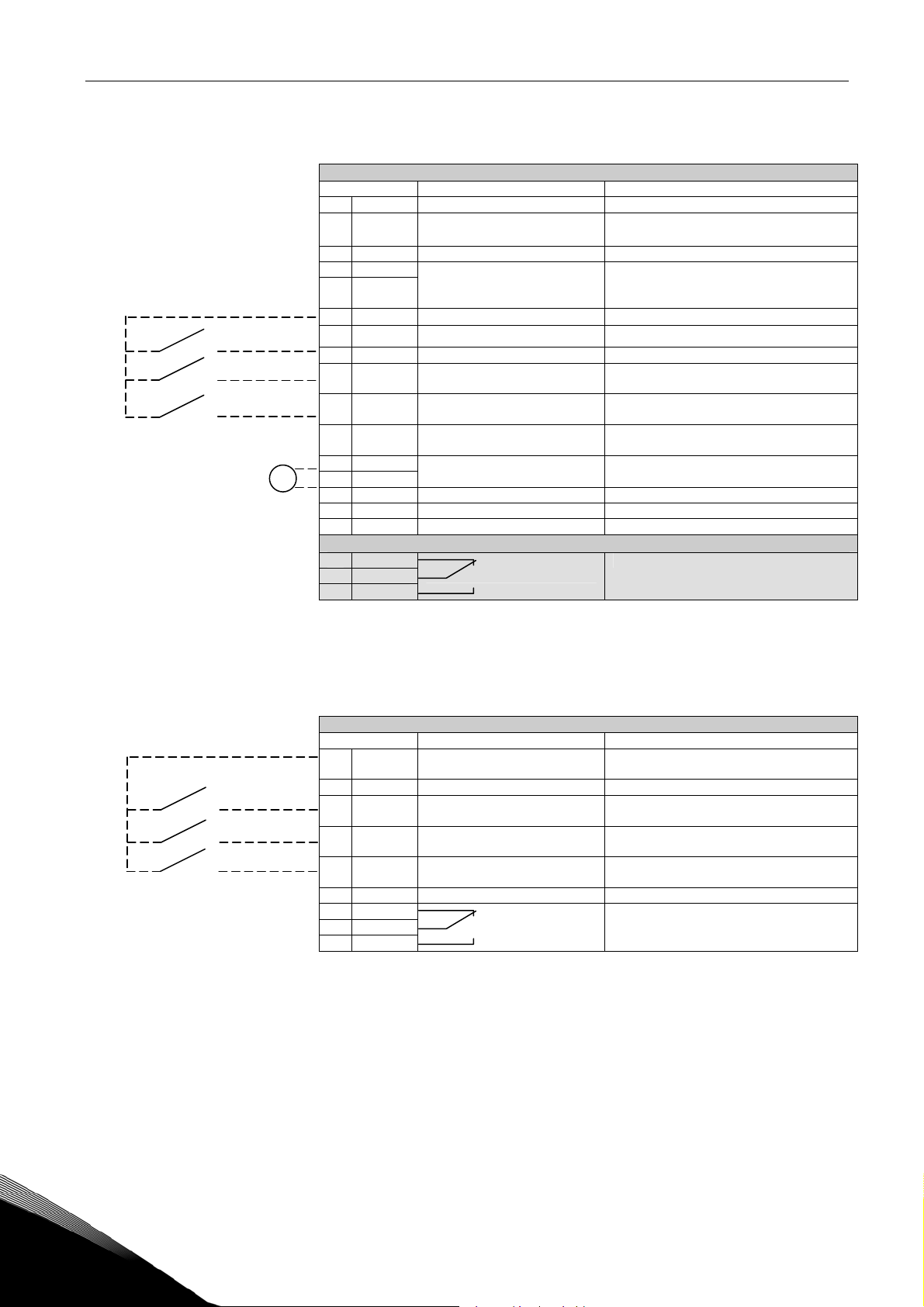
2. CONTROL I/O
Reference
Potentiometer
Terminal Signal Description
1
mA
+10V
AI1+ Analogue input, voltage range
2
3
AI1- I/O Ground Ground for reference and controls
4
AI2+
AI2-
5
/GND
6
+24V Control voltage output Voltage for switches, etc. max 0.1 A
7
GND I/O ground Ground for reference and controls
8
DIN1 Start forward Contact closed = start forward
DIN2 Start reverse (programmable) Contact closed = start reverse
9
DIN3 Open low speed
10
GND I/O ground Ground for reference and controls
11
18
AO1+
19
AO1-
A
RS 485 Serial bus Differential receiver/transmitter
B
RS 485 Serial bus Differential receiver/transmitter
30
+24V 24V aux. input voltage Control power supply backup
Reference output Voltage for potentiometer, etc.
ref
0—10V DC.
Analogue input, voltage range
0—10V DC, or current range
0/4—20mA
(programmable)
Output frequency
Analogue output
Voltage input frequency reference
Can be programmed as DIN4
Current input frequency reference
Contact closed = open low speed
Programmable
Range 0—20 mA/R
21
22
23
RO1
RO1
RO1
Relay output 1
FAULT
Programmable
Table 1- 1. Lift Door application default I/O configuration.
, max. 500Ω
L
Terminal Signal Description
+24V
1
2
GND I/O ground Ground for controls, e.g. for +24 V and DO
DIN1 Open hold
3
DIN2 Close low speed
4
DIN3 Close hold
5
6
DO1 Digital output Digital output 1
24
RO2
25
RO2
26
RO2
Control voltage output Control voltage output; voltage for witches
Relay output 2
etc, max. 150 mA
Digital input 1 (DIN4)
Digital input 2 (DIN5)
Digital input 3 (DIN6)
Programmable
RUN
Table 1- 2. OPTAA configuration.
1
Telephone: +358-201-2121 • Fax: +358-201-212 205
Page 5
Parameter lists vacon • 5
3. PARAMETER LISTS
On the next pages you will find the lists of parameters within the respective parameter groups. The
parameter descriptions are given on pages
17 to 44.
Column explanations:
Code = Location indication on the keypad; Shows the operator the present param. Number
Parameter = Name of parameter
Min = Minimum value of parameter
Max = Maximum value of parameter
Unit = Unit of parameter value; given if available
Default = Value preset by factory
Cust = Customer’s own setting
ID = ID number of the parameter (used with PC tools)
= On the parameter code: parameter value can only be changed after the FC has
been stopped.
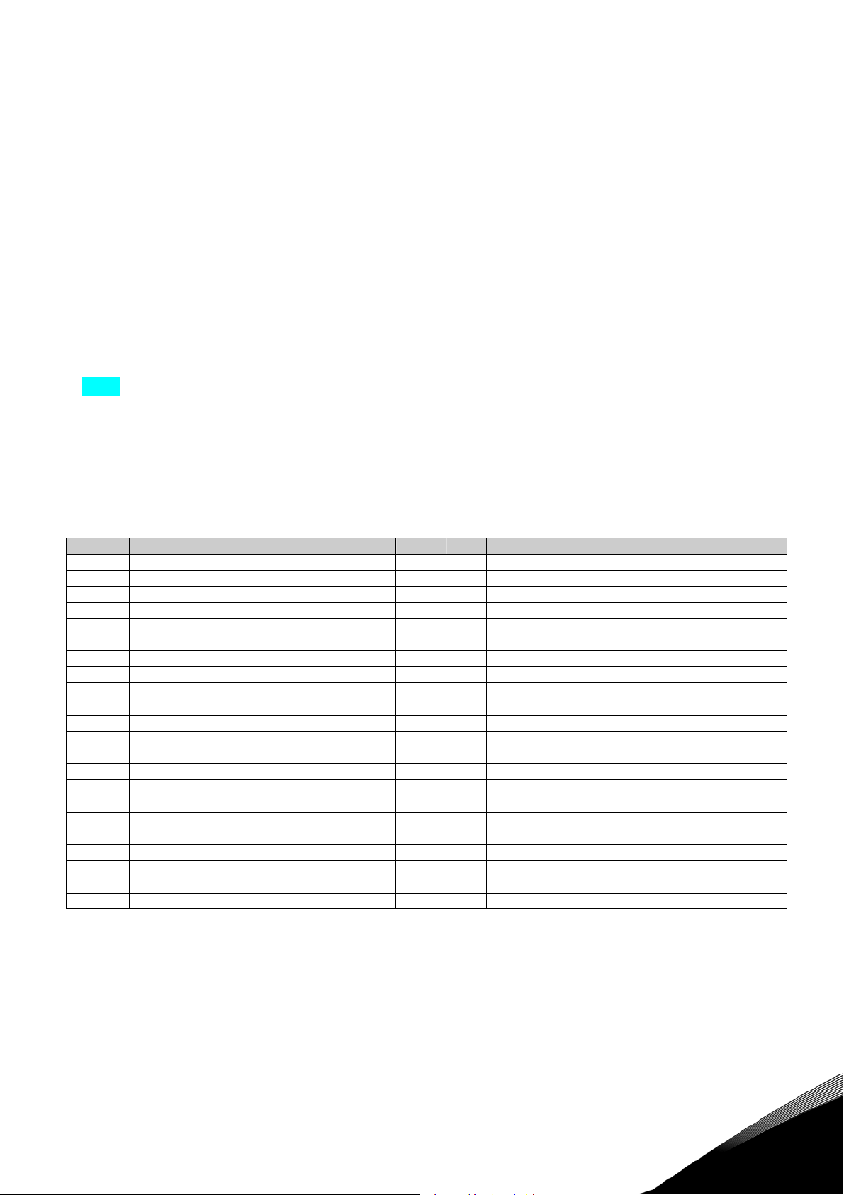
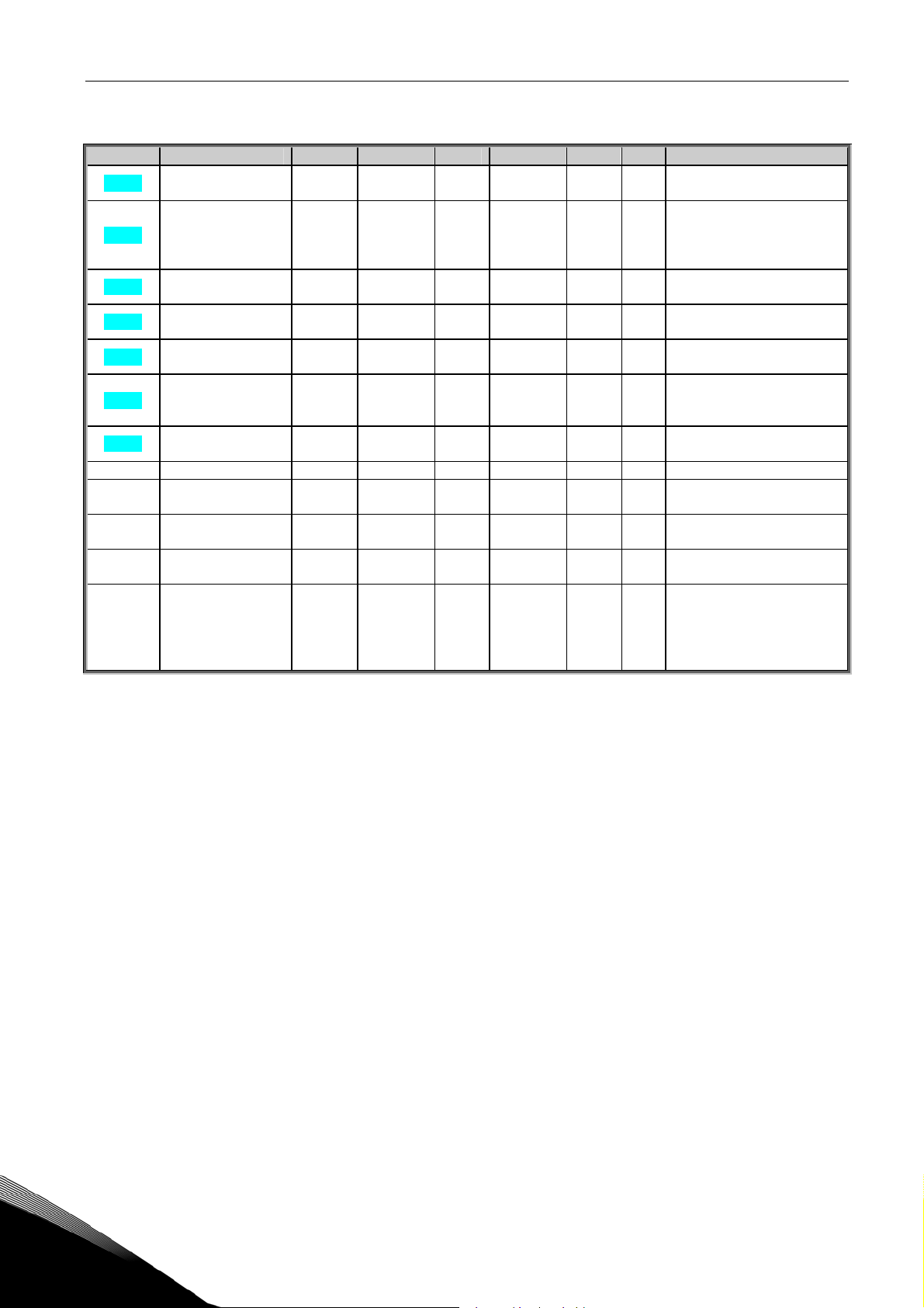
3.1 Monitoring values (Control keypad: menu M1)
The monitoring values are the actual values of parameters and signals as well as statuses and
measurements. Monitoring values cannot be edited.
See Vacon NXL User’s Manual, Chapter 7.4.1 for more information.
Code Parameter Unit ID Description
V1.1 Output frequency Hz 1 Frequency to the motor
V1.2 Frequency reference Hz 25
V1.3 Motor speed rpm 2 Calculated motor speed
V1.4 Motor current A 3 Measured motor current
V1.5 Motor torque % 4
V1.6 Motor power % 5 Calculated actual power/nom. power of the motor
V1.7 Motor voltage V 6 Calculated motor voltage
V1.8 DC-link voltage V 7 Measured DC-link voltage
V1.9 Unit temperature ºC 8 Heat sink temperature
V1.10 Analogue input 1 13 AI1
V1.11 Analogue input 2 14 AI2
V1.12 Analogue output current mA 26 AO1
V1.13 Analogue output current 1, expander board mA 31
V1.14 Analogue output current 2, expander board mA 32
V1.15 DIN1, DIN2, DIN3 15 Digital input statuses
V1.16 DIE1, DIE2, DIE3 33 I/O expander board: Digital input statuses
V1.17 RO1 34 Relay output 1 status
V1.18 ROE1, ROE2, ROE3 35 I/O exp. board: Relay output statuses
V1.19 DOE 1 36 I/O exp. board: Digital output 1 status
V1.20 Operate counter % 67 Door operate time, 0-65535
V1.21 Door DIN status % 68 The status of position switch (DIN)
Table 1- 3. Monitoring values
Calculated actual torque/nom. torque of the
motor
24-hour support: +358-40-8371 150 • Email: vacon@vacon.com
1
Page 6
6 • vacon Parameter lists
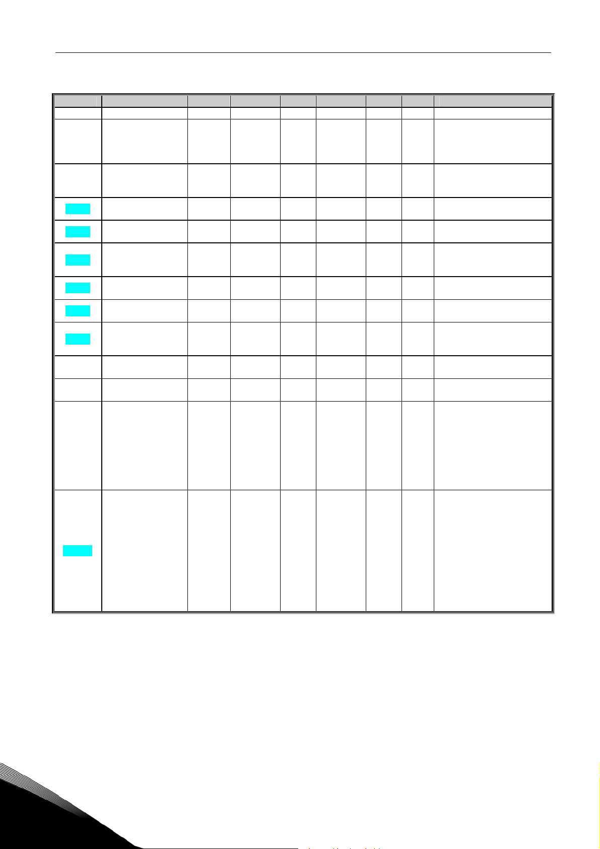
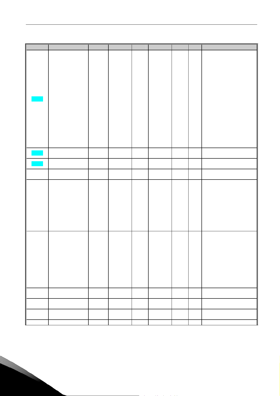
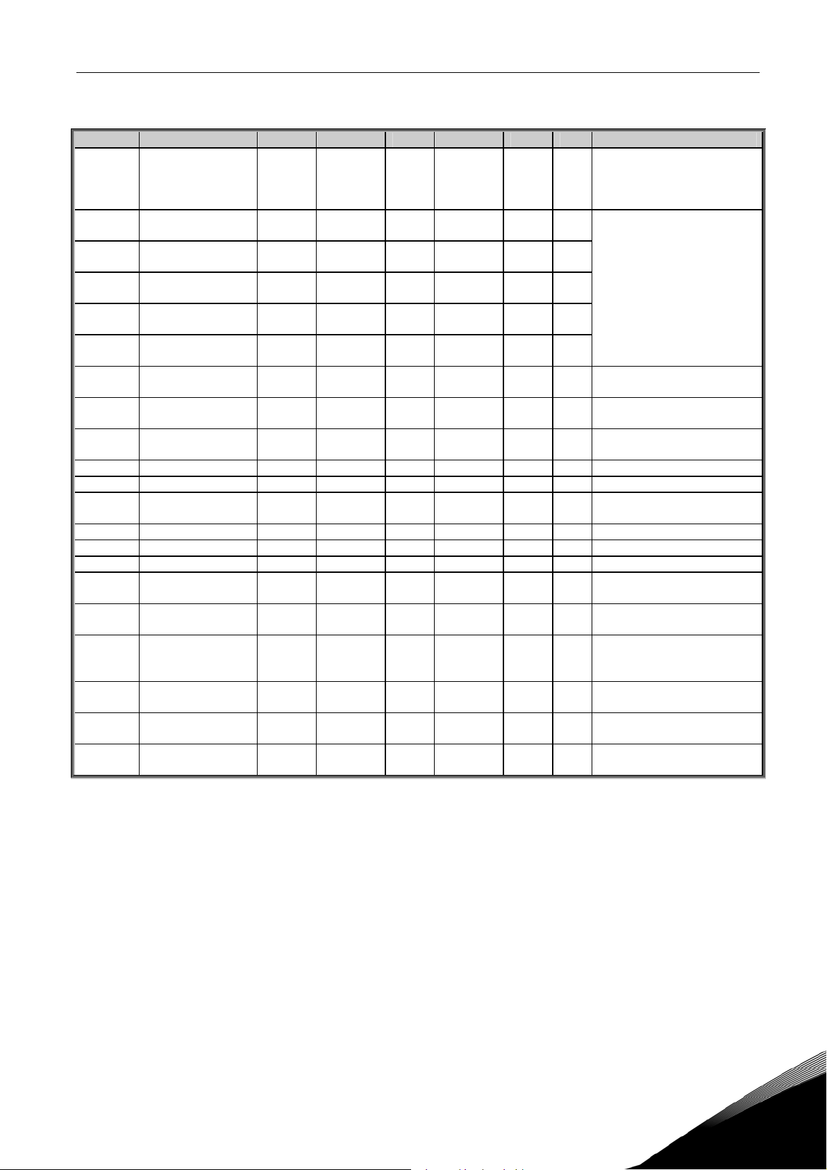
3.2 Basic parameters (Control keypad: Menu P2 Æ P2.1)
Code Parameter Min Max Unit Default Cust ID Note
P2.1.1 Min frequency 0,00 Par. 2.1.2 Hz 0,00 101
> than the
max
P2.1.2 Max frequency Par. 2.1.1 320,00 Hz 50,00
P2.1.3 Current limit 0,1 x IL 1,5 x IL A IL
P2.1.4
P2.1.5
P2.1.6
P2.1.7
P2.1.8
P2.1.9 Start function 0 2 0
P2.1.10 Stop function 0 1 0
P2.1.11 U/f optimisation 0 1 1
P2.1.12 I/O reference 0 5 6
P2.1.13 DIN2 function 0 8 1
Nominal voltage of
the motor
Nominal frequency
of the motor
Nominal speed of
the motor
Nominal current of
the motor
Motor cosϕ
180 690 V 2:230v
30,00 320,00 Hz 50,00
300 20 000 rpm 1440
0,3 x I
0,30 1,00 0,85
1,5 x IL A I
L
H
NOTE: If f
motor synchronous speed,
102
check suitability for motor
and drive system
NOTE: Formulas apply
107
approximately for
frequency converters up to
110
Check the rating plate of
111
the motor
The default applies for a 4-
112
pole motor and a nominal
size frequency converter.
Check the rating plate of
113
the motor
Check the rating plate of
120
the motor
0=Ramp
505
1=Flying start
2=Conditional flying start
0=Coasting
506
1=Ramp
0=Not used
109
1=Automatic torque boost
0=AI1
1=AI2
2=Keypad reference
3=Fieldbus reference
117
(FBSpeedReference)
4=Motor potentiometer
5=AI1/AI2 selection
6=Preset speed
0=Not used
1=Start Reverse
(DIN1=Start forward)
2=Reverse (DIN1=Start)
3=Stop pulse (DIN1=Start
319
pulse)
4=External fault, cc
5=External fault, oc
6=Run enable
7=Door open low
8= Door open hold
1
Telephone: +358-201-2121 • Fax: +358-201-212 205
Page 7

Parameter lists vacon • 7
P2.1.14 DIN3 function 0 18 6
P2.1.15 Automatic restart 0 1 0
P2.1.16 Parameter conceal 0 1 0
P2.1.17 Password 0 65535 0
Table 1- 4. Basic parameters P2.1
0=Not used
1=Reverse
2=External fault, cc
3=External fault, oc
4=Fault reset
5=Run enable
6=Door open low
7=Door open hold
8=DC-braking command
301
9=Motor pot. UP (cc)
10=Motor pot. DOWN (cc)
11=ThermFlt/Wrn
12=I/O Terminal
13=Fieldbus
14=AI1/AI2 Sel
15= Door close low
16= Door close hold
17=Fire mode
18=Safe enable
0=Not used
731
1=Used
0=All visual
854
1=Basic
0-65535
0-1=disable password
852
when access; and
password status, 0 is
disable, 1 is active
2-65535= password data
24-hour support: +358-40-8371 150 • Email: vacon@vacon.com
CP= control place
1
Page 8
8 • vacon Parameter lists
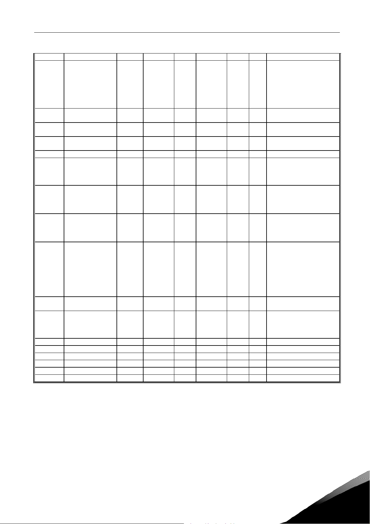
3.3 Input signals (Control keypad: Menu P2 Æ P2.2)
Code Parameter Min Max Unit Default Cust ID Note
P2.2.1
P2.2.2
P2.2.3
P2.2.4 DIN4 function (AI1)
P2.2.5
P2.2.6 AI1 signal range
P2.2.7
P2.2.8
P2.2.9 AI1 inversion
P2.2.10 AI1 filter time
Expander board DIE1
function
Expander board DIE2
function
Expander board DIE3
function
AI1 signal
selection
AI1 custom
minimum setting
AI1 custom
maximum setting
0 18 7
0 18 15
0 18 16
0
0
1
0,00
0,00
0
0,00
18 18
10
4 3
100,00 % 0,00
100,00 % 100,00
1 0
10,00 s 0,10 378 0=No filtering
0=Not used
1=Reverse
2=External fault, cc
3=External fault, oc
4=Fault reset
5=Run enable
6=Door open low
7=Door open hold
8=DC-braking command
368
9=Motor pot. UP (cc)
10=Motor pot. DOWN (cc)
11=ThermFlt/Wrn
12=I/O Terminal
13=Fieldbus
14=AI1/AI2 Select
15= Door close low
16= Door close hold
17=Fire mode
18=Safe enable
As par. 2.2.1, except:
330
13=Interlock 2
As par. 2.2.1, except:
369
13=Interlock 3
Used if P2.2.6 = 0
499
Selections as in par.2.2.3
10=AI1 (1=Local,
0=input 1)
11=AI2 (1=Local,
1= input 2)
20=Exp. AI1
377
21=Exp AI2
0=Digital input 4
1=0mA – 20mA (MF4-->)
2=4mA – 20mA (MF4-->)
3=0V – 10V
4=2V – 10V
379
Not used if AI1 Custom
min > 0% or AI1 custom
max. < 100%
Note! See NXL User’s
manual, chapter 7.4.6: AI1
mode
380
381
0=Not inverted
387
1=Inverted
(2=exp.board
0=input 1)
(2=exp.board
1=input 2)
1
Telephone: +358-201-2121 • Fax: +358-201-212 205
Page 9
Parameter lists vacon • 9
P2.2.11 AI2 signal selection
P2.2.12 AI2 signal range
P2.2.13
P2.2.14
P2.2.15 AI2 inversion
P2.2.16 AI2 filter time
P2.2.17
P2.2.18
P2.2.19
P2.2.20
P2.2.21
P2.2.22
P2.2.23 DIN 2 Type 0 3 0 741 See P2.2.22
P2.2.24 DIN 3 Type 0 3 0 742 See P2.2.22
P2.2.25 Exp DIN 1 Type 0 3 0 743 See P2.2.22
P2.2.26 Exp DIN 2 Type 0 3 0 744 See P2.2.22
P2.2.27 Exp DIN 3 Type 0 3 0 745 See P2.2.22
P2.2.28 DIN4(AI1) Type 0 3 0 746 See P2.2.22
AI2 custom
minimum setting
AI2 custom
maximum setting
Motor potentiometer
frequency reference
memory reset
Reference scaling
minimum value
Reference scaling
maximum value
Keypad control
reference selection
Fieldbus control
reference selection
DIN 1 Type 0 3 0
0
1
0,00
0,00
0
0,00
0
0,00
P2.2.18
0 5 2
0 5 3
11 388 As par. 2.2.5
4 2
100,00 % 0,00
100,00 % 100,00
1 0
10,00 s 0,10 389 0=No filtering
2 1
P2.2.19 0,00
320,00 0,00
390
391
392
398
367
344
345
121
122 See above
740
Not used if AI2 Custom
min <> 0% or AI2 custom
max. <> 100%
1=0—20 mA
2=4—20 mA
3=0V – 10V
4=2V – 10V
0=Not inverted
1=Inverted
0=No reset
1=Reset if stopped or
powered down
2=Reset if powered down
Does not affect the
fieldbus reference (Scaled
between par. 2.1.1 and
par. 2.1.2)
Does not affect the
fieldbus reference (Scaled
between par. 2.1.1 and
par. 2.1.2)
0=AI1
1=AI2
2=Keypad reference
3=Fieldbus reference
(FBSpeedreference)
4=Motor potentiometer
5=AI1/AI2 Select
6=Preset speed
0=Normal
1=Inversion
2=Rise edge
3=Fall edge
Table 1- 5. Input signals, P2.2
24-hour support: +358-40-8371 150 • Email: vacon@vacon.com
CP=control place
cc=closing contact
oc=opening contact
1
Page 10
10 • vacon Parameter lists
3.4 Output signals (Control keypad: Menu P2 Æ P2.3)
Code Parameter Min Max Unit Default Cust ID Note
P2.3.1 Relay output 1 function 0 17 16
P2.3.2
P2.3.3
P2.3.4
P2.3.5 Analogue output function 0 12 1
P2.3.6
P2.3.7
P2.3.8
P2.3.9 Analogue output scale 10 1000 % 100 311
P2.3.10
P2.3.11
P2.3.12
P2.3.13
P2.3.14
P2.3.15 AI supervision OFF limit 0,00 100,00 % 10,00 357
P2.3.16 AI supervision ON limit 0,00 100,00 % 90,00 358
P2.3.17 Relay output 1 ON delay 0,00 320,00 s 0,00 487 ON delay for RO1
P2.3.18 Relay output 1 OFF delay 0,00 320,00 s 0,00 488 OFF delay for RO1
Expander board relay
output 1 function
Expander board relay
output 2 function
Expander board digital
output 1 function
Analogue output filter
time
Analogue output
inversion
Analogue output
minimum
Expander board analogue
output 1 function
Expander board analogue
output 2 function
Output frequency limit 1
supervision
Output frequency limit 1;
Supervised value
Analogue input
supervision
0 17 17
0 17 3
0 17 1
0,00 10,00 s 1,00
0 1 0
0 1 0
0 12 0 472 As parameter 2.1.14
0 12 0
0 2 0
0,00 Par. 2.1.2 Hz 0,00
0 2 0
Table 1- 6. Output signals, G2.3
0=Not used
1=Ready
2=Run
3=Fault
4=Fault inverted
5=FC overheat warning
6=Ext. fault or warning
7=Ref. fault or warning
8=Warning
313
9=Reversed
10=Preset speed
11=At speed
12=Mot. regulator active
13=OP freq. limit superv.1
14=Control place: IO
15=Thermistor fault/
warning
16=Open end
17=Close end
314 As parameter 2.3.1
317 As parameter 2.3.1
312 As parameter 2.3.1
307
See par. 2.1.14
308 0=No filtering
0=Not inverted
309
1=Inverted
0=0 mA
310
1=4 mA
479 As parameter 2.1.14
0=No limit
315
1=Low limit supervision
2=High limit supervision
316
0=Not used
356
1=AI1
2=AI2
1
Telephone: +358-201-2121 • Fax: +358-201-212 205
Page 11
Parameter lists vacon • 11
3.5 Drive control parameters (Control keypad: Menu P2 Æ P2.4)
Code Parameter Min Max Unit Default Cust ID Note
P2.4.1 Ramp 1 shape 0,0 10,0 s 0,0
P2.4.2 Brake chopper 0 3 0
P2.4.3 DC braking current 0,15 x In 1,5 x In A Varies 507
P2.4.4
P2.4.5
P2.4.6
P2.4.7 Flux brake 0 1 0
P2.4.8 Flux braking current 0,0 Varies A 0,0 519
DC braking time
at stop
Frequency to start
DC braking during
ramp stop
DC braking time
at start
0,00 600,00 s 0,00
0,10 10,00 Hz 1,50
0,00 600,00 s 0,00
Table 1- 7. Drive control parameters, P2.4
0=Linear
500
>0=S-curve ramp time
0=Disabled
1=Used in Run state
504
3=Used in Run and Stop
state
508 0=DC brake is off at stop
515
516 0=DC brake is off at start
0=Off
520
1=On
24-hour support: +358-40-8371 150 • Email: vacon@vacon.com
1
Page 12
12 • vacon Parameter lists
3.6 Motor control parameters (Control keypad: Menu P2 Æ P2.5)
Code Parameter Min Max Unit Default Cust ID Note
P2.5.1 Motor control mode 0 1 0
P2.5.2 U/f ratio selection 0 3 0
P2.5.3
P2.5.4
P2.5.5
P2.5.6
P2.5.7
P2.5.8 Switching frequency 1,0 16,0 kHz 6,0 601 Depends on kW
P2.5.9
P2.5.10
P2.5.11 Identification 0 1 0
P2.5.12 MeasRsVoltDrop 0 2000 % 0
Field weakening
point
Voltage at field
weakening point
U/f curve midpoint
frequency
U/f curve midpoint
voltage
Output voltage at
zero frequency
Overvoltage
controller
Undervoltage
controller
30,00 320,00 Hz 50,00
10,00
0,00
0,00 100,00 % 100,00
0,00 40,00 % 0,00
0 1 1
0 1 1
200,00 % 100,00
par.
P2.5.3
Hz 50,00
Table 1- 8. Motor control parameters, P2.6
0=Frequency control
600
1=Speed control
0=Linear
1=Squared
108
2=Programmable
3=Linear with flux optim.
602
603 n% x U
604
n% x U
605
Parameter max. value =
par. 2.5.4
606 n% x U
0=Not used
607
1=Used
0=Not used
608
1=Used
0=No action
631
1=ID no run
Measured Voltage drop at
stator resistance between
866
two phases with nom
current of motor. Unit:
256=10%
nmot
nmot
nmot
1
Telephone: +358-201-2121 • Fax: +358-201-212 205
Page 13
Parameter lists vacon • 13
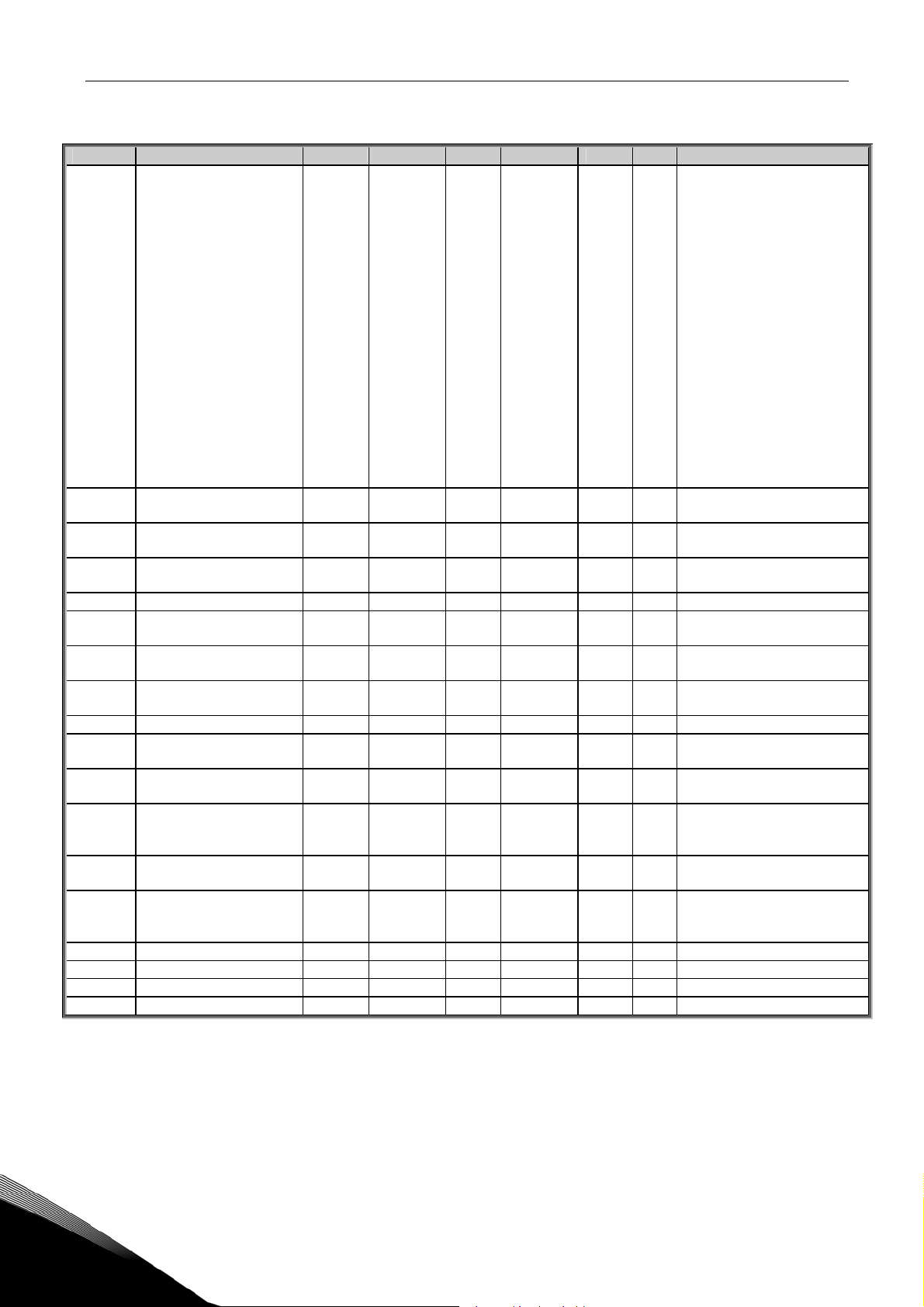
3.7 Protections (Control keypad: Menu P2 Æ P2.6)
Code Parameter Min Max Unit Default Cust ID Note
P2.6.1
P2.6.2
P2.6.3
P2.6.4
P2.6.5
P2.6.6
P2.6.7
P2.6.8
P2.6.9
P2.6.10 Motor duty cycle 0 100 % 100 708
P2.6.11 Stall protection 0 3 1 709 As par. 2.6.1
P2.6.12 Stall current limit 0,1 I
P2.6.13 Stall time limit 1,00 120,00 s 15,00 711
P2.6.14 Stall frequency limit 1,0 P 2.1.2 Hz 25,0 712
P2.6.15 Underload protection 0 3 0 713 As par. 2.6.1
P2.6.16
P2.6.17
P2.6.18
P2.6.19
P2.6.20
P2.6.21
Response to 4mA
reference fault
Response to external
fault
Response to
undervoltage fault
Output phase
supervision
Earth fault
protection
Thermal protection
of the motor
Motor ambient
temperature factor
Motor cooling factor
at zero speed
Motor thermal time
constant
Underload curve at
nominal frequency
Underload curve at
zero frequency
Underload
protection time
limit
Response to
thermistor fault
Response to
fieldbus fault
Response to slot
fault
0 3 0
0 3 2
1 3 2
0 3 2
0 3 2
0 3 0
–100,0 100,0 % 0,0
0,0 150,0 % 40,0
1 200 min 45
I
x 2 A
nmotor
10,0 150,0 % 50,0
5,0 150,0 % 10,0
2,00 600,00 s 20,00
0 3 2
0 3 2
0 3 2
nmotor
x1.3
Table 1- 9. Protections, P2.6
0=No response
1=Warning
700
2=Fault,stop acc. to 2.1.10
3=Fault,stop by coasting
701
727
0=No response
1=Warning
702
2=Fault,stop acc. to 2.1.10
3=Fault,stop by coasting
703
704
705
706
707
710
714
715
716
732 As par. 2.6.1
733 As par. 2.6.1
734 As par. 2.6.1
24-hour support: +358-40-8371 150 • Email: vacon@vacon.com
1
Page 14

14 • vacon Parameter lists
3.8 Autorestart parameters (Control keypad: Menu P2 Æ P2.7)
Code Parameter Min Max Unit Default Cust ID Note
P2.7.1 Wait time 0,10 10,00 s 0,50 717
P2.7.2 Trial time 0,00 60,00 s 30,00 718
P2.7.3 Start function 0 2 0
Table 1- 10. Autorestart parameters, P2.7
0=Ramp
719
1=Flying start
2=According to par. 2.1.9
1
Telephone: +358-201-2121 • Fax: +358-201-212 205
Page 15
Parameter lists vacon • 15
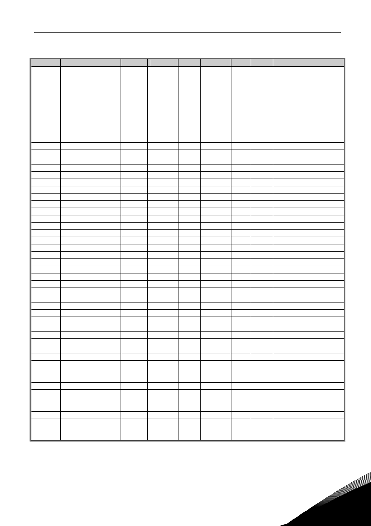
3.9 Lift door parameters (Control keypad: Menu P2 Æ P2.8)
Code Parameter Min Max Unit Default Cust ID Note
P2.8.1 Door Run Mode 0 2 2
P2.8.2 Open Start Acc.T 0.1 10.0 s 2.0 747 Open start acc. time
P2.8.3 Open Start Time 0.01 10.00 s 1.00 748 Open start time
P2.8.4 Open Start Speed 0.00 P2.1.2 Hz 5.00 749 Open start speed
P2.8.5 Open Norm Acc.T 0.1 10.0 s 2.0 750 Open normal acc. time
P2.8.6 Open Norm Speed 0.00 P2.1.2 Hz 20.00 751 Open normal speed
P2.8.7 Open Low Dec.T 0.1 10.0 s 2.0 752 Open low dec. time
P2.8.8 Open Low Speed 0.00 P2.1.2 Hz 8.00 753 Open low speed
P2.8.9 Open Hold Dec.T 0.1 10.0 s 2.0 754 Open hold dec. time
P2.8.10 Open Hold Time 0.01 10.00 s 2.00 755 Open hold time
P2.8.11 Open Hold Low 0.00 P2.1.2 Hz 3.00 756 Open hold low speed
P2.8.12 Open Hold Time1 0.01 10.00 s 0.20 757 Open hold time 1
P2.8.13 Open Hold Acc.T 0.1 10.0 s 2.0 758 Open hold acc. time
P2.8.14 Open Hold High 0.00 P2.1.2 Hz 8.00 759 Open hold high speed
P2.8.15 Open Hold Time2 0.01 10.00 s 1.00 760 Open hold time 2
P2.8.16 OpenHoldHighDecT 0.1 10.0 s 2.0 761 Open hold high dec. time
P2.8.17 Open Force Freq 0.00 P2.1.2 Hz 5.00 781 Open force frequency, Hz
P2.8.18 Open Force Torq 0.01 10.00 % 50.0 762 Open force torque limit
P2.8.19 Open Force Time 0.01 10.00 s 0.30 763 Open force keep time
P2.8.20 Open Superv Time 0.01 10.00 s 10.00 779 Open switch sup. time
P2.8.21 Open Safe Speed 5.00 P2.1.2 Hz 5.00 785 Open safe speed
P2.8.22 Close Start Acc.T 0.1 10.0 s 2.0 764 Close start acc. time
P2.8.23 Close Start Time 0.01 10.00 s 1.00 765 Close start time
P2.8.24 Close Start Speed 0.00 P2.1.2 Hz 5.00 766 Close start speed
P2.8.25 Close Norm Acc.T 0.1 10.0 s 2.0 767 Close normal acc. time
P2.8.26 Close Norm Speed 0.00 P2.1.2 Hz 20.00 768 Close normal speed
P2.8.27 Close Low Dec.T 0.1 10.0 s 2.0 769 Close low dec. time
P2.8.28 Close Low Speed 0.00 P2.1.2 Hz 8.00 770 Close low speed
P2.8.29 Close Hold Dec.T 0.1 10.0 s 2.0 771 Close hold dec. time
P2.8.30 Close Hold Time 0.01 10.00 s 2.00 772 Close hold time
P2.8.31 Close Hold Low 0.00 P2.1.2 Hz 3.00 773 Close hold low speed
P2.8.32 Close Hold Time1 0.01 10.00 s 0.2 774 Close hold time 1
P2.8.33 Close Hold Acc.T 0.1 10.0 s 2.0 775 Close hold acc. time
P2.8.34 Close Hold High 0.00 P2.1.2 Hz 8.00 776 Close hold high speed
P2.8.35 Close Hold Time2 0.01 10.00 s 1.00 777 Close hold time 2
P2.8.36 ClosHoldHighDecT 0.1 10.0 s 0.2 778 Close hold high dec. time
P2.8.37 Close Superv Time 0.01 10.00 s 10.00 780 Close switch sup. time
P2.8.38 Close Safe Speed 0 P2.1.2 Hz 5.00 784 Close safe speed
P2.8.39 Hold Freq Ref 0 P2.1.2 Hz 2.00 783 Open/close hold speed
P2.8.40 Tuning Freq Ref 0 P2.1.2 Hz 5.00 782 Tuning frequency ref.
P2.8.41 Op. Counter clear 0 1 0
851
853
Table 1- 11. Lift door parameters, P2.8
0=Demo mode
1=Central system
2=Tuning
Note, demo and tuning
mode, the start request is
from start button,
reverse request is from
left button。Demo mode
is used to demonstrate,
and tuning is used to
identify motor direction
0=Not used
1=Clear, 0->1 trigger
24-hour support: +358-40-8371 150 • Email: vacon@vacon.com
1
Page 16

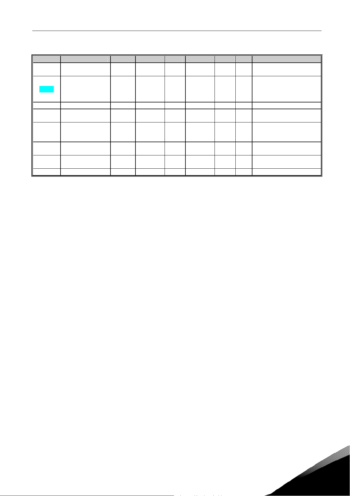
16 • vacon Parameter lists
3.10 Keypad control (Control keypad: Menu K3)
The parameters for the selection of control place and direction on the keypad are listed below. See
the Keypad control menu in the Vacon NXL User’s Manual.
Code Parameter Min Max Unit Default Cust ID Note
P3.1 Control place 1 3 1
R3.2 Keypad reference
P3.3 Direction (on keypad) 0 1 0
R3.4 Stop button 0 1 1
Par.
2.1.1
Par. 2.1.2 Hz
1 = I/O terminal
125
2 = Keypad
3 = Fieldbus
0 = Forward
123
1 = Reverse
0=Limited function of Stop
button
114
1=Stop button always
enabled
Table 1- 12. Keypad control parameters, M3
3.11 System menu (Control keypad: Menu S6)
For parameters and functions related to the general use of the frequency converter, such as
customised parameter sets or information about the hardware and software, see Chapter 7.4.6 in
the Vacon NXL User’s Manual.
3.12 Expander boards (Control keypad: Menu E7)
The E7 menu shows the expander boards attached to the control board and board-related
information. For more information, see Chapter 7.4.7 in the Vacon NXL User’s Manual.
1
Telephone: +358-201-2121 • Fax: +358-201-212 205
Page 17

Description of parameters vacon • 17
4. DESCRIPTION OF PARAMETERS
4.1 BASIC PARAMETERS
2.1.1, 2.1.2 Minimum/maximum frequency
Defines the frequency limits of the frequency converter.
The maximum value for parameters 2.1.1 and 2.1.2 is 320 Hz.
The software will automatically check the values of parameters,
2.1.3 Current limit
This parameter determines the maximum motor current from the frequency converter.
To avoid motor overload, set this parameter according to the rated current of the motor.
The current limit is equal to the rated converter current (I
2.1.4 Nominal voltage of the motor
Find this value Un on the rating plate of the motor. This parameter sets the voltage at the
field weakening point (
parameter 2.5.4) to 100% x U
2.1.5 Nominal frequency of the motor
Find this value fn on the rating plate of the motor. This parameter sets the field
weakening point (
parameter 2.5.3) to the same value.
2.1.6 Nominal speed of the motor
nmotor
2.3.13, 2.5.3, 2.5.5.
) by default.
L
.
Find this value nn on the rating plate of the motor.
2.1.7 Nominal current of the motor
Find this value In on the rating plate of the motor.
2.1.8 Motor cos phi
Find this value “cos phi” on the rating plate of the motor.
24-hour support: +358-40-8371 150 • Email: vacon@vacon.com
1
Page 18

18 • vacon Description of parameters
2.1.9 Start function
Ramp:
0 The frequency converter starts from 0 Hz and accelerates to maximum
frequency within the set
prolonged acceleration times).
Flying start:
1 The frequency converter is able to start into a running motor by applying a
small torque to motor and searching for the frequency corresponding to the
speed the motor is running at. The searching starts from the maximum
frequency towards the actual frequency until the correct value is detected.
Thereafter, the output frequency will be increased / decreased to the set
reference value according to the set acceleration/deceleration parameter
Use this mode if the motor is coasting when the start command is given. With
the flying start, it is possible to ride through short mains voltage interruptions.
P2.8. (Load inertia or starting friction may cause
Conditional flying start
2 With this mode it is possible to disconnect and connect the motor from the
frequency converter even when the Start command is active. On re-connecting
the motor, the drive will operate as described in selection 1
2.1.10 Stop function
Coasting:
0 The motor coasts to a halt without control from the frequency converter after
Ramp:
1 After the Stop command, the speed of the motor is decelerated according to
the Stop command.
the set deceleration parameters.
If the regenerated energy is high it may be necessary to use an external
braking resistor for faster deceleration.
1
Telephone: +358-201-2121 • Fax: +358-201-212 205
Page 19

Description of parameters vacon • 19
2.1.11 U/f optimisation
0 Not used
1 Automatic torque boost
The voltage to the motor changes automatically which makes the
motor produce sufficient torque to start and run at low
frequencies. The voltage increase depends on the motor type and
power. Automatic torque boost can be used in applications where
starting torque due to starting friction is high, e.g. in conveyors.
NOTE!
In high torque – low speed applications – it is likely that the motor
will overheat. If the motor has to run a prolonged time under these
conditions, special attention must be paid to cooling the motor. Use
external cooling for the motor if the temperature tends to rise too
high.
2.1.12 I/O Reference selection
Defines the selected frequency reference source when the drive is controlled from the
I/O terminal.
0 AI1 reference (terminals 2 and 3, e.g. potentiometer)
1 AI2 reference (terminals 4 and 5, e.g. transducer)
2 Keypad reference (parameter
3 Reference from Fieldbus (FBSpeedReference)
4 Motor potentiometer reference
5 AI1/AI2 selection. Selection of AI2 is made programmable by DIN3 Function (
2.1.13 DIN2 function
This parameter has 9 selections. If digital input DIN2 need not be used, set the
parameter value to 0.
3.2)
P2.1.16)
1 Start reverse
2 Reverse
3 Stop pulse
4 External fault
Contact closed: Fault is displayed and motor stopped when the input is active
5 External fault
Contact open: Fault is displayed and motor stopped when the input is not active
6 Run enable
Contact open: Start of motor disabled
Contact closed: Start of motor enabled
Coast stop if dropped during RUN
7 Door open low
8 Door open hold
Contact closed: door open hold switch on.
24-hour support: +358-40-8371 150 • Email: vacon@vacon.com
1
Page 20

20 • vacon Description of parameters
2.1. 14 DIN3 function
The parameter has 19 selections. If digital input DIN3 need not be used, set the param.
Value to 0.
1 Reverse
Contact open: Forward
Contact closed: Reverse
2 External fault
Contact closed: Fault is displayed and motor stopped when the input is active
3 External fault
Contact open: Fault is displayed and motor stopped when the input is not active
4 Fault reset
Contact closed: All faults reset
5 Run enable
Contact open: Start of motor disabled
Contact closed: Start of motor enabled
Coast stop if dropped during RUN
6 Door open low
7 Door open hold
8 DC braking command
Contact closed: In Stop mode, the DC braking operates until the contact is opened.
DC-braking current is about 10% of the value selected with
9 Motor potentiometer UP
Contact closed: Reference increases until the contact is opened.
10 Motor potentiometer DOWN.
Contact closed: Reference decreases until the contact is opened
11 Thermistor fault/warning input, NOTE! See NXL User’s Manual,
Contact open: thermal fault/warning is active
12 I/O terminal
13 Fieldbus
14 AI1/AI2 select
15 Door close low
16 Door close hold
17 Fire mode
18 Safe enable
par. 2.4.3.
Chapter 6.2.4
2.1.15 Automatic restart function
The automatic restart is taken into use with this parameter
0 = Disabled
1 = Enabled (3 automatic restarts, see par.
1
2.7.1 – 2.7.3)
Telephone: +358-201-2121 • Fax: +358-201-212 205
Page 21

Description of parameters vacon • 21
2.1.16 Parameter conceal
Define parameter visual or conceal
.
0 = All visual
All parameter set can be visual
1 = Basic
Only lift door and basic parameter can be visual
2.1.17 Password
Define password protection
.
0-1
0 = Reactive, 1 = active (password status when active and not access)
0 or 1 = disable password (protection operate when active and access)
2-65535
Password data
24-hour support: +358-40-8371 150 • Email: vacon@vacon.com
1
Page 22

22 • vacon Description of parameters
4.2 INPUT SIGNALS
2.2.1 Expander board DIE1 function
This parameter has 19 selections. If the expander board digital input DIN1 need not be
used, set the parameter value to 0.
Selections are as in
parameter 2.2.1,
2.2.2 Expander board DIE2 function
The selections are the same as in parameter 2.2.1,
2.2.3 Expander board DIE3 function
The selections are the same as in parameter 2.2.1.
2.2.4
DIN4 Function
If the value of par. 2.2.6 is set to 0, AI1 functions as digital input 4.
The selections are the same as in parameter 2.2.3.
MF2
X4:
MF3
X4:
MF4-6
X8:
1
RS4 8 5
programming
Voltage input; 0...10V
Voltage input; 0...10V
Voltage input; 0...10V
Jumperdin4.fh8
NOTE! If you program the analogue input as DIN4 check that the jumper selections
are correct (see figure below).
Figure 1- 1. Jumper selections of X4/X8 when AI1 functions as DIN4
Telephone: +358-201-2121 • Fax: +358-201-212 205
Page 23

Description of parameters vacon • 23
2.2.5 AI1 signal selection
Connect the AI1 signal to the analogue input of your choice with this parameter.
READY
STOP
I/O term
nxlk29.fh8
STOP
Location ind icator
Figure 1- 2. AI1 signal selection
The value of this parameter is formed of the
terminal number
. See Figure 1- 2 above.
Board indicator 1 = Local inputs
Board indicator 2 = Expander board inputs
Input number 0 = Input 1
Input number 1 = Input 2
Input number 2 = Input 3
Input number 9 = Input 10
READY
I/O term
board indicator
Change
value
Input numb er
and the
respective input
Example:
If you set the value of this parameter to 10, you have selected the local
signal. Again, if the value is set to 21, the expander board
the AI1 signal.
If you want to use the values of analogue input signal for e.g. testing purposes only, you
can set the parameter value to 0 - 9. In this case, value 0 corresponds to 0%, value 1
corresponds to 20% and any value between 2 and 9 corresponds to 100%.
2.2.6 AI1 signal range
With this parameter you can select the AI1 signal range.
0 = DIN 4
1 = Signal range 0…20mA (only for sizes MF4 and bigger)
2 = Signal range 4…20mA (only for sizes MF4 and bigger)
3 = Signal range 0…10V
4 = Signal range 2…10V
Note! The selections have no effect if par. 2.2.7 > 0%, or par. 2.2.8 < 100%.
If the value of par. 2.2.6 is set to 0, AI1 functions as digital input 4. See par. 2.2.4
input 1 for the AI1
input 2 has been selected for
24-hour support: +358-40-8371 150 • Email: vacon@vacon.com
1
Page 24

24 • vacon Description of parameters
2.2.7 AI1 custom setting minimum
2.2.8 AI1 custom setting maximum
Set the custom minimum and maximum levels for the AI1 signal within 0…10V.
2.2.9 AI1 signal inversion
By setting the parameter value to 1
the AI1 signal inversion takes place.
2.2.10 AI1 signal filter time
This parameter, given a value greater
than 0, activates the function that
filters out disturbances from the
incoming analogue U
in
Long filtering time makes the
regulation response slower. See
Figure 1- 3
2.2.11 AI2 signal selection
Connect the AI2 signal to the analogue input of your choice with this parameter. See par.
2.2.5 for the value setting procedure.
2.2.12 AI2 signal range
signal.
%
Unfiltered s i g n a l
100%
Fi l t e r e d s i g n a l
63%
Par. 2.2.10
Figure 1- 3. AI1 signal filtering
t [s]
N X 1 2K78
1 = Signal range 0…20mA
2 = Signal range 4…20mA
3 = Signal range 0…10V
4 = Signal range 2…10V
Note! The selections have no effect if par.
2.2.13 AI2 custom minimum
2.2.14 AI2 custom maximum
These parameters allow you to scale the input current signal between 0 and 20 mA.
Cf. parameters
2.2.7 and 2.2.8.
2.2.15 Analogue input AI2 signal inversion
See corresponding parameter 2.2.9.
2.2.13 > 0%, or par. 2.2.14 < 100%.
1
Telephone: +358-201-2121 • Fax: +358-201-212 205
Page 25

Description of parameters vacon • 25
A
A
A
A
2.2.16 Analogue input AI2 signal filter time
See corresponding parameter 2.2.10.
2.2.17 Motor potentiometer memory reset (Frequency reference)
0 = No reset
1 = Memory reset in stop and power down
2 = Memory reset in power down
2.2.18 Reference scaling minimum value
2.2.19 Reference scaling maximum value
You can choose a scaling range for the frequency reference between the Minimum and
Maximum frequency. If no scaling is desired set the parameter value to 0.
In the figures below, voltage input AI1 with signal range 0…10V is selected for reference.
Output
Output
Output
frequency
frequency
Max freq. par 2.1.2
Max freq. par 2.1.2
Par.2.2.19
Output
frequency
frequency
Max freq. par 2.1.2
Max freq. par 2.1.2
Par. 2.2.18
Min freq. par 2.1.1
Min freq. par 2.1.1
0
nalogue
nalogue
input [%]
input [%]
Figure 1- 4. Left: Par. 2.1.18=0 (No reference scaling) Right: Reference scaling
2.2.20 Keypad frequency reference selection
Defines the selected reference source when the drive is controlled from the keypad
0 AI1 reference (by default AI1, terminals 2 and 3, e.g. potentiometer)
1 AI2 reference (by default AI2, terminals 4 and 5, e.g. transducer)
2 Keypad reference (parameter
3.2)
3 Reference from Fieldbus (FBSpeedReference)
4 Motor potentiometer reference
5 AI1/AI2 select
6 Preset speed
2.2.21 Fieldbus frequency reference selection
Defines the selected reference source when the drive is controlled from the fieldbus.
For the parameter values, see
par. 2.2.20.
Min freq. par2.1.1
Min freq. par2.1.1
0
input [%]
input [%]
NX12K35
nalogue
nalogue
24-hour support: +358-40-8371 150 • Email: vacon@vacon.com
1
Page 26

26 • vacon Description of parameters
4.3 OUTPUT SIGNALS
2.3.1 Relay output 1 function
2.3.2 Expander board relay output 1 function
2.3.3 Expander board relay output 2 function
2.3.4 Expander board digital output 1 function
Setting value Signal content
0 = Not used Out of operation
1 = Ready The frequency converter is ready to operate
2 = Run The frequency converter operates (motor is running)
3 = Fault A fault trip has occurred
4 = Fault inverted A fault trip not occurred
5 = Frequency converter overheat warning
6 = External fault or warning Fault or warning depending on par. 2.6.2
7 = Reference fault or warning
8 = Warning Always if a warning exists
9 = Reversed The reverse command has been selected
10 = Preset speed A preset speed has been selected
11 = At speed The output frequency has reached the set reference
12 = Motor regulator activated Overvoltage or overcurrent regulator was activated
13 = Output frequency limit 1 supervision
Relay output RO1 and expander board programmable
relays (RO1, RO2) are activated when:
The heat-sink temperature exceeds +70°C
Fault or warning depending on par. 2.6.1
- if analogue reference is 4—20 mA and signal is <4mA
The output frequency goes outside the set supervision
low limit/high limit (see parameters 2.3.12 and 2.3.13
below)
14 = Control from I/O terminals
15 = Thermistor fault or warning
16 = Open end Door open at the end switch
17 = Close end Door close at the end switch
Table 1- 13. Output signals via RO1 and expander board RO1, RO2 and DO1.
2.3.5 Analogue output function
This parameter selects the desired function for the analogue output signal.
See the table on page
1
Selected control place (Menu K3; par. 3.1) is “I/O
terminal”
The thermistor input of option board indicates
overtemperature. Fault or warning depending on
parameter 2.6.19.
6 for the parameter values.
Telephone: +358-201-2121 • Fax: +358-201-212 205
Page 27

Description of parameters vacon • 27
2.3.6 Analogue output filter time
Defines the filtering time of the analogue
output signal.
If you set value 0 for this parameter, no
filtering takes place.
2.3.7 Analogue output invert
Inverts the analogue output signal:
Maximum output signal = 0 %
Minimum output signal = Maximum set value (parameter
%
Unfiltered signal
Filtered signal
Par. 2.3.6
NX12K16
Figure 1- 5. Analogue output filtering
2.3.9)
t [s]
0 Not inverted
1 Inverted
See parameter 2.3.9 below.
2.3.8 Analogue output minimum
Sets the signal minimum to either 0 mA or 4 mA (living zero). Note the difference in the
analogue output scaling in
parameter 2.3.9.
20 mA
12 mA
10 mA
4 mA
Param. 2.3. 9
= 200%
0 mA
0
0.5
Figure 1- 6. Analogue output invert
Param. 2.3.9
= 50%
Param. 2.3.9
= 100%
1.0
NX12K17
24-hour support: +358-40-8371 150 • Email: vacon@vacon.com
1
Page 28

28 • vacon Description of parameters
2.3.9 Analogue output scale
Scaling factor for the analogue output.
Analogue
Signal Max. value of the signal
Output frequency 100% x f
max
Motor speed 100% x Motor nom. speed
Output current 100% x I
Motor torque 100% x T
Motor power 100% x P
Motor voltage 100% x U
DC-link voltage
PI-ref. value
PI act. value 1
PI error value
PI output
1000 V
100% x ref. value max.
100% x actual value max.
100% x error value max.
100% x output max.
nMotor
nMotor
nMotor
nmotor
output
current
20 mA
12 mA
10 mA
Par. 2.3.8 = 1
4 mA
Par. 2.3.8 = 0
0 mA
Par. 2.3.9=
200%
0
0.5
Par. 2.3.9=
100%
Par. 2.3.9=
50%
Max. value of signal
selected by param. 2.1.16
1.0
nxlk49.fh8
Table 1- 14. Analogue output scaling Figure 1- 7. Analogue output scaling
2.3.10 Expander board analogue output 1 function
2.3.11 Expander board analogue output 2 function
These parameters select the desired functions for the expander board analogue output
signals. See
par. 2.1.14 for the parameter values.
2.3.12 Output frequency limit 1 supervision function
0 No supervision
1 Low limit supervision
2 High limit supervision
If the output frequency goes under/over the set limit (
a warning message via the relay outputs depending on the settings of parameters
2.3.4.
2.3.13 Output frequency limit 1 supervised value
Selects the frequency value supervised by parameter 2.3.12.
Par 2.3.13
Example:
f[Hz]
21 RO1
22 RO1
23 RO1
Par 2.3.12 = 2
21 RO1
22 RO1
23 RO1
21 RO1
22 RO1
23 RO1
NX12K19
t
par. 2.3.13) this function generates
22.3.1 –
1
Figure 1- 8. Output frequency supervision
Telephone: +358-201-2121 • Fax: +358-201-212 205
Page 29

Description of parameters vacon • 29
2.3.14 Analogue input supervision
With this parameter you can select the analogue input to be supervised.
0 = Not used
1 = AI1
2 = AI2
2.3.15 Analogue input supervision OFF limit
When the signal of analogue input selected with par. 2.3.14 falls under the limit set with
this parameter, the relay output goes off.
2.3.16 Analogue input supervision ON limit
When the signal of analogue input selected with par. 2.3.14 goes over the limit set with
this parameter, the relay output goes on.
This means that if for example ON limit is 60% and OFF limit is 40%, the relay goes on
when signal goes over 60% and remains on until it falls under 40%.
2.3.17 Relay output 1 ON delay
2.3.18 Relay output 1 OFF delay
With these parameters you can set on- and off-delays to relay output 1 (par 2.3.1).
Signal programmed to
relay output
RO1 output
Figure 1- 9. Relay output 1 on- and off-delays
ON-delay,
par 2.3.17
OFF-delay
par. 2.3.18
nxlk102
24-hour support: +358-40-8371 150 • Email: vacon@vacon.com
1
Page 30

30 • vacon Description of parameters
4.4 DRIVE CONTROL
2.4.1 Acceleration/Deceleration ramp 1 shape
The start and end of the acceleration and deceleration ramp can be smoothed with this
parameter. Setting value 0 gives a linear ramp shape which causes acceleration and
deceleration to act immediately to the changes in the reference signal.
Setting value 0.1…10 seconds for this parameter produces an S-shaped
acceleration/deceleration. The acceleration time is determined with parameters
[Hz]
2.1.3, 2.1.4
P2.8.
2.4.1
Figure 1- 10. Acceleration/Deceleration (S-shaped)
2.4.2
Brake chopper
Note! An internal brake chopper is installed in all other sizes but MF2
0 No brake chopper used
1 Brake chopper used in Run state
3 Used in Run and Stop state
When the frequency converter is decelerating the motor, the inertia of the motor and the
load are fed into an external brake resistor. This enables the frequency converter to
decelerate the load with a torque equal to that of acceleration (provided that the correct
brake resistor has been selected). See separate Brake resistor installation manual.
2.4.3 DC-braking current
2.4.1
[t]
NX12K20
1
Defines the current injected into the motor during DC-braking.
Telephone: +358-201-2121 • Fax: +358-201-212 205
Page 31

Description of parameters vacon • 31
2.4.4 DC-braking time at stop
Determines if braking is ON or OFF and the braking time of the DC-brake when the
motor is stopping. The function of the DC-brake depends on the stop function,
parameter 2.1.10.
0 DC-brake is not used
>0 DC-brake is in use and its function depends on the Stop function,
par. 2.1.10). The DC-braking time is determined with this parameter
(
Par. 2.1.10 = 0 (Stop function = Coasting):
After the stop command, the motor coasts to a stop without control from the frequency
converter.
With the DC injection, the motor can be electrically stopped in the shortest possible time,
without using an optional external braking resistor.
The braking time is scaled by the frequency when the DC-braking starts. If the frequency
is greater than the nominal frequency of the motor, the set value of parameter 2.4.4
determines the braking time. When the frequency is ≤10% of the nominal, the braking
time is 10% of the set value of parameter 2.4.4.
f
f
n
RUN
STOP
out
Output frequency
Motor speed
DC-braking ON
t = 1 x Par. 2.4.4
0,1 x f
t
f
n
n
RUN
STOP
f
out
Output frequency
Motor speed
DC-braking ON
t = 0,1 x Par. 2.4.4
NX12K21
t
Figure 1- 11. DC-braking time when Stop mode = Coasting.
24-hour support: +358-40-8371 150 • Email: vacon@vacon.com
1
Page 32

32 • vacon Description of parameters
Par. 2.1.10 = 1 (Stop function = Ramp):
After the Stop command, the speed of
the motor is reduced according to the
set deceleration parameters, as fast
as possible, to the speed defined with
parameter 2.4.5, where the DCbraking starts.
The braking time is defined with
parameter 2.4.4. If high inertia exists,
it is recommended to use an external
braking resistor for faster
deceleration. See
Figure 1- 12.
2.4.5 DC-braking frequency in ramp stop
The output frequency at which the DC-braking is applied. See Figure 1- 12.
2.4.6 DC-braking time at start
DC-brake is activated when the start
command is given. This parameter defines
the time before the brake is released. After
the brake is released, the output frequency
increases according to the set start
function by
parameter 2.1.9. See Figure 1-
13.
f
out
Motor speed
Output frequency
DC-braking
par. 2.4.5
t
t = Par. 2.4.4
RUN
STOP
NX12K23
Figure 1- 12. DC-braking time when Stop mode =
Ramp
Output
frequency
t
Par 2.4.6
2.4.7 Flux brake
Instead of DC braking, flux braking is a useful form of braking with motors ≤15kW.
When braking is needed, the frequency is reduced and the flux in the motor is increased,
which in turn increases the motor's capability to brake. Unlike DC braking, the motor
speed remains controlled during braking
1
RUN
STOP
NX12K80
Figure 1- 13. DC braking time at start
Telephone: +358-201-2121 • Fax: +358-201-212 205
Page 33

Description of parameters vacon • 33
The flux braking can be set ON or OFF.
0 = Flux braking OFF
1 = Flux braking ON
Note: Flux braking converts the energy into heat at the motor, and should be used
intermittently to avoid motor damage
2.4.8 Flux braking current
Defines the flux braking current value. It can be set between 0.3 x IH (approximately) and
the
Current limit.
24-hour support: +358-40-8371 150 • Email: vacon@vacon.com
1
Page 34

34 • vacon Description of parameters
4.5 MOTOR CONTROL
2.5.1 Motor control mode
0 Frequency control: The I/O terminal and keypad references are frequency
references and the frequency converter controls the output
frequency (output frequency resolution = 0.01 Hz)
1 Speed control: The I/O terminal and keypad references are speed references
and the frequency converter controls the motor speed
(accuracy ± 0, 5%).
2.5.2 U/f ratio selection
Linear: The voltage of the motor changes linearly with the frequency in the constant
0 flux area from 0 Hz to the field weakening point where the nominal voltage is
supplied to the motor. Linear U/f ratio should be used in constant torque
applications. See
Figure 1- 14.
This default setting should be used if there is no special need for another
setting.
Squared: The voltage of the motor changes following a squared curve form
1 with the frequency in the area from 0 Hz to the field weakening point where
the nominal voltage is also supplied to the motor. The motor runs under
magnetised below the field weakening point and produces less torque and
electromechanical noise. Squared U/f ratio can be used in applications
where torque demand of the load is proportional to the square of the speed,
e.g. in centrifugal fans and pumps.
U[V]
Un
par.2.6.4
Default: Nominal
voltage of the motor
Field weakening
point
1
Linear
Squared
par.2.6.6, 2.6.7
Default: Nominal
frequency of the
motor
par.2.6.3
Figure 1- 14. Linear and squared change of motor voltage
Telephone: +358-201-2121 • Fax: +358-201-212 205
f[Hz]
nxlk38.fh8
Page 35

Description of parameters vacon • 35
P
H
5
f
Programmable U/f curve:
2 The U/f curve can be programmed with three different points. Programmable
U/f curve can be used if the other settings do not satisfy the needs of the
application.
U[V
U n
P a r 2 . 5 . 4
P a r . 2 .
( D e f . 1 0 % )
P a r . 2 .5 . 7
( D e
.
1 . 3 % )
. 6
]
Def a u l t : N o m i n a l
volt a g e o f t h e m o t o r
P a r . 2 .5 . 5
( D e f . 5
z )
Fieldweakeningpoint
Default: Nominal
frequencyof the motor
ar. 2.5.3
f[Hz]
NX12K08
Figure 1- 15. Programmable U/f curve
Linear with flux optimisation:
3 The frequency converter starts to search for the minimum motor current and
in order to save energy, lower the disturbance level and the noise. Can be
used in applications with constant motor load, such as fans, pumps etc.
2.5.3 Field weakening point
The field weakening point is the output frequency at which the output voltage reaches
the value set with par. 2.5.4.
2.5.4 Voltage at field weakening point
Above the frequency at the field weakening point, the output voltage remains at the value
set with this parameter. Below the frequency at the field weakening point, the output
voltage depends on the setting of the U/f curve parameters. See parameters
2.5.5 2.5.6 and 2.5.7 and Figure 1- 15.
When the parameters
2.1.4 and 2.1.5 (nominal voltage and nominal frequency of the
motor) are set, the parameters 2.5.3 and 2.5.4 are automatically given the corresponding
values. If you need different values for the field weakening point and the voltage, change
these parameters after setting the parameters 2.1.4 and 2.1.5.
2.1.11, 2.5.2,
2.5.5 U/f curve, middle point frequency
If the programmable U/f curve has been selected with parameter 2.5.2 this parameter
defines the middle point frequency of the curve. See
24-hour support: +358-40-8371 150 • Email: vacon@vacon.com
Figure 1- 15.
1
Page 36

36 • vacon Description of parameters
2.5.6 U/f curve, middle point voltage
If the programmable U/f curve has been selected with the parameter 2.5.2 this
parameter defines the middle point voltage of the curve. See
Figure 1- 15.
2.5.7 Output voltage at zero frequency
This parameter defines the zero frequency voltage of the curve. See Figure 1- 15.
2. 5.8 Switching frequency
Motor noise can be minimised using a high switching frequency. Increasing the
switching frequency reduces the capacity of the frequency converter unit.
Switching frequency for Vacon NXL: 1…16 kHz
2. 5.9 Overvoltage controller
2.5.10 Undervoltage controller
These parameters allow the under-/overvoltage controllers to be switched out of
operation. This may be useful, for example, if the mains supply voltage varies more than
–15% to +10% and the application will not tolerate this over-/undervoltage. This
regulator controls the output frequency taking the supply fluctuations into account.
Note: Over-/undervoltage trips may occur when controllers are switched out of
operation.
0 Controller switched off
1 Controller switched on
2. 5.11 Identification
0 No action
1 ID no run
When ID no run is selected, the drive will perform an ID-run when it is started from
selected control place. Drive has to be started within 20 seconds, otherwise
identification is aborted.
The drive does not rotate the motor during ID no run. When ID run is ready the drive is
stopped. Drive will start normally, when the next start command is given.
The ID run improves the torque calculations and the automatic torque boost
function. It will also result in a better slip compensation in speed control (more
accurate RPM)
1
Telephone: +358-201-2121 • Fax: +358-201-212 205
Page 37

Description of parameters vacon • 37
4.6 PROTECTIONS
2. 6.1 Response to 4mA reference fault
0 = No response
1 = Warning
2 = Fault, stop mode after fault according to
3 = Fault, stop mode after fault always by coasting
A warning or a fault action and message is generated if the 4…20 mA reference signal
is used and the signal falls below 3.5 mA for 5 seconds or below 0.5 mA for 0.5 seconds.
The information can also be programmed into relay outputs.
parameter 2.1.10
2. 6.2 Response to external fault
0 = No response
1 = Warning
2 = Fault, stop mode after fault according to
3 = Fault, stop mode after fault always by coasting
A warning or a fault action and message is generated from the external fault signal
in the programmable digital inputs. The information can also be programmed into relay
outputs.
parameter 2.1.10
2. 6.3 Response to undervoltage fault
1 = Warning
2 = Fault, stop mode after fault according to
3 = Fault, stop mode after fault always by coasting
For the undervoltage limits see Vacon NXL, User’s Manual, and Table 4-3.
Note: This protection cannot be inactivated.
2. 6.4 Output phase supervision
0 = No response
1 = Warning
2 = Fault, stop mode after fault according to
3 = Fault, stop mode after fault always by coasting
Output phase supervision of the motor ensures that the motor phases have an
approximately equal current.
parameter 2.1.10
parameter 2.1.10
24-hour support: +358-40-8371 150 • Email: vacon@vacon.com
1
Page 38

38 • vacon Description of parameters
2. 6.5 Earth fault protection
0 = No response
1 = Warning
2 = Fault, stop mode after fault according to
3 = Fault, stop mode after fault always by coasting
Earth fault protection ensures that the sum of the motor phase currents is zero. The
overcurrent protection is always working and protects the frequency converter from
earth faults with high currents.
Parameters 2.6.6—2.6.10, Motor thermal protection:
General
The motor thermal protection is to protect the motor from overheating. The Vacon drive is capable
of supplying higher than nominal current to the motor. If the load requires this high current there is
a risk that the motor will be thermally overloaded. This is the case especially at low frequencies. At
low frequencies the cooling effect of the motor is reduced as well as its capacity. If the motor is
equipped with an external fan the load reduction at low speeds is small.
The motor thermal protection is based on a calculated model and it uses the output current of the
drive to determine the load on the motor.
The motor thermal protection can be adjusted with parameters. The thermal current I
load current above which the motor is overloaded. This current limit is a function of the output
frequency.
!
CAUTION! The calculated model does not protect the motor if the airflow to the
motor is reduced by blocked air intake grill.
parameter 2.1.10
specifies the
T
2. 6.6 Motor thermal protection
0 = No response
1 = Warning
2 = Fault, stop mode after fault according to
3 = Fault, stop mode after fault always by coasting
If tripping is selected the drive will stop and activate the fault stage.
Deactivating the protection, i.e. setting parameter to 0, will reset the thermal model of
the motor to 0%.
parameter 2.1.10
1
Telephone: +358-201-2121 • Fax: +358-201-212 205
Page 39

Description of parameters vacon • 39
2. 6.7 Motor thermal protection: Motor ambient temperature factor
When the motor ambient temperature must be taken into consideration, it is
recommended to set a value for this parameter. The value of the factor can be set
between –100.0% and 100.0% where –100.0% corresponds to 0
maximum running ambient temperature of the motor. Setting this parameter value to
0% assumes that the ambient
temperature is the same as the
temperature of the heat sink at
power-on.
100%
°C and 100.0% to the
2. 6.8 Motor thermal protection: Cooling
factor at zero speed
The cooling power can be set between
0—150.0% x cooling power at nominal
frequency. See
Figure 1- 16.
par.
2.6.8=40%
Figure 1- 16. Motor cooling power
2. 6.9 Motor thermal protection: Time constant
This time can be set between 1 and 200 minutes.
This is the thermal time constant of the motor. The bigger the motor, the bigger the time
constant. The time constant is the time within which the calculated thermal model has
reached 63% of its final value.
The motor thermal time is specific to the motor design and it varies between different
motor manufacturers.
If the motor's t6–time (t6 is the time in seconds the motor can safely operate at six times
the rated current) is known (given by the motor manufacturer) the time constant
parameter can be set basing on it. As a rule of thumb, the motor thermal time constant
in minutes equals to 2xt6. If the drive is in stop state the time constant is internally
increased to three times the set parameter value. The cooling in the stop state is based
on convection and the time constant is increased. See also
Note: If the nominal speed (
are changed this parameter is automatically set to the default value (45).
par. 2.1.4) or the nominal current (par. 2.1.7) of the motor
0
Figure 1- 17.
N X 1 2 k 6 2
f
f
n
24-hour support: +358-40-8371 150 • Email: vacon@vacon.com
1
Page 40

40 • vacon Description of parameters
Θ
8
r
j
Mot o r t e m p e r a t u r e
ip area
T
1 0 5 %
oto r
M
c urre n t
T
I / I
Fault/warning
par.2.6.6
Time cons
e
*) Ch
nges by motor size and
us
ad
*)
ant
(I/IT)2x (1-e
ed with parameter 2.6.9
-t/T
T
NX1 2k
m e M ot or temp eratu
2
)
Figure 1- 17. Motor temperature calculation
2. 6.10 Motor thermal protection: Motor duty cycle
Defines how much of the nominal motor load is applied.
The value can be set to 0%…100%.
Parameter 2.6.11, Stall protection:
General
The motor stall protection protects the motor from short time overload situations such as one
caused by a stalled shaft. The reaction time of the stall protection can be set shorter than that of
motor thermal protection. The stall state is defined with two parameters, 2.6.12 (Stall current) and
2.6.13 (Stall frequency). If the current is higher than the set limit and output frequency is lower than
the set limit, the stall state is true. There is actually no real indication of the shaft rotation. Stall
protection is a type of overcurrent protection.
2. 6.11 Stall protection
0 = No response
1 = Warning
2 = Fault, stop mode after fault according to
parameter 2.1.10
3 = Fault, stop mode after fault always by coasting
Setting the parameter to 0 will deactivate the protection and reset the stall time counter.
Telephone: +358-201-2121 • Fax: +358-201-212 205
1
Page 41

Description of parameters vacon • 41
t
2. 6.12 Stall current limit
The current can be set to 0.0…I
For a stall stage to occur, the current
must have exceeded this limit. See
Figure 1- 18. The software does not
allow entering a greater value than
I
*2. If the parameter 2.1.7 Nominal
nMotor
current of motor is changed, this
parameter is automatically restored to
the default value (I
2. 6.13 Stall time
This time can be set between 1.0 and 120.0s.
This is the maximum time allowed for a
stall event detection. The stall time is
counted by an internal up/down counter.
If the stall time counter value goes above
this limit the protection will cause a trip
(see
Figure 1- 19)
nMotor
*1.3).
nMotor
*2.
I
Stal l a r e a
Par. 2.6.12
P
a r . 2 . 6 . 1 4
NX12k63
Figure 1- 18. Stall characteristics settings
Stalltime cou n t e r
Trip ar
Pa
. 2.6.13
a
r i p / w a r n
n g
T
a r . 2 . 6 . 1 1
p
f
2. 6.14 Maximum stall frequency
The frequency can be set between 1-f
For a stall event to occur, the output frequency must have remained below this limit.
Figure 1- 19. Stall time count
(par. 2.1.2).
max
Stall
No s
T i m e
all
NX1 2k64
24-hour support: +358-40-8371 150 • Email: vacon@vacon.com
1
Page 42

42 • vacon Description of parameters
Parameters 2.6.15—2.6.18, Underload protection:
General
The purpose of the motor underload protection is to ensure that there is load on the motor when the
drive is running. If the motor loses its load there might be a problem in the process, e.g. a broken
belt or a dry pump.
Motor underload protection can be adjusted by setting the underload curve with parameters 2.6.16
(Field weakening area load) and 2.6.17 (Zero frequency load), see below. The underload curve is a
squared curve set between the zero frequency and the field weakening point. The protection is not
active below 5Hz (the underload time counter is stopped).
The torque values for setting the underload curve are set in percentage which refers to the nominal
torque of the motor. The motor's name plate data, the parameter Motor nominal current and the
drive's nominal current I
are used to find the scaling ratio for the internal torque value. If other than
L
nominal motor is used with the drive, the accuracy of the torque calculation decreases.
2.6.15 Underload protection
0 = No response
1 = Warning
2 = Fault, stop mode after fault according to
parameter 2.1.10
3 = Fault, stop mode after fault always by coasting
If tripping is set active the drive will stop and activate the fault stage.
Deactivating the protection by setting the parameter to 0 will reset the underload time
counter.
2.6.16 Underload protection, field weakening area load
The torque limit can be set between 10.0—150.0 % x T
This parameter gives the value for the
minimum torque allowed when the
output frequency is above the field
weakening point. See
Figure 1- 20.
Par. 2.7.16
If you change the
parameter 2.1.7
(Motor nominal current) this parameter
is automatically restored to the default
Par. 2.7.17
value.
nMotor
Torque
5 Hz
.
Underload area
Fieldweakening
point par. 2.6.3
f
NX12k65
1
Figure 1- 20. Setting of minimum load
Telephone: +358-201-2121 • Fax: +358-201-212 205
Page 43

Description of parameters vacon • 43
2.6.17 Underload protection, zero frequency load
The torque limit can be set between 5.0—150.0 % x T
This parameter gives value for the minimum torque allowed with zero frequency. See
Figure 1- 20.
If you change the value of
automatically restored to the default value.
2.6.18 Underload time
This time can be set between 2.0 and
600.0 s.
This is the maximum time allowed for
an underload state to exist. An internal
up/down counter counts the
accumulated underload time. If the
underload counters value goes above
this limit the protection will cause a trip
according to parameter
drive is stopped the underload counter
is reset to zero. See
Figure 1- 21.
.
nMotor
parameter 2.1.7 (Motor nominal current) this parameter is
Underload time c o u n t e r
Trip area
Par. 2.6.18
r i p / w a r n i ng
T
a r . 2 . 6 . 1 5
p
2.6.15). If the
T i m e
Underl
ad
No underl.
N X 1 2 k 6 6
Figure 1- 21. Underload time counter function
2.6.19 Response to thermistor fault
0 = No response
1 = Warning
2 = Fault, stop mode after fault according to
3 = Fault, stop mode after fault always by coasting
Setting the parameter to 0 will deactivate the protection.
2.6.20 Response to fieldbus fault
Set here the response mode for the fieldbus fault if a fieldbus board is used. For more
information, see the respective Fieldbus Board Manual.
parameter 2.6.19.
See
2.6.21 Response to slot fault
Set here the response mode for a board slot fault due to missing or broken board.
parameter 2.6.19.
See
parameter 2.1.10
24-hour support: +358-40-8371 150 • Email: vacon@vacon.com
1
Page 44

44 • vacon Description of parameters
4.7 AUTO RESTART PARAMETERS
The automatic restart function is active if the value of
trials
2.7.1 Automatic restart: Wait time
Defines the time before the frequency converter tries to automatically restart the motor
after the fault has disappeared.
2.7.2 Automatic restart: Trial time
The Automatic restart function restarts the frequency converter when the faults have
disappeared and the waiting time has elapsed.
Fault trigger
Motor stop signal
Motor start signal
Wait time
Par. 2.8.1
Wait time
Par. 2.8.1
Restart 1 Restart 2
par. 2.1.17 = 1. There are always three restart
Restart 3
Wait time
Par. 2.8.1
Wait time
Par. 2.8.1
Supervision
Fault active
RESET/
Fault reset
Figure 1- 22. Automatic restart.
The time count starts from the first autorestart. If the number of faults occurring during
the trial time exceeds three, the fault state becomes active. Otherwise the fault is
cleared after the trial time has elapsed and the next fault starts the trial time count
again.
If a single fault remains during the trial time, a fault state is true.
2.7.3 Automatic restart, start function
The Start function for Automatic restart is selected with this parameter. The parameter
defines the start mode:
0 = Start with ramp
1 = Flying start
2 = Start according to
par. 2.1.9
Trial time
Par. 2.8.2
Parameter 2.1.21 = 1 (3 t rials)
NX12k67
1
Telephone: +358-201-2121 • Fax: +358-201-212 205
Page 45

Description of parameters vacon • 45
4.8 LIFT DOOR PARAMETERS
Output freq>P2.8.17
Open Low
Force Open:
Hold time>P2.8.19
Motor torque>P2.8.18
OPEN HOLD/DIN6
OPEN LOW/DIN5
CLOSE HOLD/DIN4
CLOSE LOW/DIN3
FWD/DIN1
REV/DIN2
Frequency/Hz
P2.8.6
P2.8.8
P2.8.14
P2.8.4
P2.8.11
P2.8.39
P2.8.24
P2.8.31
P2.8.28
P2.8.34
P2.8.26
P2.8.22
P2.8.23
P2.8.25
P2.8.27
P2.8.29
P2.8.32
P2.8.33
P2.8.35
P2.8.30
P2.8.36
1
0
24-hour support: +358-40-8371 150 • Email: vacon@vacon.com
P2.8.2
P2.8.3
P2.8.5
P2.8.7
P2.8.9
P2.8.12
P2.8.13
P2.8.15
Time/s
P2.8.10
P2.8.16
1
Page 46

46 • vacon Description of parameters
4.9 KEYPAD CONTROL PARAMETERS
3.1 Control place
The active control place can be changed with this parameter. For more information, see
Vacon NXL User's Manual, Chapter 7.4.3.
3.2 Keypad reference
The frequency reference can be adjusted from the keypad with this parameter. For more
information, see Vacon NXL User's Manual, Chapter 7.4.3.2.
3.3 Keypad direction
0 Forward: The rotation of the motor is forward, when the keypad is the active
control place.
1 Reverse: The rotation of the motor is reversed, when the keypad is the active
control place.
For more information, see Vacon NXL User's Manual, Chapter 7.4.3.3.
3.4 Stop button activated
If you wish to make the Stop button a "hotspot" which always stops the drive regardless
of the selected control place, give this parameter the value 1 (default). See Vacon NXL
User's Manual, Chapter 7.4.3.
See also parameter 3.1.
1
Telephone: +358-201-2121 • Fax: +358-201-212 205
Page 47

Control signal logic vacon • 47
5. CONTROL SIGNAL LOGIC
DIN3
Exp.DIE1
Exp.DIE3
DIN2
DIN3
AI1
AI2
Preset speed 1
P re se t sp ee d 2
> 1
Disable PID
2.2.21 Fieldbus Ctrl Reference
2.2.20 Keypad Crt l Reference
2.1. 14 I/O Referenc e
Up
Motor
Down
potentiometer
2.9. 2 P ID refe r enc e
P3.5 PID keypad refer.
Reference from
fieldbus
(FBProcessData IN 1)
R3 .2 Ke y pa d ref e re n ce
0
1
2
PID
3
0
1
2
I/O ref
2.1.14
3
4
DIN3 & Exp.DIE1
Exp.DIE1
Enable PID keypad ref. 2 (DIN#=12)
2.1.2 Max . frequency
DIN3
2.1.20 Pr es et speed 1
2.1.21 Pr es et speed 2
R3.6 PID keypa d ref. 2
Act ual value
input, par. 2.9.3
P2.9.1 PID activation
PID
0
1
2
K
3
4
5
0
DIN1
DIN2
Reference from fieldbus
Start/Stop from fieldbus
Direction from fieldbus
Start forward
Programmable
Start/Stop and
Start reverse
(programmable)
Reverse logic
1
2
3
F
4
5
Keypad
Fieldbus
3.3 Key pad direc tion
Exp. DIE2
Fault reset input (programmable)
Figure 1- 23. Control signal logic of the Lift Door Application
3.1 Control place
I/O
Internal
frequency ref.
Reset button
Start/Stop buttons
Internal Start/Stop
Internal reverse
Internal fault reset
>1
24-hour support: +358-40-8371 150 • Email: vacon@vacon.com
1
Page 48

48 • vacon FAULT TRACING
6. FAULT TRACING
When a fault is detected by the frequency converter control electronics, the drive is stopped and the
symbol F together with the ordinal number of the fault and the fault code appear on the display. The
fault can be reset with the
Reset button
stored in the Fault history menu (H5) which can be browsed. The different fault codes you will find in
the table below.
The fault codes, their causes and correcting actions are presented in the table below. The shadowed
faults are A faults only. The items written in white on black background present faults for which you
can program different responses in the application. See parameter group Protections.
on the control keypad or via the I/O terminal. The faults are
Fault
code
1 Overcurrent Frequency converter has detected
2 Overvoltage The DC-link voltage has exceeded
3 Earth fault Current measurement has detected
8 System fault - component failure
9 Undervoltage DC-link voltage is under the voltage
11 Output phase
13 Frequency
14 Frequency
15 Motor stalled Motor stall protection has tripped. Check motor.
Fault Possible cause Correcting measures
Check loading.
Check motor size.
Check cables.
Make the deceleration time longer.
Check motor cables and motor.
Reset the fault and restart.
Should the fault re-occur, contact
the distributor near to you.
In case of temporary supply voltage
break reset the fault and restart
the frequency converter. Check the
supply voltage. If it is adequate, an
internal failure has occurred.
Contact the distributor near to you.
Check motor cable and motor.
Check the correct amount and flow
of cooling air.
Check the heatsink for dust.
Check the ambient temperature.
Make sure that the switching
frequency is not too high in relation
to ambient temperature and motor
load.
supervision
converter undertemperature
converter
overtemperature
too high a current (>4*I
cable:
− sudden heavy load increase
− short circuit in motor cables
− unsuitable motor
the limits defined in.
− too short a deceleration time
− high overvoltage spikes in utility
that the sum of motor phase current
is not zero.
− insulation failure in cables or
motor
- faulty operation
limits defined in.
− most probable cause: too low a
supply voltage
− frequency converter internal
fault
Current measurement has detected
that there is no current in one motor
phase.
Heatsink temperature is under –10°C
Heatsink temperature is over 90°C.
Overtemperature warning is issued
when the heatsink temperature
exceeds 85°C.
) in the motor
n
1
Telephone: +358-201-2121 • Fax: +358-201-212 205
Page 49

FAULT TRACING vacon • 49
Fault
code
16 Motor
17 Motor underload Motor underload protection has
22
24 Counter fault Values displayed on counters are
25 Microprocessor
29 Thermistor fault The thermistor input of option board
34 Internal bus
35 Application fault Selected application does not
39 Device removed Option board removed.
40 Device unknown Unknown option board or drive. Contact the distributor near to you.
41 IGBT temperature IGBT Inverter Bridge
44 Device change Option board changed.
45 Device added Option board added. Reset
50 Analogue input Iin
51 External fault Digital input fault. Digital input has
52 Keypad communi-
53 Fieldbus fault The data connection between the
54 Slot fault Defective option board or slot Check board and slot.
Fault Possible cause Correcting measures
overtemperature
EEPROM
checksum fault
watchdog fault
communication
< 4mA (selected
signal range 4 to
20 mA)
cation fault
Motor overheating has been detected
by frequency converter motor
temperature model. Motor is
overloaded.
tripped.
Parameter save fault
− faulty operation
− component failure
incorrect
− faulty operation
− component failure
has detected increase of the motor
temperature
Ambient interference or defective
hardware
function.
Drive removed.
overtemperature protection has
detected too high a motor current.
Option board has default settings.
Current at the analogue input is <
4mA.
− control cable is broken or loose
− signal source has failed
been programmed as external fault
input and this input is active.
The connection between the control
keypad and the frequency converter
is broken.
fieldbus Master and the fieldbus
board is broken
Decrease the motor load.
If no motor overload exists, check
the temperature model
parameters.
Contact the distributor near to you
Reset the fault and restart.
Should the fault re-occur, contact
the distributor near to you.
Check motor cooling and loading
Check thermistor connection
(If thermistor input of the option
board is not in use it has to be short
circuited)
Should the fault re-occur, contact
the distributor near to you.
Contact the distributor near to you.
Reset
Check loading.
Check motor size.
Reset
Check the current loop circuitry.
Check the programming and the device
indicated by the external fault
information. Check also the cabling of
this device.
Check keypad connection and possible
keypad cable.
Check installation.
If installation is correct contact the
nearest Vacon distributor.
Contact the nearest Vacon distributor.
24-hour support: +358-40-8371 150 • Email: vacon@vacon.com
1
Page 50

50 • vacon FAULT TRACING
Fault
code
55 Actual value
60 Open low DIN Open low DIN or switch broken Check open low DIN or motor
61 Open hold DIN Open hold DIN or switch broken Check open hold DIN or motor
62 Close low DIN Close low DIN or switch broken Check close low DIN or motor
63 Close hold DIN Close hold DIN or switch broken Check close hold DIN or motor
Table 1- 15. Fault code
Fault Possible cause Correcting measures
supervision
Actual value has exceeded or fallen
below (depending on par. 2.7.22) the
actual value supervision limit (par.
2.7.23)
1
Telephone: +358-201-2121 • Fax: +358-201-212 205
 Loading...