

Data sheet
Non return valve
NVD EF
Description
Ordering
A check valve or non-return valve allows fluid
to flow through it in only one direction. Its main
function is to prevent any reverse flow of fluid in
the installation.
k
Picture DN
15 4
20 8 065B8825
25 10. 3 065B8826
32 18
40 24 065B8828
50 40 065B8829
VS
(m3/h) (°C) (°C)
Valve is used in water systems (sanitary, industrial
and agricultural), heating and thermic systems
(radiators, boilers, pumps).
Features:
• Limited Headlosses
• Full bore
• Ideal tightness at low and high pressure
Main data:
• DN 15-50
• kVS 4-40 m3/h
• PN 25 and 18
• Medium: Circulation water / water with glycol
up to 50 %
• Medium temperature −5 … 110 °C
PN
25
18
T
min
−5 110
T
max
Code No.
065B8824
065B8827
Technical data
DN 15 20 25 32 40 50
k
VS
Nominal pressure PN 25 18
Medium Circulation water / water with glycol up to 50 %
Medium temperature
Transport and storage −30 … 100
Min opening ∆p bar 0.02
Connection type Internal thread UNI ISO 228
Materials
Body and threaded end Brass CW617N
Pad POM
Spring AISI 302
Seats NBR
m3/h 4 8 10. 3 18 24 40
°C
Mounting The valve can be mounted in all positions.
Flow must correspond with an arrow on the
body.
© Danfoss | 2018.01
−5 … 100
VD.BO.U1.02 | 1
Danf
already on order pro
All trademarks in this material are property of the respec
Data sheet NVD EF
bar
0.05
0.02
0.01
kPa
daPa
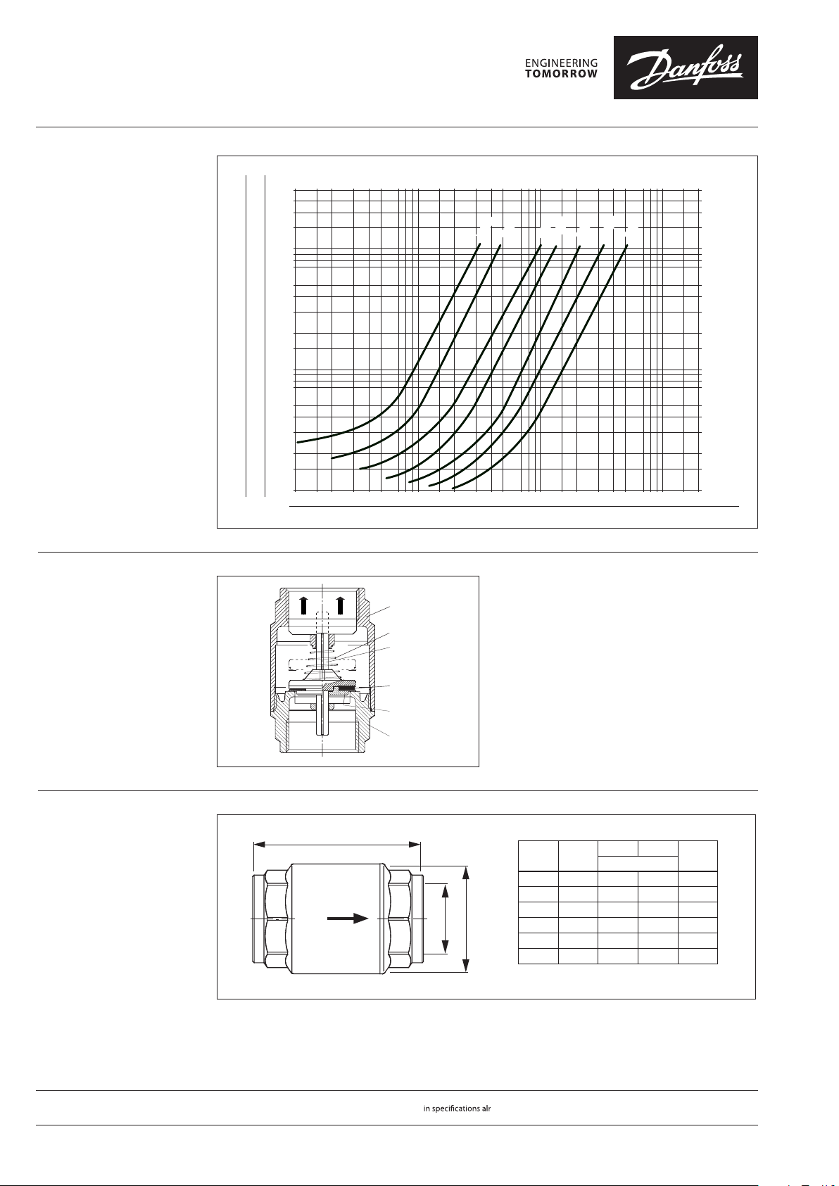
0.10.2 0.51 2510 20 50 100 200 mc/h
Flow diagram
2
200
1
100
0.5
0.2
0.1
mm H2O
20000
10000
50
5000
20
2000
10
1000
5
500
200
2
100
1
100 200 500 1000 2000 5000 10000 20000 50000 100000 200000 l/h
DN 10
DN 25
DN 32
DN 20
DN 15
DN 40
DN 50
Design
1. Threaded end
2. Washer
3. O-ring
4. Spindle
5. Spring
6. Body
Dimensions
⑥
⑤
④
③
②
①
L
D L
DN
G
D
G
(“)
15 ½ 32 58 150
20 ¾ 39 65 225
25 1 47 75 330
32 1 ¼ 60 80 545
40 1 ½ 67 86 685
50 2 83 94 1025
(mm)
Weight
(g)
oss can accept no responsibility for possible errors in catalogues, brochures and other printed material. Danfoss reserves the right to alter its products without notice. This also applies to products
vided that such alterations can be made without subsequential changes being necessary eady agreed.
2 | VD.BO.U1.02
tive companies. Danfoss and the Danfoss logotype are trademarks of Danfoss A/S. All rights reserved.
© Danfoss | DHS-SRMT/SI | 2018.01
 Loading...