

Page 1
C
PED 97/23/CE
Data sheet
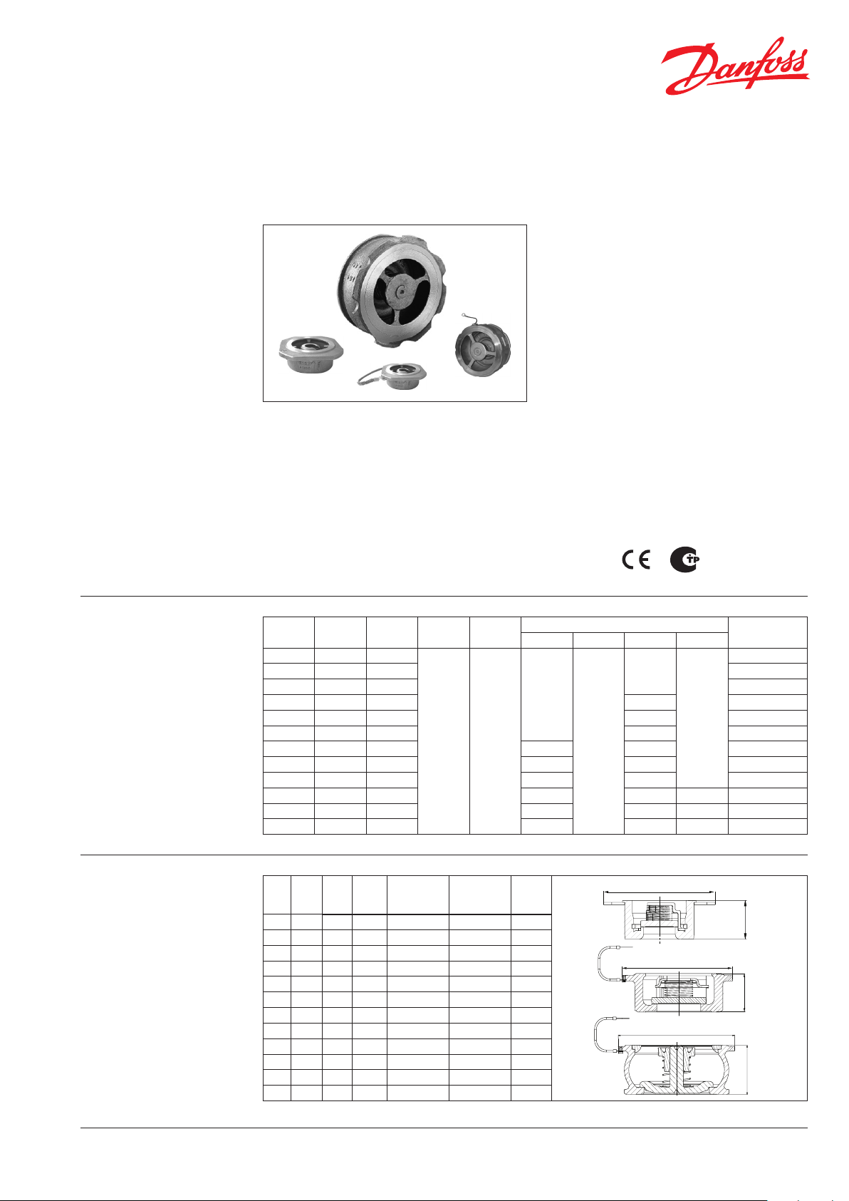
Non return Valve - Danfoss NVD 812
Description
Ordering
Note:
The indicated pressure for the
different categories of fluids
(L1/L2/G1/G2) is under no condition
a guarantee of use.
Therefore, it is essential to validate
the use of products under given
operating conditions.
• Using these check valves on networks
equipped with piston pumps or compressors
is not recommended.
Main Data:
• DN 15 - 200
• kVS 4,24 - 546 m3/h
• PN 25/40
• Medium:
- Circulation water, drinking water or chilled
glycolic water up to 50%
• Medium Temperature:
Features:
• Operates in any position
• Easy to install and dismantle, space-saving
• Minimum head loss
• Does not generate hammering
•
Closing system : disc with parabolic edges with
return spring ; lateral guiding by 3 or 4 ribs (DN
15 to 100).
•
Closing system with back axial guiding and
return spring (ND 125 to 200).
- 10 … 350°C
• Leakage rate according to EN12266-1 rate E
• International construction Standards:
- CE Conformity Directive 2014/68/EU
-
Connection acc. to ASA B16.1 class 125RF
- Connection according to ASA B16.5 class
150RF and 300RF
- Connection according to EN 1092.2
- Overall dimensions according to EN558-1
series 49
• Approvals:
• Metal/metal seal (machined trim)
˝
½ 15 4,24
¾ 20 7,8 0 065 B7531
1 25 12, 40 065B7532
1¼ 32 18 ,00 30 065B7533
1½ 40 28,00 25 065B7534
2 50 4 0,10 20 065B7535
2½ 65 72,50 30 15 0 65B7536
3 80 111,0 0 25 12 0 65B7537
4 10 0 182, 00 20 10 065B 7538
5 12 5 302,00 16 0,5 28 065 B7539
6 15 0 370, 00 13 0,5 23 065B7540
8 200 546,00 40 17 25
DN
Kv
(m3/h)
PN
40 40
PFA
(bar)
L1 L2 G1 G2
40
PS (bar)
40
40
40
Code No.
065B7530
065B7541
Dimensions
DEN-SMT/SI
ADNB
˝
½ 15 16 44
¾ 20 19 54
1 25 22 64
1¼ 32 28 78
1½ 40 31,5 88
2 50 40 98
2½ 65
3 80
4 100
5 12 5
6 150
8 200
VD.BO.P
(mm)
46 11 8 129 12 9 1,52
50 13 4 144 144 2,17
60 15 4 162 170 3,35
90 - 192 192 8,55
106 - 218 224 12,70
140 - - 284 30,00
2.02 © Danfoss 05/2019
C-PN6
(mm)
C - PN10/16/
ASA 150
(mm)
53 53
63 63
73 73
84 84
94 94
109 109
C - PN25/40/
ASA 300
(mm)
Weight
(kg)
0,10
0,14
0,23
0,35
0,52
0,73
B
C
B
C
B
1
Page 2
Data sheet Danfoss NVD 812
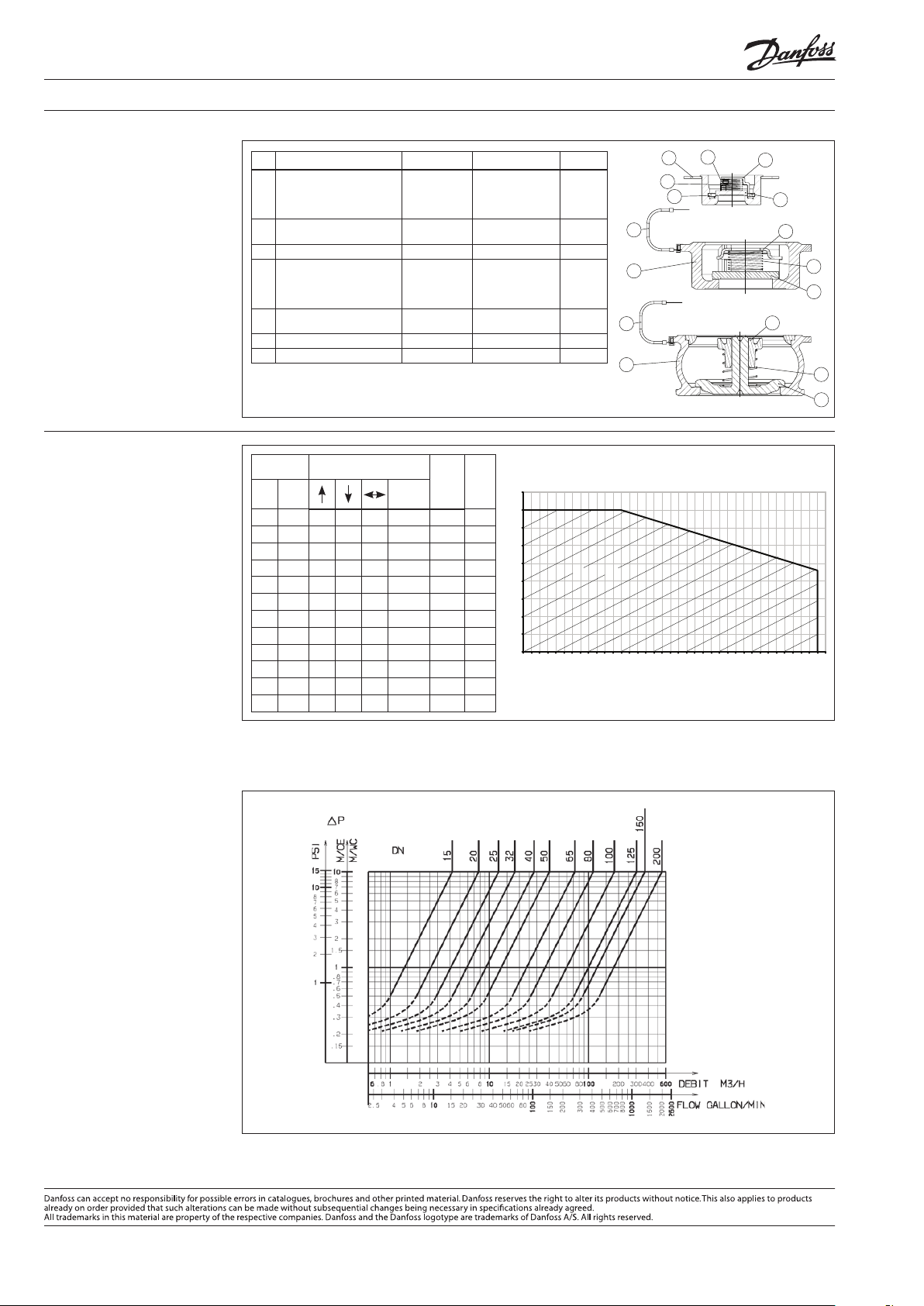
Design
Headloss diagram
Pos.
Description Material EURO ANSI
Casing DN15
DN20 to 65
1
DN80 to 100
DN125 to 200
Closing system DN15 to 100
2
DN125 to 200
Stainless steel
Stainless steel
X5Cr Ni18-10
GX 5CrN i19-10
GX 2CrN iMo19-11-2
GX 5CrN i19-10
X2 CrN iMo17 -12-2
GX 5CrN i19-10
AISI 304
AISI 304
AISI 316L
AISI 304
AISI 316L
AISI 304
3 Spring Stainless steel X10CrNi18- 8 AISI 302
Stop / Guide DN15
DN20 to 100
4
DN125 to 150
DN200
Centering collar DN15
5
Other DN
X5 CrN iMo17 -12-2
Stainless steel
X2C rNi18-9
GX 2CrN iMo19-11-2
GX 5CrN i19-10
Stainless steel X2C rNi18-9 AISI 304L
AISI 316L
AISI 304L
AISI 316L
AISI 304
6 Clips Stainless steel X10CrNi18- 8 AISI 302
7 Discharge anti-static braid Copper − −
DN
˝
½ 15 160
¾ 20
1 25
1¼ 32
1½ 40
2 50
2½ 65
3 80
4 100
5 125
6 150
8 200
Opening pressure
(mm)/WC
(mm)
Without
spring
120 140 20
165 125 145 20
165 115 140 25
190 130 160 30
200 120 160 40
210 110 155 50
210 100 155 55 72,50 5,3
226 95 16 0 65 111, 00 5,2
235 75 205 80 182,0 0 4,7
335 75 205 130 302,0 0 4,2
360 70 215 145 370,0 0 5,8
515 105 310 205
K
V
(m3/h)
4,24 4,4
7,8 0 4,1
12, 40 4,0
18,00 5,0
28,00 5 ,1
40 ,10 6,1
546,00
8,4
ζ
40
35
30
25
Pression (bar)
20
15
10
5
0
-10
WORKING AREA
0
50
3
5
4
1
6
7
1
2
4
3
2
7
1
4
3
2
100
150
200
250
300
350
Température (°C)
360
Direction for use :
• Solid line : Valve completely open
• Dotted line : opening stage of valve
Produce d b
2.02
2
VD.BO.P
y Danfoss A/S © 05/2019
 Loading...