

Page 1
Technical Information
MP1 Axial Piston Pumps
Size 28/32, 38/45
www.danfoss.com
Page 2

Technical Information
MP1 Axial Piston Pumps Size 28/32, 38/45
Revision history Table of revisions
Date Changed Rev
February 2022 Added option A3 endcap option to 38/45cc 0503
January 2022 Corrected the number of charge pressure in operating parameters 0502
December 2021 Added HDC control options 0501
April 2021 Corrected interface with ECU (EDC) graphic 0407
April 2020 Added model code option 0406
March 2020 Removed restricted model code options and changed document number from BC00000352 0405
January 2020 Added option A5 to system port type model code options 0303
November 2019 Fixed on P108935、P400313, P400325, 0302
October 2019 Updated with new control options 0301
March 2019 Updated with new control options 0201
May 2018 Add 14 tooth shaft, minor edits 0106
March 2018 Update MDC control illustrations 0105
January 2018 Add NFPE control 0104
October 2017 Minor edits 0103
April 2017 Minor edits 0102
August 2016 First Edition 0101
2 | © Danfoss | February 2022 BC178386485160en-000503
Page 3

Technical Information
MP1 Axial Piston Pumps Size 28/32, 38/45
Contents
General description
Overview..............................................................................................................................................................................................6
Features................................................................................................................................................................................................6
System diagram................................................................................................................................................................................ 7
Schematic............................................................................................................................................................................................8
Technical specifications
Design specifications...................................................................................................................................................................... 9
Technical data....................................................................................................................................................................................9
Operating parameters..................................................................................................................................................................10
Fluid specifications........................................................................................................................................................................10
Operation
High Pressure Relief Valve (HPRV) and charge checkHPRV and charge check........................................................11
Bypass function...............................................................................................................................................................................11
Charge Pressure Relief Valve (CPRV)CPRV function...........................................................................................................12
Loop flushing valve.......................................................................................................................................................................13
Electrical displacement control (EDC).................................................................................................................................... 13
EDC principle..............................................................................................................................................................................13
EDC operation............................................................................................................................................................................14
Control signal requirements, EDC MP1............................................................................................................................ 14
EDC solenoid data.................................................................................................................................................................... 15
Control response.......................................................................................................................................................................15
EDC response time..............................................................................................................................................................15
Manual override (MOR)...........................................................................................................................................................15
Hydraulic displacement control (HDC).................................................................................................................................. 17
HDC principle.............................................................................................................................................................................17
HDC operation...........................................................................................................................................................................17
Hydraulic signal pressure range..........................................................................................................................................18
Pump output flow direction vs. control pressure.........................................................................................................18
Control response.......................................................................................................................................................................18
Response time, HDC................................................................................................................................................................ 19
Swashplate angle sensor for EDC controls........................................................................................................................... 20
Swash plate angle sensor parameters (EDC).................................................................................................................. 20
Swash plate angle sensor connector.................................................................................................................................21
Interface with ECU (EDC)........................................................................................................................................................21
Manual displacement control....................................................................................................................................................21
MDC principle............................................................................................................................................................................ 21
MDC operation.......................................................................................................................................................................... 23
MDC shaft rotation...................................................................................................................................................................23
Control response.......................................................................................................................................................................24
MDC response time............................................................................................................................................................ 24
Neutral start switch (NSS)...................................................................................................................................................... 24
Case gauge port M14.............................................................................................................................................................. 25
Lever..............................................................................................................................................................................................25
Forward-neutral-reverse (FNR) electic control....................................................................................................................26
FNR principle..............................................................................................................................................................................26
Control response.......................................................................................................................................................................28
Response time, FNR............................................................................................................................................................28
Non feedback proportional electric control (NFPE).......................................................................................................... 28
Control signal requirements.................................................................................................................................................29
Control response.......................................................................................................................................................................30
Response time......................................................................................................................................................................31
Non-feedback, proportional hydraulic (NFPH) control....................................................................................................31
Control response.......................................................................................................................................................................32
Response time......................................................................................................................................................................32
Automotive control (AC)............................................................................................................................................................. 33
Control-cut-off valve (CCO valve).............................................................................................................................................35
CCO solenoid data....................................................................................................................................................................36
Brake gauge port with MDC................................................................................................................................................. 37
©
Danfoss | February 2022 BC178386485160en-000503 | 3
Page 4

Technical Information
MP1 Axial Piston Pumps Size 28/32, 38/45
Contents
Displacement limiter.....................................................................................................................................................................37
Displacement change (approximate)................................................................................................................................37
Speed sensor................................................................................................................................................................................... 38
Temperature range..................................................................................................................................................................38
Output pulses.............................................................................................................................................................................38
Mating connectors...................................................................................................................................................................38
Speed sensor 4.5 – 8 V technical data...............................................................................................................................38
Temperature sensor data............................................................................................................................................................39
Operating parameters
Input speed...................................................................................................................................................................................... 40
System pressure............................................................................................................................................................................. 40
Charge pressure..............................................................................................................................................................................41
Charge pump inlet pressure...................................................................................................................................................... 41
Case pressure...................................................................................................................................................................................41
Temperature.................................................................................................................................................................................... 41
Viscosity.............................................................................................................................................................................................42
System design parameters
Filtration system ............................................................................................................................................................................43
Filtration............................................................................................................................................................................................ 43
Suction filtration....................................................................................................................................................................... 43
Charge pressure filtration......................................................................................................................................................44
Independent braking system.................................................................................................................................................... 45
Fluid selection................................................................................................................................................................................. 45
Reservoir............................................................................................................................................................................................45
Case drain......................................................................................................................................................................................... 45
Charge pump...................................................................................................................................................................................45
Charge pump sizing/selection.............................................................................................................................................46
Charge pump output flow..........................................................................................................................................................47
Bearing life and external shaft loading.................................................................................................................................. 47
Hydraulic unit life...........................................................................................................................................................................49
Mounting flange loads.................................................................................................................................................................49
Shaft torques................................................................................................................................................................................... 51
Shaft selection........................................................................................................................................................................... 51
Shaft torque and splines lubrication................................................................................................................................. 51
Shaft torque for tapered shafts............................................................................................................................................51
Shaft availability and torque ratings.......................................................................................................................................52
Understanding and minimizing system noise.....................................................................................................................52
Sizing equations.............................................................................................................................................................................54
Model code
Model code (A - B - C)................................................................................................................................................................... 55
Model code (D)................................................................................................................................................................................56
Model code (F)................................................................................................................................................................................ 57
Model code (H - J - T).................................................................................................................................................................... 58
Model code (K)................................................................................................................................................................................ 59
Model code (E - M - N - Z - L)...................................................................................................................................................... 60
Model code (V - G - W)..................................................................................................................................................................61
Model code (X - Y)..........................................................................................................................................................................63
Installation drawings
28/32 ports....................................................................................................................................................................................... 64
38/45 ports....................................................................................................................................................................................... 65
28/32 dimensions...........................................................................................................................................................................66
28/32 dimensions with speed sensor.....................................................................................................................................68
38/45 dimensions...........................................................................................................................................................................69
38/45 dimensions with speed sensor.....................................................................................................................................72
Input shafts: option G4, F6 (SAE B, 13 teeth)........................................................................................................................73
Input shafts: option G1, F1 (SAE B, 14 teeth)........................................................................................................................74
Input shafts: option G5, F5 (SAE B, 15 teeth)........................................................................................................................75
4 | © Danfoss | February 2022 BC178386485160en-000503
Page 5

Technical Information
MP1 Axial Piston Pumps Size 28/32, 38/45
Contents
Input shafts: option A7, A9 (SAE B, straight key shaft)......................................................................................................76
Input shafts: option G6, G7 (SAE B, 19 teeth).......................................................................................................................77
Input shafts: option A6, A8 (SAE B, straight key shaft)......................................................................................................78
Input shafts: option F2, F3 (SAE B, taper key shaft) ...........................................................................................................79
Tapered shaft customer acknowledgement...................................................................................................................79
Auxiliary mounting: option A16, B16, C16, D16, E16, F16 (SAE A, 9 teeth)............................................................... 80
Auxiliary mounting: option A19, B19, C19, D19, E19, F19 (SAE A, 11 teeth).............................................................81
Auxiliary mounting: option A22, B22, C22, D22, E22, F22 (SAE B, 13 teeth)............................................................. 82
Auxiliary mounting: option A25, B25, C25, D25, E25, F25 (SAE B-B 15 teeth) .........................................................83
Controls
Electric displacement control (EDC)........................................................................................................................................84
Electric displacement control with CCO (EDC+CCO)........................................................................................................85
EDC with ASNSR........................................................................................................................................................................86
Hydraulic displacement control (HDC).................................................................................................................................. 87
Manual displacement control (MDC)......................................................................................................................................88
MDC with NSS option M2...................................................................................................................................................... 89
MDC with CCO options M3, M4...........................................................................................................................................90
MDC with NSS and CCO options M5, M6......................................................................................................................... 91
Forward-neutral-reverse (FNR)..................................................................................................................................................92
Non-feedback proportional electric (NFPE)......................................................................................................................... 93
Non-feedback proportional hydraulic (NFPH).....................................................................................................................94
Automotive control (AC)............................................................................................................................................................. 95
AC connectors dimensions................................................................................................................................................... 96
Filtration
Suction filtration: option S..........................................................................................................................................................97
Remote full flow charge pressure filtration: option R.......................................................................................................98
External full flow charge pressure filtration: option E.......................................................................................................99
©
Danfoss | February 2022 BC178386485160en-000503 | 5
Page 6

Technical Information
MP1 Axial Piston Pumps Size 28/32, 38/45
General description
MP1 overview
The MP1 pump is a variable displacement axial piston pump intended for closed circuit medium power
applications. The swashplate motion is controlled via compact hydraulic servo control system. A variety
of controls are available. These include mechanic or electric actuated feedback controls, electric or
hydraulic actuated non-feedback type controls, and a three-position electric control.. These controls
feature low hysteresis and responsive performance.
MP1 features
Designed for quality and reliability
•
Uniform design concept across frame sizes
•
Single piece housing to minimize leaks
•
Technologically advanced kit and servo system
•
Predictable, low friction swashplate bearing for precise machine control
Machine integration benefits
•
Industry leading pump length
•
Clean side for easier machine integration
•
Metric and Inch O-ring boss and Split flange (38/45 only) system port interfaces
•
Standard connection interfaces
Greater total efficiency
•
Increased pump efficiency
•
Lower control pressure for less power consumption
Control options
•
Electrical displacement control (EDC)
•
Manual displacement control (MDC)
•
Hydraulic displacement control (HDC)
•
Automotive control (AC-1, AC-2)
•
Forward-neutral-reverse (FNR)
•
Non-feedback proportional electric (NFPE)
•
Non-feedback proportional hydraulic (NFPH)
•
Common control across entire family
Expanded functionality
•
PLUS+1® Compliant control and options
•
Easy integration with Telematics
•
Integrated Flushing valve available
Modularity
•
Common control, charge pump and auxiliary pad options
•
Easy and quick conversion to the right configuration
6 | © Danfoss | February 2022 BC178386485160en-000503
Page 7
5
10
9
8
4
1
Fixed
Displacement
Motor
MP1
Axial Piston
Pump
7
6
2
3
P400327
Technical Information
MP1 Axial Piston Pumps Size 28/32, 38/45
General description
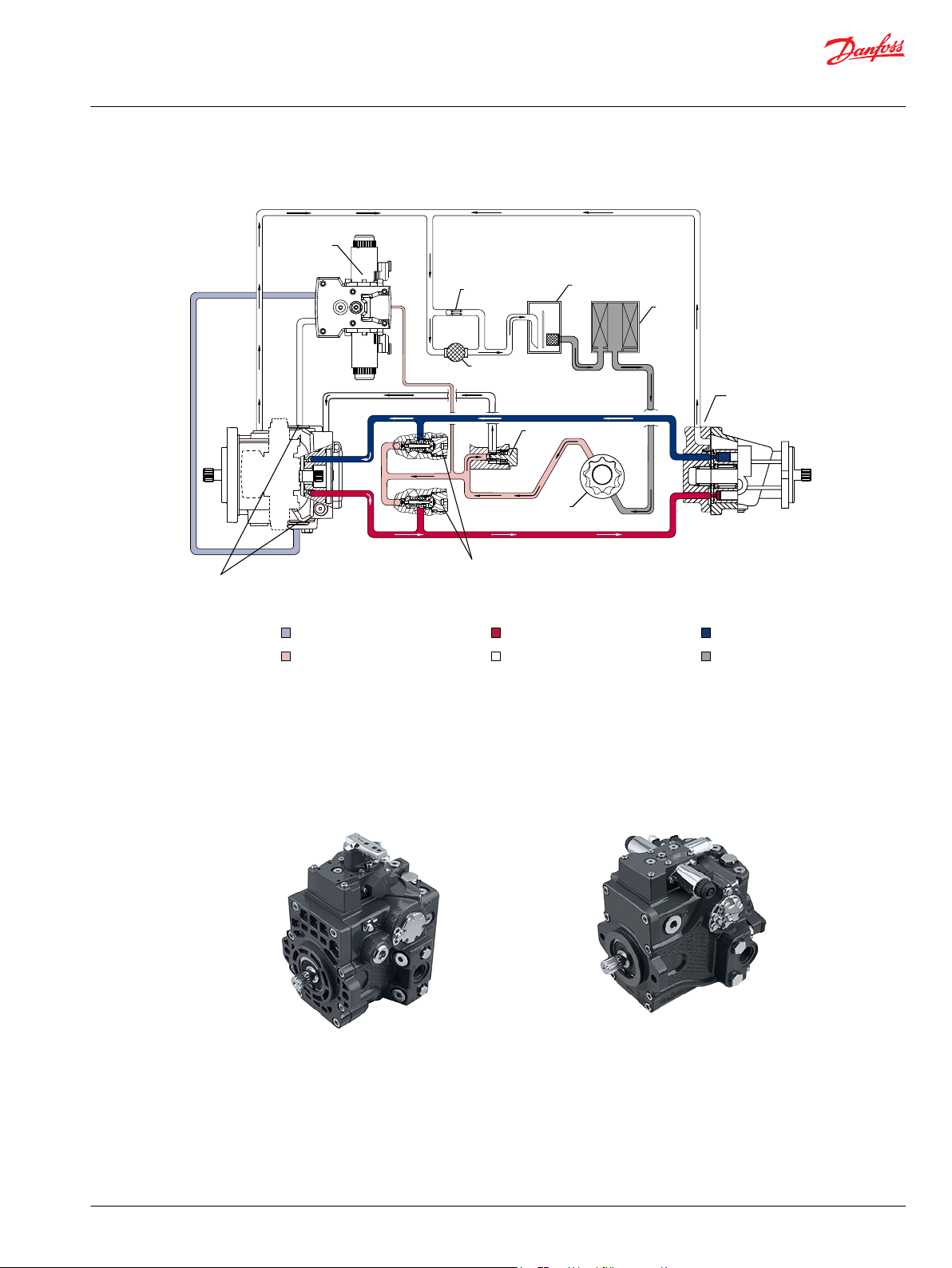
MP1 system diagram
Servo Pressure System High Pressure System Low Pressure
Charge Pressure Case Flow Suction Flow
1. Control 2. Heat Exchanger 3. Heat Exchanger Bypass
4. Reservoir 5. Filter 6. Servo Piston
7. Check Valves with High Pressure
Relief Valves
10. Case Drain
8. Charge Relief Valve 9. Charge Pump
MP1 28/32 MP1 38/45
©
Danfoss | February 2022 BC178386485160en-000503 | 7
Page 8
M14
C1
C2
EDC with CCO
EDC
MDC with NSS
Suction
filtration
Remote
filtration
E F
E
M3 for 28/32
M3 for 38/45
F L2
A
MA
MB
B
L1S
M4M5
Check
Relief
with
Bypass
Loop Flushing
X7M14
C2C1
M14
C1 C2
FNR
M14
AM3
MDC
M14
M14
NFPE
C2
C1
X1 M14 X2
HDC
Technical Information
MP1 Axial Piston Pumps Size 28/32, 38/45
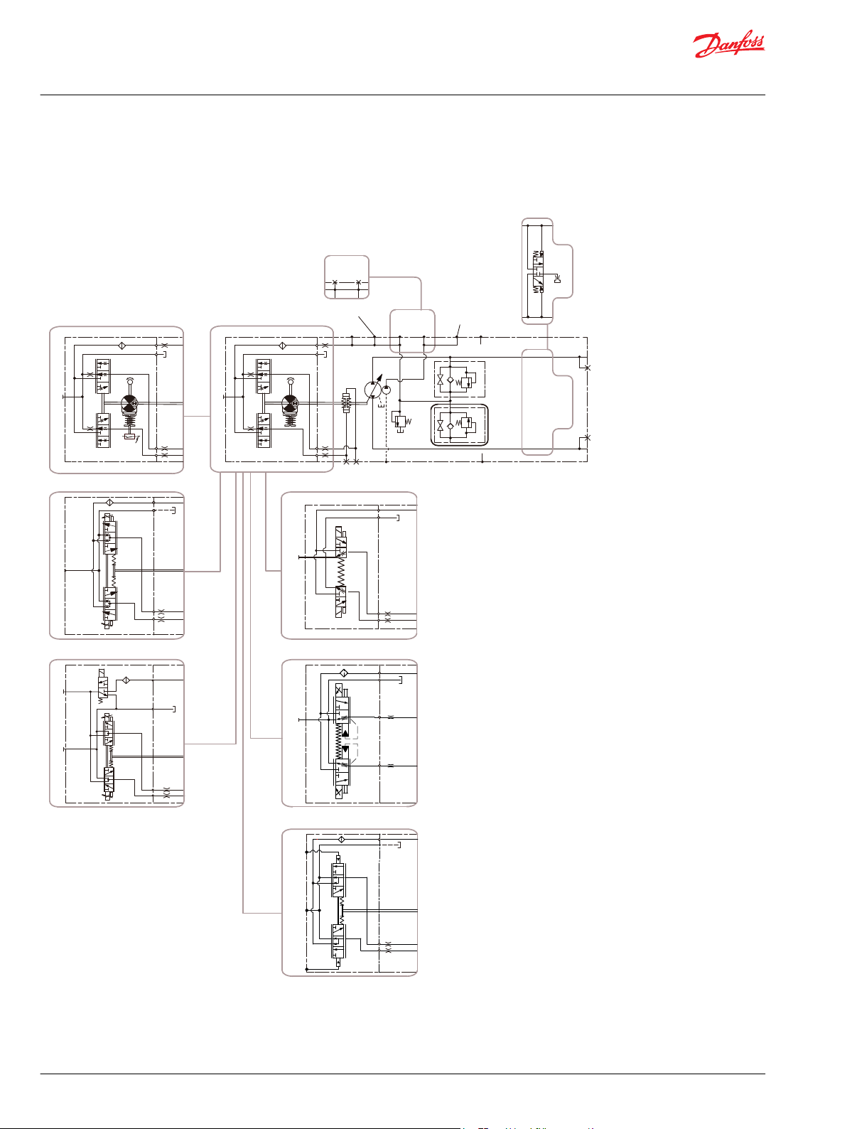
General description
MP1 schematic
8 | © Danfoss | February 2022 BC178386485160en-000503
Page 9
Technical Information
MP1 Axial Piston Pumps Size 28/32, 38/45
Technical specifications
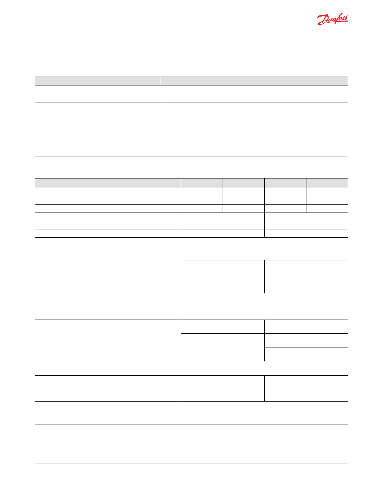
MP1 design specifications
Features MP1
Design Axial piston pump with variable displacement using compact servo piston control.
Direction of input rotation Clockwise or counterclockwise
Pump installation position is discretionary, however the recommended control position is
on the top or at the side with the top position preferred. If the pump is installed with the
control at the bottom, flushing flow must be provided through port M14 located on the
Recommended installation position
Filtration configuration Suction or charge pressure filtration
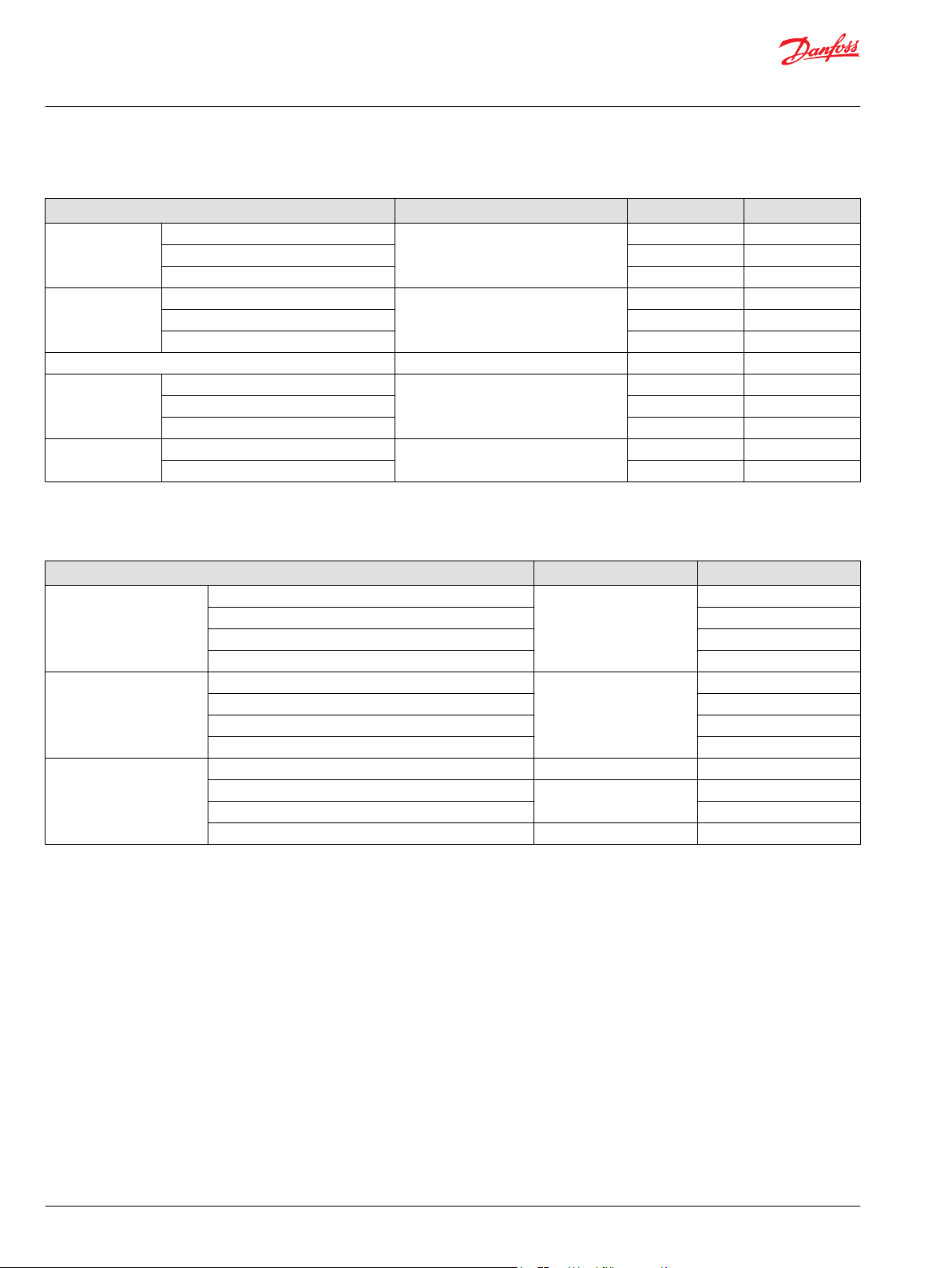
MP1 technical data
Feature 28 32 38 45
Displacement (cm3/rev [in3/rev]) 28.0 [1.71] 31.8 [1.94] 38.0 [2.32] 45.1 [2.75]
Flow at rated (continuous) speed (l/min [US gal/min]) 95.3 [25.2] 108.1 [28.5] 125.3 [33.1] 149.5 [39.5]
Torque at maximum displacement (N•m/bar [lbf•in/1000psi]) 0.45 [272.0] 0.51 [308.9] 0.60 [369.1] 0.72 [438.1]
Mass moment of inertia of rotating components (kg•m2 [slug•ft2]) 0.0020 [0.0015] 0.0030 [0.0022]
Mass (kg [lb]) 29.6 [65.3] 38 [83.8]
Oil volume (liter [US gal]) 1.5 [0.40] 2.0 [0.53]
Mounting flange ISO 3019-1 flange 101-2 (SAE B)
Input shaft outer diameter, splines and tapered shafts ISO 3019-1, outer Ø22mm - 4 (SAE B, 13 teeth)
Auxiliary mounting flange with metric fasteners, shaft outer diameter
and splines
Main port configuration A, B
Case drain ports L1, L2
Suction ports S
Other ports ISO 11926-1, (Inch O-ring boss)
Customer interface threads Metric fasteners
EDC, HDC, FNR, NFPE, NFPH, AC-1, AC-2 and MDC control. Vertical input shaft installation is
acceptable. The housing must always be filled with hydraulic fluid. Recommended
mounting for a multiple pump stack is to arrange the highest power flow towards the
input source. Consult Danfoss for non-conformance to these guidelines.
ISO 3019-1, outer Ø25mm - 4 (SAE B-B, 15 teeth)
ISO 3019-1, outer Ø31mm - 4 (19 teeth)
ISO 3019-1, outer Ø22mm - 1 (Straight
Key)
ISO 3019-1, flange 82-2, outer Ø16mm - 4 (SAE A, 9 teeth)
ISO 3019-1, flange 82-2, outer Ø19mm - 4 (SAE A, 11 teeth)
ISO 3019-1, flange 101-2, outer Ø22mm - 4 (SAE B, 13 teeth)
ISO 3019-1, flange 101-2, outer Ø25mm - 4 (SAE B-B, 15 teeth)
ISO 11926-1 - 1 1/16 - 12 (Inch O-ring
boss)
ISO 6149-1, M27x2 (Metric o-ring boss)
ISO 11926-1, 1 1/16 -12 (Inch O-ring boss)
ISO 6149-1, M27x2 (Metric O-ring boss)
ISO 11926-1 - 1 1/16-12 (Inch O-ring
boss)
ISO 6149-1 - M27x2 (Metric O-ring
boss)
ISO 6149 -1, (Metric O-ring boss)
ISO 3019-1, outer Ø25mm - 4 (Straight
Key)
ISO 3019-1, outer Ø25mm -3 (Conical
keyed, taper 1:8)
ISO 11926-1 - 1 5/16 - 12 (Inch O-ring
boss)
ISO 6162, Ø19mm, (Split flange boss,
M10x1.5)
ISO 6149-1 - M33x2 (Metric O-ring
boss)
ISO 11926-1 - 1 5/16-12 (Inch O-ring
boss)
ISO 6149-1 - M33x2 (Metric O-ring
boss)
©
Danfoss | February 2022 BC178386485160en-000503 | 9
Page 10
Technical Information
MP1 Axial Piston Pumps Size 28/32, 38/45
Technical specifications
MP1 operating parameters
Features Units 28/32 38/45
Input speed Minimum
Rated 3400 3300
Maximum 4000 3900
System pressure Maximum working pressure bar [psi] 350 [5000] 350 [5000]
Maximum pressure 380 [5429] 380 [5429]
Minimum low loop (above case) 10 [143] 10 [143]
Charge pressure (minimum) bar [psi] 16 [232] 16 [232]
Charge pump inlet
pressure
Minimum (continuous) bar (absolute) [in Hg vacuum] 0.8 [6] 0.8 [6]
Minimum (cold start) 0.2 [24] 0.2 [24]
Maximum 2.0 2.0
Case pressure Rated bar [psi] 3 [43] 3 [43]
Maximum 5 [71] 5 [71]
1
No load condition. Refer to System Design Parameters/Charge Pump for details.
1
min-1 (rpm) 500 500
MP1 fluid specifications
Features Units 28/32/38/45
Viscosity Intermittent
Minimum 7 [49]
Recommended range 12 - 80 [66 - 370]
Maximum (cold start)
Temperature range
3
Minimum (cold start) °C [°F] -40 [-40]
Recommended range 60 - 85 [140 - 185]
Maximum continuous 104 [220]
Maximum intermittent 115 [240]
Filtration (recommended
minimum)
Cleanliness per ISO 4406 22/18/13
Efficiency (charge pressure filtration) β-ratio β15-20=75(β10≥10)
Efficiency (suction filtration) β35-45=75(β10≥2)
Recommended inlet screen mesh size µm 100 - 125
1
Intermittent=Short term t <1 min per incident and not exceeding 2 % of duty cycle based load-life.
2
Cold start = Short term t < 3 min, p < 50 bar [725 psi], n < 1000 min-1 (rpm)
3
At the hottest point, normally case drain port.
1
2
mm2/sec. [ SUS] 5 [42]
1600 [7500]
10 | © Danfoss | February 2022 BC178386485160en-000503
Page 11
P400353
High Pressure
Low Pressure
Technical Information
MP1 Axial Piston Pumps Size 28/32, 38/45
Operation
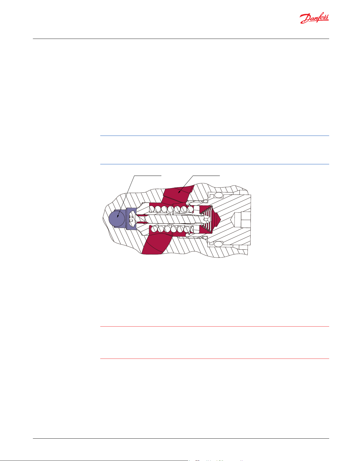
MP1 high pressure relief valve (HPRV) and charge check
All MP1 pumps are equipped with a combination high pressure relief and charge check valve. The highpressure relief function is a dissipative (with heat generation) pressure control valve for the purpose of
limiting excessive system pressures. The charge check function acts to replenish the low-pressure side of
the working loop with charge oil. Each side of the transmission loop has a dedicated HPRV valve that is
non-adjustable with a factory set pressure. When system pressure exceeds the factory setting of the
valve, oil is passed from the high pressure system loop, into the charge gallery, and into the low pressure
system loop via the charge check.
The pump order code allows for different pressure settings to be used at each system port. The system
pressure order code for pumps with only HPRV is a reflection of the HPRV setting.
HPRV´s are factory set at a low flow condition. Any application or operating condition which leads to
elevated HPRV flow will cause a pressure rise with flow above a valve setting. Consult factory for
application review. Excessive operation of the HPRV will generate heat in the closed loop and may cause
damage to the internal components of the pump.
Bypass function
The bypass function allows a machine or load to be moved without rotating the pump shaft or prime
mover. The single pump HPRV valve also provides a loop bypass function when each of the two HPRV hex
plugs are mechanically backed out three full turns.
Engaging the bypass function mechanically connects both A & B sides of the working loop to the
common charge gallery.
Possible damage to hydromotor(s).
Excessive speeds and extended load/vehicle movement must be avoided. The load or vehicle should be
moved not more than 20% of maximum speed and for a duration not exceeding 3 minutes. When the
bypass function is no longer needed, care should be taken to re-seat the HPRV hex plugs to the normal
operating position.
©
Danfoss | February 2022 BC178386485160en-000503 | 11
Page 12
Charge Pressure
Case Drain
P400341
Technical Information
MP1 Axial Piston Pumps Size 28/32, 38/45
Operation
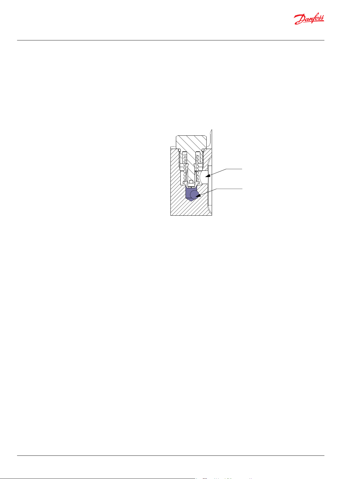
MP1 charge pressure relief valve (CPRV) function
An internal charge pressure relief valve (CPRV) regulates charge pressure within the hydraulic circuit. The
CPRV is a direct acting poppet valve that regulates charge pressure at a designated level above case
pressure.
The charge pressure relief valve setting is specified within the model code of the pump. MP1 pumps with
charge pump have the CPRV set at 1800 rpm while MP1 pumps without charge pump have the CPRV set
with 18.9 l/min [5.0 US gal/min] of external supply flow. The charge pressure rise rate, with flow, is
approximately 1 bar/10 liter [5.4 psi/US gal].
12 | © Danfoss | February 2022 BC178386485160en-000503
Page 13
P003 191
Feedback from
Swash plate
PTF00B
M14
C1 C2
F00A
P003 478E
Technical Information
MP1 Axial Piston Pumps Size 28/32, 38/45
Operation
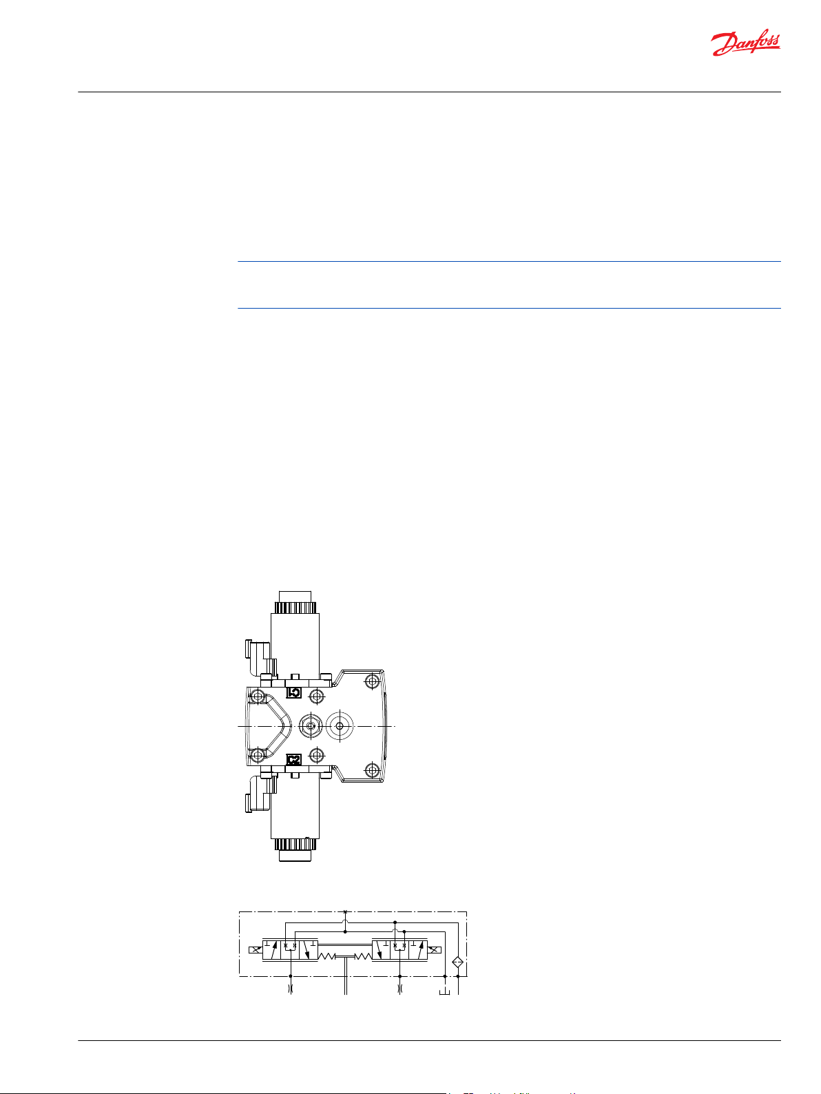
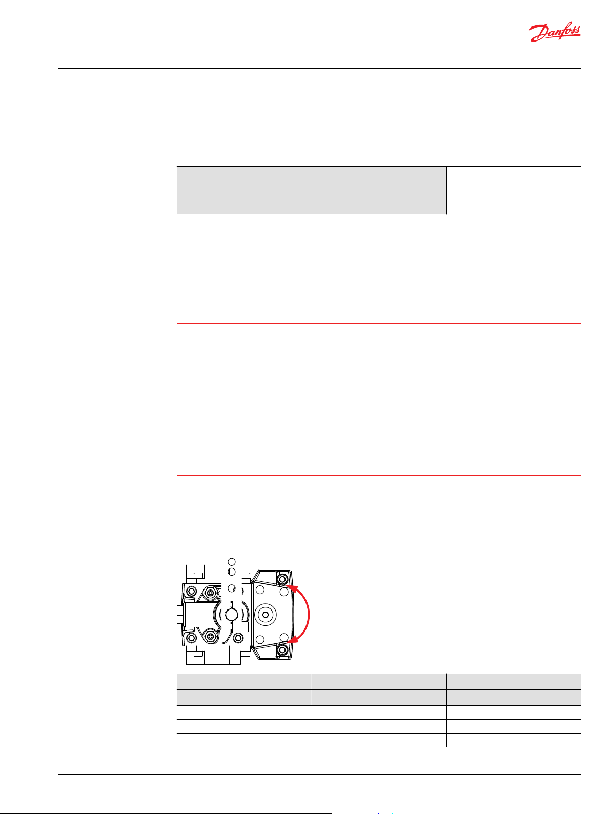
Loop flushing valve
MP1 pumps are available with an optional integral loop flushing. A loop flushing valve will remove heat
and contaminants from the main loop at a rate faster than otherwise possible.
The MP1 loop flushing design is a simple spring centered shuttle spool with an orifice plug. The shuttle
shifts at approximately . The flushing flow is a function of the low loop system pressure (charge) and the
size of the plug.
When a MP1 pump is used with an external loop flushing shuttle valve, ensure that the charge setting of
the pump matches the setting of the loop flushing shuttle valve. Contact your Danfoss representative for
the availability of additional charge relief settings.
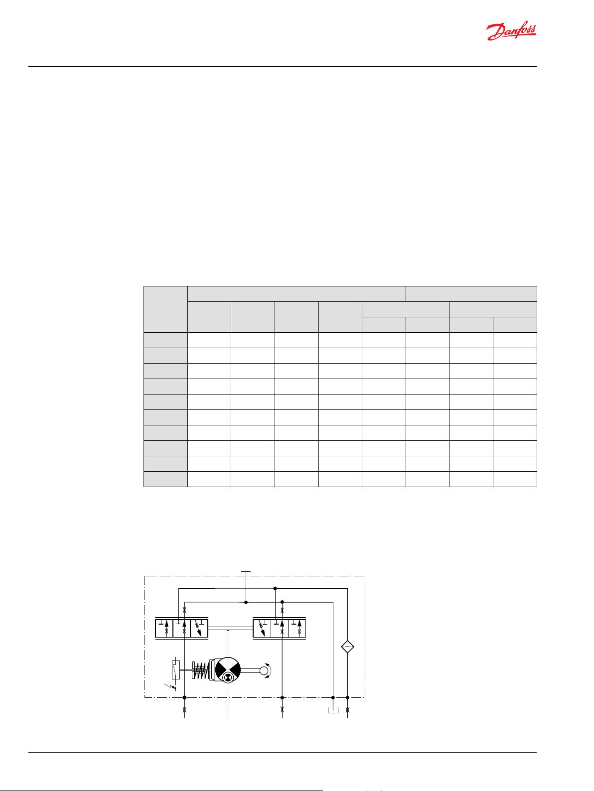
Electrical displacement control (EDC)
EDC principle
An EDC is a displacement (flow) control. Pump swashplate position is proportional to the input command
and therefore vehicle or load speed (excluding influence of efficiency), is dependent only on the prime
mover speed or motor displacement.
The Electrical Displacement Control (EDC) consists of a pair of proportional solenoids on each side of a
three-position, four-way porting spool. The proportional solenoid applies a force input to the spool,
which ports hydraulic pressure to either side of a double acting servo piston. Differential pressure across
the servo piston rotates the swashplate, changing the pump‘s displacement from full displacement in
one direction to full displacement in the opposite direction. Under some circumstances, such as
contamination, the control spool could stick and cause the pump to stay at some displacement.
A 170 μm screen is located in the supply line immediately before the control porting spool.
EDC control
©
Danfoss | February 2022 BC178386485160en-000503 | 13
EDC schematic
Page 14
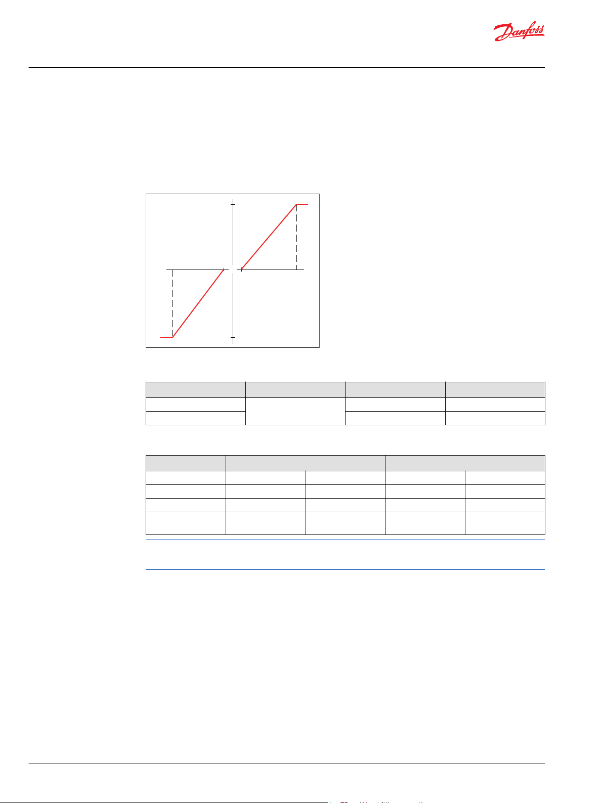
"0"
-b -a
ba
100 %
100 %
Displacement
Current mA
Technical Information
MP1 Axial Piston Pumps Size 28/32, 38/45
Operation
EDC operation
EDC’s are current driven controls requiring a Pulse Width Modulated (PWM) signal. Pulse width
modulation allows more precise control of current to the solenoids. The PWM signal causes the solenoid
pin to push against the porting spool, which pressurizes one end of the servo piston, while draining the
other. Pressure differential across the servo piston moves the swashplate.
A swashplate feedback link, opposing control links, and a linear spring provide swashplate position force
feedback to the solenoid. The control system reaches equilibrium when the position of the swashplate
spring feedback force exactly balances the input command solenoid force from the operator. As
hydraulic pressures in the operating loop change with load, the control assembly and servo/swashplate
system work constantly to maintain the commanded position of the swashplate.
The EDC incorporates a positive neutral deadband as a result of the control spool porting, preloads from
the servo piston assembly, and the linear control spring. Once the neutral threshold current is reached,
the swashplate is positioned directly proportional to the control current. To minimize the effect of the
control neutral deadband, we recommend the transmission controller or operator input device
incorporate a jump up current to offset a portion of the neutral deadband.
The neutral position of the control spool does provide a positive preload pressure to each end of the
servo piston assembly.
When the control input signal is either lost or removed, or if there is a loss of charge pressure, the springloaded servo piston will automatically return the pump to the neutral position.
Control signal requirements, EDC MP1
Pump displacement vs. control current
EDC control current
Voltage 12 V
Minimum current to stroke pump a
Pin connections any order
*
Factory test current, for vehicle movement or application actuation expect higher or lower value.
*
b 1640 mA 820 mA
DC
640 mA 330 mA
24 V
DC
14 | © Danfoss | February 2022 BC178386485160en-000503
Page 15
Technical Information
MP1 Axial Piston Pumps Size 28/32, 38/45
Operation
EDC solenoid data
Description 12 V 24 V
Maximum current 1800 mA 920 mA
Nominal coil resistance @ 20 °C [68 °F] 3.66 Ω 14.20 Ω
Inductance 33 mH 140 mH
PWM signal frequency Range 70 – 200 Hz
IP Rating IEC 60 529 IP 67
Connector color Black
*
PWM signal required for optimum control performance.
Pump output flow direction vs. control signal
Shaft rotation CW CCW
Coil energized
Port A out in in out
Port B in out out in
Servo port pressurized M4 M5 M4 M5
*
For coil location see Installation drawings.
*
@ 80 °C [176 °F] 4.52 Ω 17.52 Ω
Recommended
DIN 40 050, part 9 IP 69K with mating connector
*
100 Hz
C1 C2 C1 C2
Control response
MP1 controls are available with optional control passage orifices to assist in matching the rate of swashplate response to the application requirements (e.g. in the event of electrical failure).
The time required for the pump output flow to change from zero to full flow (acceleration) or full flow to
zero (deceleration) is a net function of spool porting, orifices, and charge pressure.
A swash-plate response times table is available for each frame size. Testing should be conducted to verify
the proper orifice selection for the desired response. Typical response times at the following conditions:
Δ p = 250 bar [3626 psi]
Charge pressure = 20 bar [290 psi]
Viscosity and temperature = 30 mm²/s [141 SUS] and 50 °C [122 °F]
Speed = 1800 min-1 (rpm)
MP1 EDC response time
Stroking direction 0.8 mm [0.03 in]
orifice
28/32 38/45 28/32 38/45 28/32 38/45 28/32 38/45
Neutral to full flow 1.3 s 2.1 s 0.9 s 1.3 s 0.6 s 0.9 s 0.4 s 0.6 s
Full flow to neutral 1.0 s 1.5 s 0.7 s 0.9 s 0.4 s 0.6 s 0.2 s 0.3 s
1.0 mm [0.04 in]
orifice
1.3 mm [0.05 in]
orifice
No orifice
Manual override (MOR)
Initial actuation of the o-ring seal MOR plunger will require a force of 45 N. Additional actuations typically
require less force to engage the MOR plunger. Proportional control of the pump via the MOR is not
intended. The MOR plunger has a 4 mm diameter and must be manually depressed to be engaged.
Depressing the plunger mechanically moves the control spool which allows the pump to go on stroke.
©
Danfoss | February 2022 BC178386485160en-000503 | 15
Page 16
P003 204
Technical Information
MP1 Axial Piston Pumps Size 28/32, 38/45
Operation
Unintended MOR operation can cause the pump to go into stroke.
The vehicle or device must always be in a safe condition (example: vehicle lifted off the ground) when
using the MOR function. The MOR should be engaged anticipating a full stroke response from the pump.
Refer to control flow table for the relationship of solenoid to direction of flow.
MOR and schematic
16 | © Danfoss | February 2022 BC178386485160en-000503
Page 17
P400520
P400519
X1
F00B
F00A
Feedback from
Swashplate
T P
X2M14
Technical Information
MP1 Axial Piston Pumps Size 28/32, 38/45
Operation
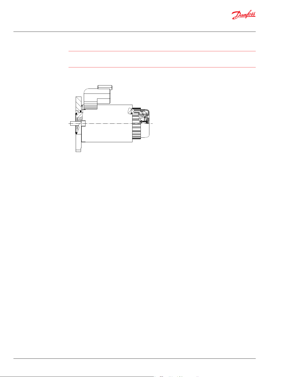
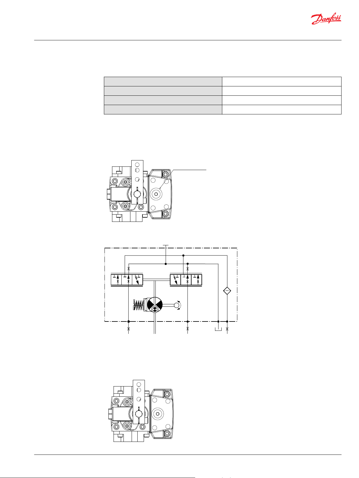
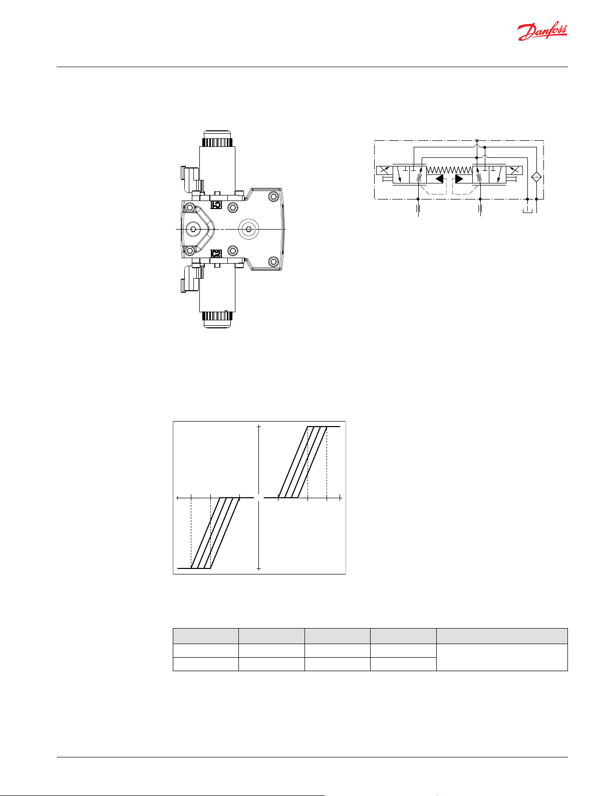
Hydraulic displacement control (HDC)
HDC principle
An HDC is a Hydraulic Displacement Control. Pump swashplate position is proportional to the input
command and therefore vehicle speed or load speed (excluding influence of efficiency), is dependent
only on the prime mover speed or motor displacement.
The HDC control uses a hydraulic input signal to operate a porting spool, which ports hydraulic pressure
to either side of a double acting servo piston. The hydraulic signal applies a force input to the spool
which ports hydraulic pressure to either side of a double acting servo piston. Differential pressure across
the servo piston rotates the swashplate, changing the pump’s displacement from full displacement in
one direction to full displacement in the opposite direction. Under some circumstances, such as
contamination, the porting spool could stick and cause the pump to stay at some displacement.
A serviceable 175 μm screen is located in the supply line immediately before the control porting spool.
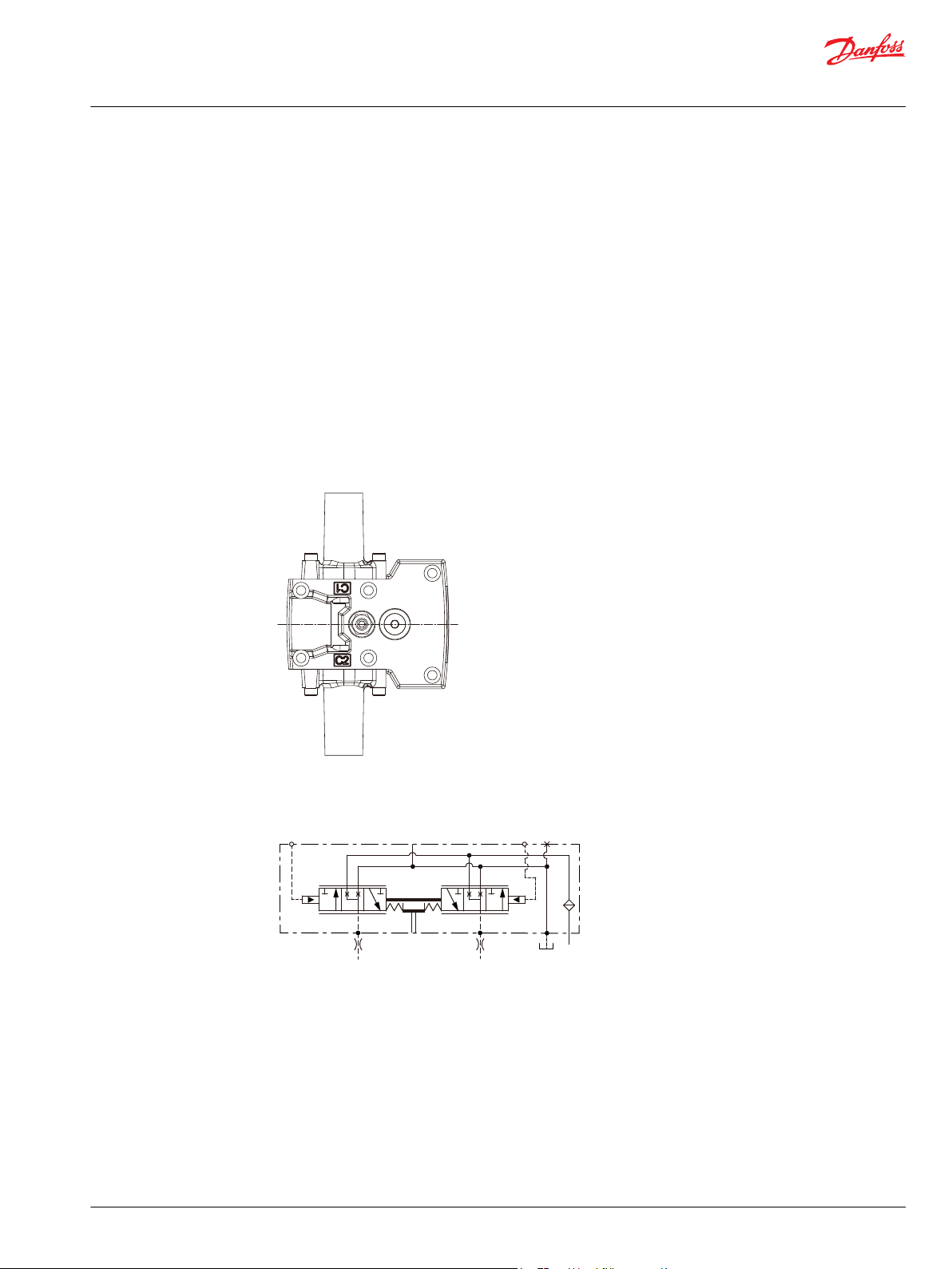
HDC control
HDC schematic
HDC operation
HDC’s are hydraulically driven control which ports hydraulic pressure to either side of a porting spool,
which pressurizes one end of the servo piston, while draining the other end to case. Pressure differential
across the servo piston moves the swashplate.
A swashplate feedback link, opposing control linkage, and a linear spring provide swashplate position
force feedback to the hydraulic pressure. As hydraulic pressures in the operating loop change with load,
the control assembly and servo/swashplate system work constantly to maintain the commanded position
of the swashplate.
©
Danfoss | February 2022 BC178386485160en-000503 | 17
Page 18
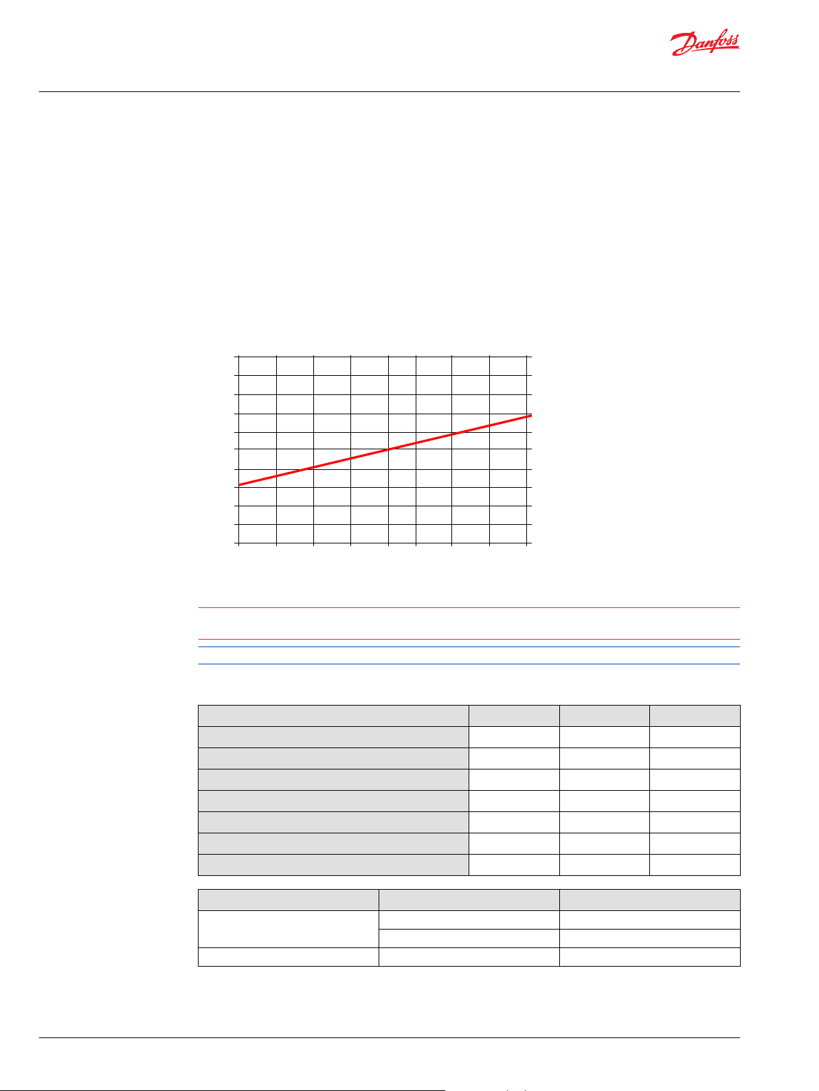
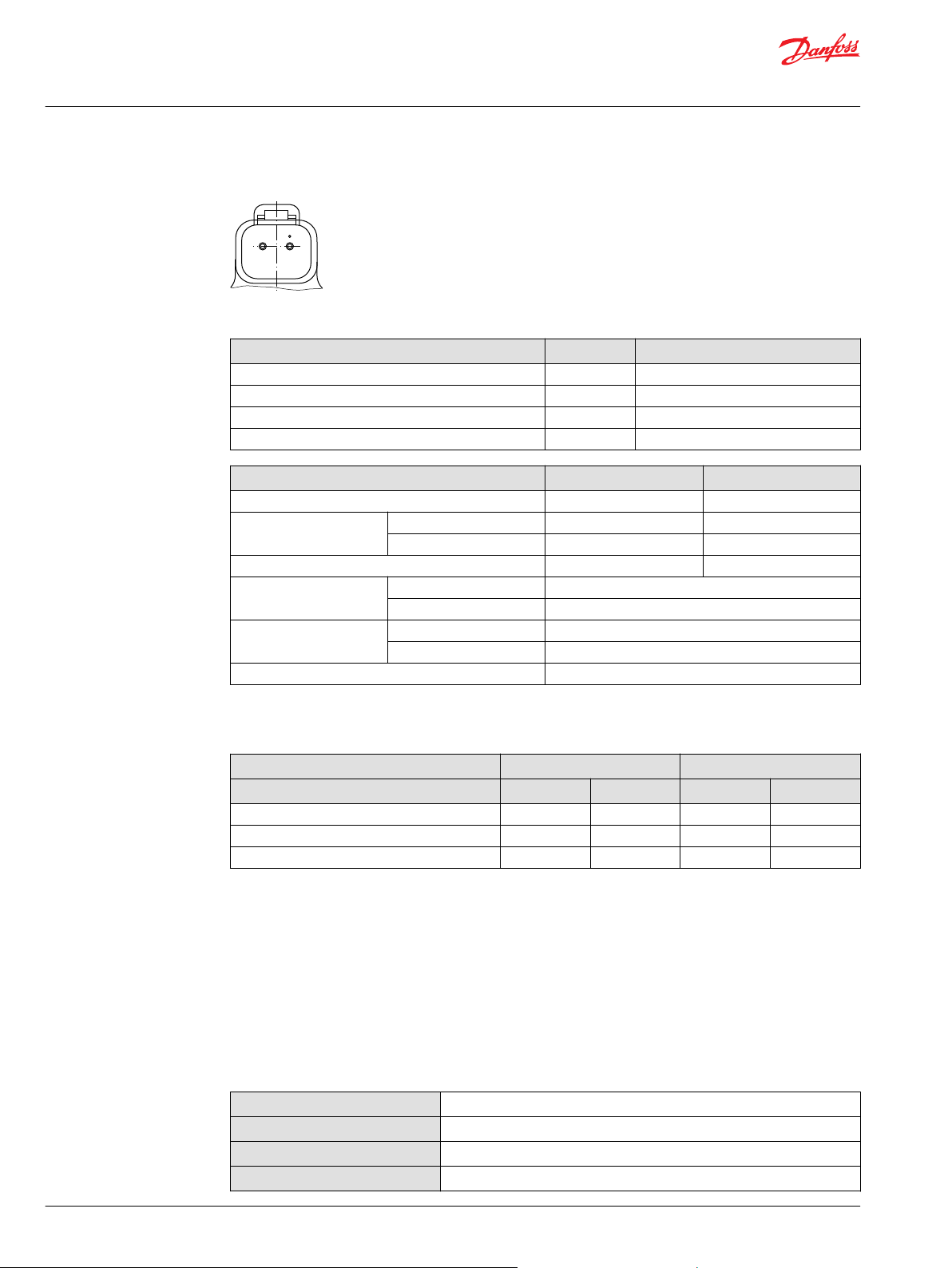
"0"
Signal pressure
Displacement
100 %
a b
-b -a
100 %
P102 031E
Technical Information
MP1 Axial Piston Pumps Size 28/32, 38/45
Operation
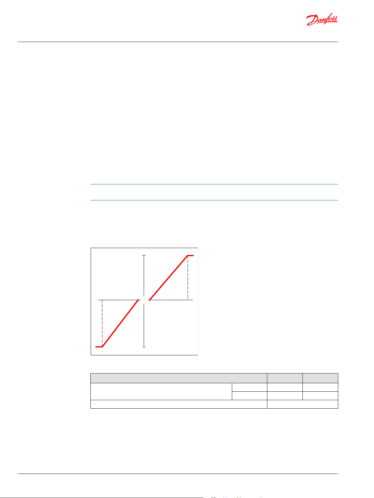
The HDC incorporates a positive neutral dead band as a result of the control spool porting, preloads from
the servo piston assembly, and the linear control spring. Once the neutral threshold point is reached, the
swashplate is positioned directly proportional to the control pressure.
When the control input is either lost or removed, or if there is a loss of charge pressure, the spring loaded
servo piston will automatically return the pump to the neutral position.
Pump displacement vs signal pressure
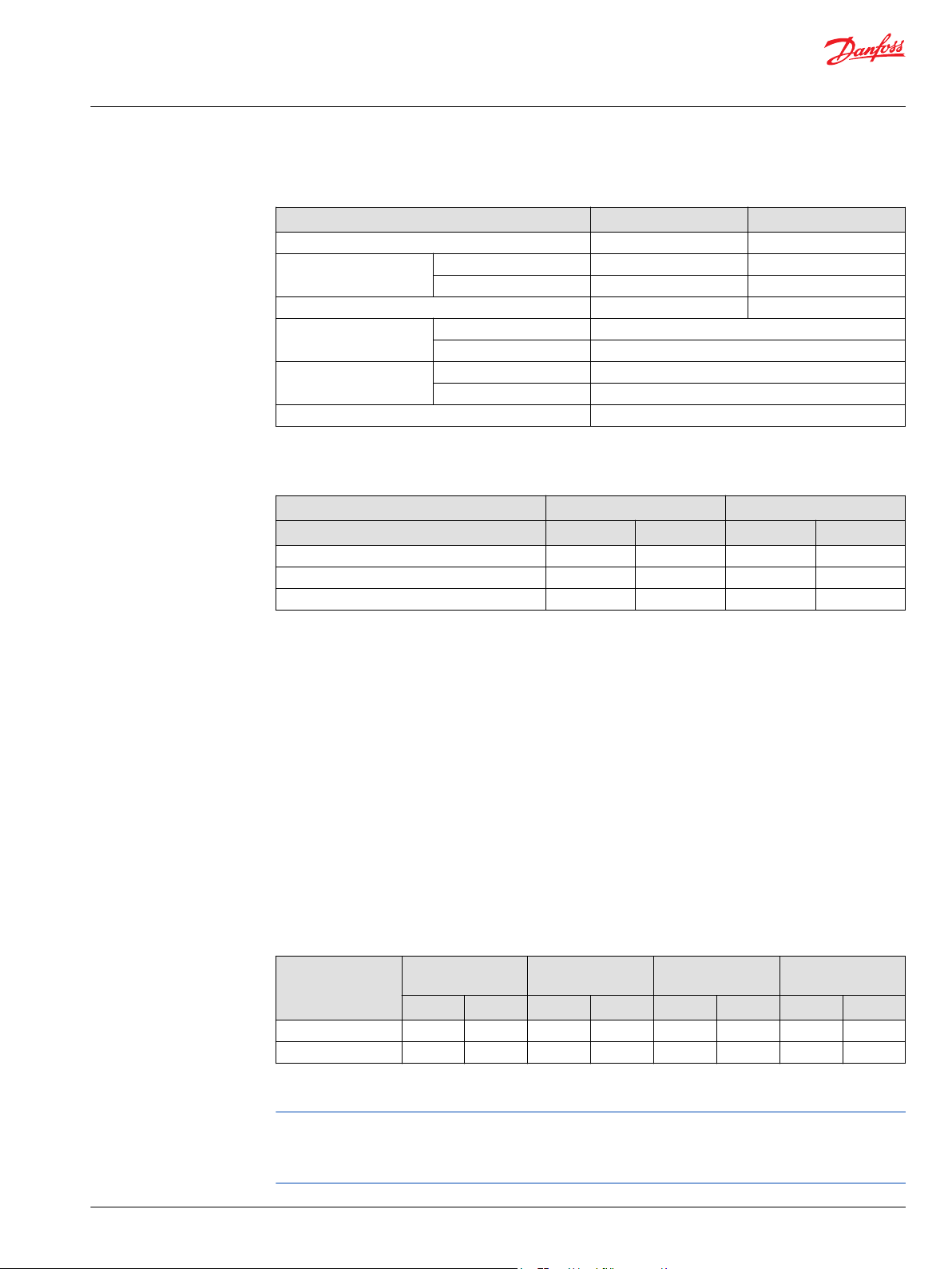
Hydraulic signal pressure range
Type Unit Start of control End of control
Option bar 3.0 11.6
Standard 4.2 16.2
Pump output flow direction vs. control pressure
Shaft rotation HDC Clockwise (CW) seen from shaft Counter Clockwise (CCW) seen from shaft
Port energized X1 X2 X1 X2
Port A Out (high) In (low) In (low) Out (high)
Port B In (low) Out (high) Out (high) In (low)
Servo port high
pressure
M4 M5 M4 M5
For appropriate performance of HDC characteristic, keep the drain pressure of pilot valve to be equal or
slightly higher than pump case pressure.
Control response
MP1 controls are available with optional control passage orifices to assist in matching the rate of swashplate response to the application requirements (e.g. in the event of electrical failure).
The time required for the pump output flow to change from zero to full flow (acceleration) or full flow to
zero (deceleration) is a net function of spool porting, orifices, and charge pressure.
A swash-plate response times table is available for each frame size. Testing should be conducted to verify
the proper orifice selection for the desired response. Typical response times at the following conditions:
Δ p = 250 bar [3626 psi]
Charge pressure = 20 bar [290 psi]
Viscosity and temperature = 30 mm²/s [141 SUS] and 50 °C [122 °F]
Speed = 1800 min-1 (rpm)
18 | © Danfoss | February 2022 BC178386485160en-000503
Page 19

Technical Information
MP1 Axial Piston Pumps Size 28/32, 38/45
Operation
Response time, HDC
Stroking
direction
Neutral to
full flow
Full flow to
neutral
0.8 mm [0.03 in] orifice 1.0 mm [0.04 in] orifice 1.3 mm [0.05 in] orifice No orifice
28/32 38/45 28/32 38/45 28/32 38/45 28/32 38/45
1.3 s 2.1 s 0.9 s 1.3 s 0.6 s 0.9 s 0.3 s 0.6 s
1.0 s 1.5 s 0.7 s 0.9 s 0.4 s 0.6 s 0.2 s 0.3 s
©
Danfoss | February 2022 BC178386485160en-000503 | 19
Page 20
-18° -13° -8°
100%
90%
80%
70%
60%
50%
40%
30%
20%
10%
0%
Swashplate angle
Sensor output, % of supply voltage
-3° 0° 2° 7° 12° 17°
W
Technical Information
MP1 Axial Piston Pumps Size 28/32, 38/45
Operation
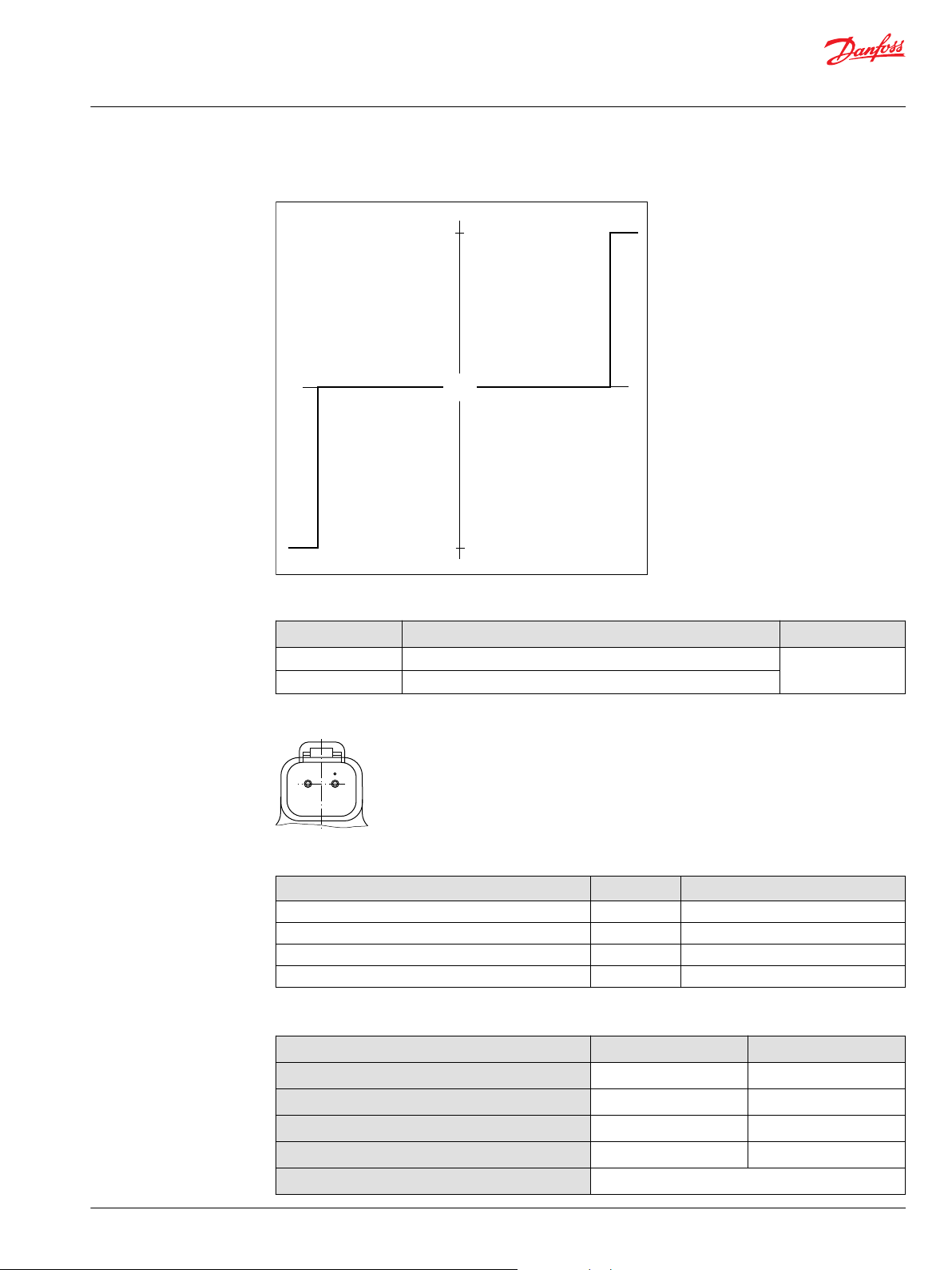
Swashplate angle sensor for EDC controls
The angle sensor detects the swash plate position with an accuracy dependent upon the calibration
effort done for the application and direction of rotation from the neutral position. At minimum the sensor
can be used for forward, neutral and reverse (FNR) detection.
The sensor works on the hall-effect technology. The implemented technology is based on a
measurement of the magnetic field direction in parallel to the chip surface. This field direction is
converted to a voltage signal at the output.
Enhanced calibration of the non-linear behavior leads to more exact calculation of the pump swashplate
angle. The 4-pin DEUTSCH connector is part of the sensor housing. The swashplate angle sensor is
available for all EDC controls for 12 V and 24 V.
Swashplate angle vs. output of supply voltage
Warning
Strong magnetic fields in the proximity of the sensor can influence the sensor signal and must be
avoided.
Contact your Danfoss representative in case the angle sensor will be used for safety functions.
Swash plate angle sensor parameters (EDC)
Parameter Minimum Typical Maximum
Supply voltage range
Supply protection
Pump neutral output (% of supply voltage)
Working range (swash plate angle)
Required supply current
Output current signal
20 | © Danfoss | February 2022 BC178386485160en-000503
Working temperature
Electrical Protection Standard Class
IP Rating IEC 60 529 IP 67
DIN 40 050, part 9 IP 69K with mating connector
EMC Immunity ISO 11452-2 100 V/m
4.5 V
DC
– – 18 V
– 50% –
–18° – 18°
– – 30 mA
– 9 mA 11 mA
–40 °C 80 °C 115 °C
5 V
DC
5.5 V
DC
DC
Page 21
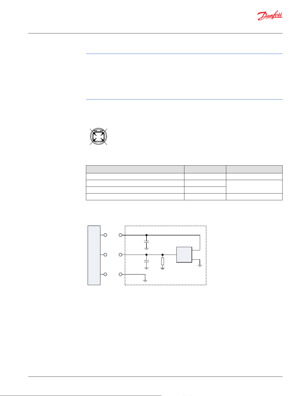
2
3
4
1
ECU
Supply
Signal
GND
GND
OUT
VCC
100 nF
20 kΩ
100 nF
Technical Information
MP1 Axial Piston Pumps Size 28/32, 38/45
Operation
Calibration of the sensor output within the software is mandatory. Vehicle neutral thresholds in the
software (±0.5°) are vehicle dependent and must consider different conditions, example: system
temperature, system pressure and/or shaft speed.
For safety function: If the sensor fails (invalid signal <10% or >90% of supply voltage), it must be sure
that the ECU will go into a diagnostic mode and shift into limited mode in order for the driver to take the
full control or the mechanical breaks should be activated. Strong magnetic fields in the proximity of the
sensor can influence the sensor signal and must be avoided.
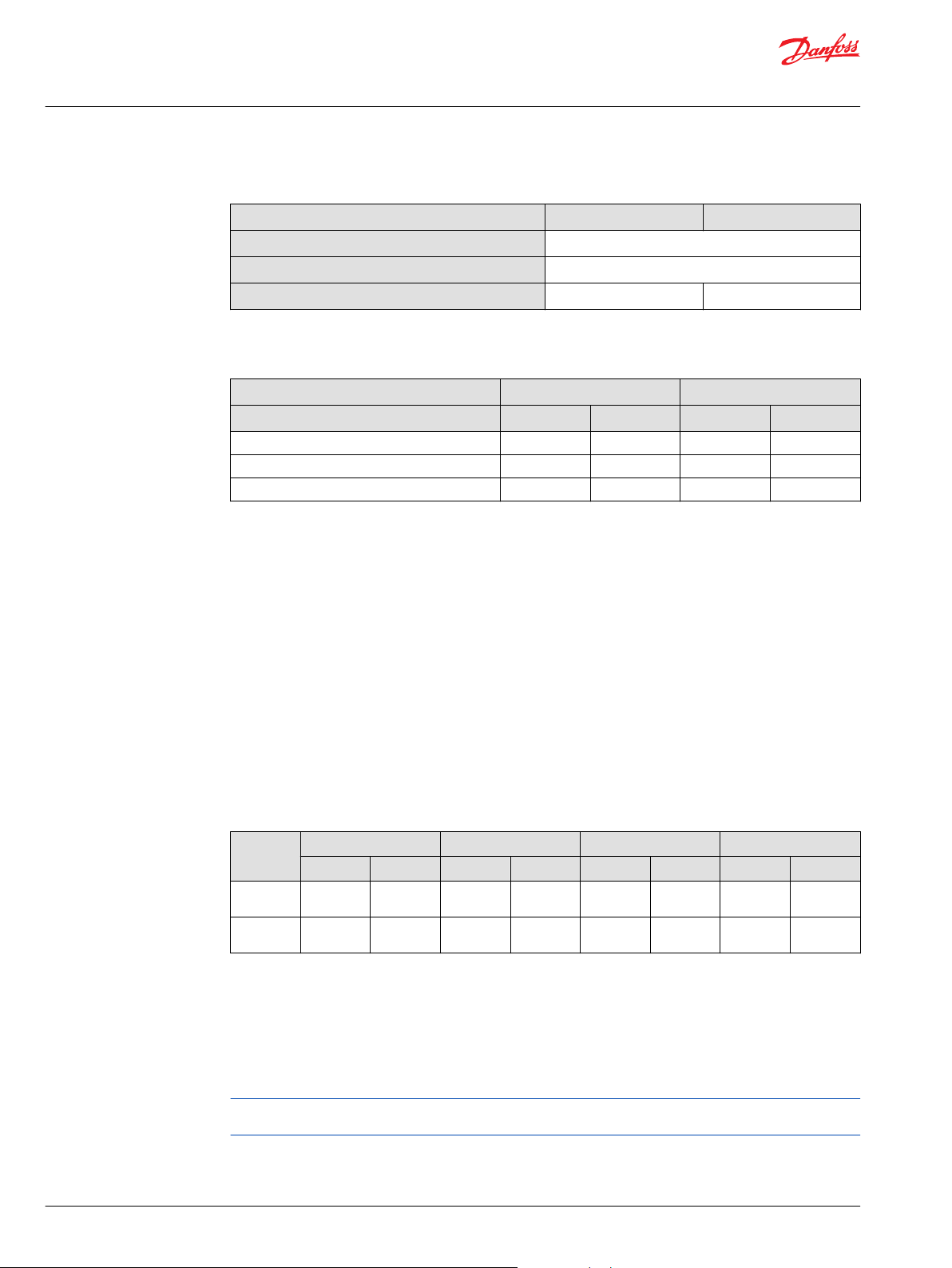
Swash plate angle sensor connector
Connector DEUTSCH, 4-pin
Pin assignment:
1. Ground (GND)
2. Not connected
3. Output signal 1 (SIG 1)
4. Supply (V+)
Connector order numbers
Description Quantity Order number
Mating connector DEUTSCH DTM06-4S-E004 1 11105824
Wedge lock WM-4S 1
Socket contact 0462-201-2031 3
Mating connector kit 1 11212713
not available
Interface with ECU (EDC)
Interface with ECU diagram
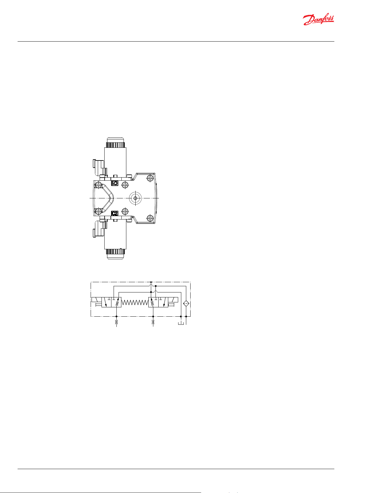
Manual displacement control
MDC principle
An MDC is a Manual proportional Displacement Control (MDC). The MDC consists of a handle on top of a
rotary input shaft. The shaft provides an eccentric connection to a feedback link. This link is connected on
its one end with a porting spool. On its other end the link is connected the pumps swashplate.
©
Danfoss | February 2022 BC178386485160en-000503 | 21
This design provides a travel feedback without spring. When turning the shaft the spool moves thus
providing hydraulic pressure to either side of a double acting servo piston of the pump.
Differential pressure across the servo piston rotates the swash plate, changing the pump’s displacement.
Simultaneously the swashplate movement is fed back to the control spool providing proportionality
between shaft rotation on the control and swashplate rotation.
Page 22
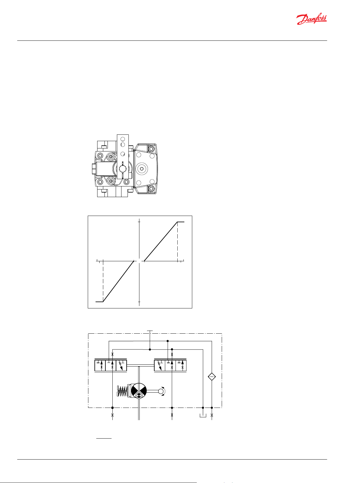
P301 749
"0"
Lever rotation
"A"
Displacement
100 %
a
-a
100 %
"B"
-b
-d
b
c
d
-c
P301 752
P005 701
M14
M5
M4
M3
Technical Information
MP1 Axial Piston Pumps Size 28/32, 38/45
Operation
The MDC changes the pump displacement between no flow and full flow into opposite directions. Under
some circumstances, such as contamination, the control spool could stick and cause the pump to stay at
some displacement.
A 170 μm screen is located in the supply line immediately before the control porting spool.
The MDC is sealed by means of a static O-ring between the actuation system and the control block. Its
shaft is sealed by means of a special O-ring which is applied for low friction. The special O-ring is
protected from dust, water and aggressive liquids or gases by means of a special lip seal.
Manual Displacement Control
Pump displacement vs. control lever rotation
MDC schematic diagram
Where:
Deadband on B side – a = 3° ±1°
Maximum pump stroke – b = 30° +2/-1°
22 | © Danfoss | February 2022 BC178386485160en-000503
Page 23
C
CCW
CW
Technical Information
MP1 Axial Piston Pumps Size 28/32, 38/45
Operation
Required customer end stop – c = 36° ±3°
Internal end stop – d = 40°
MDC torque
Torque required to move handle to maximum displacement
Torque required to hold handle at given displacement
Maximum allowable input torque
MDC operation
The MDC provides a mechanical dead-band required to overcome the tolerances in the mechanical
actuation. The MDC contains an internal end stop to prevent turning the handle into any inappropriate
position.
The MDC provides a permanent restoring moment appropriate for turning the MDC input shaft back to
neutral position only. This is required to take the backlash out of the mechanical connections between
the Bowden cable and the control.
High case pressure may cause excessive wear and the NSS to indicate that the control is not in neutral
position. In addition, if the case pressure exceeds 5 bar there is a risk of an insufficient restoring moment.
The MDC is designed for a maximum case pressure of 5 bar and a rated case pressure of 3 bar.
Customers must install some support to limit the setting range of their Bowden cable to avoid an
•
overload of the MDC.
Customers can apply their own handle design but they must care about a robust clamping
•
connection between their handle and the control shaft and avoid overload of the shaft.
Customers can connect two MDC’s on a tandem unit in such a way that the actuation force will be
•
transferred from the pilot control to the second control. The kinematic of the linkages must ensure
that either control shaft is protected from torque overload.
1.4 N•m [12.39 lbf•in ]
0.6 N•m [5.31 lbf•in]
20 N•m [177 lbf•in]
Caution
Using the internal spring force on the input shaft is not an appropriate way to return the customer
connection linkage to neutral, or to force a Bowden cable or a joystick back to neutral position. It is not
applicable for any limitation of the Bowden cable stroke, except the applied torque to the shaft will never
exceed 20 N•m.
MDC shaft rotation
Pump shaft rotation
MDC shaft rotation CW CCW CW CCW
Port A in (low) out (high) out (high) in (low)
Port B out (high) in (low) in (low) out (high)
Servo port high pressure M5 M4 M5 M4
*
As seen from shaft side.
*
Clockwise (CW) Counter-clockwise (CCW)
©
Danfoss | February 2022 BC178386485160en-000503 | 23
Page 24
P005 702
M14
M5
M4
M3
Technical Information
MP1 Axial Piston Pumps Size 28/32, 38/45
Operation
Control response
MP1 controls are available with optional control passage orifices to assist in matching the rate of swashplate response to the application requirements (e.g. in the event of electrical failure).
The time required for the pump output flow to change from zero to full flow (acceleration) or full flow to
zero (deceleration) is a net function of spool porting, orifices, and charge pressure.
A swash-plate response times table is available for each frame size. Testing should be conducted to verify
the proper orifice selection for the desired response. Typical response times at the following conditions:
Δ p = 250 bar [3626 psi]
Charge pressure = 20 bar [290 psi]
Viscosity and temperature = 30 mm²/s [141 SUS] and 50 °C [122 °F]
Speed = 1800 min-1 (rpm)
MP1 MDC response time
Code Orifice description (mm) Stroking direction (sec)
P A B Tank (A
C3
C6
C7
C8
C9
D1
D2
D3
D4
D5
– – – – 0.3 0.3 0.3 0.3
– – – 1.0 0.5 1.0 0.5 0.7
– – – 1.3 0.4 0.7 0.5 0.5
0.8 – – 0.6 1.5 2.6 1.4 1.9
1.0 – – 0.6 1.3 2.4 1.1 1.8
1.0 – – 0.8 0.9 1.6 0.8 1.1
1.3 – – 0.8 0.8 1.5 0.7 1.1
1.3 – – 1.0 0.6 1.1 0.6 0.8
1.3 1.3 1.3 1.0 0.8 1.3 0.7 0.9
0.6 0.8 0.8 0.6 3.2 4.0 2.0 2.9
+B)
Neutral to full flow Full flow to neutral
28/32 38/45 28/32 38/45
Neutral start switch (NSS)
The Neutral Start Switch (NSS) contains an electrical switch that provides a signal of whether the control
is in neutral. The signal in neutral is Normally Closed (NC).
Neutral start switch schematic
24 | © Danfoss | February 2022 BC178386485160en-000503
Page 25
P400344
Case gauge port M14
P005 701
M14
M5
M4
M3
P301 749
Technical Information
MP1 Axial Piston Pumps Size 28/32, 38/45
Operation
Neutral start switch data
Max. continuous current with switching
Max. continuous current without switching
Max. voltage
Electrical protection class
Case gauge port M14
The drain port should be used when the control is mounted on the unit’s bottom side to flush residual
contamination out of the control.
MDC w/h drain port shown
8.4 A
20 A
36 V
DC
IP67 / IP69K with mating connector
MDC schematic diagram
Lever
MDC controls are available with optional lever/handle. Align with Settings: Y module in the model code.
Standard orientation 90° from input shaft
©
Danfoss | February 2022 BC178386485160en-000503 | 25
Page 26
P003 193
P003 189
C2C1
F00A
M14
T PF00B
Technical Information
MP1 Axial Piston Pumps Size 28/32, 38/45
Operation
Forward-neutral-reverse (FNR) electic control
FNR principle
The 3-position FNR control uses an electric input signal to switch the pump to a full stroke position.
Under some circumstances, such as contamination, the control spool could stick and cause the pump to
stay at some displacement.
A 170 μm screen is located in the supply line immediately before the control porting spool.
Forward-Neutral-Reverse electric control (FNR)
FNR hydraulic schematic
26 | © Danfoss | February 2022 BC178386485160en-000503
Page 27
P003 190E
100 %
“0“
100 %
Voltage VDC
Displacement
1 2
P003 480
Technical Information
MP1 Axial Piston Pumps Size 28/32, 38/45
Operation
Pump displacement vs. electrical signal
Control current
Voltage Min. current to stroke pump Pin connections
12 V 750 mA any order
24 V 380 mA
DEUTSCH connector, 2-pin
Connector ordering data
Description Quantity Ordering data
Mating connector 1 DEUTSCH DT06-2S
Wedge lock 1 DEUTSCH W2S
Socket contact (16 and 18 AWG) 2 DEUTSCH 0462-201-16141
Danfoss mating connector kit 1 K29657
Solenoid data
Voltage 12 V 24 V
Minimum supply voltage
Maximum supply voltage (continuous)
Maximum current
Nominal coil resistance @ 20 °C [70 °F]
PWM Range
9.5 V
DC
14.6 V
DC
1050 mA 500 mA
8.4 Ω 34.5 Ω
70-200 Hz
19 V
29 V
DC
DC
©
Danfoss | February 2022 BC178386485160en-000503 | 27
Page 28
Technical Information
MP1 Axial Piston Pumps Size 28/32, 38/45
Operation
Solenoid data (continued)
Voltage 12 V 24 V
PWM Frequency (preferred)
IP Rating (IEC 60 529) + DIN 40 050, part 9
Bi-directional diode cut off voltage
*
PWM signal required for optimum control performance.
Pump output flow direction vs. control signal
Shaft rotation CW CCW
Coil energized
Port A in out out in
Port B out in in out
Servo port pressurized M5 M4 M5 M4
*
For coil location see Installation Drawings.
*
*
100 Hz
IP 67 / IP 69K (part 9 with mating connector)
28 V
DC
C1 C2 C1 C2
53 V
DC
Control response
MP1 controls are available with optional control passage orifices to assist in matching the rate of swashplate response to the application requirements (e.g. in the event of electrical failure).
The time required for the pump output flow to change from zero to full flow (acceleration) or full flow to
zero (deceleration) is a net function of spool porting, orifices, and charge pressure.
A swash-plate response times table is available for each frame size. Testing should be conducted to verify
the proper orifice selection for the desired response. Typical response times at the following conditions:
Δ p = 250 bar [3626 psi]
Charge pressure = 20 bar [290 psi]
Viscosity and temperature = 30 mm²/s [141 SUS] and 50 °C [122 °F]
Speed = 1800 min-1 (rpm)
Response time, FNR
Stroking
direction
Neutral to
full flow
Full flow to
neutral
0.8 mm [0.03 in] orifice 1.0 mm [0.04 in] orifice 1.3 mm [0.05 in] orifice No orifice
28/32 38/45 28/32 38/45 28/32 38/45 28/32 38/45
2.1 s 2.6 s 1.1 s 1.6 s 0.8 s 1.1 s 0.7 s 0.7 s
1.1 s 1.8 s 0.9 s 1.0 s 0.6 s 0.7 s 0.3 s 0.3 s
Non feedback proportional electric control (NFPE)
The Non Feedback Proportional Electric (NFPE) control is an electrical automotive control in which an
electrical input signal activates one of two proportional solenoids that port charge pressure to either side
of the pump servo cylinder. The NFPE control has no mechanical feedback mechanism.
A serviceable 170 μm screen is located in the supply line immediately before the control porting spool.
Under some circumstances, such as contamination, the control spool could stick and cause the pump to
stay at some displacement.
28 | © Danfoss | February 2022 BC178386485160en-000503
Page 29
P003 192
P003 188
C2C1
F00A
M14
T PF00B
"0"
Signal Current
mA(DC)
a b c
a
b
c
Displacement
100 %
100 %
NFPE control
∆p = 300 bar
∆p = 300 bar
∆p = 0 bar
∆p = 0 bar
P003 187E
Technical Information
MP1 Axial Piston Pumps Size 28/32, 38/45
Operation
NFPE control
NFPE schematic
The pump displacement is proportional to the solenoid signal current, but it also depends upon pump
input speed and system pressure. This characteristic also provides a power limiting function by reducing
the pump swashplate angle as system pressure increases. A typical response characteristic is shown in
the accompanying graph. Under some circumstances, such as contamination, the control spool could
stick and cause the pump to stay at some displacement.
NFPE pump displacement to input signal
Control signal requirements
Control current
Voltage a
12 V 600 mA 1080 mA 1360 mA any order
24 V 300 mA 540 mA 680 mA
*
Factory test current, for vehicle movement or application actuation expect higher or lower value.
©
Danfoss | February 2022 BC178386485160en-000503 | 29
*
b c Pin connections
Page 30
1 2
P003 480
Technical Information
MP1 Axial Piston Pumps Size 28/32, 38/45
Operation
DEUTSCH connector, 2-pin
Connector ordering data
Description Quantity Ordering data
Mating connector 1 DEUTSCH DT06-2S
Wedge lock 1 DEUTSCH W2S
Socket contact (16 and 18 AWG) 2 DEUTSCH 0462-201-16141
Danfoss mating connector kit 1 K29657
Description 12 V 24 V
Maximum current 1800 mA 920 mA
Nominal coil resistance @ 20 °C [68 °F] 3.66 Ω 14.20 Ω
Inductance 33 mH 140 mH
PWM signal frequency Range 70 – 200 Hz
IP Rating IEC 60 529 IP 67
Connector color Black
*
PWM signal required for optimum control performance.
@ 80 °C [176 °F] 4.52 Ω 17.52 Ω
Recommended
DIN 40 050, part 9 IP 69K with mating connector
*
100 Hz
Pump output flow direction vs. control signal
Shaft rotation CW CCW
Coil energized
Port A in out out in
Port B out in in out
Servo port pressurized M5 M4 M5 M4
*
For coil location see Installation drawings.
*
C1 C2 C1 C2
Control response
MP1 controls are available with optional control passage orifices to assist in matching the rate of
swashplate response to the application requirements (e.g. in the event of electrical failure). The time
required for the pump output flow to change from zero to full flow (acceleration) or full flow to zero
(deceleration) is a net function of spool porting, orifices, and charge pressure. A swashplate response
table is available for each frame indicating available swashplate response times. Testing should be
conducted to verify the proper orifice selection for the desired response.
Typical response times at the following conditions:
∆p
Viscosity and temperature
Charge pressure
Speed
250 bar [3626 psi]
30 mm2/s [141 SUS] and 50°C [122 °F]
24 bar [348 psi]
1800 min-1 (rpm)
30 | © Danfoss | February 2022 BC178386485160en-000503
Page 31

M4
M5
L2
X2
X1
Technical Information
MP1 Axial Piston Pumps Size 28/32, 38/45
Operation
Response time
Stroking
direction
Neutral to full
flow
Full flow to
neutral
0.8 mm [0.03] orifice 1.0 mm [0.04] orifice 1.3 mm [0.05] orifice
28/32 38/45 28/45 38/45 28/45 38/45
1.5 s 2.2 s 0.9 s 1.4 s 0.6 s 0.8 s
0.9 s 1.1 s 0.6 s 0.7 s 0.4 s 0.5 s
Non-feedback, proportional hydraulic (NFPH) control
The non-feedback proportional hydraulic (NFPH) control is a hydraulic proportional control in which an
input pressure signal directly controls the pump servo piston to achieve pump displacement.
MP1 pumps with NFPH control have a special servo cylinder capable of providing proportional control
with a hydraulic input.
Swashplate position is proportional to the differential signal pressure at ports X1 and X2, but
displacement is also dependent on pump speed and system pressure. This characteristic of non-feedback
controls provides a natural power limiting function by reducing the pump swashplate angle as system
pressure increases. The accompanying graph shows typical operating characteristics.
The system may require tuning through the pump orifice combinations, control pressure supply line
sizing, actuation device output pressure and flow adjustments to achieve proper vehicle performance
characteristics.
Non-feedback proportional hydraulic control schematic
Pump flow direction with NFPH control
Input Shaft Rotation
Port A flow
Port B flow
High servo gauge port
©
Danfoss | February 2022 BC178386485160en-000503 | 31
CW CCW
Out In In Out
In Out Out In
M4 M5 M4 M5
Page 32

"0"
Input Signal Pressure
(bar)
a b c
a
b
c
Displacement
100 %
100 %
NFPH control
∆
p = 300 bar
∆
p = 300 bar
∆
p = 0 bar
∆
p = 0 bar
Technical Information
MP1 Axial Piston Pumps Size 28/32, 38/45
Operation
NFPH pump displacement to Input signal
NFPH input signal pressure (bar)
Frame size a b c
28/32 5.5 13.7 17
38/45 5 12.75 16
The values provided in the table above are approximations at 1800 RPM and system delta pressures as
indicated in the graph provided. The values are dependent on input speed and delta pressure operating
conditions.
Control response
MP1 controls are available with optional control passage orifices to assist in matching the rate of
swashplate response to the application requirements (e.g. in the event of electrical failure). The time
required for the pump output flow to change from zero to full flow (acceleration) or full flow to zero
(deceleration) is a net function of spool porting, orifices, and charge pressure. A swashplate response
table is available for each frame indicating available swashplate response times. Testing should be
conducted to verify the proper orifice selection for the desired response.
Typical response times at the following conditions:
∆p
Viscosity and temperature
Charge pressure
Speed
Response time
Stroking
direction
Neutral to full
flow
Full flow to
neutral
250 bar [3626 psi]
30 mm2/s [141 SUS] and 50°C [122 °F]
24 bar [348 psi]
1800 min-1 (rpm)
0.8 mm [0.03] orifice 1.0 mm [0.04] orifice 1.3 mm [0.05] orifice
28/32 38/45 28/45 38/45 28/45 38/45
1.5 s 2.2 s 0.9 s 1.4 s 0.6 s 0.8 s
0.9 s 1.1 s 0.6 s 0.7 s 0.4 s 0.5 s
32 | © Danfoss | February 2022 BC178386485160en-000503
Page 33

P003 544
CAN PPC
PSC
PPU
CC2
CC1
WARRANTY VOID IF REMOVED
CC3
Technical Information
MP1 Axial Piston Pumps Size 28/32, 38/45
Operation
Automotive control (AC)
The Automotive control (AC) is an electric NFPE control with an integrated micro-controller, installed on
the pump.
The integrated micro-controller enhanced control performance with a flexible, configurable control
scheme for an entire single path propel transmission. It can be used in combination with fixed and
variable displacement hydraulic motors. With the pre-installed application software and easily
changeable control parameters, it is possible to tailor the vehicle’s driving behavior to the individual
requirements of the customer.
The H1 automotive control is divided into 2 systems:
•
AC-1
•
AC-2
AC-2 is an extension of AC-1 that features an integrated pump swash plate angle sensor and software
enabled functions such as swash plate control.
Mode types
The application software provides 3 different hydrostatic propel methods, defined as mode types, which
can be used individually.
Automotive Load
dependent
Non-Automotive
Load independent
Torque controlled driving behavior. Setpoint for the drive curve is the engine
rpm.
Speed controlled driving mode. Setpoint for the drive curve is a joystick or
drive pedal signal, independent of the engine rpm. The best performance will
achieved with an AC-2 Swash Plate Sensor.
Creep-Automotive
Load dependent
Torque controlled driving behavior (like Automotive). Setpoint for the drive
curve is the engine rpm. The setpoint can be reduced by the creep
potentiometer if a high engine rpm in combination with low vehicle speed is
needed.
Basic functions
Four selectable system modes, selectable via switch
•
Individual settings for forward and reverse driving direction (4 x 2 curves)
•
Independent pump and hydraulic motor profiling and ramping for each mode
•
Electric drive pedal connection
•
Electronic inching function without separate control valve
•
©
Danfoss | February 2022 BC178386485160en-000503 | 33
Page 34

Technical Information
MP1 Axial Piston Pumps Size 28/32, 38/45
Operation
Electric creep mode potentiometer
•
Configurable System Mode and Direction change
•
Load independent pump displacement control with integrated Swash Plate Angle Sensor (AC-2)
•
Hydraulic motor displacement control including brake pressure defeat function
•
Performance functions
ECO fuel saving mode with automatic reduction of the engine speed during transport (Cruise control)
•
Vehicle constant speed drive control
•
Vehicle speed limitation
•
Dynamic brake light, automatic park brake, reverse buzzer and status LED outputs
•
Vehicle speed controlled output function
•
Temperature compensation for predictable performance
•
Advanced CAN J1939 interface for the information exchange with the vehicle control system
•
Protection and safety functions
Safety controlled vehicle start protection with engine speed check, battery check and FNR must be in
•
neutral, etc.
Operator presence detection
•
Hydraulic system overheat and low-temperature protection
•
Hydraulic motor over speed protection
•
Park brake test mode for roller applications to fulfill SAE J1472/EN500-4
•
SIL2 compliant
•
Engine control and protection
CAN J1939 engine interface
•
Engine speed control via drive pedal with safety controlled monitoring function
•
Engine antistall protection
•
Engine over speed protection during inching
•
Engine speed dependent retarder control
•
Engine cold start protection
•
Installation features
Factory calibration for hysteresis compensation
•
Starting current adjustment in the factory
•
Pre-installed application software and parameter files
•
For more information, see Integrated Automotive Control (AC) for MP1 and H1P Single Pumps 28-250
Technical Information, BC152986482596.
34 | © Danfoss | February 2022 BC178386485160en-000503
Page 35

Hydraulic logic Port X7
P400346
X7M14
C2C1
P400349
Technical Information
MP1 Axial Piston Pumps Size 28/32, 38/45
Operation
Control-cut-off valve (CCO valve)
The pump offers an optional control cut off valve integrated into the control. This valve will block charge
pressure to the control, allowing the servo springs to de-stroke the pump regardless of the pump´s
primary control input. There is also a hydraulic logic port, X7, which can be used to control other machine
functions, such as spring applied pressure release brakes. The pressure at X7 is controlled by the control
cut off solenoid. The X7 port would remain plugged if not needed.
In the normal (de-energized) state of the solenoid charge flow is prevented from reaching the controls. At
the same time the control passages and the X7 logic port are connected and drained to the pump case.
The pump will remain in neutral, or return to neutral, independent of the control input signal. Return to
neutral time will be dependent on oil viscosity, pump speed, swashplate angle, and system pressure.
When the solenoid is energized, charge flow and pressure is allowed to reach the pump control. The X7
logic port will also be connected to charge pressure and flow.
The solenoid control is intended to be independent of the primary pump control making the control cut
off an override control feature. It is however recommended that the control logic of the CCO valve be
maintained such that the primary pump control signal is also disabled whenever the CCO valve is deenergized. Other control logic conditions may also be considered.
All EDC and MDC controls are available with a CCO valve.
The response time of the unit depends on the control type and the control orifices used.
The CCO-valve is available with 12 V or 24 V solenoid.
EDC with CCO
Control
Schematic
©
Danfoss | February 2022 BC178386485160en-000503 | 35
Page 36

P005 703
M14
X7
1 2
Technical Information
MP1 Axial Piston Pumps Size 28/32, 38/45
Operation
MDC with CCO
Control
Schematic
CCO solenoid data
Nominal supply voltage 12 V 24 V
Supply voltage Maximum
Bi-directional diode cut off voltage
Nominal coil resistance at 20 °C
Supply current Maximum
PWM frequency Range
Electrical protection class
36 | © Danfoss | February 2022 BC178386485160en-000503
Minimum
Minimum
Preferred
14.6 V 29 V
9.5 V 19 V
28 V 53 V
10.7 Ω 41.7 Ω
850 mA 430 mA
580 mA 300 mA
50 – 200 Hz
100 Hz
IP67 / IP69K with mating connector
Page 37

C
Servo piston
Displacement limiter
Servo cylinder
P400347
Technical Information
MP1 Axial Piston Pumps Size 28/32, 38/45
Operation
CCO solenoids are design for battery voltage application within the voltage range in the table above, in
consideration of a wide range of environmental temperature common for known hydraulic applications.
Closed loop PWM current supply can be also applied and is helpful in case that the voltage range is
exceeded, or ambient temperature could rise in an unusual manner.
Brake gauge port with MDC
Caution
It is not recommended to use brake port for any external flow consumption to avoid malfunction of CCO
function.
Displacement limiter
All pumps are designed with optional mechanical displacement (stroke) limiters factory set to max.
displacement.
The maximum displacement of the pump can be set independently for forward and reverse using the
two adjustment screws to mechanically limit the travel of the servo piston. Adjustment procedures are
found in the Service Manual. Adjustments under operating conditions may cause leakage. The
adjustment screw can be completely removed from the threaded bore if backed out to far.
Displacement limiter
Displacement change (approximate)
Parameter 28 32 38 45
3
1 Turn of
displacement limiter screw
Internal wrench size
External wrench size
Torque for
external hex seal lock nut
©
Danfoss | February 2022 BC178386485160en-000503 | 37
2.9 cm
[0.18 in3]
4 mm
13 mm
23 N•m [204 lbf•in]
3.3 cm
[0.20 in3]
3
3.56 cm
[0.22 in3]
3
4.22 cm
[0.26 in3]
3
Page 38

4
3
2
1
5
6
P006035
Technical Information
MP1 Axial Piston Pumps Size 28/32, 38/45
Operation
Speed sensor
The speed sensor is designed for rugged outdoor, mobile or heavy industrial speed sensing applications.
The detection of the speed is contactless and does not need any calibration or adjustments.
For more information, see Speed and Temperature Sensor, Technical Information, BC152886482203.
Temperature range
Parameter Minimum Maximum
Operation temperature range -40 °C 104 °C
115°C intermittent = short term; t < 1min per incident and not exceeding 2 % of duty cycle based loadlife.
Output pulses
The expected number of output pulses per revolution is shown below.
The number of output (speed) pulses
MP1P size 28/32 38/45
Pulses (per rev) 9 11
Mating connectors
There are available two types of mating connectors Assembly Bag DEUTSCH DTM06-6S, Black and Grey.
Ordering number
11033865 11033863
Assembly Bag, DEUTSCH DTM06-6S-E004; black, (24-20
AWG) 0.21 -0.52 mm²
Assembly Bag, DEUTSCH DTM06-6S, gray, (24-20 AWG)
0.21 -0.52 mm²
Speed sensor 4.5 – 8 V technical data
Speed sensor connector, 6-pin
1. Speed signal 2
2. NC
3. Speed signal 1
4. Supply
5. Ground
6. Temperature
Technical data
Parameter Min. Nom. Max. Note
Supply voltage
Supply protection
Max. required supply current
Max. output current
Operation mode
Temperature signal
Output low
4.5 V
DC
– – 30 V
– – 25 mA At supply voltage
– – 50 mA
NPN & PNP Push-Pull amplifier
-40°C = 2.318V – 100°C = 0.675V
5 % 8.5 % 12 %
5 V
8 V
DC
DC
DC
Regulated supply voltage.
Reverse polarity protected.
Shuts off above 9 V.
Ratiometric output voltage
Low state > 0 V to provide wire
fault detection
38 | © Danfoss | February 2022 BC178386485160en-000503
Page 39

T = –1481.96 + √ 2.1962 · 106 +
(1.8639 – Vº)
3.88 · 10
-6
0
0
10
20
30
40
50
60
70
80
90
-100 100 200 300 400 500 600 700 800 900 1000
P003531E
Real temperature
Temperature
Signal
T90 definition
T
90
Time (S)
Temperature (°C)
90 % of ∆ Temp
∆ Temp
Technical Information
MP1 Axial Piston Pumps Size 28/32, 38/45
Operation
Technical data (continued)
Parameter Min. Nom. Max. Note
Output high
Detectable frequency range
Ordering number
Color of connector
Temperature sensor data
For calculation of the case fluid temperature and the output signal voltage, see the formulas below:
VO – Measured output voltage (V)
Vo= (-3.88 • 10-6 • T2) + (-1.15 • 10-2 • T) + 1.8639
T – Temperature (°C)
88 % 91.5 % 95 %
1 Hz – 10 000 Hz
149055
Black
Output signal voltage vs. Temperature
Temperature range
-55 °C** -40 °C -30 °C 0 °C +30 °C
2.485 V 2.318 V 2.205 V 1.864 V 1.515 V 0.919 V 0.675 V 0.303 V
*
Accuracy: ±1. 5 to ± 4 °C
**
Accuracy: ±2.5 to ± 5 °C
*
+80 °C +100 °C +130 °C
Response time in fluid
T90 definition
**
©
Danfoss | February 2022 BC178386485160en-000503 | 39
Response time in fluid (T90) = 360 s
Page 40

W
Technical Information
MP1 Axial Piston Pumps Size 28/32, 38/45
Operating parameters
Input speed
Minimum speed is the lowest input speed recommended during engine idle condition. Operating below
minimum speed limits pump’s ability to maintain adequate flow for lubrication and power transmission.
Rated speed is the highest input speed recommended at full power condition. Operating at or below
this speed should yield satisfactory product life.
Maximum speed is the highest operating speed permitted. Exceeding maximum speed reduces product
life and can cause loss of hydrostatic power and braking capacity. Never exceed the maximum speed
limit under any operating conditions.
Operating conditions between Rated speed and Maximum speed should be restricted to less than full
power and to limited periods of time. For most drive systems, maximum unit speed occurs during
downhill braking or negative power conditions.
During hydraulic braking and downhill conditions, the prime mover must be capable of providing
sufficient braking torque in order to avoid pump over speed. This is especially important to consider for
turbocharged and Tier 4 engines.
Warning
Unintended vehicle or machine movement hazard.
Exceeding maximum speed may cause a loss of hydrostatic drive line power and braking capacity. You
must provide a braking system, redundant to the hydrostatic transmission, sufficient to stop and hold the
vehicle or machine in the event of hydrostatic drive power loss.
System pressure
System pressure is the differential pressure between system ports A and B. It is the dominant operating
variable affecting hydraulic unit life. High system pressure, which results from high load, reduces
expected life. Hydraulic unit life depends on the speed and normal operating, or weighted average,
pressure that can only be determined from a duty cycle analysis.
Application pressure is the high pressure relief setting normally defined within the order code of the
pump. This is the applied system pressure at which the driveline generates the maximum calculated pull
or torque in the application.
Maximum working pressure is the highest recommended Application pressure. Maximum working
pressure is not intended to be a continuous pressure. Propel systems with Application pressures at, or
below, this pressure should yield satisfactory unit life given proper component sizing.
Maximum pressure is the highest allowable Application pressure under any circumstance. Application
pressures above Maximum Working Pressure will only be considered with duty cycle analysis and factory
approval. Pressure spikes are normal and must be considered when reviewing maximum working
pressure.
All pressure limits are differential pressures referenced to low loop (charge) pressure. Subtract low loop
pressure from gauge readings to compute the differential.
Minimum low loop pressure (above case pressure) is the lowest pressure allowed to maintain a safe
working condition in the low side of the loop.
40 | © Danfoss | February 2022 BC178386485160en-000503
Page 41

C
Technical Information
MP1 Axial Piston Pumps Size 28/32, 38/45
Operating parameters
Charge pressure
An internal charge relief valve regulates charge pressure. Charge pressure maintains a minimum pressure
in the low side of the transmission loop.
The charge pressure setting listed in the order code is the set pressure of the charge relief valve with the
pump in neutral, operating at 1800 min-1 [rpm], and with a fluid viscosity of 32 mm2/s [150 SUS]. Pumps
configured with no charge pump (external charge supply) are set with a charge flow of 18.9 l/min [5.0 US
gal/min] and a fluid viscosity of 32 mm2/s [150 SUS].
The charge pressure setting is referenced to case pressure.
Charge pump inlet pressure
At normal operating temperature charge inlet pressure must not fall below rated charge inlet pressure
(vacuum).
Minimum charge inlet pressure is only allowed at cold start conditions. In some applications it is
recommended to warm up the fluid (e.g. in the tank) before starting the engine and then run the engine
at limited speed until the fluid warms up.
Maximum charge pump inlet pressure may be applied continuously.
Case pressure
Temperature
Under normal operating conditions, the rated case pressure must not be exceeded. During cold start case
pressure must be kept below maximum intermittent case pressure. Size drain plumbing accordingly.
Caution
Possible component damage or leakage
Operation with case pressure in excess of stated limits may damage seals, gaskets, and/or housings,
causing external leakage. Performance may also be affected since charge and system pressure are
additive to case pressure.
The high temperature limits apply at the hottest point in the transmission, which is normally the motor
case drain. The system should generally be run at or below the rated temperature.
The maximum intermittent temperature is based on material properties and should never be
exceeded.
Cold oil will not affect the durability of the transmission components, but it may affect the ability of oil to
flow and transmit power; therefore temperatures should remain 16 °C [30 °F] above the pour point of the
hydraulic fluid.
The minimum temperature relates to the physical properties of component materials. Size heat
exchangers to keep the fluid within these limits. Danfoss recommends testing to verify that these
temperature limits are not exceeded.
Ensure fluid temperature and viscosity limits are concurrently satisfied.
©
Danfoss | February 2022 BC178386485160en-000503 | 41
Page 42

Technical Information
MP1 Axial Piston Pumps Size 28/32, 38/45
Operating parameters
Viscosity
Viscosity For maximum efficiency and bearing life, ensure the fluid viscosity remains in the
recommended range.
The minimum viscosity should be encountered only during brief occasions of maximum ambient
temperature and severe duty cycle operation.
The maximum viscosity should be encountered only at cold start.
42 | © Danfoss | February 2022 BC178386485160en-000503
Page 43
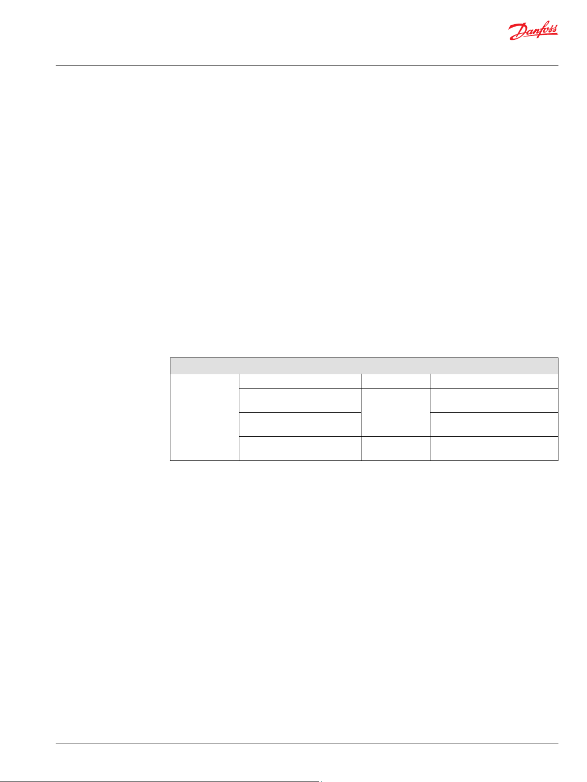
Technical Information
MP1 Axial Piston Pumps Size 28/32, 38/45
System design parameters
Filtration system
To prevent premature wear, ensure that only clean fluid enters the hydrostatic transmission circuit. A
filter capable of controlling the fluid cleanliness to ISO 4406, class 22/18/13 (SAE J1165) or better, under
normal operating conditions, is recommended.These cleanliness levels cannot be applied for hydraulic
fluid residing in the component housing/case or any other cavity after transport.
Filtration strategies include suction or pressure filtration. The selection of a filter depends on a number of
factors including the contaminant ingression rate, the generation of contaminants in the system, the
required fluid cleanliness, and the desired maintenance interval. Filters are selected to meet the above
requirements using rating parameters of efficiency and capacity.
Filter efficiency can be measured with a Beta ratio (βX). For simple suction-filtered closed circuit
transmissions and open circuit transmissions with return line filtration, a filter with a β-ratio within the
range of β
and closed circuits with cylinders being supplied from the same reservoir, a higher filter efficiency is
recommended. This also applies to systems with gears or clutches using a common reservoir. For these
systems, a charge pressure or return filtration system with a filter β-ratio in the range of β
10) or better is typically required.
Because each system is unique, only a thorough testing and evaluation program can fully validate the
filtration system. Please see Design Guidelines for Hydraulic Fluid Cleanliness Technical Information,
BC152886482150 for more information.
Cleanliness level and βx-ratio
Filtration
(recommended
minimum)
1
Filter βx-ratio is a measure of filter efficiency defined by ISO 4572. It is defined as the ratio of the number of particles
greater than a given diameter (“x” in microns) upstream of the filter to the number of these particles downstream of
the filter.
= 75 (β10 ≥ 2) or better has been found to be satisfactory. For some open circuit systems,
35-45
Cleanliness per ISO 4406 22/18/13
Efficiency (charge pressure
filtration)
Efficiency (suction and return line
filtration)
Recommended inlet screen mesh
size
= 75 (β10 ≥
15-20
1
β
= 75 (β10 ≥ 10)
15-20
β-ratio
β
= 75 (β10 ≥ 2)
35-45
µm 100 – 125
Filtration
Suction filtration
A suction circuit uses an internal charge pump. The filter is placed between the reservoir and the charge
pump inlet. Do not exceed the inlet vacuum limits during cold start conditions.
©
Danfoss | February 2022 BC178386485160en-000503 | 43
Page 44
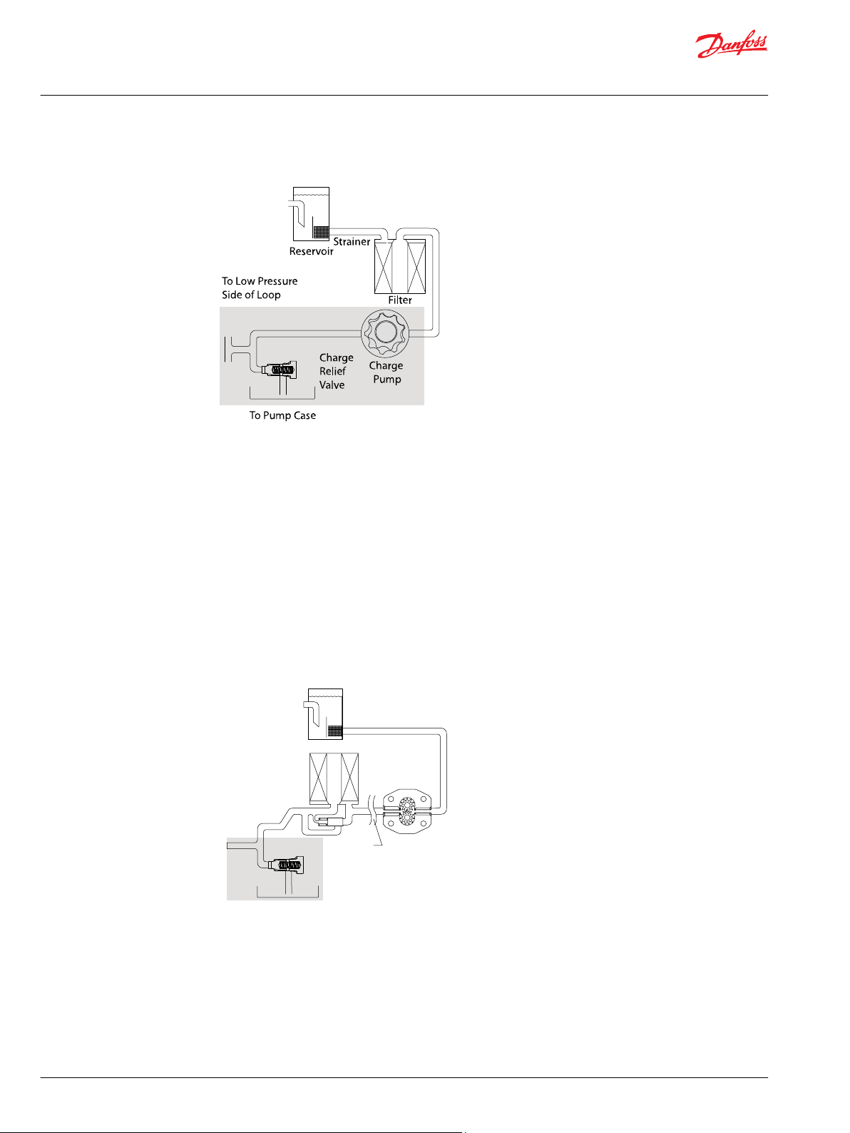
P400032
Reservoir
Filter
with bypass
Charge
pump
Charge relief valve
To pump case
To Low Pressure
side of loop
Strainer
Potential
workfunction
circuit
P400031
Technical Information
MP1 Axial Piston Pumps Size 28/32, 38/45
System design parameters
Suction filtration
Charge pressure filtration
In a pressure filtration system the pressure filter is remotely mounted in the circuit, downstream of the
charge supply. Pressure filtration is possible with, and without, an internal charge pump. Filters used in
charge pressure filtration circuits should be rated to at least 35 bar [508 psi] pressure. Danfoss
recommends locating a 100 – 125 micron screen in the reservoir or in the charge inlet when using charge
pressure filtration.
A filter bypass valve is necessary to prevent damage to the hydrostatic system. In the event of high
pressure drop associated with a blocked filter or cold start-up conditions, fluid may bypass the filter
temporarily. Avoid working with an open bypass for an extended period. A visual or electrical bypass
indicator is preferred. Proper filter maintenance is mandatory.
Charge pressure filtration
44 | © Danfoss | February 2022 BC178386485160en-000503
Page 45

W
C
Technical Information
MP1 Axial Piston Pumps Size 28/32, 38/45
System design parameters
Independent braking system
Warning
Unintended vehicle or machine movement hazard.
The loss of hydrostatic drive line power, in any mode of operation (forward, neutral, or reverse) may cause
the system to lose hydrostatic braking capacity. You must provide a braking system, redundant to the
hydrostatic transmission, sufficient to stop and hold the vehicle or machine in the event of hydrostatic
drive power loss.
Fluid selection
Ratings and performance data are based on operating with hydraulic fluids containing oxidation, rust
and foam inhibitors. These fluids must possess good thermal and hydrolytic stability to prevent wear,
erosion, and corrosion of pump components.
Caution
Never mix hydraulic fluids of different types.
Reservoir
Case drain
Charge pump
The hydrostatic system reservoir should accommodate maximum volume changes during all system
operating modes and promote de-aeration of the fluid as it passes through the tank.
A suggested minimum total reservoir volume is 5/8 of the maximum charge pump flow per minute with a
minimum fluid volume equal to 1/2 of the maximum charge pump flow per minute. This allows 30
seconds fluid dwell for removing entrained air at the maximum return flow. This is usually adequate to
allow for a closed reservoir (no breather) in most applications.
Locate the reservoir outlet (charge pump inlet) above the bottom of the reservoir to take advantage of
gravity separation and prevent large foreign particles from entering the charge inlet line. A 100-125 µm
screen over the outlet port is recommended.
Position the reservoir inlet (fluid return) to discharge below the normal fluid level, toward the interior of
the tank. A baffle (or baffles) will further promote de-aeration and reduce surging of the fluid.
The pump housing must remain full of oil at all times. The MP1 pump is equipped with two case drain
ports to provide flexibility for hose routing and pump installation. Connect a line from one of the case
drain ports to the reservoir. Case drain fluid is typically the hottest fluid in the system.
Charge flow is required on MP1 pumps. The charge pump provides flow to make up for system leakage,
maintain a positive pressure in the main circuit, and provide flow for cooling and filtration.
Many factors influence the charge flow requirements and the resulting charge pump size selection. These
factors include system pressure, pump speed, pump swashplate angle, type of fluid, temperature, size of
heat exchanger, length and size of hydraulic lines, auxiliary flow requirements, hydrostatic motor type,
etc. When initially sizing and selecting hydrostatic units for an application, it is frequently not possible to
have all the information necessary to accurately evaluate all aspects of charge pump size selection.
Unusual application conditions may require a more detailed review of charge pump sizing. Charge
pressure must be maintained at a specified level under all operating conditions to prevent damage to the
transmission. Danfoss recommends testing under actual operating conditions to verify this.
©
Danfoss | February 2022 BC178386485160en-000503 | 45
Page 46

Technical Information
MP1 Axial Piston Pumps Size 28/32, 38/45
System design parameters
Charge pump sizing/selection
In most applications a general guideline is that the charge pump displacement should be at least 10 % of
the total displacement of all components in the system. Unusual application conditions may require a
more detailed review of charge flow requirements. Please refer to Selection of Drive line Components,
BC157786484430 for a detailed procedure.
System features and conditions which may invalidate the 10 % guideline include (but are not limited to):
Continuous operation at low input speeds {< 1500 min-1 (rpm)}
•
High shock loading and/or long loop lines
•
High input shaft speeds
•
LSHT motors with large displacement and/or multiple LSHT motors
•
High flushing flow requirements
•
Automotive style operation where input speeds fluctuate or operate below 800 min-1 (rpm)
•
Contact your Danfoss representative for application assistance if your application includes any of these
conditions.
46 | © Danfoss | February 2022 BC178386485160en-000503
Page 47

Charge pump flow
5.0
0.0
10.0
15.0
20.0
25.0
30.0
35.0
40.0
P400354
0
1000500 1500 2000 2500 3000 3500 4000
9 cm3 12 cm3
[l/min]
[kW]
Speed [min-1] Speed [min-1]
9 cm3 12 cm3
Charge pump power requirements
0.0
0.5
1.0
1.5
2.0
2.5
3.0
0
1000500 1500 2000 2500 3000 3500 4000
Technical Information
MP1 Axial Piston Pumps Size 28/32, 38/45
System design parameters
Charge pump output flow
Charge pump flow and power curves, 9/12 cm
Charge pressure: 20 bar [290 psi]
Viscosity: 11 mm2/s [63 SUS]
Temperature: 80 °C [176 °F]
3
Bearing life and external shaft loading
Bearing life is a function of speed, system pressure, charge pressure, and swashplate angle, plus any
external side or thrust loads. Other life factors include oil type and viscosity. The influence of swashplate
angle includes displacement as well as direction. External loads are found in applications where the
pump is driven with side/thrust load (belt or gear) as well as in installations with misalignment and
improper concentricity between the pump and drive coupling. All external side loads will act to reduce
the normal bearing life of a pump.
In vehicle propel drives with no external shaft loads and where the system pressure and swashplate angle
are changing direction and magnitude regularly, the normal B10 bearing life (90% survival) will exceed
the hydraulic load-life of the unit.
In non propel drives such as vibratory drives, conveyor drives, or fan drives, the operating speed and
pressure are often nearly constant and the swashplate angle is predominantly at maximum. These drives
have a distinctive duty cycle compared to a propulsion drive. In these types of applications a bearing life
review is recommended.
MP1 pumps are designed with bearings that can accept some external radial. When external loads are
present, the allowable radial shaft loads are a function of the load position relative to the mounting
flange, the load orientation relative to the internal loads, and the operating pressures of the hydraulic
unit. In applications where external shaft loads can not be avoided, the impact on bearing life can be
minimized by proper orientation of the load. Optimum pump orientation is a consideration of the net
loading on the shaft from the external load, the pump rotating group, and the charge pump load.
©
Danfoss | February 2022 BC178386485160en-000503 | 47
Page 48

L
Re
P400320
90
Re
180
Re
F
cp
F
b
Technical Information
MP1 Axial Piston Pumps Size 28/32, 38/45
System design parameters
In applications where the pump is operated such that nearly equal amounts of forward vs reverse
•
swashplate operation is experienced; bearing life can be optimized by orientating the external side
load to the 0 or 180 deg position (90 deg to rotating group load Fb). See drawing.
In applications where the pump is operated such that the swashplate is predominantly (>75%) on
•
one side of neutral (e.g. vibratory, conveyor, typical propel); bearing life can be optimized by
orientating the external side load generally opposite of the internal rotating group load, Fb. The
direction of the internal loading is a function of rotation and system port, which has flow out.
Avoid axial thrust loads in either direction.
•
The maximum allowable radial loads (Re), based on the maximum external moment (Me) and the
distance (L) from the mounting flange to the load, may be determined from the tables below and the
cross section drawing.
The maximum allowable radial load is calculated as: Re = Me / L
Contact your Danfoss representative for an evaluation of unit bearing life if continuously applied external
radial loads are 25% or more of the maximum allowable, or if thrust loads are known to exist. Use tapered
output shafts or clamp-type couplings where radial shaft side loads are present.
Shaft loading parameters
Re Maximum external radial load
Me Maximum external moment
L Distance from mounting flange to point of load
Fb Internal rotating group load
Te Thrust external load
Fcp Force of charge pump
External radial shaft load
48 | © Danfoss | February 2022 BC178386485160en-000503
Page 49

Technical Information
MP1 Axial Piston Pumps Size 28/32, 38/45
System design parameters
Hydraulic unit life
Hydraulic unit life is defined as the fatigue life expectancy of the hydraulic components. It is a function of
speed and system pressure; however, system pressure is the dominant variable. High pressure, which
results from high load, reduces expected hydraulic unit life.
System component selection is based on determination of the application maximum loads and speeds.
Testing is recommended to secure duty cycle data in which to predict hydraulic unit life. Contact your
Danfoss representative for assistance in unit life determination. If duty cycle data is not available, normal
input power and maximum pump displacement can be used to determine an application pressure in
which to predict life.
MP1 pumps will meet most application hydraulic unit life expectancies if applied within the parameters
specified in this manual and chosen considering the guidelines within Danfoss publication Selection of
Driveline Components BC157786484430. For more detailed information on hydraulic unit life, see
Danfoss publication Pressure and Speed Limits BC152886484313.
Mounting flange loads
Shock load moment is the result of an instantaneous jolt to the system. Continuous load moments are
generated by the typical vibratory movement of the application. Avoid excessive loading of the
mounting flange such as adding tandem mounted auxiliary pumps and/or subjecting pumps to high
shock loads. Design pump applications to stay within the allowable shock load moment and allowable
continuous load moment.
Use the following formulas to estimate overhung load moment for multiple pump mountings:
MS = GS (W1L1 + W2L2 + ... +WnLn)
MC = GC (W1L1 + W2L2 + ... +WnLn)
Refer to the Installation Drawings section to find pump length (L). Refer to the table Technical
Specifications in the Specifications section, to find pump weight (W). An exact measure of W will depend
on the pump’s features.
Overhung loading parameters
M
s
M
c
G
s
G
c
W
n
L
n
Shock load moment
Continuous load moment
Maximum shock acceleration (Gs)
Continuous (vibratory) acceleration (Gs)
Weight of nth pump
Distance from mounting flange to center of gravity of nth pump
The tables below show allowable overhung load moment values. If system parameters exceed these
values add additional pump support.
Allowable overhung parameters
Frame size
28/32 1100 [9736] 2000 [17702]
38/45 1500 [13276] 2800 [24782]
Continuous load moment (Mc) 107 cycles
N•m [in·lbf]
Shock load moment (Ms) 103 cycles
N•m [in·lbf]
©
Danfoss | February 2022 BC178386485160en-000503 | 49
Page 50

L1
L2
Mounting flange
P400332
CG
Pump 1
CG
Pump 2
Technical Information
MP1 Axial Piston Pumps Size 28/32, 38/45
System design parameters
Shaft loading parameters
This illustration shows two single pumps in tandem.
Estimated maximum and continuous acceleration factors for some typical applications are shown.
Applications which experience extreme resonant vibrations may require additional pump support.
Typical continuous (vibratory) values can vary significantly due to changes in engine and pump
configuration and mounting methods.
G-factors for sample applications
Application Continuous (vibratory) acceleration (Gc) Maximum (shock) acceleration (Gs)
Trencher
(rubber tires)
Asphalt paver 2 6
Windrower 2 5
Aerial lift 1.5 4
Turf care vehicle 1.5 4
Vibratory roller 6 10
3 8
* Applications which experience extreme resonant vibrations require addition pump support.
50 | © Danfoss | February 2022 BC178386485160en-000503
Page 51

Technical Information
MP1 Axial Piston Pumps Size 28/32, 38/45
System design parameters
Shaft torques
Shaft selection
Base shaft selection on a review of the maximum torque required by the application and the maximum
torque available from the prime mover. Application duty cycle and continuous torque rating of the prime
mover are the main variable to consider when selecting a shaft.
Shaft torque and splines lubrication
The rated torque is a measure of tooth wear and is the torque level at which a normal spline life of 1 x
107 shaft revolutions can be expected. The rated torque presumes a regularly maintained minimum level
of lubrication via a moly-disulfide grease in order to reduce the coefficient of friction and to restrict the
presence of oxygen at the spline interface. It is also assumed that the mating spline has a minimum
hardness of Rc 55 and full spline depth. The rated torque is proportional to the minimum active spline
length.
However, a spline running in oil-flooded environment provides superior oxygen restriction in addition to
contaminant flushing. The rated torque of a flooded spline can increase to that of the maximum
published rating. A flooded spline would be indicative of a pump driven by a pump drive or plugged into
an auxiliary pad of a pump.
Maximum torque ratings are based on torsional fatigue strength considering 1 x 10⁵ full load reversing
cycles.
Maintaining a spline engagement at least equal to the pitch diameter will also maximize spline life. Spline
engagements of less than ¾ pitch diameter are subject to high contact stress and spline fretting.
Shaft torque for tapered shafts
The rated torque is based on the contact pressure between the shaft and hub surfaces with poor contact
areas. With increased quality of the contact areas, the contact pressure between shaft and hub is
increased, allowing higher torque to be transmitted.
A key is intended as an installation aid only. Any torque carried by the key as a result of poor contact area
or mis-alignment will limit the torque carrying capability of the shaft significantly.
Maximum torque rating is based on an ideal contact area of 100% and the retaining nut properly
torqued. This allows for the highest contact pressure between the shaft and the mating hub.
©
Danfoss | February 2022 BC178386485160en-000503 | 51
Page 52

P400348
Me1 for the second pump
M
e3
for the next pump
Me1 for the first pump
Me input torque
Technical Information
MP1 Axial Piston Pumps Size 28/32, 38/45
System design parameters
Shaft availability and torque ratings
Alignment between the mating spline’s Pitch Diameters is another critical feature in determining the
operating life of a splined drive connection. Plug-in, or rigid spline drive installations can impose severe
radial loads on the shafts.
The radial load is a function of the transmitted torque and shaft eccentricity. Increased spline clearance
will not totally alleviate this condition; BUT, increased spline clearance will prevent mechanical
interference due to misalignment or radial eccentricity between the pitch diameters of the mating
splines. Spline life can be maximized if an intermediate coupling is introduced between the bearing
supported splined shafts.
Multiple pump installations must consider the loads from the entire pump stack and all torques are
additive. Charge pumps loads must also be included.
Through torque diagram
Attention
Torque required by auxiliary pumps is additive. Ensure requirements do not exceed shaft torque ratings.
Understanding and minimizing system noise
Noise is transmitted in fluid power systems in two ways: as fluid borne noise, and structure borne noise.
Fluid-borne noise (pressure ripple or pulsation) is created as pumping elements discharge oil into the
pump outlet. It is affected by the compressibility of the oil, and the pump’s ability to transition pumping
elements from high to low pressure. Pulsations travel through the hydraulic lines at the speed of sound
until there is a change (such as an elbow) in the line. Amplitude varies with overall line length and
position.
Structure borne noise is transmitted wherever the pump casing connects to the rest of the system. The
way system components respond to excitation depends on their size, form, material, and mounting.
System lines and pump mounting can amplify pump noise.
Follow these suggestions to help minimize noise in your application:
Use flexible hoses.
•
Limit system line length.
•
If possible, optimize system line position to minimize noise.
•
52 | © Danfoss | February 2022 BC178386485160en-000503
Page 53

Technical Information
MP1 Axial Piston Pumps Size 28/32, 38/45
System design parameters
If you must use steel plumbing, clamp the lines.
•
If you add additional support, use rubber mounts.
•
Test for resonance in the operating range; if possible avoid them.
•
©
Danfoss | February 2022 BC178386485160en-000503 | 53
Page 54

Based on SI units
= (l/min)
Input torque M = (N•m)
Input power P = = (kW)
Based on US units
= (US gal/min)
Input torque M = (lbf•in)
Input power P = = (hp)
Vg • n • η
v
1000
Vg • ∆p
20 • π • η
m
Q • ∆p
600 • η
t
M • n • π
30 000
Vg • n • η
v
231
Vg • ∆p
2 • π • η
m
Q • ∆p
1714 • η
t
M • n • π
198 000
Flow
Torque
Power
Technical Information
MP1 Axial Piston Pumps Size 28/32, 38/45
System design parameters
Sizing equations
The following equations are helpful when sizing hydraulic pumps. Generally, the sizing process is
initiated by an evaluation of the machine system to determine the required motor speed and torque to
perform the necessary work function.
Variables
SI units [US units]
V
p
p
= Displacement per revolution cm3/rev [in3/rev]
g
= Outlet pressure bar [psi]
O
i
= Inlet pressure bar [psi]
∆p = pO - pi (system pressure) bar [psi]
n = Speed min-1 (rpm)
η
v
η
m
η
t
= Volumetric efficiency
= Mechanical efficiency
= Overall efficiency (ηv • ηm)
First, the motor is sized to transmit the maximum required torque. The pump is then selected as a flow
source to achieve the maximum motor speed. Refer to Selection of Drive Line Components,
BC157786484430, for a more complete description of hydrostatic drive line sizing.
54 | © Danfoss | February 2022 BC178386485160en-000503
Page 55

M W X YNH ET LF J Z V GC D K
P
MP1
AProd B
FN N N N N
Technical Information
MP1 Axial Piston Pumps Size 28/32, 38/45
Model code
Model code (A - B - C)
A - displacement and rotation
Code Description
28R 28 cm3, clockwise (right hand)
28L 28 cm3, counterclockwise (left hand)
32R 32 cm3, clockwise (right hand)
32L 32 cm3, counterclockwise (left hand)
38R 38 cm3, clockwise (right hand)
38L 38cm3, counterclockwise (left hand)
45R 45 cm3, clockwise (right hand)
45L 45 cm3, counterclockwise (left hand)
B - product version and unit
Code Description
AS Product Version "A", Inch, Customer port sealing according to ISO 11926-1
AM Product Version "A", Metric , Customer port sealing according to ISO 6149-1
C - automotive control and inching
Code Description
NNN None
©
Danfoss | February 2022 BC178386485160en-000503 | 55
Page 56

M W X YNH ET LF J Z V GC D K
P
MP1
AProd B
FN N N N N
Technical Information
MP1 Axial Piston Pumps Size 28/32, 38/45
Model code
Model code (D)
D - controls
Code Control type Voltage Options Port Connect
SA2
SA3 24V — Inch DEUTSCH
SA4 12V Manual override Inch DEUTSCH
SA5 24V Manual override Inch DEUTSCH
SE7 12V Control cut-off Inch DEUTSCH
SE8 24V Control cut-off Inch DEUTSCH
SG8 12V Manual override, control cut-off Inch DEUTSCH
SH1 24V Manual Override, Control Cut-Off Inch DEUTSCH
MA4 12V Manual override Metric DEUTSCH
MA5 24V Manual override Metric DEUTSCH
MG8 12V Manual override, control Cut-Off Metric DEUTSCH
MH1 24V Manual Override, Control Cut-Off Metric DEUTSCH
SH2 12V Angle Sensor Inch DEUTSCH
SH7
SM1
SM2 - Neutral Start Switch Inch DEUTSCH
MM1 - Standard Metric MM2 - Neutral Start Switch Metric DEUTSCH
SM3 12V Control Cut-Off Inch DEUTSCH
SM4 24V Control Cut-Off Inch DEUTSCH
SM5 12V Control cut-off, neutral start
SM6 24V Control cut-off, neutral start
MM3 12V Control cut-off Metric DEUTSCH
MM4 24V Control cut-off Metric DEUTSCH
MM5 12V Control cut-off, neutral start
MM6 24V Control cut-off, neutral start
SA9
SB1 24V Manual override Inch DEUTSCH
MA9 12V Manual override Metric DEUTSCH
MB1 24V Manual override Metric DEUTSCH
SN1
SN2 24V Manual override Inch DEUTSCH
MN1 12V Manual override Metric DEUTSCH
MN2 24V Manual override Metric DEUTSCH
SNN NFPH
MNN - - Metric -
AJ1 AC-1 automotive control 12 V Manual override - DEUTSCH
EDC
Electric displacement control
1)
MDC
Manual displacement control
FNR
Forward-neutral-reverse
NFPE
Non-feedback proportional
electric
Non-feedback proportional
hydraulic
or
12V — Inch DEUTSCH
24V Angle Sensor, Manual Override Inch DEUTSCH
- Standard Inch -
Inch DEUTSCH
switch
Inch DEUTSCH
switch
Metric DEUTSCH
switch
Metric DEUTSCH
switch
12V Manual override Inch DEUTSCH
12V Manual override Inch DEUTSCH
- - Inch -
56 | © Danfoss | February 2022 BC178386485160en-000503
Page 57

M W X YNH ET LF J Z V GC D K
P
MP1
AProd B
FN N N N N
Technical Information
MP1 Axial Piston Pumps Size 28/32, 38/45
Model code
D - controls (continued)
Code Control type Voltage Options Port Connect
AJ3 AC-2 automotive control 12 V Angle sensor, manual override - DEUTSCH
AU1
AU3
1)
28/32 only
Code Control type Control input pressure Port
ST1 HDCHydraulic
MT1 4.2 - 16.2 bar Metric
ST2 3.0 - 11.6 bar Inch
MT2 3.0 - 11.6 bar Metric
Align each with options B: Product Version, E: Displacement limitation, F: Orifices, and W : Special
hardware features
AC-1
AC-2
displacement control
12 V Manual override w/out PPU
wiring
12 V Angle sensor, manual override,
w/out PPU wiring
4.2 - 16.2 bar Inch
- DEUTSCH
- DEUTSCH
or
Model code (F)
F – orifices
Code Orifice Controls: (X marks compatible use)
Tank (A+B) P A / B EDC, FNR MDC NFPE, AC NFPH
C3
C1
C2
C4
C6
C7
C8
C9
D1
D2
D3
D4
D5
E2
No orifice X X
0.8 mm X X X X
1.3 mm X X X X
1.0 mm X X X X
1.0 mm X
1.3 mm X
0.6 mm 0.8 mm X
0.6 mm 1.0 mm X
0.8 mm 1.0 mm X
0.8 mm 1.3 mm X
1.0 mm 1.3 mm X
1.0 mm 1.3 mm 1.3 mm X
0.6 mm 0.6 mm 0.8 mm X
0.8 mm 1.0 mm 0.8 mm X
©
Danfoss | February 2022 BC178386485160en-000503 | 57
Page 58

M W X YNH ET LF J Z V GC D K
P
MP1
AProd B
FN N N N N
Technical Information
MP1 Axial Piston Pumps Size 28/32, 38/45
Model code
Model code (H - J - T)
H - mounting flange
Code Description
F ISO 3019-1, flange 101-2 (SAE B)
J - input shaft
Code Description 28 32 38 45
G4 ISO 3019-1, outer dia. 22 mm
F6 ISO 3019-1, outer dia. 22 mm
G5 ISO 3019-1, outer dia. 23 mm
F5 ISO 3019-1, outer dia. 23 mm
F2 Conical keyed shaft similar to ISO 3019-1 code 25-3, taper
A8 Round straight keyed Ø25.4 mm* X X
A7 Round straight keyed Ø22.23 mm* X X
A9 Round straight keyed Ø22.23 mm in-SPCL Bearing (High Capacity)* X X
G1 ISO 3019-1, outer dia. 31.58 mm
G6 ISO 3019-1, outer dia. 31.24 mm
G7 ISO 3019-1, outer dia. 31.24 mm
F1 ISO 3019-1, outer dia. 31.58 mm
F3 Conical keyed shaft similar to ISO 3019-1 code 25-3, taper - SPCL
A6 Round straight keyed Ø25.4mm - SPCL bearing (high capacity) X X
*
(key not supplied with shaft)
(SAE B, 13 teeth splined shaft 16/32 pitch)
(SAE B, 13 teeth splined shaft 16/32 pitch -SPCL bearing (high
capacity)
(SAE B 15 teeth splined shaft 16/32 pitch)
(SAE B 15 teeth splined shaft 16/32 pitch -SPCL bearing (high
capacity)
(SAE B, 14 teeth splined shaft 12/24 pitch)
(SAE B 19 teeth splined shaft 16/32 pitch)
(SAE B 19 teeth splined shaft 16/32 pitch - SPCL bearing (high
capacity)
(SAE B 14 teeth splined shaft 12/24 pitch -SPCL bearing (high
capacity)
bearing (high capacity)
X X X X
X X X X
X X X X
X X X X
*
X X
X X
X X
X X
X X
X X
T - filtration
Code Description Note
E External charge flow filtration Align with K: charge pump and auxiliary pad
R Remote full charge flow filtration
S Suction filtration
(no charge pump options)
Align with K: charge pump and auxiliary Pad
(9 cc or 12 cc charge pump options)
58 | © Danfoss | February 2022 BC178386485160en-000503
Page 59

M W X YNH ET LF J Z V GC D K
P
MP1
AProd B
FN N N N N
Technical Information
MP1 Axial Piston Pumps Size 28/32, 38/45
Model code
Model code (K)
K - charge pump and auxiliary pad
Code Description 28 32 38 45
A16 9 cm3/rev charge pump, SAE A 9 tooth (w/shipping cover), inch
B16 9 cm3/rev charge pump, SAE A 9 tooth (w/shipping cover), metric
A19 9 cm3/rev charge pump, SAE A 11 tooth (w/shipping cover), inch
B19 9 cm3/rev charge pump, SAE A 11 tooth (w/shipping cover), metric
A22 9 cm3/rev charge pump, SAE B 13 tooth (w/shipping cover), inch
B22 9 cm3/rev charge pump, SAE B 13 tooth (w/shipping cover), metric
A25 9 cm3/rev charge pump, SAE B-B 15 tooth (w/shipping cover), inch
B25 9 cm3/rev charge pump, SAE B-B 15 tooth (w/shipping cover), metric
ANN 9 cm3/rev charge pump, none, SAE cover, inch
BNN 9 cm3/rev charge pump, none, SAE cover, metric
C16 12 cm3/rev charge pump, SAE A 9 tooth (w/shipping cover), inch
D16 12 cm3/rev charge pump, SAE A 9 tooth (w/shipping cover), metric
C19 12 cm3/rev charge pump, SAE A 11 tooth (w/shipping cover), inch
D19 12 cm3/rev charge pump, SAE A 11 tooth (w/shipping cover), metric
C22 12 cm3/rev charge pump, SAE B 13 tooth (w/shipping cover), inch
D22 12 cm3/rev charge pump, SAE B 13 tooth (w/shipping cover), metric
C25 12 cm3/rev charge pump, SAE B-B 15 tooth (w/shipping cover), inch
D25 12 cm3/rev charge pump, SAE B-B 15 tooth (w/shipping cover), metric
CNN 12 cm3/rev charge pump, none, SAE cover, inch
DNN 12 cm3/rev charge pump, none, SAE cover, metric
E16 No charge pump, SAE A 9 tooth (w/shipping cover), inch
F16 No charge pump, SAE A 9 tooth (w/shipping cover), metric
E19 No charge pump, SAE A 11 tooth (w/shipping cover), inch
F19 No charge pump, SAE A 11 tooth (w/shipping cover), metric
E22 No charge pump, SAE B 13 tooth (w/shipping cover), inch
F22 No charge pump, SAE B 13 tooth (w/shipping cover), metric
E25 No charge pump, SAE B-B 15 tooth (w/shipping cover), inch
F25 No charge pump, SAE B-B 15 tooth (w/shipping cover), metric
ENN No charge pump, none, SAE cover, inch
FNN No charge pump, none, SAE cover, metric
Align with option B (product version and unit)
"Inch": option B="AS", inch O-ring boss port.
"Metric": option B="AM", metric O-ring boss port.
©
Danfoss | February 2022 BC178386485160en-000503 | 59
Page 60

M W X YNH ET LF J Z V GC D K
P
MP1
AProd B
FN N N N N
Technical Information
MP1 Axial Piston Pumps Size 28/32, 38/45
Model code
Model code (E - M - N - Z - L)
E - displacement limiter
Code Description
N No limiters
B Adjustable externally
C No limiters, required for FNR, NFPE, NFPH (align with option D: control)
D Adjustable externally, required for FNR, NFPE, NFPH (align with option D: control)
Align with Y: settings if applicable
M - high pressure relief setting side "A" & N - high pressure relief setting side "B"
Code Pressure setting
140 140 bar [2030 psi]
175 175 bar [2538 psi]
190 190 bar [2755 psi]
210 210 bar [3045 psi]
230 230 bar [3336 psi]
250 250 bar [3630 psi]
260 260 bar [3770 psi]
280 280 bar [4061 psi]
300 300 bar [4350 psi]
325 325 bar [4713 psi]
345 345 bar [5000 psi]
Please contact Danfoss Power Solutions for pressures not shown or for applied pressures above max.
working pressure (see MP1 operating parameters on page 10).
Z - POR setting
Code Description
NN No pressure override
L - loop flushing
Code Description 28 32 38 45
N No loop flushing valve X X X X
B Loop flushing; 1.6 mm orifice; 6 l/min X X X X
Align with G: system port type
60 | © Danfoss | February 2022 BC178386485160en-000503
Page 61

M W X YNH ET LF J Z V GC D K
P
MP1
AProd B
FN N N N N
Technical Information
MP1 Axial Piston Pumps Size 28/32, 38/45
Model code
Model code (V - G - W)
V – charge pressure relief setting
Code Description
20 20 bar [290 psi]
22 22 bar [319 psi]
24 24 bar [348 psi]
26 26 bar [377 psi]
28 28 bar [406 psi]
G - system port type
Code Description 28 32 38 45
A1 Inch O-ring boss per ISO 11926-1 X X X X
A3 Inch O-ring boss per ISO 11926-1 with integral loop flush
valve
A4 Inch O-ring boss per ISO 11926-1 with speed sensor X X X X
A5 Inch O-ring boss per ISO 11926-1 with integral loop flush
and speed sensor
B1 Split flange per ISO 6162-2, (all other O-ring boss, inch
per ISO 11926-1)
B3 Split flange per ISO 6162-2, (all other O-ring boss, inch
per ISO 11926-1) with integral loop flush valve
B4 Split flange per ISO 6162-2, (all other O-ring boss, inch
per ISO 11926-1) with speed sensor
B5 Split flange per ISO 6162-2, (all other O-ring boss, inch
per ISO 11926-1) with speed sensor and loop flush
C1 Metric O-ring boss per ISO 6149-1 X X X X
C3 Metric O-ring boss per ISO 6149-1 with integral loop flush
valve
C4 Metric O-ring boss per ISO 6149-1 with speed sensor X X X X
C5 Metric O-ring boss per ISO 6149-1 with speed sensor and
loop flush
D1 Split flange per ISO 6162-2, (all other O-ring boss, metric
per ISO 6149-1)
D3 Split flange per ISO 6162-2, (all other O-ring boss, metric
per ISO 6149-1) with integral loop flush valve
D4 Split flange per ISO 6162-2, (all other O-ring boss, metric
per ISO 6149-1) with speed sensor
D5 Split flange per ISO 6162-2, (all other O-ring boss, metric
per ISO 6149-1) with speed sensor and loop flush
Not to be used for NFPE or NFPH controls.
NFPE is 24 bar or higher; NFPH is 26 bar or higher
X X X X
X X X X
X X
X X
X X
X X
X X X X
X X X X
X X
X X
X X
X X
Align with B: product version and unit, and L: loop flushing
W - special hardware features
Code Description
RAC Standard valve plate, CW, 28 cm
LAC Standard valve plate, CCW, 28 cm
RAD Standard valve plate, CW, 32 cm
LAD Standard valve plate, CCW, 32 cm
©
Danfoss | February 2022 BC178386485160en-000503 | 61
3
3
3
3
Page 62

Technical Information
MP1 Axial Piston Pumps Size 28/32, 38/45
Model code
W - special hardware features (continued)
Code Description
RAE Standard valve plate, CW, 38 cm
LAE Standard valve plate, CCW, 38 cm
RAF Standard valve plate, CW, 45 cm
LAF Standard valve plate, CCW, 45 cm
RBC NFPE/NFPH/AC valve plate, CW, 28cm
LBC NFPE/NFPH/AC valve plate, CCW, 28cm
RBD NFPE/NFPH/AC valve plate, CW, 32cm
LBD NFPE/NFPH/AC valve plate, CCW, 32cm
RBE NFPE/NFPH/AC valve plate, CW, 38cm
LBE NFPE/NFPH/AC valve plate, CCW, 38cm
RBF NFPE/NFPH/AC valve plate, CW, 45cm
LBF NFPE/NFPH/AC valve plate, CCW, 45cm
Align with A: displacement and rotation : and D: controls
3
3
3
3
3
3
3
3
3
3
3
3
62 | © Danfoss | February 2022 BC178386485160en-000503
Page 63

M W X YNH ET LF J Z V GC D K
P
MP1
AProd B
FN N N N N
Technical Information
MP1 Axial Piston Pumps Size 28/32, 38/45
Model code
Model code (X - Y)
X - paint and name tag
Code Description
NNN Black paint, standard name tag
Y - settings
Code Description
NNNN None
E095 Displacement limitation side A 95%, side B 95%
E090 Displacement limitation side A 90%, side B 90%
E085 Displacement limitation side A 85%, side B 85%
E080 Displacement limitation side A 80%, side B 80%
M00A MDC control handle, standard orientation
M095 Displacement limitation side A 95%, side B 95%, MDC handle, standard orientation
M090 Displacement limitation side A 90%, side B 90%, MDC handle, standard orientation
M085 Displacement limitation side A 85%, side B 85%, MDC handle, standard orientation
M080 Displacement limitation side A 80%, side B 80%, MDC handle, standard orientation
AF1F Standard propel functionality
AF2E Standard propel functionality + ECO mode
AF1E Standard propel functionality + ECO mode + Kubota engine protocol
AF2J Standard propel functionality + ECO mode + cruise control + Kubota engine protocol
AF3J Standard propel functionality + ECO mode + cruise control
AF4J Standard propel functionality + ECO mode + cruise control
©
Danfoss | February 2022 BC178386485160en-000503 | 63
Page 64

P400318
L2
M14
M5M3
F
AM3
E
M4AM3
L1
B
A
MAS
MB
Technical Information
MP1 Axial Piston Pumps Size 28/32, 38/45
Installation drawings
28/32 ports
Port description
Port Description Code Size
A/B System Inch ISO 11926-1 1 1/16-12
AM3 Alternative charge gauge Inch ISO 11926-1 9/16-18
E/F Filtration inlet/outlet Inch ISO 11926-1 9/16-18
L1/L2 Case drain Inch ISO 11926-1 1 1/16-12
MA/MB System gauge Inch ISO 11926-1 9/16-18
M3 Charge gauge Inch ISO 11926-1 9/16-18
M4/M5 Servo gauge Inch ISO 11926-1 7/16-20
M14 Case gauge port Inch ISO 11926-1 7/16-20
S Charge pump inlet Inch ISO 11926-1 1 1/16-12
Metric ISO 6149-1 M27x2
Metric ISO 6149-1 M14x1.5
Metric ISO 6149-1 M14x1.5
Metric ISO 6149-1 M27x2
Metric ISO 6149-1 M14x1.5
Metric ISO 6149-1 M14x1.5
Metric ISO 6149-1 M12x1.5
Metric ISO 6149-1 M12x1.5
Metric ISO 6149-1 M27x2
64 | © Danfoss | February 2022 BC178386485160en-000503
Page 65

P108934
L2
M14
M5
F
AM3
E
M4AM3
L1
B
B
A
M3
A
MAMB
S
Technical Information
MP1 Axial Piston Pumps Size 28/32, 38/45
Installation drawings
38/45 ports
Port description
Port Description Code Size
A/B System Inch ISO 11926-1 1 5/16-12
Metric ISO 6149-1 M33x2
Split flange port ISO 6162-2 DN19 M10x1.5
AM3 Alternative charge gauge Inch ISO 11926-1 9/16-18
E/F Filtration inlet/outlet Inch ISO 11926-1 9/16-18
L1/L2 Case drain Inch ISO 11926-1 1 1/16-12
MA/MB System gauge Inch ISO 11926-1 3/4-16
M3 Charge gauge Inch ISO 11926-1 9/16-18
M4/M5 Servo gauge Inch ISO 11926-1 9/16-18
M14 Case gauge port Inch ISO 11926-1 7/16-20
S Charge Pump Inlet Inch ISO 11926-1 1 5/16-12
Metric ISO 6149-1 M14x1.5
Metric ISO 6149-1 M14x1.5
Metric ISO 6149-1 M27x2
Metric ISO 6149-1 M18x1.5
Metric ISO 6149-1 M14x1.5
Metric ISO 6149-1 M14x1.5
Metric ISO 6149-1 M12x1.5
Metric ISO 6149-1 M33x2
©
Danfoss | February 2022 BC178386485160en-000503 | 65
Page 66

P400312
2x 142.9 ± 1.2
20.8 ± 0.541.2 ± 0.8
54.5 ± 0.8
146.5 ± 1.2
60.6 ± 0.8
R 0.8 max
Approximate
center of gravity
Approximate
center of gravity
( 108 )
168.3 ± 2.587.4 ± 1.5
2x 73 ± 0.4
103 ± 1.5 103 ± 1.5
2x
Ø
14.3
+ 0.3
- 0.1
( 1 )
( 26 )
Ø 101.6
0
- 0.05
9.7
0
- 0.5
Paint free
Mounting flange
Flange 101-2
Per ISO 3019-1 (SAE J744 B)
2x
Ø
24 Max.
Screw head/washer
clearance
Technical Information
MP1 Axial Piston Pumps Size 28/32, 38/45
Installation drawings
28/32 dimensions
66 | © Danfoss | February 2022 BC178386485160en-000503
Page 67

2x 120.5 ± 1.2
166.5 ± 1.2
2x 64.2 ± 0.8
2x 116 ± 0.8
96 ± 0.8
Charge pump Inlet
System ports
A & B
2x 87 ± 0.8
78.2 ± 0.8 78.2 ± 0.8
55.6 ± 0.8
2x 142.3 ± 1.2
60 ± 0.8
24 ± 0.5
67 ± 0.854 ± 0.8
142.6 ± 1.2
166.5 ± 1.2
76.3 ± 0.8
Case drainCase drain
87.5 ± 0.8
61.2 ± 0.8 34 ± 0.8
206 ± 2.5
Technical Information
MP1 Axial Piston Pumps Size 28/32, 38/45
Installation drawings
Please contact Danfoss representative for specific installation drawings.
©
Danfoss | February 2022 BC178386485160en-000503 | 67
Page 68

36 ± 0.8
70 ± 0.8
Speed sensor connector
DEUTSCH DTM04-6P
2x ø 14.3
+ 0.3
– 0.1
2x ø 24 max
Screw head/washer
clearance
87.4 ± 1.5
2x 73 ± 0.4
88 ± 0.8
112.5 ± 1.5
1
2
3 4
5
6
Technical Information
MP1 Axial Piston Pumps Size 28/32, 38/45
Installation drawings
28/32 dimensions with speed sensor
Please contact Danfoss representative for specific installation drawings.
Speed sensor connector
Pin Assignment
1 Speed signal 1
2 NC
3 Speed signal 2
4 Supply
5 Ground
6 Temperature
68 | © Danfoss | February 2022 BC178386485160en-000503
Page 69

P108935
Approximate
center of
gravity
(2)
2x 73 ± 0.4
169.8 ± 2.5
90.7 ± 1.5
2x 162.6 ± 2.5
194 ± 1.2
(116)
(27)
12 ± 1
21 ± 1
54 ± 1.5
82 ± 1.2
Approximate
center of gravity
160.4 ± 2.5
104 ± 1.5
4x 11.9 ± 0.25
2x (20°)
4x 25.4 ± 0.25
Mounting flange
Flange 101-2
per ISO 3019-1 (SAE J744 B)
Paint free
Ø 101.6
-0.05
0
9.7
0
-0.5
103 ± 1.5 113.2 ± 1.5
2x
Ø
14.3
+ 0.3
- 0.1
2x
Ø
24 Max.
Screw head/washer
clearance
Technical Information
MP1 Axial Piston Pumps Size 28/32, 38/45
Installation drawings
38/45 dimensions
Split flange type
©
Danfoss | February 2022 BC178386485160en-000503 | 69
Page 70

P108957
81.5 ± 1.5 81.5 ± 1.5
2x 64.2 ± 0.8
2x 117.5 ± 1.5
104 ± 1.5
Charge pump Inlet
System ports
A & B
2x 88.7 ± 1.5
2x 117 ± 1.2
46 ± 1.2
2x 143.8 ± 1.2
84 ± 1.5
230.7 ± 2.5
181 ± 2.5
153 ± 2.5
60 ± 1.5
12 ± 1
24 ± 1
72.2 ± 1.5
62 ± 0.862 ± 0.8
62.5 ± 1.5
Case drain
Case drain
191 ± 1.2
Technical Information
MP1 Axial Piston Pumps Size 28/32, 38/45
Installation drawings
70 | © Danfoss | February 2022 BC178386485160en-000503
Page 71

P400351
Approximate
center of
gravity
(2)
2x 73 ± 0.4
169.8 ± 2.5
90.7 ± 1.5
2x 162.6 ± 2.5
(116)
(27)
12 ± 1
21 ± 1
54 ± 1.5
Approximate
center of
gravity
160.4 ± 2.5
104 ± 1.5
Mounting flange
Flange 101-2
per ISO 3019-1 (SAE J744 B)
Paint free
Ø 101.6
-0.05
0
9.7
0
-0.5
103 ± 1.5 113.2 ± 1.5
81.5 ± 1.5 81.5 ± 1.5
2x 64.2 ± 0.8
2x 117.5 ± 1.5
104 ± 1.5
Charge pump Inlet
System ports
A & B
2x 88.2 ± 1.5
X
View X
2x
Ø
14.3
+ 0.3
- 0.1
2x
Ø
24 Max.
Screw head/washer
clearance
Technical Information
MP1 Axial Piston Pumps Size 28/32, 38/45
Installation drawings
O-ring boss type
Please contact Danfoss representative for specific installation drawings.
©
Danfoss | February 2022 BC178386485160en-000503 | 71
Page 72

2x Ø 14.3
+ 0.3
– 0.1
2x 73 ± 0.25
2x 98.1 ± 0.8
2x 118.5 ± 2.5
23 ± 0.5
Speed sensor connector
DEUTSCH DTM04-6P
87.6 ± 0.8
1
2
3 4
5
6
Technical Information
MP1 Axial Piston Pumps Size 28/32, 38/45
Installation drawings
38/45 dimensions with speed sensor
Please contact Danfoss representative for specific installation drawings.
Speed sensor connector
Pin Assignment
1 Speed signal 1
2 NC
3 Speed signal 2
4 Supply
5 Ground
6 Temperature
72 | © Danfoss | February 2022 BC178386485160en-000503
Page 73

P400321
AD
“ A ”
6.85 ± 1
Paint free
34.25
Mating coupling
must not protrude
beyond this point
Mounting flange
Flange 101-2
Per ISO 3019-1 (SAE B)
AD
Spline data
Number of teeth: 13
Pitch fraction: 16/32
Pressure angle: 30
°
Pitch dia: Ø20.6375
Type of fit: Fillet root side
Per: 28/32: ANSI B92.1-1970 Class 5
38/45: ANSI B92.1-1970 Class 6e
Ø62
Ø22.16± 0.06
Ø19 ± 0.13
Technical Information
MP1 Axial Piston Pumps Size 28/32, 38/45
Installation drawings
Input shafts: option G4, F6 (SAE B, 13 teeth)
Option G4, F6, ISO 3019-1, Outer dia 22 mm
Min. active spline length
1)
28/32 38/45
A 16.17 ± 0.5 16.17 ± 0.15
1)
Minimum active spline length for the specified torque ratings.
Specifications
Option
Spline
Maximum torque rating
G4, F6
13 teeth, 16/32 pitch
226 N•m
Please contact Danfoss representative for specific installation drawings.
©
Danfoss | February 2022 BC178386485160en-000503 | 73
Page 74

30.6 ± 0.15
Spline data
Number of teeth: 14
Pitch fraction: 12/24
Pressure angle: 30
°
Pitch dia: Ø29.633
Type of fit: Fillet root side
Per: ANSI B92.1B Class 6e
Ø 31.58± 0.09
Major Ø
49.1
AD
6.85 ± 1
Paint free
Mating coupling
must not protrude
beyond this point
Mounting flange
Flange 101-2
Per ISO 3019-1 (SAE B)
AD
25.72 ± 0.12
Technical Information
MP1 Axial Piston Pumps Size 28/32, 38/45
Installation drawings
Input shafts: option G1, F1 (SAE B, 14 teeth)
Option G1, F1, ISO 3019-1, Outer dia 31.58 mm (38/45 only)
Specifications
Option
Spline
Min. active spline length
1)
Maximum torque rating
1)
Minimum active spline length for the specified torque ratings.
G1, F1
14 teeth, 12/24 pitch
30.6 ± 0.15
592 N•m [437 lbf•ft]
Please contact Danfoss representative for specific installation drawings.
74 | © Danfoss | February 2022 BC178386485160en-000503
Page 75

P400322
AD
6.85 ± 1
Mounting flange
Flange 101-2
Per ISO 3019-1 (SAE B)
Spline data
Number of teeth: 15
Pitch fraction: 16/32
Pressure angle: 30
°
Pitch dia: Ø23.813
Type of fit: Fillet root side
Per: ANSI B92.1-1970 Class 5
“ A ”
Paint free
39.25
Mating coupling
must not protrude
beyond this point
Ø62
Ø22 ± 0.13
Ø25.34± 0.06
Technical Information
MP1 Axial Piston Pumps Size 28/32, 38/45
Installation drawings
Input shafts: option G5, F5 (SAE B, 15 teeth)
Option G5, F5, ISO 3019-1, outer dia 23 mm
Min. active spline length
1)
28/32 38/45
A 23.4 ± 0.5 22.0 ± 0.15
1)
Minimum active spline length for the specified torque ratings.
Specifications
Option
Spline
Maximum torque rating
G5, F5
15 teeth, 16/32 pitch
362 N•m
Please contact Danfoss representative for specific installation drawings.
©
Danfoss | February 2022 BC178386485160en-000503 | 75
Page 76

P400323
AD
A
A
A-A
6.85 ± 1
25.4 ± 0.8
18.58 ± 0.1
34.25
Mounting flange
Flange 101-2
Per ISO 3019-1 (SAE B)
Mating coupling
must not protrude
beyond this point
1.5 ± 0.38 x 45°
+ 0.03
0
Ø22.2
+ 0.05
0
6.35
Ø62
Technical Information
MP1 Axial Piston Pumps Size 28/32, 38/45
Installation drawings
Input shafts: option A7, A9 (SAE B, straight key shaft)
Option A7, A9, ISO 3019-1, outer dia 22 mm (28/32 only)
Specifications
Option
Maximum torque rating
A7, A9
226 N•m
Please contact Danfoss representative for specific installation drawings.
76 | © Danfoss | February 2022 BC178386485160en-000503
Page 77
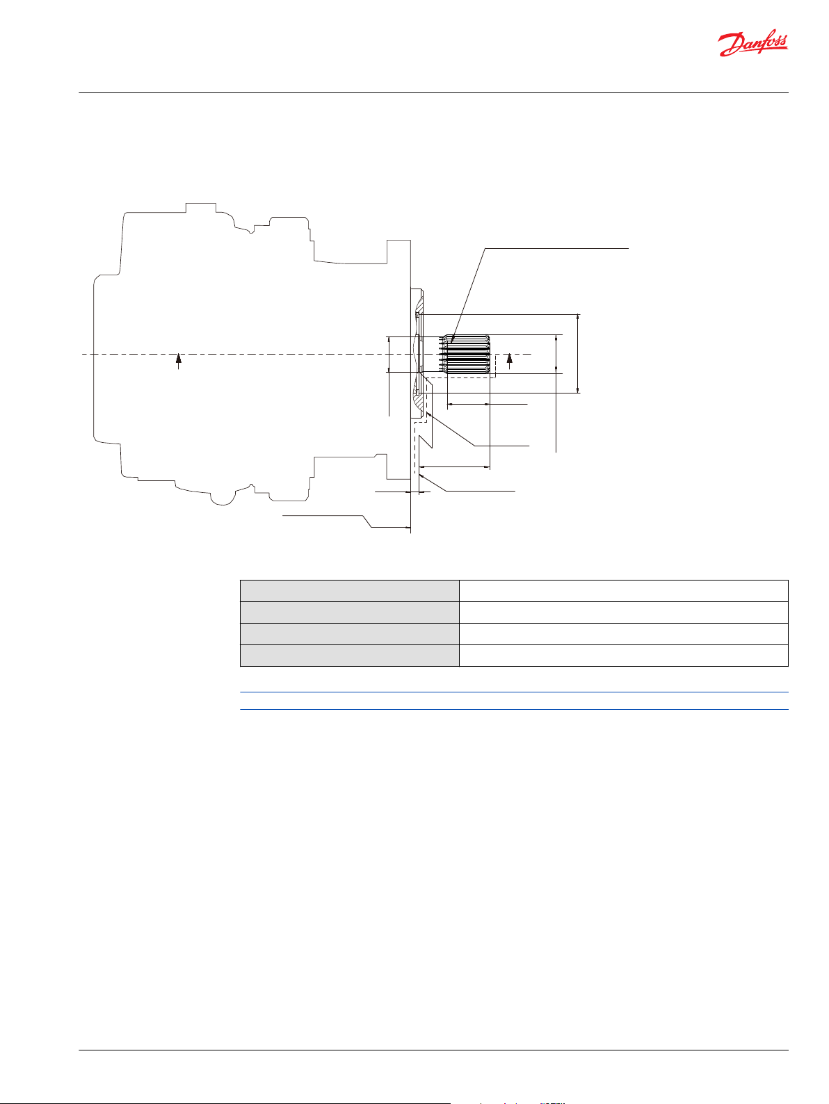
P400334
AD
33.8 ± 0.5
6.85 ± 1
Paint free
63.5 ± 1.5
Mating coupling
must not protrude
beyond this point
Mounting flange
Flange 101-2
Per ISO 3019-1 (SAE B)
AD
Spline data
Number of teeth: 19
Pitch fraction: 16/32
Pressure angle: 30
°
Pitch dia: Ø30.163
Type of fit: Fillet root side
Per: ANSI B92.1-1970 Class 5
Ø 31.24± 0.09
27.7 ± 0.12
Ø72.3
Technical Information
MP1 Axial Piston Pumps Size 28/32, 38/45
Installation drawings
Input shafts: option G6, G7 (SAE B, 19 teeth)
Option G6, G7, ISO 3019-1, outer dia 31.24 mm (38/45 only)
Specifications
Option
Spline
Min. active spline length
1)
Maximum torque rating
1)
Minimum active spline length for the specified torque ratings.
G6, G7
19 teeth, 16/32 pitch
33.8 ± 0.5
734 N•m
Please contact Danfoss representative for specific installation drawings.
©
Danfoss | February 2022 BC178386485160en-000503 | 77
Page 78

P400335
AD
6.85 ± 1
Paint free
55 ± 0.8
78 ± 1.5
Mating coupling
must not protrude
beyond this point
Mounting flange
Flange 101-2
Per ISO 3019-1 (SAE B)
A
A-A
A
Ø 25.37
6.4
0
-0.2
21.82
0
-0.2
± 0.025
Ø72.3
Technical Information
MP1 Axial Piston Pumps Size 28/32, 38/45
Installation drawings
Input shafts: option A6, A8 (SAE B, straight key shaft)
Option A8, A6, ISO 3019-1, outer dia 1 inch (38/45 only)
Specifications
Option
Maximum torque rating
A6, A8
362 N•m
Please contact Danfoss representative for specific installation drawings.
78 | © Danfoss | February 2022 BC178386485160en-000503
Page 79

P400336
AD
6.85 ± 1
Paint
free
20.1 ± 0.7
3.2 ± 0.125
6.4 ± 0.05
26.97 ± 0.25
9.4 ± 0.38
Gauge
25-3 Taper per ISO 3019-1
3/4 - 16 UNF THD
8.3 ± 1.2
43 ± 1.5
Mating coupling
must not protrude
beyond this point
Mounting flange
Flange 101-2
Per ISO 3019-1 (SAE B)
A
A-A
A
Ø 22.2 Gauge
Ø72.3
C
Technical Information
MP1 Axial Piston Pumps Size 28/32, 38/45
Installation drawings
Input shafts: option F2, F3 (SAE B, taper key shaft)
Option F2, F3, ISO 3019-1, Code 25-3, Dia 22.2 Taper 1:8, without key, no through-hole in the end of the shaft (38/45 only)
Specifications
Option
Maximum torque rating
F2, F3
497 N•m
Please contact Danfoss representative for specific installation drawings.
Tapered shaft customer acknowledgement
The Danfoss MP1 tapered shaft has been designed using the industry standard ISO 3019-1, minus the
through-hole in the end of the shaft. Danfoss recommends a self-locking nut instead of a castle nut and
pin. The nut and mating square-cut key are customer supplied.
The specified torque rating of the tapered shaft documented above is based on the cross-sectional
diameter of the shaft, through the keyway, and assumes the proper clamp and fit between shaft and
coupling. Danfoss guarantees the design and manufactured quality of the tapered shaft. The customer is
responsible for the design and manufactured quality of the mating female coupling and key and applied
torque on the nut. Danfoss has made provisions for the key in accordance to the ISO specification with
the understanding that the key is solely to assist in the installation of the mating coupling.
Caution
Torque must be transmitted by the taper fit between the shaft and it’s mating coupling, not the key.
failure.
Torque or loading inadvertently transmitted by the customer supplied key may lead to premature shaft
©
Danfoss | February 2022 BC178386485160en-000503 | 79
Page 80

P400324
2x 53.2 ± 0.175
2x 106.4 ± 0.35
4x M10 x1.5-6H THD
15min THD depth
Ø88.621
Ref Ø82.22 ID x
2.62 cross section
+0.13
0
Ø82.601
+0.076
0
“A” ± 2.5
Auxiliary mounting pad
For mating flange 82-2
Per ISO 3019-1 (SAE A)
Paint free
R0.8 max
1.956 ± 0.076
8.1 ± 0.25
Shaft clearance
Shaft clearance
Mating shaft must not
protrude beyond this poit
Mating shaft shoulder must not
protrude beyond this poit
Spline data
Number of teeth: 9
Pitch fraction: 16/32
Pressure angle: 30
°
Pitch dia: Ø14.288
Type of fit: Fillet root side
Per: ANSI B92.1-1970 Class 7
“B”
“C”
Danfoss part number 9004104-1520
Technical Information
MP1 Axial Piston Pumps Size 28/32, 38/45
Installation drawings
Auxiliary mounting: option A16, B16, C16, D16, E16, F16 (SAE A, 9 teeth)
Option A16, B16, C16, D16, E16, F16, ISO 3019-1, flange 82-2 (SAE A, 9 teeth)
Location 28/32 38/45
A 210 234.5
B 11.8 min shaft clearance 12.0 min shaft clearance
C 38.3 min shaft clearance 50.0 min shaft clearance
Specifications
Option
Spline
Maximum torque
80 | © Danfoss | February 2022 BC178386485160en-000503
A16, B16, C16, D16, E16, F16
9 teeth, 16/32 pitch
107 N•m
Page 81

P400325
2x 53.2 ± 0.175
2x 106.4 ± 0.35
4x M10 x1.5-6H THD
15min THD depth
Ø88.621
Ref Ø82.22 ID x
2.62 cross section
+0.13
0
Ø82.601
+0.076
0
“A” ± 2.5
Auxiliary mounting pad
For mating flange 82-2
Per ISO 3019-1 (SAE A)
Paint free
R0.8 max
1.956 ± 0.076
8.1 ± 0.25
Shaft clearance
Shaft clearance
Mating shaft must not
protrude beyond this poit
Mating shaft shoulder must not
protrude beyond this poit
Spline data
Number of teeth: 11
Pitch fraction: 16/32
Pressure angle: 30
°
Pitch dia: Ø17.463
Type of fit: Fillet root side
Per: ANSI B92.1-1970 Class 7
“B”
“C”
Danfoss part number 9004104-1520
Technical Information
MP1 Axial Piston Pumps Size 28/32, 38/45
Installation drawings
Auxiliary mounting: option A19, B19, C19, D19, E19, F19 (SAE A, 11 teeth)
Option A19, B19, C19, D19, E19, F19, ISO 3019-1, flange 82-2 (SAE A, 11 teeth)
Location 28/32 38/45
A 210 234.5
B 11.8 min shaft clearance 12.0 min shaft clearance
C 38.3 min shaft clearance 50.0 min shaft clearance
Specifications
Option
Spline
Maximum torque
©
Danfoss | February 2022 BC178386485160en-000503 | 81
A19, B19, C19, D19, E19, F19
11 teeth, 16/32 pitch
147 N•m
Page 82

P400326
2x73 ± 0.175
2x 146 ± 0.35
4x M12 x1.75-6H THD
21.4 min THD depth
Ø107.823
Ref Ø94.92 ID x
2.62 cross section
+0.13
0
Ø101.651
+0.076
0
Auxiliary mounting pad
For mating flange 101-2
Per ISO 3019-1 (SAE B)
R0.8 max
1.956 ± 0.076
11.4 ± 0.25
Shaft clearance
Shaft clearance
Paint free
“A” ± 2.5
Mating shaft must not
protrude beyond this poit
Mating shaft shoulder must not
protrude beyond this poit
Spline data
Number of teeth: 13
Pitch fraction: 16/32
Pressure angle: 30
°
Pitch dia: Ø20.638
Type of fit: Fillet root side
Per: ANSI B92.1-1970 Class 7
“B”
“C”
Danfoss part number 9004104-1540
Technical Information
MP1 Axial Piston Pumps Size 28/32, 38/45
Installation drawings
Auxiliary mounting: option A22, B22, C22, D22, E22, F22 (SAE B, 13 teeth)
Option A22, B22, C22, D22, E22, F22, ISO 3019-1, flange 101-2 (SAE B, 13 teeth)
Location 28/32 38/45
A 213 234.5
B 14.8 min shaft clearance 12.0 min shaft clearance
C 41.3 min shaft clearance 50.0 min shaft clearance
Specifications
Option
Spline
Maximum torque
Bolt length greater than 21.4 mm could result in a leak or damage the unit.
82 | © Danfoss | February 2022 BC178386485160en-000503
A22, B22, C22, D22, E22, F22
13 teeth, 16/32 pitch
248 N•m
Page 83

P400337
2x73 ± 0.175
2x 146 ± 0.35
4x M12 x1.75-6H THD
21.4 min THD depth
Ø107.823
Ref Ø94.92 ID x
2.62 cross section
+0.13
0
Ø101.651
+0.076
0
Auxiliary mounting pad
For mating flange 101-2
Per ISO 3019-1 (SAE B-B)
R0.8 max
1.96 ± 0.08
11.4 ± 0.25
Shaft clearance
Paint free
“A” ± 2.5
Mating shaft shoulder must not
protrude beyond this poit
Mating shaft shoulder must not
protrude beyond this poit
Spline data
Number of teeth: 15
Pitch fraction: 16/32
Pressure angle: 30
°
Pitch dia: Ø23.813
Type of fit: Fillet root side
Per: ANSI B92.1b-1996 Class 7e
“B”
Shaft clearance
“C”
Danfoss part number 9004104-1540
Technical Information
MP1 Axial Piston Pumps Size 28/32, 38/45
Installation drawings
Auxiliary mounting: option A25, B25, C25, D25, E25, F25 (SAE B-B 15 teeth)
Option A25, B25, C25, D25, E25, F25, ISO 3019-1, flange 101-2 (SAE B-B, 15 teeth) (38/45 only)
Location 38/45
A 234.5
B 12.0 min shaft clearance
C 50.0 min shaft clearance
Specifications
Option
Spline
Maximum torque
Bolt length greater than 21.4 mm could result in a leak or damage the unit.
©
Danfoss | February 2022 BC178386485160en-000503 | 83
A25, B25, C25, D25, E25, F25
15 teeth, 16/32 pitch
347 N•m
Page 84

P400314
Control Manual Override “C1”
Case Gauge Port “M14”
Shaft
Z (2:1)
2x
1
2
Shaft
Mounting Flange
Mounting Flange
Depressing the plunger mechanically
moves the control spool. Actucation
allows full stroke pump respose as per coil
and rotation dependent control logic.
Control Manual Override “C2”
Z
Control Solenoid
Connector “C1”
Deutsch DT04-2P
Paint free
Control Solenoid
Connector “C2”
Deutsch DT04-2P
Paint free
Depressing the plunger mechanically
moves the control spool. Actucation
allows full stroke pump respose as per coil
and rotation dependent control logic.
“D” ±0.8
“B” ±1.2
2x 64.2±0.8
206±2.5
“C” ±2.5
“A” ±1.2
Ø21 max clearance dia for fitting
Technical Information
MP1 Axial Piston Pumps Size 28/32, 38/45
Controls
Electric displacement control (EDC)
Control solenoid connector “C1” & “C2”
Pin Assignment OR Pin Assignment
1 Supply 1 Ground
2 Ground 2 Supply
Location 28/32 38/45
A 142.3 143.8
B 120.5 117
C 168.3 169.8
D 58.4 54.9
Please contact Danfoss representative for specific installation drawings.
84 | © Danfoss | February 2022 BC178386485160en-000503
Page 85

Control Manual Override “
C1
”
Case Gauge Port “M14”
Ø21 max clearance dia for fitting
Z (2:1)
2x
Y (2:1)
Control Solenoid
Connector “C1”
Deutsch DT04-2P
Paint free
Control Cut-Off
Connector “C4”
Deutsch DT04-2PC
Paint free
Control Solenoid
Connector “C2”
Deutsch DT04-2P
Paint free
Depressing the plunger mechanically
moves the control spool. Actuation
allows full stroke pump response as per coil and
rotation dependent control logic.
Shaft
1
2
1
2
Mounting flange
“D”± 0.8
“F”± 1.2
“B”± 1.2
Y
Z
“G”± 2.5
Control Manual Override “C2”
Depressing the plunger mechanically
moves the control spool. Actuation
allows full stroke pump response as
per coil and rotation dependent
control logic.
2x 64.2 ± 0.839.5 ± 0.8
206 ± 2.5
“C” ± 2.5
“E” ± 1.2
“A” ± 1.2
Mounting flange
P400331
Shaft
Hydraulic logic Port” “ X7
“J ” ± 0.5
“H”± 0.8
Technical Information
MP1 Axial Piston Pumps Size 28/32, 38/45
Controls
Electric displacement control with CCO (EDC+CCO)
©
Danfoss | February 2022 BC178386485160en-000503 | 85
Control solenoid connector “C1” & “C2” & "C4"
Pin Assignment OR Pin Assignment
1 Supply 1 Ground
2 Ground 2 Supply
Location 28/32 38/45
A 142.3 143.8
B 120.5 117
C 169.6 171.4
D 58.4 54.9
E 152.3 153.8
F 139.8 136.3
G 181.4 178
H 110.2 106.7
J 6.5
Please contact Danfoss representative for specific installation drawings.
Page 86

1
1
2
2
3
4
F
Y
Y
2x 64.2 ±0.8
206.2 ±0.8
±2.5
±2.5
±1.2
X
X
14.5 ±1
±1.2
±1.5
±0.8
E
D
C
A
B
Control solenoid
connector “C1”
DEUTSCH DT04-2P
Paint free
Control solenoid
connector “C2”
DEUTSCH DT04-2P
Paint free
Angle sensor connector
DEUTSCH DTM04-4P
Paint free
Mounting flange
Shaft
Shaft
Mounting flange
Technical Information
MP1 Axial Piston Pumps Size 28/32, 38/45
Controls
EDC with ASNSR
Control solenoid connector “C1” & “C2”
Pin Assignment OR Pin Assignment
1 Supply 1 Ground
2 Ground 2 Supply
Angle sensor connector pinout
Pin Assignment
1 Ground (GND)
2 Not connected
3 Output signal 1 (SIG 1)
4 Supply (V+)
Dimensions
Reference 28/32 38/45
A 32.7 29.2
B 120.5 117
C 142.3 143.8
D 169.6 171.4
E 193.3 194.8
F 58.4 54.9
86 | © Danfoss | February 2022 BC178386485160en-000503
Page 87
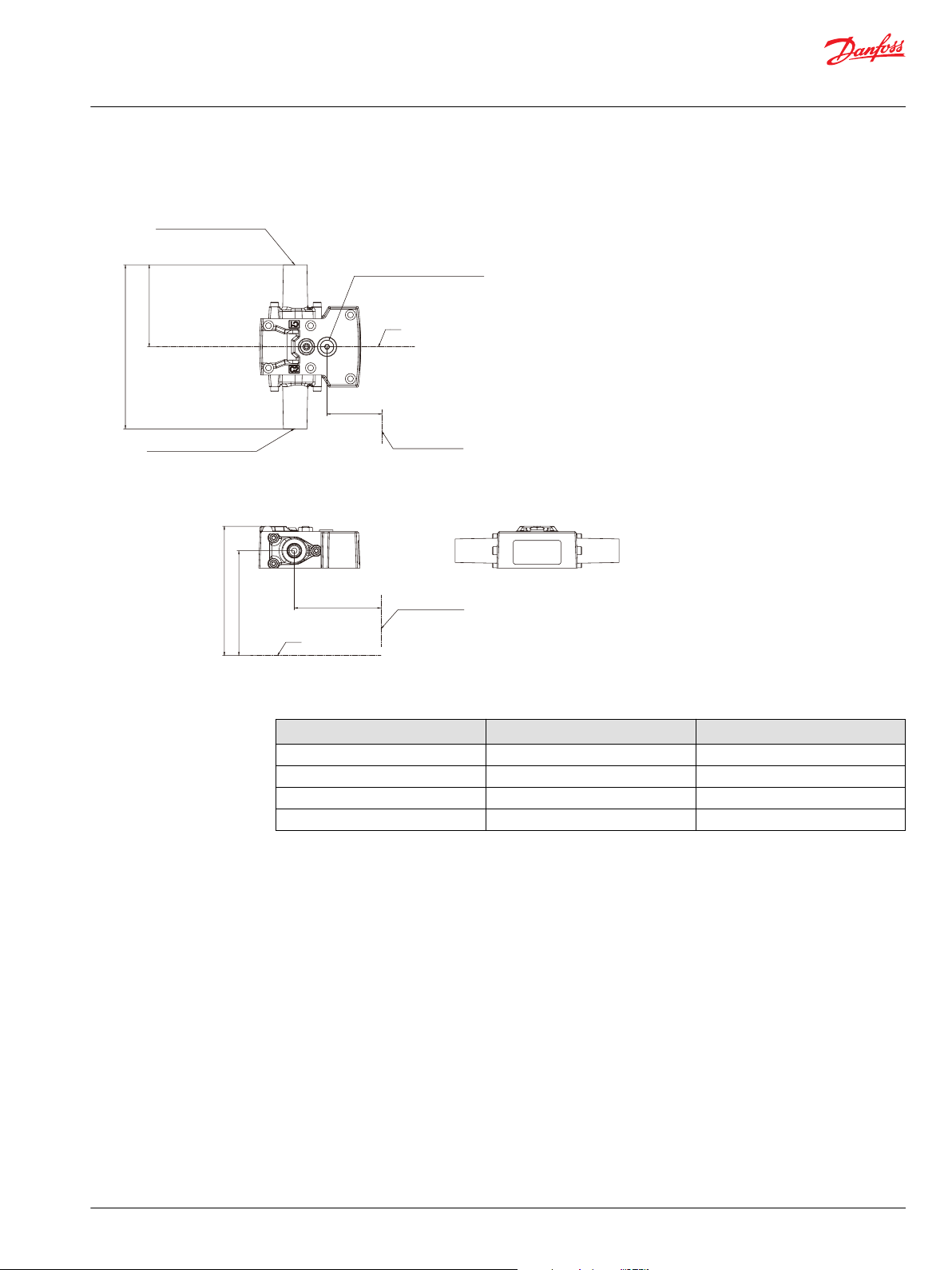
Shaft
Shaft
Ø21 max clearance dia for fitting
Inch = ISO 11926-1 9/16-18
Metric = ISO 6149-1 M14x1.5
Inch = ISO 11926-1 9/16-18
Metric = ISO 6149-1 M14x1.5
174.8
2x 87.4 ± 0.8
Hydraulic Port
“X1” & “X2”
± 2.5
Mounting flange
Mounting flange
P400518
Hydraulic Signal Port “X1”
Hydraulic Signal Port “ X2”
“D” ± 0.8
“B” ± 0.8
“C” ± 2.5
“A” ± 1.2
Case Gauge Port “M14”
Technical Information
MP1 Axial Piston Pumps Size 28/32, 38/45
Controls
Hydraulic displacement control (HDC)
Legend
Dimension 28/32 38/45
A 142.3 143.8
B 92.4 88.9
C 168.3 169.8
D 58.4 54.9
©
Danfoss | February 2022 BC178386485160en-000503 | 87
Page 88
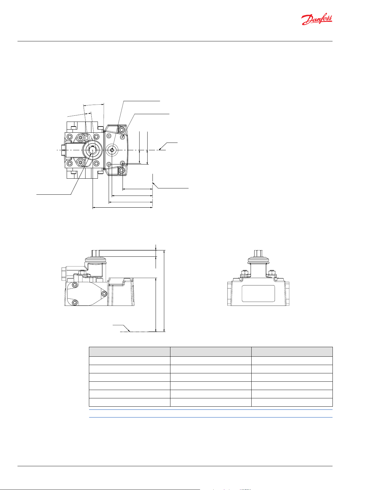
Shaft
“A” ±1.2
“B” ±2.5
9.8
+1
0
P400315
Mounting flange
“C” ±0.8
“D” ±0.8
“E” ±0.8
“F” ±0.8
2x22±0.5
2x24±0.8
4x M6x1-6H Thd
9 min full thd. depth
paint free
Case gauge port “M14“
7.5±1°
3x11
-0.02
-0.08
Shaft
Control Handle Shaft
Technical Information
MP1 Axial Piston Pumps Size 28/32, 38/45
Controls
Manual displacement control (MDC)
Location 28/32 38/45
A 166.8 168.3
B 209.7 211.2
C 31.9 28.4
D 49.7 46.2
E 54.9 51.4
F 82.3 78.8
Please contact Danfoss representative for specific installation drawings.
88 | © Danfoss | February 2022 BC178386485160en-000503
Page 89

Mounting flange
2x22±0.5
2x24±0.5
7.5±1°
3x11
-0.02
-0.08
4x M6x1-6H thd.
9 min. full thd. depth
paint free
Neutral Start Switch connector
DEUTSCH DT04-2P
paint free
Case gauge port M14
ISO 11926-1 -7/16-20
Shaft
Control handle shaft
Shaft
9.8
+1
0
C ±0.8
D ±0.8
E ±0.8
F ±0.8
B ±2.5
A ±1.2
Technical Information
MP1 Axial Piston Pumps Size 28/32, 38/45
Controls
MP1 MDC with neutral start switch option: M2
Neutral start switch connector
Pin Assignment Alternate Pin Assignment
1 Supply OR 1 Ground
2 Ground 2 Supply
Dimension 28/32 38/45
A 166.8 168.3
B 209.7 211.2
C 31.9 28.4
D 49.7 46.2
E 54.9 51.4
F 82.3 78.8
Please contact Danfoss representative for specific installation drawings.
©
Danfoss | February 2022 BC178386485160en-000503 | 89
Page 90

Mounting flange
98.8 ±1.5
2x22±0.5
9.8
+1
2x24±0.5
7.5±1°
3x11
-0.02
-0.08
4x M6x1-6H thd.
9 min. full thd. depth
paint free
Shaft
Control handle shaft
Shaft
0
Control Cut Off connector C4
DEUTSCH DT04-2P
paint free
Control Cut Off connector C4
DEUTSCH DT04-2P
paint free
Case gauge port M14
ISO 11926-1 -7/16-20
Brake gauge port X7
ISO 11926-1 -7/16-20
72.15±0.8
C ±0.8
D ±0.8
E ±0.8
F ±1.2
B ±2.5
A ±1.2
Technical Information
MP1 Axial Piston Pumps Size 28/32, 38/45
Controls
MP1 MDC with CCO, options: M3, M4
Control cut off connector (C4)
Pin Assignment Alternate Pin Assignment
1 Supply OR 1 Ground
2 Ground 2 Supply
Dimension 28/32 38/45
A 166.8 168.3
B 209.7 211.2
C 31.9 28.4
D 49.7 46.2
E 54.9 51.4
90 | © Danfoss | February 2022 BC178386485160en-000503
F 82.3 78.8
Please contact Danfoss representative for specific installation drawings.
Page 91

Mounting flange
2x22±0.5
2x24±0.5
7.5±1°
3x11
-0.02
-0.08
4x M6x1-6H thd.
9 min. full thd. depth
paint free
Neutral Start Switch connector
DEUTSCH DT04-2P
paint free
Case gauge port M14
ISO 11926-1 -7/16-20
Shaft
Control handle shaft
Shaft
9.6
+1
0
Control Cut Off connector C4
DEUTSCH DT04-2P
paint free
Brake gauge port X7
ISO 11926-1 -7/16-20
72.15 ±0.8
98.8 ±1.5
Control Cut Off connector C4
DEUTSCH DT04-2P
paint free
C ±0.8
D ±0.8
E ±0.8
F ±1.2
B ±2.5
A ±1.2
Technical Information
MP1 Axial Piston Pumps Size 28/32, 38/45
Controls
MP1 MDC with NSS and CCO options: M5, M6
Neutral start switch, control cut off connectors
Pin Assignment Alternate Pin Assignment
1 Supply OR 1 Ground
2 Ground 2 Supply
Dimension 28/32 38/45
A 166.8 168.3
©
Danfoss | February 2022 BC178386485160en-000503 | 91
B 209.7 211.2
C 31.9 28.4
D 49.7 46.2
E 54.9 51.4
F 82.3 78.8
Please contact Danfoss representative for specific installation drawings.
Page 92

P400316
Control Manual Override “C1”
Case Gauge Port “M14”
Shaft
Z (2:1)
2x
1
2
Shaft
Mounting Flange
Mounting Flange
Depressing the plunger mechanically
moves the control spool. Actucation
allows full stroke pump respose as per coil
and rotation dependent control logic.
Control Manual Override “C2”
Z
Control Solenoid
Connector “C1”
Deutsch DT04-2P
Paint free
Control Solenoid
Connector “C2”
Deutsch DT04-2P
Paint free
Depressing the plunger mechanically
moves the control spool. Actucation
allows full stroke pump respose as per coil
and rotation dependent control logic.
“D” ±0.8
“B” ±1.2
2x 64.2±0.8
206±2.5
“C” ±2.5
“A” ±1.2
Ø21 max clearance dia for fitting
Technical Information
MP1 Axial Piston Pumps Size 28/32, 38/45
Controls
Forward-neutral-reverse (FNR)
Control solenoid connector “C1” & “C2”
Pin Assignment OR Pin Assignment
1 Supply 1 Ground
2 Ground 2 Supply
Dimension 28/32 38/45
A 142.3 143.8
B 120.5 117
C 168.3 169.8
D 58.4 54.9
Please contact Danfoss representative for specific installation drawings.
92 | © Danfoss | February 2022 BC178386485160en-000503
Page 93

Control manual override C2
Depressing the plunger mechanically
moves the control spool. Actuation
allows full stroke pump response as
per coil and rotation dependent
control logic
Control manual override C1
Depressing the plunger mechanically
moves the control spool. Actuation
allows full stroke pump response as
per coil and rotation dependent
control logic
Mounting flange
Shaft
2x 64.2 ±0.8
206 ±2.5
Shaft
Control solenoid
connector C1
Deutsch DT04-2P
paint free
Control solenoid
connector C1
Deutsch DT04-2P
paint free
Case gauge port M14
Port ISO 1926-1 - 7/16-20
∅21 max clearance dia for fitting
Z
C
L
C
L
Mounting flange
B ±1.2
C ±2.5
A ±1.2
D ±0.8
Technical Information
MP1 Axial Piston Pumps Size 28/32, 38/45
Controls
Non-feedback proportional electric (NFPE)
Control solenoid xonnector “C1” & “C2”
Pin Assignment OR Pin Assignment
1 Supply 1 Ground
2 Ground 2 Supply
Dimension 28/32 38/45
A 142.3 143.8
B 120.5 117
C 168.3 169.8
D 58.4 54.9
Please contact Danfoss representative for specific installation drawings.
©
Danfoss | February 2022 BC178386485160en-000503 | 93
Page 94

Shaft
C ± 2.5
2x A ± 1.2
Servo pressure supply port X2
Port ISO 11926-1 - 9/16-8
2x B ± 1.2
Mounting flange
Shaft
Servo pressure supply port X1
Port ISO 11926-1 - 9/16-18
Shaft
2x 30 ± 0.8
Section A-A
Technical Information
MP1 Axial Piston Pumps Size 28/32, 38/45
Controls
MP1 Non-feedback proportional hydraulic (NFPH)
Dimension 28/32 38/45
A 145.3 146.8
B 96.4 92.9
C 168.3 169.8
94 | © Danfoss | February 2022 BC178386485160en-000503
Page 95

61.2 ±0.8 61.2 ±0.8
30.2
±
0.8
C1
CAN
CC2
CC2
C2
V
209 max
V
2
CAN
CC1
CC2
CCC3
CCC3
220 ±2.5
110 ±1.5
1
Technical Information
MP1 Axial Piston Pumps Size 28/32, 38/45
Controls
Automotive control (AC)
1 Plug removing can cause contamination issues
2 PPU wire harness is factory installed to speed sensor
Connectors description
Port Description
C1 and C2
1. Control manual override C1
2. Control Manual Override C2
CC1
CC2
CC3
CAN
Port A control connector DEUTSCH DTM04-12P; paint free
Port B control connector DEUTSCH DTM04-12P; paint free
Control connector DEUTSCH DT06-2S; paint free; For using connector, the plug may be removed.
Control connector DEUTSCH DTM04-3P; paint free; For using connector, the plug may be removed.
Please contact Danfoss representative for specific installation drawings.
©
Danfoss | February 2022 BC178386485160en-000503 | 95
Page 96

CC3
CC3
PPC
CAN
C1
C2
PPU
CC2
CC1
CAN
PPC
CC2
206 ±2.5
2x 61.2 ±0.8
30.2 ±0.8
9.6 ±0.8
74.5 ±0.1
2
1
1 2 3
1
2
3
6
5
4
1 2 3 4 5 6
12
11
10
9 8 7
Technical Information
MP1 Axial Piston Pumps Size 28/32, 38/45
Controls
AC connectors dimensions
PPU wire harness is factory installed to speed sensor.
CC3 CAN PPC
Connector DEUTSCH, 2-pin
1. Digital output A1 (+)
2. Digital output A2 (-)
Connector DEUTSCH, 12-pin
Connector DEUTSCH, 3-pin
1. CAN High
2. CAN Low
3. CAN Shield
CC1
1. Battery (-)
2. Battery (+)
3. Sensor (+)
4. Sensor (-)
5. Motor rpm input (frequency)
6. Forward input (digital)
7. Reverse input (digital)
8. Sensor (+)
9. Sensor (-)
10. Drive pedal input (analog –
nominal)
11. Drive pedal input (analog – red)
12. Neural input (digital)
Connector DEUTSCH, 6-pin
1. Sensor A (+)
2. Analog input A
3. Sensor A (-)
4. Sensor B (-)
5. Analog input B
6. Sensor B (+)
CC2
1. Inch input (analog – red)
2. Mode switch B input (digital –
nominal)
3. Motor prop/PCOR driver
4. Motor direction input (analog)
5. Sensor (+)
6. Sensor (-)
7. Inch input (analog – nominal)
8. Motor BPD driver
9. Digital output B2 (-)
10. Digital output B1 (+)
11. Mode switch A input (digital)
12. Mode switch B input (digital – red)
96 | © Danfoss | February 2022 BC178386485160en-000503
Page 97

P400328
“F” (plugged)
“E” (plugged)
Charge gauge port “M3”
Charge inlet port “S”
Inch : 1 1/16-12
Metric : M27x2
“F” (plugged)
“E” (plugged)
Charge inlet port “S”
Inch : 1 5/16-12
Metric : M33x2
P400338
Technical Information
MP1 Axial Piston Pumps Size 28/32, 38/45
Filtration
Suction filtration: option S
28/32
38/45
Please contact Danfoss representative for specific installation drawings.
Please contact Danfoss representative for specific installation drawings.
©
Danfoss | February 2022 BC178386485160en-000503 | 97
Page 98

Charge filtration port “F”
(to filter)
Inch: 9/16-18
Metric: M14x1.5
Charge filtration port “E”
(from filter)
Inch: 9/16-18
Metric: M14x1.5
Inch : 1 1/16-12
Metric : M27x2
Charge inlet port “S”
Shaft
C - C / D - D
108.5 ± 0.4
D D
C C
Charge gauge port “
M3”
Shaft
C - C / D - D
122.6 ± 0.4
D D
C C
Charge filtration port “
F”
(to filter)
Inch: 9/16-18
Metric: M14x1.5
Charge filtration port “
E”
(from filter)
Inch: 9/16-18
Metric: M14x1.5
Inch: 1 5/16-12
Metric: M33x2
Charge inlet port “
S”
P400339
Technical Information
MP1 Axial Piston Pumps Size 28/32, 38/45
Filtration
Remote full flow charge pressure filtration: option R
28/32
38/45
Please contact Danfoss representative for specific installation drawings.
Please contact Danfoss representative for specific installation drawings.
98 | © Danfoss | February 2022 BC178386485160en-000503
Page 99

“F” (plugged)
External charge
Inch : 9/16-18
Metric : M14x1.5
inlet port “
E
”
“S” (plugged)
C - C
Shaft
108.5 ± 0.4
C C
Charge gauge port “M3”
P400330
C - C
Shaft
122.6 ± 0.4
C C
“F” (plugged)
External charge
Inch : 9/16-18
Metric : M14x1.5
inlet port “
E”
“S” (plugged)
P400340
Technical Information
MP1 Axial Piston Pumps Size 28/32, 38/45
Filtration
External full flow charge pressure filtration: option E
28/32
Please contact Danfoss representative for specific installation drawings.
38/45
Please contact Danfoss representative for specific installation drawings.
©
Danfoss | February 2022 BC178386485160en-000503 | 99
Page 100

Danfoss
Power Solutions GmbH & Co. OHG
Krokamp 35
D-24539 Neumünster, Germany
Phone: +49 4321 871 0
Danfoss
Power Solutions ApS
Nordborgvej 81
DK-6430 Nordborg, Denmark
Phone: +45 7488 2222
Danfoss
Power Solutions (US) Company
2800 East 13th Street
Ames, IA 50010, USA
Phone: +1 515 239 6000
Danfoss
Power Solutions Trading
(Shanghai) Co., Ltd.
Building #22, No. 1000 Jin Hai Rd
Jin Qiao, Pudong New District
Shanghai, China 201206
Phone: +86 21 2080 6201
Products we offer:
Hydro-Gear
www.hydro-gear.com
Daikin-Sauer-Danfoss
www.daikin-sauer-danfoss.com
Cartridge valves
•
DCV directional control
•
valves
Electric converters
•
Electric machines
•
Electric motors
•
Gear motors
•
Gear pumps
•
Hydraulic integrated
•
circuits (HICs)
Hydrostatic motors
•
Hydrostatic pumps
•
Orbital motors
•
PLUS+1® controllers
•
PLUS+1® displays
•
PLUS+1® joysticks and
•
pedals
PLUS+1® operator
•
interfaces
PLUS+1® sensors
•
PLUS+1® software
•
PLUS+1® software services,
•
support and training
Position controls and
•
sensors
PVG proportional valves
•
Steering components and
•
systems
Telematics
•
Danfoss Power Solutions is a global manufacturer and supplier of high-quality hydraulic and
electric components. We specialize in providing state-of-the-art technology and solutions
that excel in the harsh operating conditions of the mobile off-highway market as well as the
marine sector. Building on our extensive applications expertise, we work closely with you to
ensure exceptional performance for a broad range of applications. We help you and other
customers around the world speed up system development, reduce costs and bring vehicles
and vessels to market faster.
Danfoss Power Solutions – your strongest partner in mobile hydraulics and mobile
electrification.
Go to www.danfoss.com for further product information.
We offer you expert worldwide support for ensuring the best possible solutions for
outstanding performance. And with an extensive network of Global Service Partners, we also
provide you with comprehensive global service for all of our components.
Local address:
Danfoss can accept no responsibility for possible errors in catalogues, brochures and other printed material. Danfoss reserves the right to alter its products without notice. This also applies to products
already on order provided that such alterations can be made without subsequent changes being necessary in specifications already agreed.
All trademarks in this material are property of the respective companies. Danfoss and the Danfoss logotype are trademarks of Danfoss A/S. All rights reserved.
©
Danfoss | February 2022 BC178386485160en-000503
 Loading...