

Page 1
User guide
Modbus RTU Module
for heat meter SonoMeter 30
Applications
Features
Power supply
Communication interface
The Modbus RTU module is destined to heat
meters in order the heat meters to Modbus RTU
network using EIA-485 channel.
• Galvanic isolation EIA-485 network interface used for easy and safe connection up to 256 devices
in one network bus.
• Modbus RTU Slave protocol is realized according to specifications by Modbus Organization.
Polarity independent connection for SELV power supply – connectors 60 and 61
Voltage: 12-24 V(AC/DC)
Maximum power consumption: 2 W max.
Typical supply current: 50 mA
Connectors 90 (noninverting, +) and 91 (inverting, -)
Communication protocol Modbus RTU
Baud rate (bits per second) 1200, 2400, 4800, 9600-default,19200,38400, 56000, 57600, 115200
Data format8E1
(8 data bits, even parit y bit, 1 stop bit)-default
8O1 (8 data bits, odd parity bit, 1 stop bit)
8N2 (8 data bits, none parity bit, 2 stop bits)
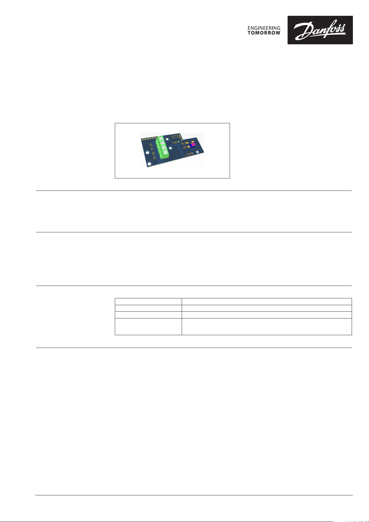
Status LED and Status
Button functionality
© Danfoss | 2018.02 BC262356385429en-000101 | 1
Status LED is signalizing every Modbus communication event. Status LED is blinking on during
request and response sending.
Press the button, then power on the module and hold the button pushed longer than 15seconds to
reset device to factory settings (set Modbus Slave ID todefault value 1, the Update Rate parameter to
default 10 minutes and the communication interface to defaults parameters –9600 bps baud rate and
8E1 data format).
Page 2
User guide Modbuster RTU module for SonoMeter 30
Modbus RTU Module for
heat meters
Parameters which can be changed:
• ModBus address (Slave ID);
• Update Rate Data from Meter;
• Baud Rate
• Parity
• Stop Bits
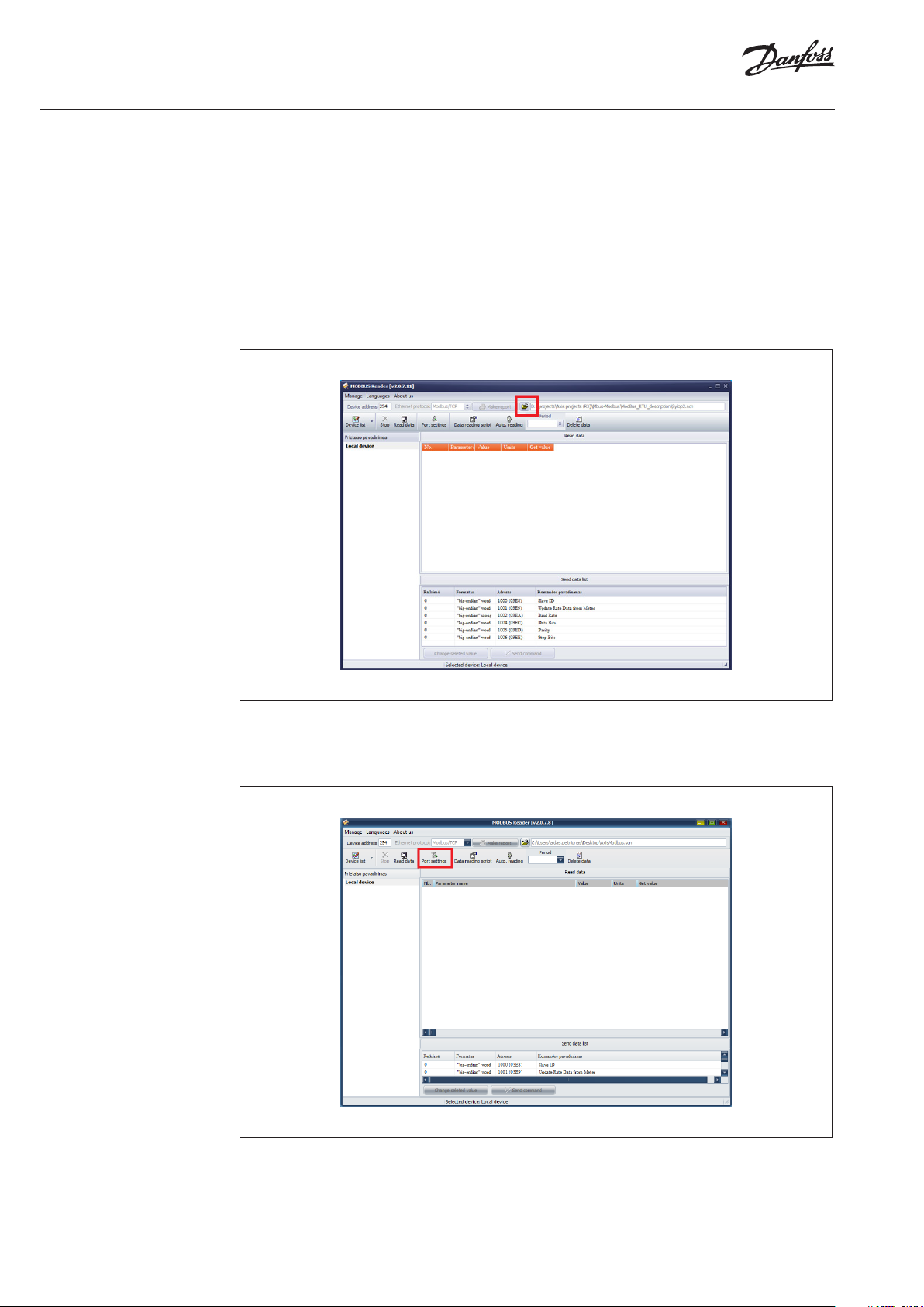
Parameters can be changed using software called “Modbus Reader”.
1. First of all you need to open attached reading scenario called “Modbus.scn”. When it is opened,
the main window which present in.
Fig 1 will be seen.
2. Then change device address, default is “1”.
3. Then click “Port Settings”.
2 | BC262356385429en-000101 © Danfoss | 2018.02
Page 3
User guide Modbuster RTU module for SonoMeter 30
Modbus RTU Module for
heat meters (continuo us)
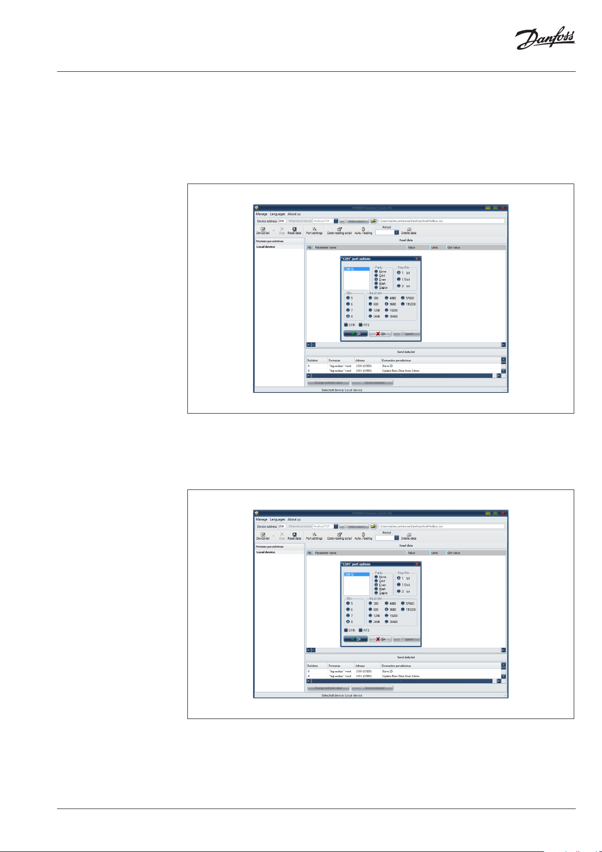
4. Then immediately opens new window. In that new window choose the correctly parameters to
read device.
• Parity – “Even”
• Stop Bits – “1 bit”
• Bits – “8”
• Baud rate – “9600 (default)”
Then click “Ok”
5. Read the actual Modbus card.
6. In the value column near the parameter which you want to change simply enter the changeable
value ant then press the button “Send command”. After this the parameter will be changed. In
order to read Modbus card again you have to change “Port settings” or “Device address” if it has
been changed.
7. If you need reset the ModBus module, you need to turn off the power supply from the 230V. Wait
when the module discharge (about 5-10sec) and hold on the module “set” button then plug in
230V. You need to hold on the button until “LINK” led blinked. After all, the ModBus address back
to default address.
BC262356385429en-000101 | 3© Danfoss | 2018.02
Page 4

User guide Modbuster RTU module for SonoMeter 30
Modbus data register list
Designation Modbus Register
Modbus Register
Typ e
Modbus
Address
Data Value
Range
Unit
Read only
(RO) Read/
write (R /W)
Heating Energy 30001 or 40001 Input or Holding 0 Int32 - RO
Heating Energy (Unit
factor)
30003 or 40003 Input or Holding 2 Uln t16 - RO
Heating Energy (Unit) 30004 or 40004 Input or Holding 3 4 char ASCII - RO
Heating Energy (Float) 30006 or 40006 Input or Holding 5 IEEE754 kWh, k J RO
Cooling Energy 30008 or 40008 Input or Holding 7 Int32 - RO
Cooling Energy (Unit
factor)
30010 or 40 010 Input or Holding 9 Ul nt16 - RO
Cooling Energy (Unit) 30 011 or 40 011 Input or Holding 10 4 char ASCII - RO
Cooling Energy (Float) 30 013 or 40013 Input or Holding 12 IEEE754 kWh, k J RO
Tariff Energy 1 30015 o r 40 015 Input or Holding 14 Int32 - RO
Tariff Energy 1 (Unit
factor)
30 017 or 4 0017 Input or Holding 16 Ulnt16 - RO
Tariff Energy 1 (Unit) 30018 or 40018 Input or Holding 17 4 char ASCII - RO
Tariff Energy 1 (Float) 30020 or 40020 Input or Holding 19 IEEE754 kWh, k J RO
Tariff Energy 2 30022 o r 40022 Input or Holding 21 Int32 - RO
Tariff Energy 2 (Unit
factor)
30024 or 40024 Input or Holding 23 Ulnt16 - RO
Tariff Energy 2 (Unit) 30025 or 40025 Input or Holding 24 4 char ASCII - RO
Tariff Energy 2 (Float) 30027 or 40 027 Input or Holding 26 IEEE754 kWh, k J RO
Volume 30029 or 40029 Input or Holding 28 Int32 - RO
Volume (Unit factor) 30 031 or 40 031 Input or Holding 30 Ulnt16 - RO
Volume (Unit) 30032 o r 40032 Input or Holding 31 4 char ASCII - RO
Volume (Float) 30034 or 40034 Input or Holding 33 IEEE754 m
3
RO
Pulse Input Volume 1 30036 or 40036 Input or Holding 35 Int32 - RO
Pulse Input Volume 1
(Unit factor)
Pulse Input Volume
1 (Unit)
Pulse Input Volume 1
(Float)
30038 or 40 038 Input or Holding 37 Ul nt16 - RO
30039 or 40039 Input or Holding 38 4 char ASCII - RO
30 041 or 4 0041 Input or Holding 40 IEEE754 m
3
RO
Pulse Input Volume 2 30043 or 400 43 Input or Holding 42 Int32 - RO
Pulse Input Volume 2
(Unit factor)
Pulse Input Volume
2 (Unit)
Pulse Input Volume 2
(Float)
30045 or 40045 Input or Holding 44 Ulnt16 - RO
30046 or 40046 Input or Holding 45 4 char ASCII - RO
30048 or 40048 Input or Holding 47 IEEE754 m
3
RO
Power 30050 or 40050 Input or Holding 49 Int 32 - RO
Power (Unit fac tor) 30052 or 40052 Input or Holding 51 Uln t16 - RO
Power (Unit) 30053 or 40 053 Input or Holding 52 4 char ASCII - RO
Power (Float) 30055 or 40055 Input or Holding 54 IEEE754 kW RO
Flow 30057 or 40057 Input or Holding 56 Int32 - RO
Flow (Unit fac tor) 30 059 or 40059 Input or Holding 58 Ulnt16 - RO
Flow (Unit) 30060 or 4 0060 Input or Holding 59 4 char ASCII - RO
Flow (Float) 30062 or 40062 Input or Holding 61 IEEE754 m3/h RO
Forward temperature
(Fixed)
Forward temperature
(Float)
Return temperature
(Fixed)
Return temperature
(Float)
Temperature
difference (Fixed)
Temperature
difference (Float)
Heat Meter Serial
Number (Fixed)
Heat Meter Serial
Number (ASCII)
30064 or 4006 4 Input or Holding 63 Int32 0 .001°C RO
30066 or 40066 Input or Holding 65 IEEE754 °C RO
30068 or 40068 Input or Holding 67 Int32 0.001°C RO
30070 or 40070 Input or Holding 69 IEEE754 °C RO
30072 o r 40072 Input or Holding 71 I nt32 0.0 01°C RO
30 074 or 40074 Input or Holding 73 IEEE754 °C RO
30076 or 40076 Input or Holding 75 Ulnt32 - RO
30078 or 40078 Input or Holding 77
8 char
ASCII
- RO
Error Code 30082 or 40 082 Input or Holding 81 Ulnt32 - RO
Module Serial Number 320 01 Input 2000 Ulnt32 - RO
4 | BC262356385429en-000101 © Danfoss | 2018.02
Page 5

User guide Modbuster RTU module for SonoMeter 30
Modbus data register list
(continuous)
Error codes meaning
Designation Modbus Register
Module Model
Number
Firmware Version
Modbus Slave ID
Update Rate Data
from Meter
1
2, 3
32003 Input 2002 Ulnt32 - RO
32005 Input 2004 Ulnt16 - RO
41001 Holding 1000 Ulnt16 - R/W
4100 2 Holding 1001 U lnt16 100 m s R/W
Modbus Register
Typ e
Modbus
Address
Data Value
Range
Unit
Read only
(RO) Read/
write (R /W)
Baud Rate 4100 3 Holding 1002 Ulnt32 - R/W
4
Data Bits
4, 5
Parity
4
Stop Bits
1
Higher byte of the register is major number of firmware version (0x##00). Lower byte of the register is minor number of
firmware version (0x00##).
2
Lower byte of this register is Modbus address of the module in range 1-247 (01-F7 hex).
3
If the higher byte is set to 1, the Modbus address will be updated to the meter M-Bus address. If the higher byte is set to
0, the Modbus address is static.
4
The registers should be set only the values represent data format on the EIA-485 serial interface described in chapter
Communication interface above.
5
This register is set by theASCII char value –‘E’ for Even parity (69 dec, 45 hex), ‘O’ for Odd parity (79 dec, 4F hex) and ‘N ’
4100 5 Holding 1004 Uln t16 - R/W
4100 6 Holding 1005 Uln t16 - R/W
4100 7 Holding 1006 U lnt16 - R/W
for None parity (78 dec, 4E hex).
More details about Modbus communication and data decoding you find in Modicon Modbus
Reference Guide and MODBUS over Serial Line –Specification and ImplementationGuide documents.
Error designation
40082 Modbus Register is sum
of following values of each error
Hardware status flag Er02 0x00000004 8000
Hardware status flag Er03 0x00000008 8000
End of battery live time 0x00000010 1000
Hardware status flag Er05 0x00000020 0008
Hardware status flag Er06 0x00000040 0008
Flow sensor is empty (air in the ultrasonic flow sensor) 0x00000400 0001
Reverse direction of the flow 0x00000800 0002
ErrorCode valu e in 30082 or
Temperature sensor 1 error (short circuit or sensor not
connected)
0x00010000 0080
Temperature 1 < 0°C 0x00040000 00C0
Temperature 1 > 180°C 0x00080000 0080
Temperature sensor 2 error (short circuit or sensor not
connected)
0x00100000 0800
Temperature 2 < 0°C 0x00400000 0C00
Temperature 2 > 180°C 0x00800000 0800
Hardware status flag Er30 0x01000000 0880
Temperature difference < 3°C 0x04000000 4000
Temperature difference > 150°C 0x08000000 2000
Flow rate greater 1.2qs 0x10000000 0004
Hardware status flag Er35 0x20000000 8000
Hardware status flag Er37 0x80000000 8000
Error code indicates on
the LCD <Er ####>
BC262356385429en-000101 | 5© Danfoss | 2018.02
Page 6

User guide Modbuster RTU module for SonoMeter 30
6 | BC262356385429en-000101 © Danfoss | 2018.02
Page 7

User guide Modbuster RTU module for SonoMeter 30
BC262356385429en-000101 | 7© Danfoss | 2018.02
Page 8

Danf
already on order pro
All trademarks in this material are property of the respec
User guide Modbuster RTU module for SonoMeter 30
oss can accept no responsibility for possible errors in catalogues, brochures and other printed material. Danfoss reserves the right to alter its products without notice. This also applies to products
vided that such alterations can be made without subsequential changes being necessary eady agreed.
tive companies. Danfoss and the Danfoss logotype are trademarks of Danfoss A/S. All rights reserved.
© Danfoss | DHS-SRMT/SI | 2018.028 | BC262356385429en-000101
 Loading...