

Page 1
Data Sheet
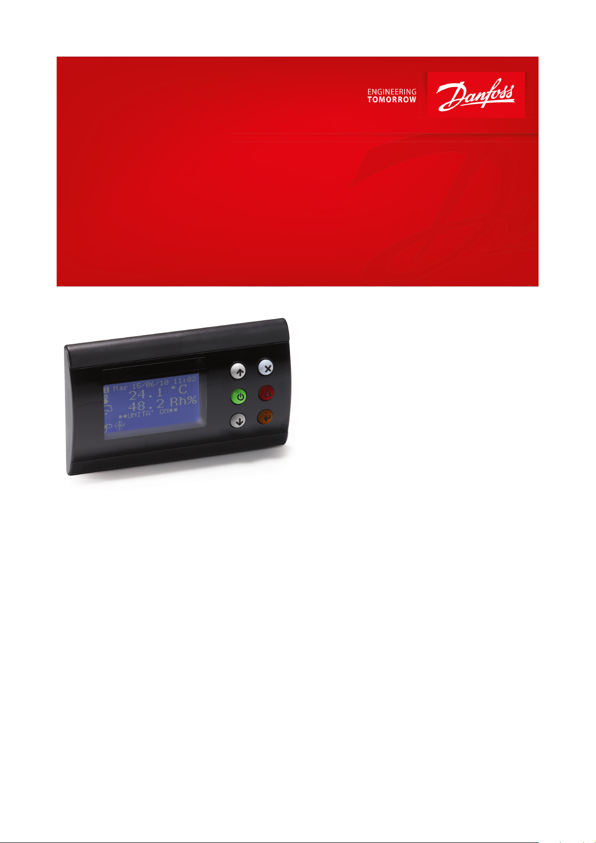
Control panel
Type MMIGRS2CC
Electronic controller suitable for all HVAC/R software application needs.
MMIGRS2CC close control is MCX’s family
remote interface. It’s tted with a graphic
display that allows a complete customization of
the user interface. The connection with every
unit of the MCX range is made through the
CANbus network. All the information about the
user interface is loaded inside the MCX
controller; that’s why there is no need of
programming the MMIGRS2CC interface.
MMIGRS2CC is powered externally or from the
controller which it is connected to and
automatically shows its user interface.
Features:
• Full graphic LCD display, 128 x 64 dots
resolution
• Easy connection to MCX CANbus network
through telephone plug and CAN connector
• No need to be programmed: information
about user interface is loaded from the MCX
controller
• Powered by the MCX which it is connected to
• Dimensions 88 x 150 mm
• Panel and wall mounting
• IP64 protection rating on panel version
• 2 dedicated keys for easy access to alarm and
ON/OFF functions
• 3 coloured back lighted keys: red, orange and
green
AI184486420989en-000501
Page 2
Features
Description
Power supply
From the MCX through the RJ12 telephone connector
12 – 30 V DC SELV (separate power supply is recommended)
24 V AC +10% / -15% SELV (separate power supply is recommended)
Maximum power consumption: 1.5 W
Plastic housing
Self extinguishing V0 according to IEC 60695-11-10 and glowing / hot wire test at 960 °C according to IEC 60695-2-12
Ball test
125 °C according to IEC 60730-1
Leakage current: ≥ 250 V according to IEC 60112
Operating conditions
CE: -20T60 / UL: -20T60, 90% RH non-condensing
Storage conditions
-30T80, 90% RH non-condensing
Integration
In Class I and / or II appliances
Index of protection
IP64 ~ NEMA3R (panel version)
IP40 (wall version)
Period of electric stress across insulating parts
Long
Resistance to heat and re
Category D
Immunity against voltage surges
Category II
Software class and structure
Class A
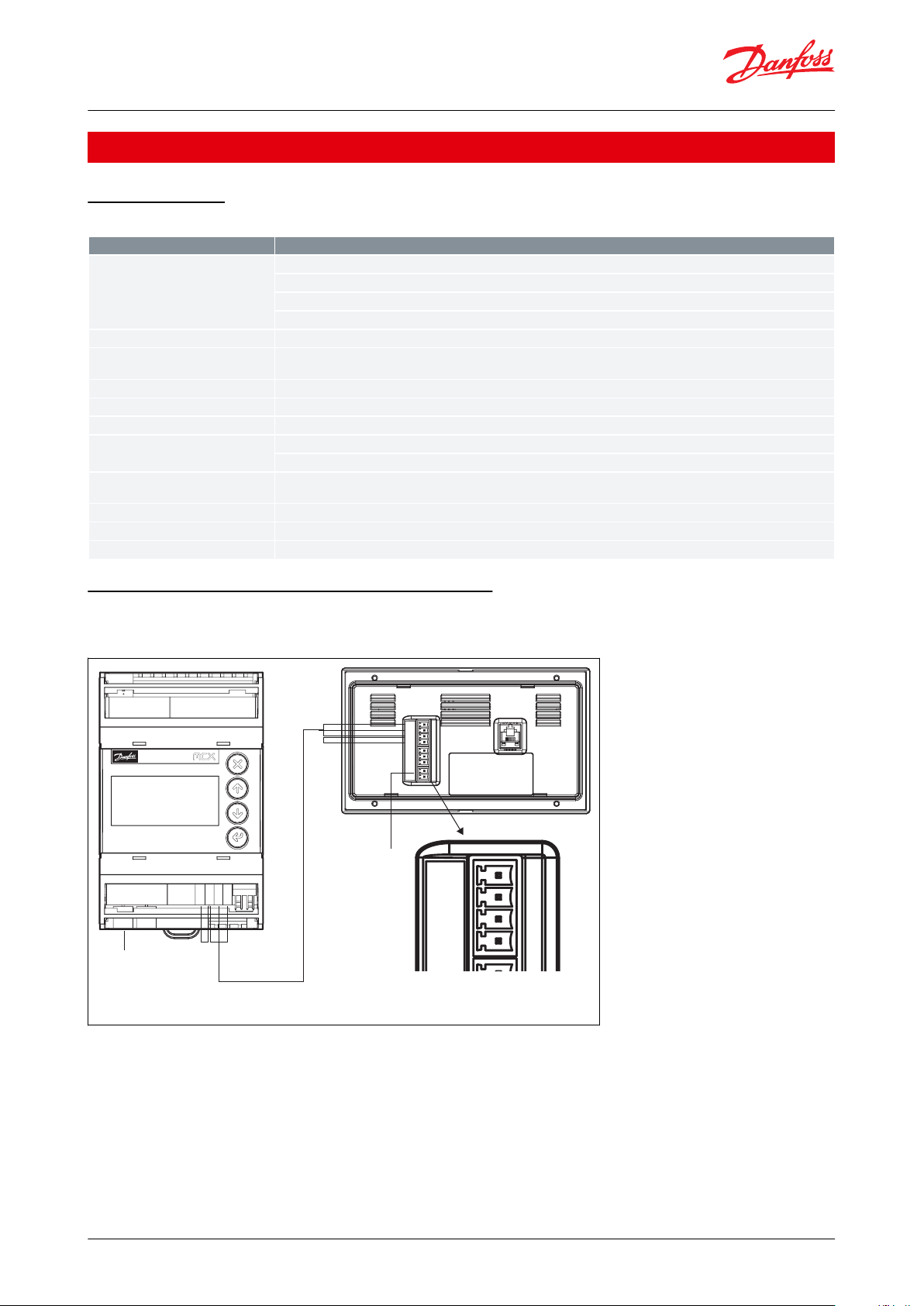
MCX06D
MMIGRS2CC
POWER
SUPPLY
24 V AC
CAN
R H L
POWER
SUPPLY
24 V AC
12 V DC
G
N
D
L H R
G
N
D
*
L H R
G
N
D
Danfoss
80G8083.01
Control panel, type MMIGRS2CC
Product specication
General features
Table 1: General features
Connection diagram – MCX or MCX06 connection
CANH-R connection should be done only on the rst and last element of the network
Figure 1: MCX06D - MMIGRS2CC
© Danfoss | Climate Solutions | 2021.03 AI184486420989en-000501 | 2
Page 3

MCX MMIGRS2CC
ACCCBI080G0075 or 080G0076
POWER SUPPLY
24 V AC
230 V AC
CAN RJ
R120
CAN H
CAN L
C GND
CAN RJ
Connectors
Type
Dimensions
Power supply connector
24 V AC - 2 way screw plug-in connector type
• pitch 3.5 mm
• section cable 0.08 – 1.5 mm²
CAN connector
4 way screw plug-in connector type
• pitch 3.5 mm
• section cable 0.08 – 1.5 mm²
CAN-RJ connector
6/6 way telephone RJ12 plug type
Control panel, type MMIGRS2CC
Figure 2: MCX - MMIGRS2CC
NOTE:
*When MMI is not connected to MCX via telephone cable, the autodetection feature of the MCX CAN address will
not work.
Therefore check the following MMIGRS2CC setting:
1.
Enter BIOS menu pressing and holding X + Enter keys for 5 seconds.
2.
Select “MCXselection” → ”Manual Mode” and set the CAN address of the MCX you wish to connect to.
Connection
Table 2: Connection
© Danfoss | Climate Solutions | 2021.03 AI184486420989en-000501 | 3
Page 4

88
68
150 16 19
137
ø 2.8 ± 0.1 (x4)
69
76 ± 0.5
138
110 ± 0.5
Danfoss
80G8082.01
88
150 31.7
Danfoss
80G8082.01
Type
Features
Description
LCD display
Display
Graphical LCD blue transmissive
Backlight
White LED backlight adjustable via software
Contrast
Adjustable via software
Format
128 x 64 dots
Active visible area
66.5 x 33.2 mm
Keyboard
Number of keys
6, of which 3 with respectively green, red, orange LEDs that can be individually managed via software
Keys function
Set by the application software
Mounting
Panel mounting
See the drilling template in
gure, using the screws supplied in the
packaging
Wall mounting
Standard 3 modules box
Control panel, type MMIGRS2CC
Dimensions
Figure 3: Panel mounting
Figure 4: Wall mounting
User interface
Table 3: User interface
© Danfoss | Climate Solutions | 2021.03 AI184486420989en-000501 | 4
Page 5

Description
Code No.
MMIGRS2, Close Control, Wall, S
080G0299
MMIGRS2, Close Control, Panel, I (27 pieces)
080G0298
Description
Code No.
ACCCBI, Telephone Cable User Interface Connector, 1.5 m Cable
080G0075
ACCCBI, Telephone Cable User Interface Connector, 3 m Cable
080G0076
File name
Document type
Document topic
Approval authority
080R2089.02
EU Declaration of conformity
EMC directive 2014/30/EU:
EN61000-6-3: 2007 +A1: 2011
EN61000-6-2: 2005
RoHS directive 2011/65/EU and 2015/863/EU:
EN 50581: 2012
Danfoss
UL E31024
Electrical - Safety
Certicate
–
UL
Control panel, type MMIGRS2CC
Ordering
Product part numbers
Table 4: Product part numbers
NOTE:
Both single pack codes (S) and industrial pack codes (I) include standard kit connector.
Accessories part numbers
Table 5: Accessories part numbers
Certicates, declarations, and approvals
The list contains all certicates, declarations, and approvals for this product type. Individual code number may have
some or all of these approvals, and certain local approvals may not appear on the list.
Some approvals may change over time. You can check the most current status at danfoss.com or contact your local
Danfoss representative if you have any questions.
Table 6: Certicates, declarations, and approvals
© Danfoss | Climate Solutions | 2021.03 AI184486420989en-000501 | 5
Page 6

Online support
Danfoss oers a wide range of support along with our products, including digital product information, software,
mobile apps, and expert guidance. See the possibilities below.
The Danfoss Product Store
The Danfoss Product Store is your one-stop shop for everything product related—no matter where
you are in the world or what area of the cooling industry you work in. Get quick access to essential
information like product specs, code numbers, technical documentation, certications, accessories,
and more.
Start browsing at store.danfoss.com.
Find technical documentation
Find the technical documentation you need to get your project up and running. Get direct access to
our ocial collection of data sheets, certicates and declarations, manuals and guides, 3D models
and drawings, case stories, brochures, and much more.
Start searching now at www.danfoss.com/en/service-and-support/documentation.
Danfoss Learning
Danfoss Learning is a free online learning platform. It features courses and materials specically
designed to help engineers, installers, service technicians, and wholesalers better understand the
products, applications, industry topics, and trends that will help you do your job better.
Create your Danfoss Learning account for free at www.danfoss.com/en/service-and-support/learning.
Get local information and support
Local Danfoss websites are the main sources for help and information about our company and
products. Find product availability, get the latest regional news, or connect with a nearby expert—all
in your own language.
Find your local Danfoss website here: www.danfoss.com/en/choose-region.
Danfoss can accept no responsibility for possible errors in catalogues, brochures and other printed material. Danfoss reserves the right to alter its
products without notice. This also applies to products already on order provided that such alterations can be made without subsequential
changes being necessary in specications already agreed. All trademarks in this material are property of the respective companies. Danfoss and
the Danfoss logotype are trademarks of Danfoss A/S. All rights reserved.
© Danfoss | Climate Solutions | 2021.03 AI184486420989en-000501 | 6
 Loading...