

Page 1
Data sheet
CI-tronic™ Soft starters for Danfoss commercial
compressor applications
Type MCI 15C, MCI 25C, MCI 50CM-3 I-O
The MCI compressor soft starters are designed for
soft starting of 3 phase compressors.
During start the MCI will gradually increase the
voltage to the motor until it reaches full line
voltage.
The soft start ramp-up time and initial start
torque is preset to ensure a fast start and allow
easy and quick installation.
MCI compressor soft starters are ideal for use on
Danfoss Performer scroll and Maneurop
Reciprocating compressors. The starting current
can be reduced by up to 40% of the direct on line
value.
Features • Universal control voltage: 24 – 480 V AC/DC
• Automatic detection of missing phases
• LED Status indication.
• Automatic adaptation to 50/60 Hz
• Easy and quick installation
• Up to 12 start/stop operations per hour
• Built in varistor protection
• IP20 Protection
• Compact modular design
• DIN rail mountable
• Ramp-time max. 0.5 s (factory set-up)
• EN 60947-4-2
© Danfoss | DCS (az) | 2018.04
IC.PD.C50.B3.02 | 1
Page 2
Data sheet | CI-tronic™ Soft starters for Danfoss commercial compressor applications, Type MCI 15C, MCI 25C, MCI 50CM-3 I-O
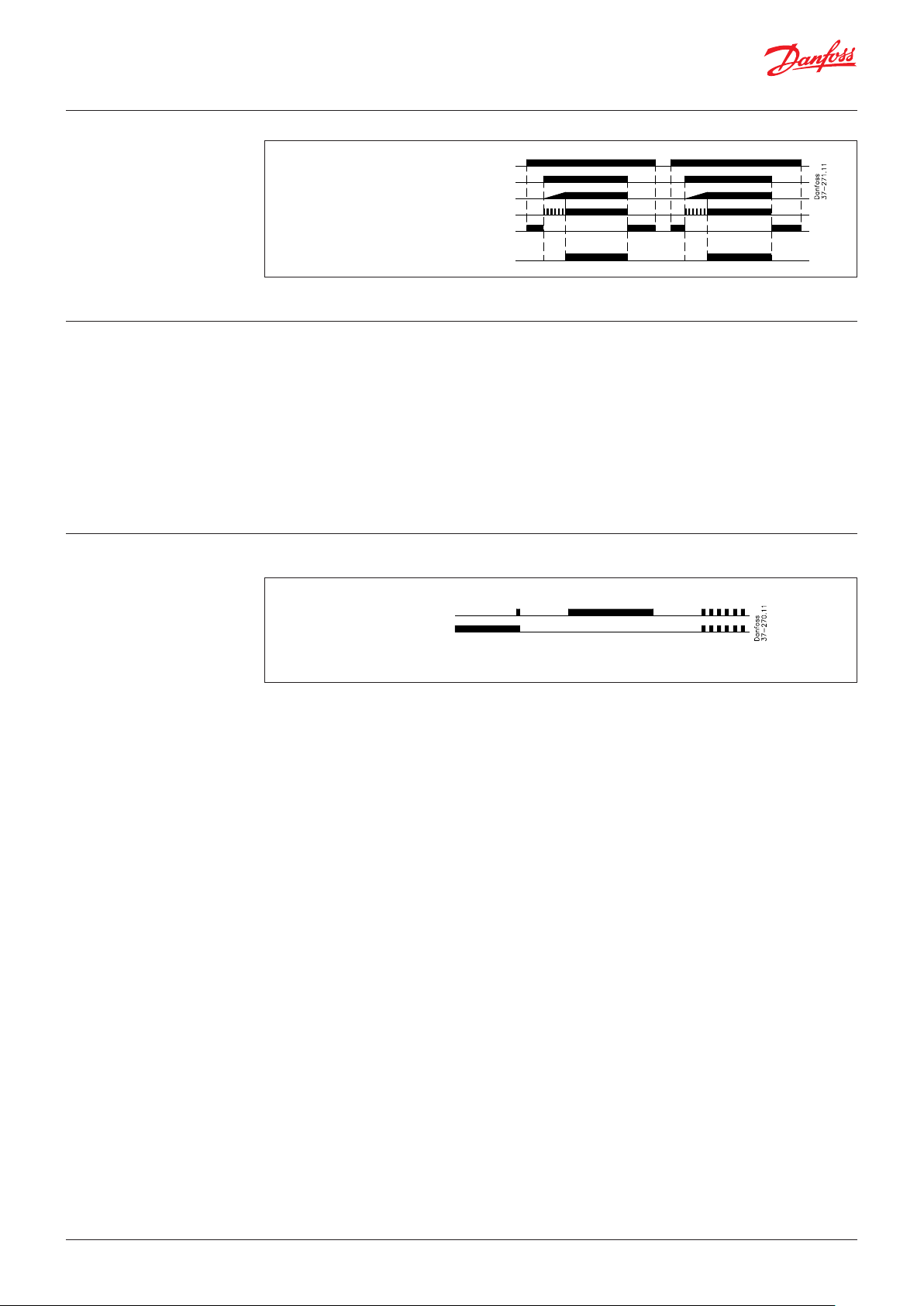
Functional diagram
Mains voltage, L1, L2, L3
Control voltage (A1, A2)
Motor voltage ( T1, T2, T3)
LED 1
LED 2
23-24 bypass (MCI 25C/MCI 50CM-3 I-O)
SCR contact:
Functional description
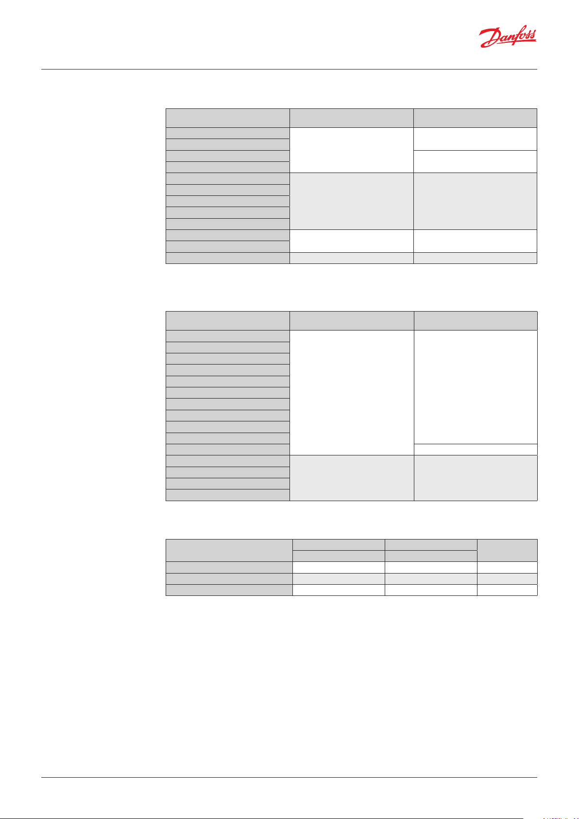
LED status indication
Start
During ramp-up the controller will gradually
increase the voltage to the motor from the preset
initial torque value until it reaches full line
voltage. The actual ramp time is digitally
calculated and will not be influenced by net
frequency or load variations.
LED 1
LED 2
Stand Ramp Full Line or
by up on load error
Bypass mode (contact 23-24, only MCI 25C/
MCI 50CM-3 I-O)
The auxiliary contacts are made possible by
means of SCR technology and will only switch
correctly on a.c. current. The contact is intended
for operating an external bypass contactor. The
contact will close when the controller is in steady
state operation, see application example page 7.
© Danfoss | DCS (az) | 2018.04
IC.PD.C50.B3.02 | 2
Page 3
Data sheet | CI-tronic™ Soft starters for Danfoss commercial compressor applications, Type MCI 15C, MCI 25C, MCI 50CM-3 I-O
Soft starter selection guide
Performer® scroll compressors
Motor voltage code 4, 400 V - 3 phase - 50 Hz / 460 V - 3 phase - 60 Hz
Compressor model
SM/SZ 084
SM/SZ 090
SM/SZ 100
SM/SZ 110
SM/SZ 115-125
SM/SZ 120
SM/SZ 160
SM/SZ 148-161
SM/SZ 175-185
SY/SZ 240
SY/SZ 300
SZ 380 MCI 50CM-3 I-O 1) MCI 50CM-3 I-O 1)
) The controller must be by-passed in steady state mode. See application example page 7
Soft starter type
Ambient temp. max. 40 °C
MCI 15C
MCI 25C MCI 25C 1)
MCI 50CM-3 I-O 1) MCI 50CM-3 I-O 1)
Soft starter type
Ambient temp. max. 55 °C
MCI 15C
MCI 25C
Maneurop® compressors
Motor voltage code 4, 400 V - 3 phase - 50 Hz / 460 V - 3 phase - 60 Hz
Compressor model
MT/MTZ 18-22
MT/MTZ 28
MT/MTZ 32
MT/MTZ 36
MT/MTZ 40
MT/MTZ 44-50
MT/MTZ 45-51
MT/MTZ 56
MT/MTZ 57-65
MT/MTZ 64
MT/MTZ 72-73-80-81 MCI 25C
MT/MTZ 100
MT/MTZ 125
MT/MTZ 144
MT/MTZ 160
) The controller must be by-passed in steady state mode. See application example page 7
Soft starter type
Ambient temp. max. 40 °C
MCI 15C
MCI 25C MCI 25C 1)
Soft starter type
Ambient temp. max. 55 °C
MCI 15C
© Danfoss | DCS (az) | 2018.04
MCI C Soft Starter selection
Type
MCI 15C 380 – 480 45 037N0076
MCI 25C 380 – 480 90 037N0077
MCI 50CM-3 I-O 380 – 480 180 037N0401
Operational voltage Module dimensions
[V AC] [mm]
Code no.
IC.PD.C50.B3.02 | 3
Page 4

Data sheet | CI-tronic™ Soft starters for Danfoss commercial compressor applications, Type MCI 15C, MCI 25C, MCI 50CM-3 I-O
Technical data
Output specifications MCI 15C MCI 25C MCI 50CM-3 I-O
Operational voltage V AC 380 – 480 380 – 480 380 – 480
Operational current (AC-3, AC-53a, AC-53b) max. 15 A 25 A / 30 A 35 A / 50 A
Ramp up time (preset) max. 0.4 s 0.4 s 0.5 s
Leakage current max. 5 mA 5 mA 5 mA
Operational current min. 50 mA 50 mA 50 mA
Overload relay trip class Class 10 Class 10 Class 10
Semiconductor protection fusing:
Type 1 1) co-ordination 50 A gL/gG 100 A gL/gG 125 A gL/gG
Type 2 2) co-ordination I2t(t=10 ms) 1800 A2 S 6300 A2 S 25300 A2 S
Rating index:
AC-53a Asynchronous motors 3)
15A: AC-53a:
8-3: 100-3000
AC-53b Asynchronous motors with bypass -
1)
Type 1 coordination require that, under short-circuit conditions, the device shall cause no danger to persons or installation and
may not be suitable for further use without repair and replacement of parts
2)
Type 2 coordination require that, under short-circuit conditions, the device shall cause no danger to persons or installation and
shall be suitable for further use
3)
15A: AC-53a: 8-3:100-3000 means max. load 8x15A for 3 seconds. 100% ON-load factor or 3000 operations per hour
25A: AC-53a:
8-3: 100-3000
30A: AC-53b:
6-3: 30
35A: AC-53a:
6-6: 100-120
50A: AC-53b:
6-3: 30
Control circuit specifications
Control voltage range 24 – 480 V AC/DC
Pick-up voltage max. 20.4 V AC/DC
Drop-out voltage min. 5 V AC/DC
Control current for no operation max. 1 mA
Control current / power max. 15 mA / 2 VA
Response time max. 70 ms
SCR by-pass contact, optional
Voltage / current (AC-14, AC-15) max. 24 – 240 V / 0.5A 24 – 240 V / 0.5A 24 – 240 V / 1.0A
Fuse max. 10 A gL/gG, I2t max. 72 A2s
EMC immunity Meets requirements of EN 50082-1 and EN 500082-2
Insulation
Rated insulation voltage U
i
Rated impulse withstand voltage U
4 kV
imp
660 V AC
Installation category III
Thermal specification
Cooling method Natural convection
Mounting Vertical +/- 30°
Storage temperature range -20 °C – 80 °C
Enclosure degree / pollution degree IP20 / 3 IP20 / 3 IP10 / 3
Power dissipation, continuous duty max. 2 W/A 2 W/A 3 W/A
Power dissipation, intermittent duty max. 2 W/A × duty cycle 2 W/A × duty cycle 3 W/A × duty cycle
Materials
Housing self extinguishing PPO UL94V1
Heatsink aluminium Black anodized
Base Electroplated steel
© Danfoss | DCS (az) | 2018.04
IC.PD.C50.B3.02 | 4
Page 5

Data sheet | CI-tronic™ Soft starters for Danfoss commercial compressor applications, Type MCI 15C, MCI 25C, MCI 50CM-3 I-O
Dimensions
MCI 15C MCI 25C
MCI 50CM-3 I-O
Mounting instructions
The controller is designed for vertical mounting.
If the controller is mounted horizontally the load
current must be reduced by 50%.
The controller needs no side clearance.
Clearance between two vertical mounted
controller must be minimum 80 mm (3.15”).
Clearance between controller and top and
bottom walls must be minimum 30 mm (1.2”).
© Danfoss | DCS (az) | 2018.04
IC.PD.C50.B3.02 | 5
Page 6

Data sheet | CI-tronic™ Soft starters for Danfoss commercial compressor applications, Type MCI 15C, MCI 25C, MCI 50CM-3 I-O
Overload and short circuit
protection
Performer®
scroll compressors
Maneurop®
reciprocating compressors
Overload and short circuit protection is easily
achieved by installing a circuit breaker on the
line side of the motor controller. Select the circuit
breaker from the table below.
Motor voltage code 4 / 400 V - 3ph - 50 Hz / 460 V - 3ph - 60 Hz
Compressor type
SM/SZ 084 17 CTI 25M 047B3150
SM/SZ 090 17 CTI 25M 047B3150
SM/SZ 100 19 CTI 25M 047B3151
SM/SZ 110 20 CTI 25M 047B3151
SM/SZ 115 25 CTI 25M 047B3152
SM/SZ 120 29 CTI 25M 047B3152
SM/SZ 125 25 CTI 25M 047B3152
SM/SZ 148 32 CTI 45MB 047B3164
SM/SZ 161 32 CTI 45MB 047B3164
SM/SZ 160 29 CTI 25M 047B3152
SM/SZ 175 35 CTI 45MB 047B3164
SM/SZ 185 35 CTI 45MB 047B3164
SY/SZ 240 50 CTI 45MB 047B3165
Compressor type
MT/MTZ 18 5 CTI 25M 047B3147
MT/MTZ 22 6 CTI 25M 047B3148
MT/MTZ 28 7.5 CTI 25M 047B3148
MT/MTZ 32 8 CTI 25M 047B3149
MT/MTZ 36 9 CTI 25M 047B3149
MT/MTZ 40 10 CTI 25M 047B3149
MT/MTZ 44 9.5 CTI 25M 047B3149
MT/MTZ 45 9.5 CTI 25M 047B3149
MT/MTZ 50 12 CTI 25M 047B3150
MT/MTZ 51 11.5 CTI 25M 047B3149
MT/MTZ 56 12 CTI 25M 047B3150
MT/MTZ 57 12 CTI 25M 047B3150
MT/MTZ 64 15 CTI 25M 047B3150
MT/MTZ 65 14 CTI 25M 047B3150
MT/MTZ 72 15.5 CTI 25M 047B3150
MT/MTZ 73 17 CTI 25M 047B3150
MT/MTZ 80 18 CTI 25M 047B3151
MT/MTZ 81 19 CTI 25M 047B3151
MT/MTZ 100 22 CTI 25M 047B3151
MT/MTZ 125 27 CTI 25M 047B3152
MT/MTZ 144 30 CTI 45MB 047B3164
MT/MTZ 160 36 CTI 45MB 047B3164
Compressor max. current
[A]
Motor voltage code 4 / 400 V - 3ph - 50 Hz / 460 V - 3ph - 60 Hz
Compressor max. current
[A]
Be aware of the maximum prospective short
circuit current breaking capacity. For further
information please refer to the data sheet on the
circuit breaker.
Danfoss CTI
Type Code no.
Danfoss CTI
Type Code no.
Overheat protection If required, the controller can be protected
against overheating by inserting a thermostat in
the slot on the right-hand side of the controller.
Order: UP 62 thermostat, code no. 037N0050
For wiring connections see application examples
below.
© Danfoss | DCS (az) | 2018.04
IC.PD.C50.B3.02 | 6
Page 7

Danf
already on order pro
All trademarks in this material are property of the respec
Application examples
Overheat protection
The thermostat is connected in series with the
control circuit of the main contactor.
When the temp. of the heat sink exceeds 90 °C
the main contactor will be switched OFF.
This circuit requires manual reset to restart the
motor.
Line controlled soft start
When the contactor K1 is switched to the ONstate, the soft starter will start the motor,
according to the settings of the ramp-up time
and initial torque adjustments. When the
contactor K1 is switched to the OFF-state the motor will be switched off instantaneously.
In this application the contactor will have no load
during opertion.
The contactor will carry and break the nominal
motor current.
Danfoss
37N51
MCI 25 with bypass contactor
By means of the built-in auxiliary contact the
bypass function is easily achieved, see wiring
diagram from the side.
No heat is generated from the MCI.
As the contactor always switches in no-load
condition it can be selected on the basis of the
thermal current (AC-1).
(13-14 contact not applicable with MCI 25C and
MCI 50CM-3 I-O).
Input controlled soft start
When the control voltage is applied to A1 - A2,
the MCI soft starter will start the motor, according
to the settings of the Ramp-up time and Initial
torque adjustments. When the control voltage is
switched OFF, the motor will switch off
instantaneously.
oss can accept no responsibility for possible errors in catalogues, brochures and other printed material. Danfoss reserves the right to alter its products without notice. This also applies to products
vided that such alterations can be made without subsequential changes being necessary eady agreed.
© Danfoss | DCS (az) | 2018.04
tive companies. Danfoss and the Danfoss logotype are trademarks of Danfoss A/S. All rights reserved.
IC.PD.C50.B3.02 | 7
 Loading...