

Page 1
Data Sheet
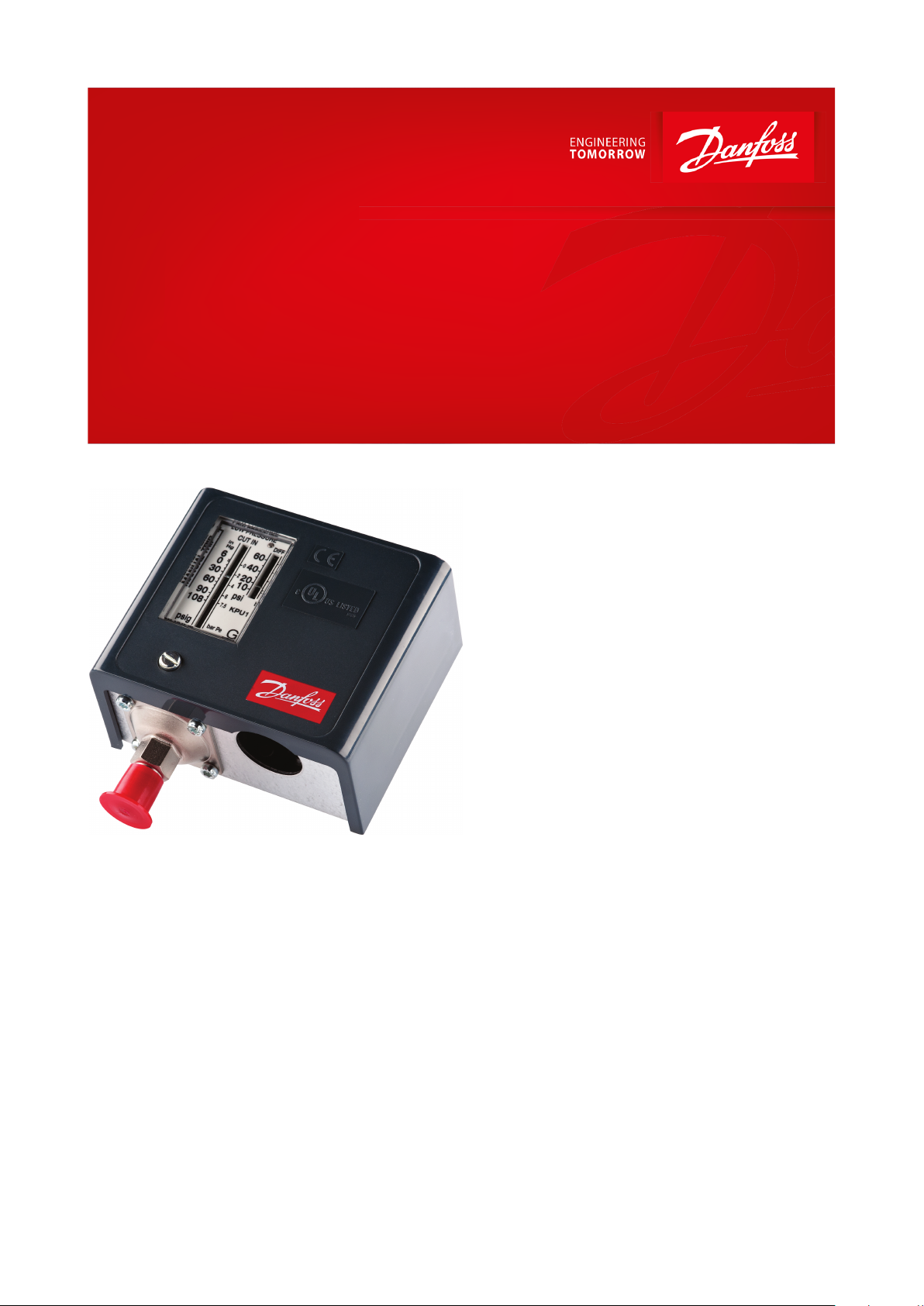
Pressure switch
Type KPU
The KPU pressure switches are designed for use
in refrigeration and air-conditioning systems to
protect the systems from excessively low
suction pressure or too high discharge
pressure. They can also be applied to start and
stop compressors and the fans of air-cooled
condensers.
The KPU pressure switches, in single and dual
versions cover a comprehensive range of
applications, and are designed for use with
HCFC and non-ammable HFC refrigerants.
Features:
• Snap action electrical contacts minimize
chatter, bounce, and wear, and ensure
longterm electrical and mechanical reliability
• The fail-safe dual bellows used in KPU 6 and
KPU 16 prevent refrigerant loss and enable
premature cut-out when a fault occurs
• SPDT or SPST switch a in single control
models. SPST or SPDT with high-low pressure
signal in dual control models
• Manual trip function (electrical contact
function can be tested without the use
of tools)
• Easily replaces Johnson Controls and Ranco
products
• Wide pressure range:from low pressure KPU 2
with narrow dierential to KPU 6 and KPU 16
for high pressure refrigerants (R410A, R744)
• Automatic, manual or convertible reset
versions available
• Vibration and shock resistant
AI216886432210en-000901
Page 2

Unit type
Material
KPU 1, KPU 2, KPU 5, KPU 15
Tin bronze, no. CW452K, EN 1652 Nickel plated free cutting steel, no. 1.0737/ 1.0718 to EN 10277
KPU 6, KPU 16
Stainless steel bellows
KPU with capillary tube
Copper SF-CU no. 2.0090 to DIN 1787
Ambient temperature
-40 – 122 °F (175 °F for max 2 hours)
Maximum working pressure
Low pressure (LP)
KPU 1, KPU 2 and LP side of KPU 15, KPU 16: 250 psig
High pressure (HP)
KPU 5 and KPU 15 on HP side: 510 psig
KPU 6 and KPU 16 on HP side: 675 psig
KPU 6 and KPU 16 on HP side: 610 psig for products used according to 2014/68/EU PED directive
Maximum testing pressure
Low pressure (LP)
KPU 1, KPU 2 and LP side of KPU15, KPU16: 290 psig
High pressure (HP)
KPU 5 and KPU 15 on HP side: 530 psig
KPU 6 and 16 on HP side: 725 psig
Cable entry
7
⁄8 in cable entry for 1⁄2 in male pipe thread connection (conduit boss)
Contact load
Alternating current
FLA = 24 A @ 120 V AC
24 A @ 240 V AC
LRA = 144 A @ 120 V AC
144 A @ 240 V AC
LRA is rated for make only
Direct current
240 V DC: 12W pilot duty
Wire dimension
10 AWG maximum
Enclosure
~NEMA 1
Pressure switch, KPU
Product specication
Materials in contact with medium
Table 1: Materials
Technical data
Table 2: Technical data
Terminology
Set point
A predetermined value to which a switch is adjusted and at which it performs its intended function.
Reset
1. Manual reset
A unit with manual reset can only be restored to operational mode by activating the external reset button.
2. Automatic reset
A unit with automatic reset is restored to operational mode automatically.
3.Convertible reset
A unit with convertible reset can be adjusted for either automatic or manual reset.
Maximum working pressure
The maximum permissible pressure for safe functioning of a refrigeration system or any of its parts.
Maximum test pressure
The maximum pressure applied in strength or leakage tests on refrigeration systems or components thereof.
Dierential
Dierential is the number of psi (or bar) by which cut-in and cut-out set points are separated.
Snap function
A specic contact force is maintained until snap is initiated. The time over which contact force reaches zero is a few
milliseconds; therefore, contact bounce cannot occur as a result, for example, of slight vibrations before cut-out. The
snap-action contact system will continue to function even when micro-welds are created between the contacts
during cut-in. The force created to separate the contacts is strong, and instantly shears o all contact surface welds
that have been created as the result of cut-in action. These design features ensure that the cut-out point of the KPU
switch remains very accurate and completely independent of the magnitude of the current load.
© Danfoss | Climate Solutions | 2021.02 AI216886432210en-000901 | 2
Page 3

Pressure switch, KPU
Fail-safe switch
A switch is fail-safe if it has the capability to remain in a safe condition or transition to a safe condition when a fault
occurs.
FLA – Motor Full Load Amperes
The current rating, in amperes, of the motor when a full load is applied to it for work being done.
LRA – Locked Rotor Amperes
The current drawn, in amperes, by an electric motor with the shaft or rotor stopped and locked in position.
Setting
Cut-in and cut-out pressures for both LP and HP sides of the system should always be checked with an
accurate pressure gauge.
Low Pressure setting for switches with automatic reset
1.
Set the LP cut-in pressure on the “CUT-IN” scale (range scale). One rotation of the low pressure spindle ~ 5.2 psi
for KPU 2 and ~6.8 psi for KPU 1.
2.
Set the LP dierential on the “DIFF” scale. One rotation of the dierential spindle ~ 3.2 psi for KPU 2 and 2.9 psi
for KPU 1.
NOTE:
The LP cut-out pressure is LP cut-in pressure minus dierential value. The LP cut-out pressure must be above
absolute vacuum (Pe = 29.5 in Hg).
High Pressure setting for switches with automatic reset
1.
Set the HP cut-out pressure on the “CUT-OUT” scale. One rotation of the HP spindle ~ 22 psi for KPU 5 and ~ 28
psi for KPU 6.
2.
Set the HP dierential on the “DIFF” scale. One rotation of the dierential spindle ~ 5.3 psi for KPU 5 and ~ 8.6 psi
for KPU 6.
NOTE:
The HP restart pressure is equal to HP cut-out pressure minus dierential.
Pressure switches with manual reset Set the cut-out pressure on the “CUT-OUT” scale (range scale). Low Pressure
switches can be manually reset when the pressure is above the cut-out pressure plus the dierential. High Pressure
switches can be manually reset when the pressure is below cut-out minus dierential.
© Danfoss | Climate Solutions | 2021.02 AI216886432210en-000901 | 3
Page 4

1
2
345678910111213141516171819
Pressure switch, type KPU
KPU single (KPU 1, KPU 2, KPU 5, KPU 6) without front cover
KPU dual (KPU 15, KPU 16) without front cover
Low pressure (LP) setting
spindle
High pressure (HP) setting
spindle
Dierential
Low pressure main spring
High pressure main spring
Dierential spring
Ground terminal
Cable entry
Bellows
LP connection
HP connection
Control terminals
Reset button
Arm
Switch
Tumbler
Locking plate
Contact housing
Damping device
Pressure switch, KPU
Design and Function
Table 3: KPU types
Switch function
The switch in KPU control has a snap-action function and the bellows moves only when cut-in or cut-out set point is
reached.
This design has following advantages:
• high contact load
• ultra-short bounce time
• long mechanical and electrical lifetime
• high resistance to pulsation and vibrations
© Danfoss | Climate Solutions | 2021.02 AI216886432210en-000901 | 4
Page 5

123
Pressure connection
Regulating bellows
Outer bellows
KPU single
KPU dual
0.47 in.
3.01 in.
1.17 in.
3.52 in. 1.83 in.
1.83 in.5.22 in.
0.47 in.
1.17 in.
3.01 in.
Approx. net weight: 0.765 lbs
Approx. net weight: 1.19 lbs
KPU single
KPU dual
6.75 in.
3.01 in.
3.52 in.
1.83 in.
3.01 in.
6.75 in.
1.83 in.5.22 in.
Approx. net weight: 0.91 lbs
Approx. net weight: 1.5 lbs
Pressure switch, KPU
Figure 1: Fail-safe bellows concept in KPU 6 and high pressure side of KPU 16
KPU 6 and high pressure side of KPU 16 have double bellows: an outer bellow and a regulating bellow. When system
pressure exceeds the set value, the KPU will automatically stop the system. The double bellows system prevents the
loss of charge in the event of bellows rupture. Rupture in the outer bellows causes the control cut-out pressure to
fall about 40 psi under the set value, thus providing fail-safe function.
Reset
Version with automatic reset cut-in again automatically when the pressure falls or rises to the set point minus
dierential. Version with manual reset have to be cut in manually with external reset button when the pressure in
KPU 1 rises min. 10 psi above the set point value, and in KPU 6 falls min. 60 psi under the set point value. All KPU
pressure switches operate independently of changes in ambient temperature around the switch. Therefore the
setting for cut-out pressure and dierential stay constant unless the permissible ambient temperature is exceeded.
Dimensions and weight
Table 4: KPU with are connection
Table 5: KPU with capillary tube
All switches are supplied with universal mounting bracket and mounting screws as standard accessory.
Approximate weight of the bracket and mounting screws: 0.615 lbs
© Danfoss | Climate Solutions | 2021.02 AI216886432210en-000901 | 5
Page 6

Pressure
Control type
Low pressure (LP)
High pressure (HP)
Reset
Contact type
Code no.
Range
[inHg][psig]
Dierential
[psi]
Range
[psig]
Dierential
[psi]
Low
pressure
(LP)
High
pressure
(HP)
Connection
¼ in male
are
36 in cap.
tube w. ¼ in
are nut
Low
KPU 1
6 – 108
10 – 60––
Auto–A
060-5231
060-5233
Low
KPU 1
6 – 108
10 – 60––
Auto–B
060-5236–Low
KPU 1B
28 – 10010––Man. (Min.)–A
060-5232
060-5234
Low
KPU 2
6 – 73
6 – 30––
Auto–B
060-5237
060-5235
Low
KPU 2
6 – 73
6 – 30––
Auto–A
060-5239
060-5240
Fan cycling
KPU 5––
100 – 465
25 – 85–Auto
B
060-5241
060-5242
Dual
KPU 15
6 – 108
10 – 60
100 – 465
60
Auto
Auto
C
060-5247
060-5248
Dual
KPU 15B
6 – 108
10 – 60
100 – 465
60
Auto
Man. (Max.)
C
060-5249
060-5250
Pressure
Control type
Low pressure (LP)
High pressure (HP)
Reset
Contact type
Code no.
Range
[inHg] [psig]
Dierential
[psi]
Range
[psig]
Dierential
[psi]
Low
pressure
(LP)
High
pressure
(HP)
Connection
¼ in male
are
36 in cap.
tube w. ¼ in
are nut
High
KPU 6W––
100 – 600
58 – 145–Auto
A
060-5243
060-5245
High
KPU 6B––
100 – 60060–
Man. (Max.)
A
060-5244
060-5246
Dual
KPU 16W
6 – 108
10 – 60
100 – 600
60
Auto
Auto
D
060-5251
060-5252
Dual
KPU 16B
6 – 108
10 – 60
100 – 600
60
Min. Conv.
Max. Conv.
D
060-5253
060-5254
Switch type
Switch action
Application
FW
SPDT
1. Terminals 1-4 close high and open low. Terminals
1-2 can be used as low pressure alarm.
1. Low pressure cut-out.
2. Terminals 1-2 open high and close low Terminals
1-4 can be used as high pressure alarm.
2. High pressure cut-out.
SPST (NO)
Terminals 1-4 close high and open low
1. Low pressure cut-out.
2. Condenser fan cycling control.
FW
SPST (NO + NC)
Dual Pressure switch employs an SPST switch that is
open when either high or low pressure beyond the
control setting is sensed on the two bellows sensing
elements of the switch.
Dual Pressure switch Protects the system against too
low suction pressure and against too high discharge
pressure.
FW
SPDT + SPST (NO)
Contact opens on pressure drop below LP set point
(turns on the LP signal light) and on pressure rise
above HP set point (turns on HP signal light). Contact
action is controlled by two bellows sensing elements.
Note: max. contact D rating is 50 VA
Dual Pressure switch. Protects the system against too
low suction pressure (LP cut-out signal on terminal B)
and against too high discharge pressure (HP signal on
terminal D).
Pressure switch, KPU
Ordering
For complete list of approved refrigerants, visit www.products.danfoss.com and search for individual code numbers,
where refrigerants are listed as part of technical data.
Table 6: For R22, R134a, R404A, R407A, R407C, R407F, R422B, R422D, R438A, R448A, R449A, R450A, R452A, R507A, R513A
Table 7: Fail-safe switches for high pressure refrigerants (R410A, R744) PED 2014/68/EU approved according to EN 12263
During standstill the ambient temperature cannot be higher than 82 °F for R410A and higher than -11 °F for R744 as
the LP side bellows MWP (250 psig) will be exceeded.
Contact system and application
Table 8: Contact system and application
© Danfoss | Climate Solutions | 2021.02 AI216886432210en-000901 | 6
Page 7

Load
Signal option
Bellows movement on pressure rise
Bellows movement on pressure drop
Low pressure
Manual reset.
(1)
Automatic reset
Automatic reset
Manual reset
High pressure
Manual reset.
(1)
Manual reset
Automatic reset
Automatic reset
File name
Document type
Document topic
Approval authority
UA.1O146.D.00075-19
UA Declaration
EMCD/LVD
LLC CDC EURO TYSK
UL E31024
Certicate
Electrical - Safety
Certicate
-ULTÜV 01 202 PL-Q-11 0004
Quality - Assurance
Certicate
-
PED
Pressure switch, KPU
Pressure switch setting with convertible reset
Table 9: Pressure switch setting with convertible reset
(1)
(1)
Factory setting
Factory setting
Certicates, declarations, and approvals
The list contains all certicates, declarations, and approvals for this product type. Individual code number may have
some or all of these approvals, and certain local approvals may not appear on the list.
Some approvals may change over time. You can check the most current status at danfoss.com or contact your local
Danfoss representative if you have any questions.
Table 10: Certicates, declarations, and approvals
UL listed for USA and Canada, E31024
© Danfoss | Climate Solutions | 2021.02 AI216886432210en-000901 | 7
Page 8

Online support
Danfoss oers a wide range of support along with our products, including digital product information, software,
mobile apps, and expert guidance. See the possibilities below.
The Danfoss Product Store
The Danfoss Product Store is your one-stop shop for everything product related—no matter where
you are in the world or what area of the cooling industry you work in. Get quick access to essential
information like product specs, code numbers, technical documentation, certications, accessories,
and more.
Start browsing at store.danfoss.com.
Find technical documentation
Find the technical documentation you need to get your project up and running. Get direct access to
our ocial collection of data sheets, certicates and declarations, manuals and guides, 3D models
and drawings, case stories, brochures, and much more.
Start searching now at www.danfoss.com/en/service-and-support/documentation.
Danfoss Learning
Danfoss Learning is a free online learning platform. It features courses and materials specically
designed to help engineers, installers, service technicians, and wholesalers better understand the
products, applications, industry topics, and trends that will help you do your job better.
Create your Danfoss Learning account for free at www.danfoss.com/en/service-and-support/learning.
Get local information and support
Local Danfoss websites are the main sources for help and information about our company and
products. Find product availability, get the latest regional news, or connect with a nearby expert—all
in your own language.
Find your local Danfoss website here: www.danfoss.com/en/choose-region.
Coolselector®2 - nd the best components for you HVAC/R system
Coolselector®2 makes it easy for engineers, consultants, and designers to nd and order the best
components for refrigeration and air conditioning systems. Run calculations based on your operating
conditions and then choose the best setup for your system design.
Download Coolselector®2 for free at coolselector.danfoss.com.
Danfoss can accept no responsibility for possible errors in catalogues, brochures and other printed material. Danfoss reserves the right to alter its
products without notice. This also applies to products already on order provided that such alterations can be made without subsequential
changes being necessary in specications already agreed. All trademarks in this material are property of the respective companies. Danfoss and
the Danfoss logotype are trademarks of Danfoss A/S. All rights reserved.
© Danfoss | Climate Solutions | 2021.02 AI216886432210en-000901 | 8
 Loading...