

Page 1
Installation guide
Danfoss
60-763.14
Danfoss
60-763.14
Danfoss
60-763.14
60-763.14
Pressure switch
KPU
Application
KPU dual pressure switches are for use on commercial
refrigeration and air conditioning systems to protect
060R9768
compressor against excessively low suction pressure or
excessively high discharge pressure.
KPU dual pressure switches are compatible with refrigerants
listed below. KPU16W and KP16B are fail safe switches for high
pressure refrigerants. Standard enclosure is ~ NEMA 1.
Refrigerants:
R22, R134a, R404A, R407A, R407C, R407F, R410A*), R422B, R422D,
R438A, R448A, R449A, R450A, R452A, R507A, R513A
replace with:
For complete list of approved refrigerants, visit www.products.danfoss.
com and search for individual code numbers, where refrigerants are
listed as part of technical data. /
*) R410A only for KPU 16W and KPU 16B
KPU dual pressure switches are tted with the Single-Pole,
Single-Throw (SPST) or Single-Pole Double-Throw (SPDT)
switches, suitable for direct as well as indirect (with acontactor)
control.
Three versions of switch operation are available:
– automatic on LP and HP sides
– automatic on LP and manual reset on HP
– convertible manual or automatic on LP and HP sides.
Manual reset
The manual reset mechanism does not allow the pressure
switch to automatically reset after the switch has cut out. So the
pressure switch must be manually reset by the user to enable
restart of the equipment. Manual reset is possible to operate
only after return of pressure to cut in level. Before releasing
the reset it is recommended to investigate what caused the
shutdown.
Convertible reset
The convertible reset feature allows to change the operation
from automatic to manual by turning the selecting plate.
The selecting plate is located between two push buttons at the
top of the switch.
Please refer to instruction below demonstrating how to select
reset function.
060R9768
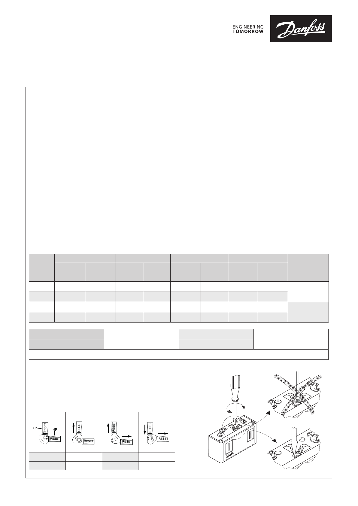
Product Specication
Code no. Low pressure (LP) High pressure (HP) Reset
Typ e
KPU 15 060 -5247 060 -5248 6 in – 108 10 – 60 100 – 465 60 Automatic Automatic
KPU 15B 060-52 49 060-525 0 6 in – 108 10 – 60 100 – 465 60 Automatic Man (Max.)
KPU 16W 060 -5251 060 -5252 6 in – 108 10 – 60 100 – 600 60 Automatic Automatic
KPU 16B 060 -5253 060-5254 6 in – 108 10 – 60 100 – 600 60 Convertible Convertible
Max. working pressure: LP side: 250 psig HP side KP U 15: 510 ps ig HP side KPU 16: 675 / 610* psig
Max. test pressure: LP side: 290 psig HP side KP U 15: 530 psig HP side KPU 16 : 725 psig
* 610psig - MWP for products used according to 2014/68/EU PED directive
1
⁄4 in
male are
36 in cap.
tube w. 1⁄4 in
are nut
Regulating
range
[inHg] [psig]
Dierential
Δp
[psi]
Regulating
range
[psig]
Dierential
Δp
[psi]
Low
pressure
High
pressure
Ambient temperature: -40 – 122 °F (175 °F for max. 2 hours)
Contact system
(NO + NC)
SPDT with
LP/HP signal
Convertible reset:
Selection of reset function on dual pressure switches with convertible
reset – turn plate to desired reset conguration.Insert a screwdriver into
the slot on the lock disc and turn it to desired reset conguration. Do not
turn the screw on the lock disc as it may damage the convertible reset
mechanism.
Danfoss
60-1408.11
SPST
LP man. LP auto. LP auto. LP man.
HP man. HP man. HP auto. HP auto.
© Danfoss | DCS (jmn) | 2017.01
Danfoss
DKRCC.PI.CD0.C6.02 | 520H11521 | 1
Page 2
Danfoss
60-1259.11
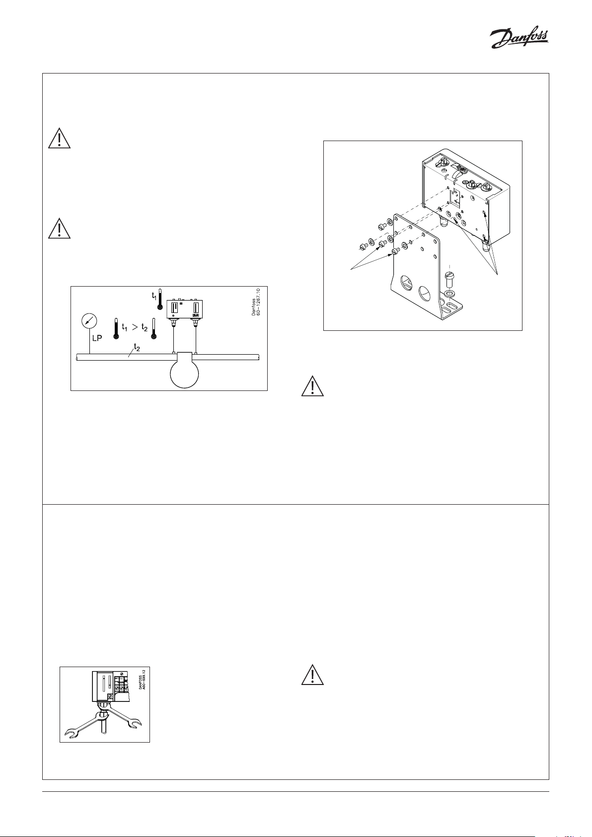
Installation
Select an accessible location, where the switch and pressure
connection line will not be subject to damage.
IMPORTANT:
Mount the pressure switch in a position that will allow
drainage of liquids away from switch bellows. Pressure
connection of the switch must always be located on the
top side of the refrigerant line. This reduces the possibility
of oil, liquids, or sediment collecting in the bellows, which
could cause theswitch malfunction.
IMPORTANT:
Ensure the ambient temperature for the dual pressure
switch on LP side is higher than the refrigeration line as
that will prevent liquid migration and accumulation in
the bellows.
For bracket mounting use only the 10-32x3/16 screws provided
with the switch. If other screws are used, function of the pressure
switch might be disturbed (they should not protrude into the
switch more than ⁄in).
Screws for
bracket mounting
Mounting holes
for at surfaces
Recommended
mounting position
Mount the KPU pressure switch on a bracket or on acompletely
at surface. Mounting to an uneven surface might cause
improper switch operation.
Recommendations for capillary tube and are connections:
1. Ensure self-draining of the capillary tube to minimize
clogging.
2. Coil excess capillary tube into smooth, circular coils (approx.
3 inch diameter). The coiled tube should be securely fastened
in order to prevent possible damage due to vibration.
3. Leave a little slack in the capillary tube as it helps to damp
mechanical vibrations.
4. Avoid sharp bends as well as re-bending of the capillary tube
on the same point as it weakens the material, increasing the
risk of crack.
5. Never allow for contact between the capillary tube and sharp
or abrasive objects as during vibrations the tube could be
damaged due to friction.
6. Purge the piping before connecting pressure switches.
7. Always use two wrenches
tightening the are nut on
the pressure switch. One
wrench should support the
connector while the second
wrench isused to tighten the
nut.
8. Do not over tighten are nuts as it may damage the threads
9. Protect the capillary tube from damage caused by vibrations
–
– when the switch is mounted remote from the compressor,
– when the switch is mounted remote from the compressor
Use only the mounting holes provided; no other holes
are to be added to the switch.
IMPORTANT:
Pressure pulsations in the refrigeration system reduce life
time of the bellows and might disturb switch function.
Pressure pulsations should always be eectively damped
e.g. by connection thepressure switches to the
refrigeration system through acapillarytube.
causing leaks.
from compressor:
when the switch unit is mounted directly on the compressor,
the capillary must be secured to the compressor so that
everything vibrates as a whole.
make the pressure connections away from thecompressor.
and the pressure connections have to be on the compressor,
then damping coils must be used between the compressor
and the pressure switch.
NOTE:
After installing the pressure switch, evacuate theplant in
accordance with applicable EPA and other regulations,
to remove air, moisture, and other contaminants.
2 | 520H11521 | DKRCC.PI.CD0.C6.02
© Danfoss | DCS (jmn) | 2017.01
Page 3
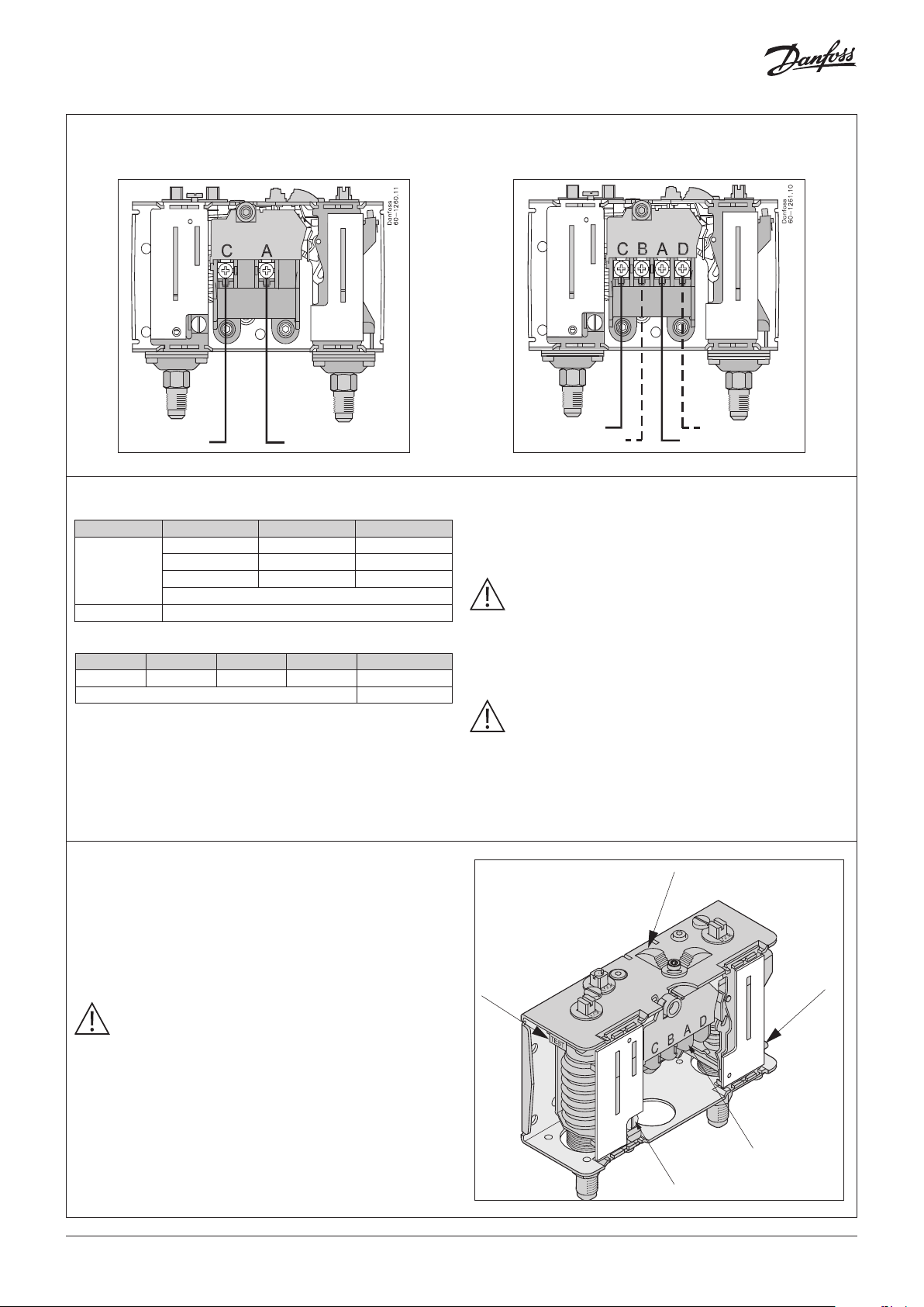
Wiring Option A:
Danfoss
60-1262f.11
– KPU 15 Pressure Switch (SPST (NO + NC))
Wiring Option B:
– KPU 16 Pressure Switch (SPDT with LP/HP signal)
LOAD ~ LINE
Wiring
Electrical ratings according to UL regulations
Contacts Motor ratings 120 V AC 240 V AC
A – B
A – C
A – D Pilot Duty 50 VA, 240 V AC
European electrical ratings according to EN 60947
AC1 AC3 AC15 LR DC13
16 A 16 A 10 A 112 A 12 W
The terminal block as well as grounding screw are accessible
after dismounting of the front cover.
Contact function test (Manual trip)
When the electrical leads are connected the contact function
can be manually tested regardless of pressure conditions in the
system. For LP side testing use the trip lever located in the left
side of the dual KPU. The lever must be operated with ngers
only. Do not use screwdriver as it will damage the switch. For HP
side testing use lever located at bottom of right side of the dual
KPU. The lever must be carefully operated with a screwdriver.
NOTE:
While operating the manual trip on KPU switches with
manual reset it is necessary to push the reset knob.
FLA 24 24
AC LRA make only 14 4 14 4
NIA 24 24
Pilot Duty 12 W, 120/240 V DC
400 V 220 V
LOAD
LP signal
HP signal
~ LINE
Wire dimensions: 10 AWG max.
Cable entry: 7⁄8 inch cable entry for 1⁄2 inch male pipe thread
connection (conduit boss) or similar (Pg 13.5 or Pg 16) screwed
cable entry.
CAUTION:
Disconnect power supply before wiring connections
are made or service to avoid possible electrical shock or
damage to equipment.
Do never touch live parts with your ngers or with
anytool.
NOTE:
All wiring should conform to the National Electrical Code
and local regulations.
Use copper wire only.
Use terminal screws furnished in the contact block.
Do not exceed tightening torque 20 lb. in (2.3 Nm).
Do not exceed electrical ratings for the switch.
A
E
B
A: Manual reset button (available only on switches with manual/
convertible reset function)
B: HP Manual trip. Press the lever up. Use screwdriver only!
C: Terminal block
D: Grounding screw
E: LP Manual trip. Press the lever up. Use ngers only!
© Danfoss | DCS (jmn) | 2017.01
C
D
DKRCC.PI.CD0.C6.02 | 520H11521 | 3
Page 4
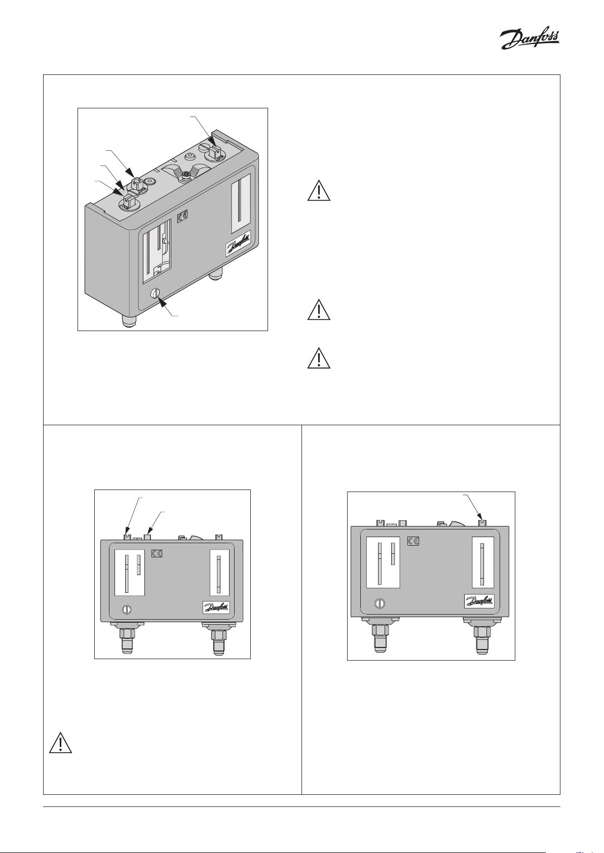
Adjustment
60-1265f.11
60-1264f.11
60-1263.11
D
E
Before adjustment, loosen the locking plate.
For setting use the Universal Refrigeration Wrench.
Set Cut In/ Cut Out by adjusting range screw:
A
– On LP Side turn the range screw clockwise to lower theCut In.
– On HP Side turn the range screw clockwise to rise theCutOut.
C
Danfoss
Set dierential by adjusting dierential screw:
– On LP Side turn the dierential screw clockwise to increase the
dierential.
NOTE:
Adjust the pressure switch with settings specied by the
manufacturer of the controlled equipment.
Do not exceed the pressure ratings of the controlled
equipment or any of its components when checking
pressure switch operation or operating the controlled
equipment.
Do not adjust pointers beyond the highest or lowest
indicator marks on the scale plate, as this may cause
inaccurate swich operation.
B
A: HP Range adjusting screw
B: Cover screw
C: LP Dierential adjusting screw
D: Locking plate
E: LP Range adjusting screw
Low Pressure Side Setting
Cut Out on pressure fall.
Scale plate directly indicates the Cut In
and the Dierential set points.
1
2
IMPORTANT:
The scale plate is only for reference and for more
precise setting a pressure gauge should be used.
IMPORTANT:
After installing and adjusting pressure switch run the
controlled equipment several times (at least three
cycles) at normal operating conditions.
High Pressure Side Setting
Cut Out on pressure rise.
Scale plate directly indicates the Cut Out set point.
There is no pointer for the Dierential.
The Dierential pressure value is xed and printed on the scale
plate.
1
Danfoss
Danfoss
1. Turn the range screw to adjust the Cut In set point.
2. Then turn the dierential screw to adjust the Dierential
3. The Cut Out setting equals the Cut In less the Dierential:
CUT OUT = CUT IN - DIFFERENTIAL
NOTE:
Cut Out set point must be above absolute vacuum!
If the Dierential is set too high then the switch will
not stop the compressor.
4 | 520H11521 | DKRCC.PI.CD0.C6.02
1. Turn the range screw to adjust the Cut Out set point.
2. The Cut In setting equals the Cut Out less the Dierential:
CUT IN = CUT OUT - 60 psi
© Danfoss | DCS (jmn) | 2017.01
 Loading...