

User Manual
PLUS+1® Compliant
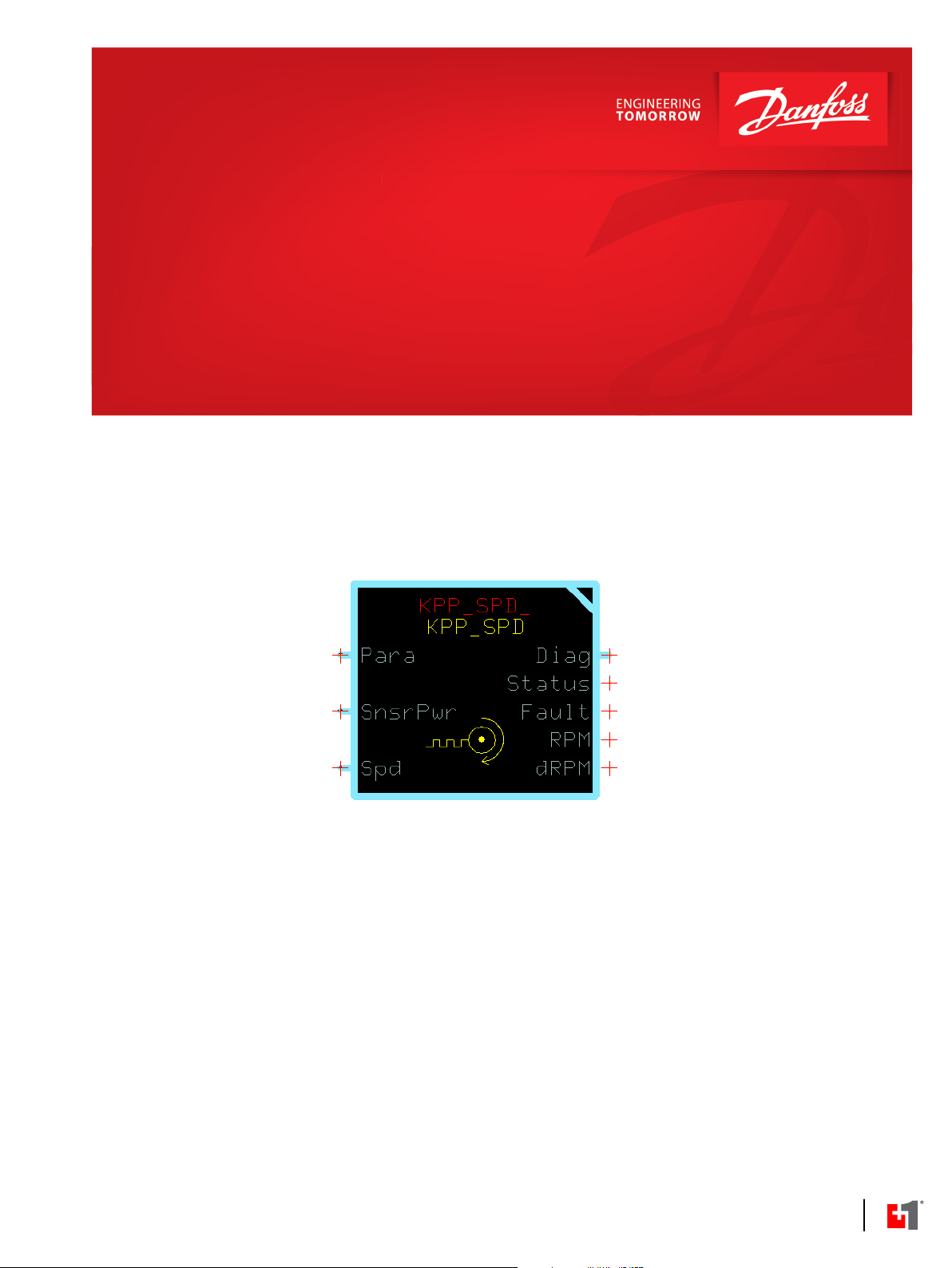
KPP_SPD Speed Sensor Function Block
www.danfoss.com

User Manual
PLUS+1® Compliant KPP_SPD Speed Sensor Function Block
Revision history Table of revisions
Date Changed Rev
January 2019 Rebranding 0103
November 2011 BA
2 | © Danfoss | January 2019 11022915 | AQ00000070en-000103

User Manual
PLUS+1® Compliant KPP_SPD Speed Sensor Function Block
Contents
KPP_SPD Function Block
Inputs....................................................................................................................................................................................................4
Function Block Parameter Values...............................................................................................................................................4
Outputs................................................................................................................................................................................................ 5
Function Block Connections.........................................................................................................................................................5
Using Namespaces...........................................................................................................................................................................5
Change Namespace Value.......................................................................................................................................................6
Include Advanced Checkpoint with Namespace in Compiled Application...........................................................6
Status and Fault Logic.....................................................................................................................................................................7
Status Logic........................................................................................................................................................................................ 7
Fault Logic...........................................................................................................................................................................................7
Fault Reporting Examples........................................................................................................................................................8
Speed Sensor 1 Fault Detection....................................................................................................................................... 8
Speed Sensor 2 Fault Detection....................................................................................................................................... 8
Legacy MC Controller—Input Configuration.........................................................................................................................9
Configure the MFIn..................................................................................................................................................................10
SC and Non-Legacy MC Controller—Input Configuration..............................................................................................10
Configure the MFIn..................................................................................................................................................................10
Customizable Service Screens...................................................................................................................................................11
Pre-Made Service Screen for Speed Sensor Function Block......................................................................................11
Pre-Made Service Screen Panel Components for Speed Sensor Function Block.............................................. 13
©
Danfoss | January 2019 11022915 | AQ00000070en-000103 | 3
User Manual
PLUS+1® Compliant KPP_SPD Speed Sensor Function Block
KPP_SPD Function Block
The KPP_SPD function block outputs an RPM signal that is based on inputs from a KPP speed sensor.
This function block receives its Spd input through MFIn.
Inputs
Inputs to the function block are described.
Input Type Range Description
Para —— —— Input for a user-defined Pulse/Rev value that defines the number of pulses equal to one
revolution.
Optionally, inputs a:
FaultDetTm value that replaces the function block’s internal default fault-direction time.
DirLockHz value that replaces the function block's internal default fault direction-lock frequency.
SnsrPwr —— —— Reports sensor power supply voltage.
Spd —— —— Speed signal from the speed sensor.
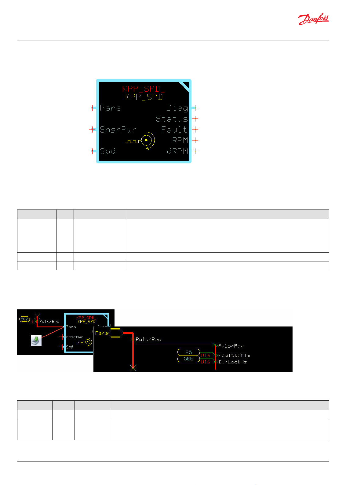
Function Block Parameter Values
The para bus input signals, which set the KPP_SPD function block's operating characteristics, are
described.
The input signals of the Para bus set the function block’s operating characteristics. The Puls/Rev value is
specified outside of the function block for the specific sensor used. Typically, you do not have to change
any of the other values for the correct operation of the function block.
Input Type Range Description
Puls/Rev U16 1–600 Sets the conversion factor that is used to convert the measured frequency from Hz to RPM.
FaultDetTm U16 0-65535 Sets the delay time before the function block:
– Reports a detected fault.
– Clears a reported fault that is no longer detected.
4 | © Danfoss | January 2019 11022915 | AQ00000070en-000103
User Manual
PLUS+1® Compliant KPP_SPD Speed Sensor Function Block
KPP_SPD Function Block
Outputs
Outputs of the function block are described.
Output Type Range Description
Diag —— —— Outputs a Diag bus that has a:
•
Para sub-bus.
•
FltTmrFreq signal.
Also has a Checkpoints page which you can set to enable advanced checkpoint with
namespace components. This makes all of the function block's input, output, and internal
signals available to the Service Tool.
Status U16 —— Reports the function block’s status conditions.
Fault U16 —— Reports the function block’s fault conditions.
RPM U32 0–9000000 rpm The calculated rpm.
1—1.0 rpm.
dRPM U32 0–9000000 x .1 Legacy signal, previously labeled RPM in version 1.03 and earlier.
10—1.0 rpm.
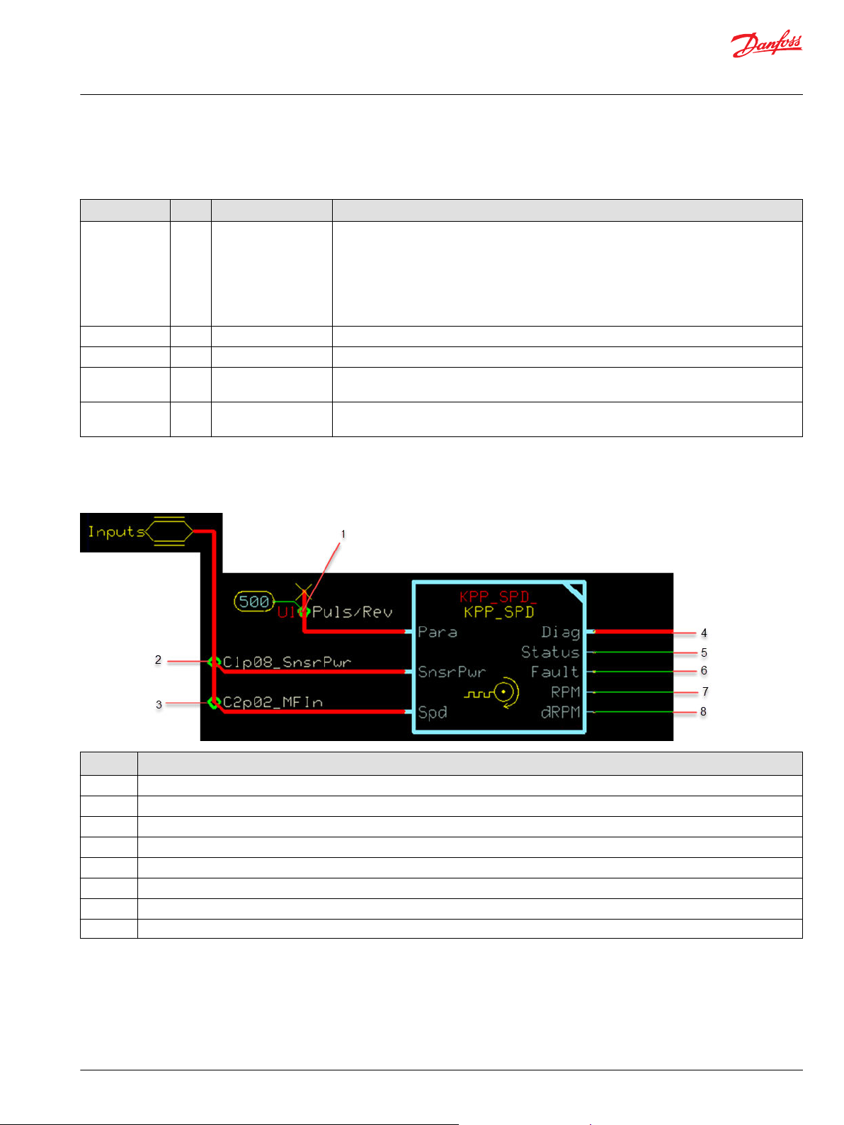
Function Block Connections
Connections you can make with the KPP_SPD function block are described.
Item Description
1 Pulses per revolution value.
2 Sensor power supply voltage.
3 Sensor speed.
4 Diagnostic signals.
5 Function block status.
6 Function block faults.
7 RPM output.
8 dRPM output.
Using Namespaces
Namespaces can help you successfully compile an application that uses the same function block more
than once.
Change each function block's namespace by setting its Namespace value to something unique. If you do
not change the Namespace value, you cannot compile the application.
©
Danfoss | January 2019 11022915 | AQ00000070en-000103 | 5

User Manual
PLUS+1® Compliant KPP_SPD Speed Sensor Function Block
KPP_SPD Function Block
The Namespace value adds a unique prefix to each component name.
Also, if you want to use these function blocks' companion Service Tool screens, you must include the
function block's advanced checkpoint with namespace in the application's compiled .lhx file. Use the
function block's Checkpoints page to include the checkpoint.
Change Namespace Value
To successfully compile your application, change the namespace value for function blocks that are used
more than once in an application.
1. In the PLUS+1® GUIDE menu bar, click the Query/Change button.
2. Click on the function block whose namespace you want to set to a unique value.
The Edit Page window opens.
3. In the Edit Page window, enter a meaningful Namespace value.
Namespace values are case-sensitive.
•
To save controller memory, use a short namespace value.
•
4. Press Enter.
5. Repeat these steps to enter unique namespace values for other identical function blocks.
Include Advanced Checkpoint with Namespace in Compiled Application
Make all of a function block's input, output and internal signals available to the Service Tool.
Each function block has an Advanced Checkpoint with Namespace page that you can edit to ensure
unique namespaces are included in the application's companion screens for the Service Tool.
1. Enter the function block.
2. On the Checkpoints CP page, ensure the Chkpt signal is set to T.
3. To set the value to true:
a) Select the chkpt signal.
The Edit Value window opens.
b) Select T from the drop-down menu.
6 | © Danfoss | January 2019 11022915 | AQ00000070en-000103

User Manual
PLUS+1® Compliant KPP_SPD Speed Sensor Function Block
KPP_SPD Function Block
Status and Fault Logic
Use status and fault codes to determine proper program operation. The function block does not use
standard status and fault codes.
Status Logic
The status code indicates the calibration state of the function block.
Status Bit*Reported While
Invalid setup/calibration 4 The Input Para bus Puls/Rev signal has been assigned a value outside a range of 1–600.
*
Position of set bit in a 16 bit status or fault code. Bit 1 is the least significant bit.
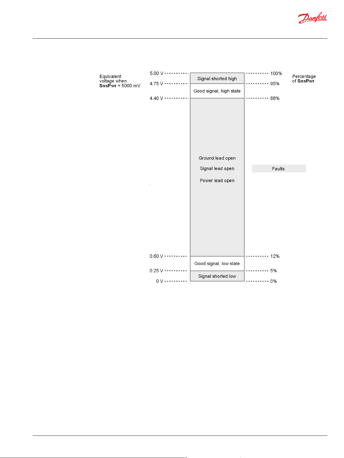
Fault Logic
A frequency input signal is compared with sensor power voltage to detect faults.
The voltage level of the frequency input signal is measured as a percent of sensor power voltage. This
measurement is used to detect faults.
The function block detects and reports fault conditions and applies constraints. The sensor power and
frequency range fault conditions in this block are reported immediately upon detection and clear
immediately when the condition is no longer detected.
Frequency signal faults are detected while Freq = 0 or when Count = 0. (The bus routed to the function
block’s Spd input contains the Freq and Count signals.) Detected faults are reported in the Fault output
value from the time the count reaches FaultDetTm until it counts back down to zero.
Problems that can occur in the function block are described in the table that follows, along with potential
solutions to these problems.
Fault Cause Bit Response Correction
Sensor power
voltage too low.
Sensor power
voltage too high.
Measured
frequency too low.
Measured
frequency too
high.
Frequency signal
voltage too low.
Frequency signal
voltage too high.
Frequency signal
open.
Frequency ground
signal open.
Frequency power
signal open.
*
Position of set bit in a 16 bit status or fault code. Bit 1 is the least significant bit.
‡
Vpct represents an input voltage as a percent of the sensor.
SnsPwrVolt < 4500 mV. 1
SnsPwrVolt > 5250 mV. 2
Freq 3
Freq > 10000 Hz. 4
Vpct‡ < 3%
Vpct‡ > 97%
37% ≤ Vpct‡ ≤ 63%
63% ≤ Vpct‡ ≤ 85%
15% ≤ Vpct‡ ≤ 37%
*
*
*
*
*
5
*
6
*
7
*
8
*
9
Vpct‡ calculated as percent of
4500.
Vpct‡ calculated as percent of
5250.
RPM signal = 0. Correct the application program to provide a U16 value
RPM signal equivalent to
10000Hz.
No response detected only
while Freq = 0 Hz.
No response detected only
while Freq = 0 Hz.
No response detected only
while Freq = 0 Hz.
No response detected only
while Freq = 0 Hz.
No response detected only
while Freq = 0 Hz.
Correct the sensor supply voltage.
Correct the sensor supply voltage.
type for the Freq input signal in the Spd bus.
Check for any hardware issues that could cause an
invalid frequency value, such as electrical noise. Verify
that the speed sensor is producing a valid signal.
Make sure the speed signal is not shorted to SnsPwr.
Verify that the speed signal is not shorted to ground.
Make sure the speed signal is connected.
Make sure the speed sensor ground wire is connected.
Make sure the speed sensor power wire is connected.
©
Danfoss | January 2019 11022915 | AQ00000070en-000103 | 7

User Manual
PLUS+1® Compliant KPP_SPD Speed Sensor Function Block
KPP_SPD Function Block
Fault Reporting Examples
Use the examples that follow to learn more about how the function block detects and reports faults.
Speed Sensor 1 Fault Detection
This example shows how a set of five faults is reported using a fault timer.
The fault timer counts up to FaultDetTm while any fault in the set is detected. The fault time counts
down to zero while no fault in the set is detected.
Speed Sensor 1 Fault Detection
Speed Sensor 2 Fault Detection
This example shows how a set of three faults is reported for each input signal, with each signal using its
own fault timer.
The fault timers count up to FaultDetTm while any fault in the set is detected and counts down to zero
while no fault in the set is detected.
8 | © Danfoss | January 2019 11022915 | AQ00000070en-000103
User Manual
PLUS+1® Compliant KPP_SPD Speed Sensor Function Block
KPP_SPD Function Block
Speed Sensor 2 Fault Detection
Unlike speed sensor 1 faults, speed sensor 2 faults do not distinguish between a ground fault, a signal
fault, or a power lead open fault. If you get one of these faults, check all three leads to determine which
lead is causing the fault.
Legacy MC Controller—Input Configuration
Learn how to configure Spd input.
You route the function block’s Spd input through the MFIn.
You must change the MFIn to accept the input.
©
Danfoss | January 2019 11022915 | AQ00000070en-000103 | 9

User Manual
PLUS+1® Compliant KPP_SPD Speed Sensor Function Block
KPP_SPD Function Block
Configure the MFIn Learn how to configure the MFIn to accept input from the KPP_SPD function block.
1. In the GUIDE template, enter the Inputs page.
2. Enter the MFIn that receives the input.
3. Make the changes shown in the following figure.
SC and Non-Legacy MC Controller—Input Configuration
You route this function block’s Spd input through MFIn.
You must change the default configuration of the MFIn to accept the inputs.
The MFIn that you use must be capable of Freq input and have configurable Bias, Range, and
InputMode values.
Configure the MFIn
Learn how to configure MFIn to accept input from the function block.
The MFIn that you use must be capable of a Freq input and have configurable Bias, Range, and
InputMode values.
1. In the GUIDE template, enter the Inputs page.
2. Enter the MFIn page that receives the input.
10 | © Danfoss | January 2019 11022915 | AQ00000070en-000103

User Manual
PLUS+1® Compliant KPP_SPD Speed Sensor Function Block
KPP_SPD Function Block
3. Make the changes that are shown in the following figure.
Customizable Service Screens
This function block comes with pre-made service screens that you can customize when building your
Service Tool application.
The pre-made screens simplify the task of creating Service Tool applications. You can use the screens as
is. Or, you can choose screen components to place in your application.
Refer to the PLUS+1® GUIDE Service Tool Design Manual (Danfoss document number L1320837) for more
information on how to create Service Tool screens.
Pre-Made Service Screen for Speed Sensor Function Block
This topic describes a large pre-made screen that you can use in your Service Tool application.
©
Danfoss | January 2019 11022915 | AQ00000070en-000103 | 11

User Manual
PLUS+1® Compliant KPP_SPD Speed Sensor Function Block
KPP_SPD Function Block
Item Description
Count
Speed The speed that the sensor measures, in RPM.
Speed Hi Res
Frequency
Frequency Voltage The measured voltage of the speed signal.
Sensor Supply The power supply to the sensor in amps.
Pulses Per Rev
Fault Detect Time
Freq OOR Timer The frequency out of range timer, which is a counter used for fault detection and fault clearing.
Volt Fault Timer The measured voltage of the direction signal that is used for direction and fault detection. The times is the fault delay counter for
Status
Fault If a fault occurs, the value of the fault appears, and the condition of the item producing the fault changes from OK to Active.
Pulses for each update, the number of measured edges.
Measured speed, reported with greater accuracy.
Measured frequency, which is converted into speed.
A measurement of how many pulses of frequency indicate one revolution of the motor or pump.
The time, in ms, that a fault can be set or a fault can be cleared.
the frequency input signal.
If a parameter value is out of range, the function block reports this, and the status code 0x0008 appears.
If all parameter values are in range, the status code 0x0000 appears.
0x0001 Sensor power voltage is too low (less than 4500 mV.) Correct the supply voltage.
0x0002 Sensor power voltage is too high (greater than 5250 mV.) Correct the supply voltage.
0x0004 Measured frequency for Freq input signal on the Spd bus is too low.
0x0008 Measured frequency for the Freq input signal on the Spd bus is too high.
0x0010 Frequency signal voltage is too low. Make sure the speed signal is not shorted to SnsPwr.
0x0040 Frequency signal is open. Make sure the speed signal is connected.
0x0020 Frequency signal voltage is too high. Verify that the speed signal is not shorted to ground.
0x0080 Frequency ground signal is open. Make sure the speed sensor ground wire is connected.
0x0100 Frequency power signal is open. Make sure the speed sensor power wire is connected.
12 | © Danfoss | January 2019 11022915 | AQ00000070en-000103

User Manual
PLUS+1® Compliant KPP_SPD Speed Sensor Function Block
KPP_SPD Function Block
Pre-Made Service Screen Panel Components for Speed Sensor Function Block
This topic describes pre-made components that you can use to quickly build a Service Tool application
for the function block.
Item Description
Frequency
Speed The speed that the sensor measures, in RPM.
Pulses Per Rev
Status
Fault If a fault occurs, the value of the fault appears, and the condition of the item producing the fault changes from OK to Active.
Measured frequency, which is converted into speed.
A measurement of how many pulses of frequency indicate one revolution of the motor or pump.
If a parameter value is out of range, the function block reports this, and the status code 0x0008 appears.
If all parameter values are in range, the status code 0x0000 appears.
0x0002 Sensor power voltage is too high (greater than 5250 mV.) Correct the supply voltage.
0x0004 Measured frequency for Freq input signal on the Spd bus is too low.
0x0008 Measured frequency for the Freq input signal on the Spd bus is too high.
0x0010 Frequency signal voltage is too low. Make sure the speed signal is not shorted to SnsPwr.
0x0020 Frequency signal voltage is too high. Verify that the speed signal is not shorted to ground.
0x0040 Frequency signal is open. Make sure the speed signal is connected.
0x0080 Frequency ground signal is open. Make sure the speed sensor ground wire is connected.
0x0100 Frequency power signal is open. Make sure the speed sensor power wire is connected.
©
Danfoss | January 2019 11022915 | AQ00000070en-000103 | 13

Danfoss
Power Solutions GmbH & Co. OHG
Krokamp 35
D-24539 Neumünster, Germany
Phone: +49 4321 871 0
Danfoss
Power Solutions ApS
Nordborgvej 81
DK-6430 Nordborg, Denmark
Phone: +45 7488 2222
Danfoss
Power Solutions (US) Company
2800 East 13th Street
Ames, IA 50010, USA
Phone: +1 515 239 6000
Danfoss
Power Solutions Trading
(Shanghai) Co., Ltd.
Building #22, No. 1000 Jin Hai Rd
Jin Qiao, Pudong New District
Shanghai, China 201206
Phone: +86 21 3418 5200
Products we offer:
Hydro-Gear
www.hydro-gear.com
Daikin-Sauer-Danfoss
www.daikin-sauer-danfoss.com
DCV directional control
•
valves
Electric converters
•
Electric machines
•
Electric motors
•
Hydrostatic motors
•
Hydrostatic pumps
•
Orbital motors
•
PLUS+1® controllers
•
PLUS+1® displays
•
PLUS+1® joysticks and
•
pedals
PLUS+1® operator
•
interfaces
PLUS+1® sensors
•
PLUS+1® software
•
PLUS+1® software services,
•
support and training
Position controls and
•
sensors
PVG proportional valves
•
Steering components and
•
systems
Telematics
•
Danfoss Power Solutions is a global manufacturer and supplier of high-quality hydraulic and
electric components. We specialize in providing state-of-the-art technology and solutions
that excel in the harsh operating conditions of the mobile off-highway market as well as the
marine sector. Building on our extensive applications expertise, we work closely with you to
ensure exceptional performance for a broad range of applications. We help you and other
customers around the world speed up system development, reduce costs and bring vehicles
and vessels to market faster.
Danfoss Power Solutions – your strongest partner in mobile hydraulics and mobile
electrification.
Go to www.danfoss.com for further product information.
We offer you expert worldwide support for ensuring the best possible solutions for
outstanding performance. And with an extensive network of Global Service Partners, we also
provide you with comprehensive global service for all of our components.
Local address:
Danfoss can accept no responsibility for possible errors in catalogues, brochures and other printed material. Danfoss reserves the right to alter its products without notice. This also applies to products
already on order provided that such alterations can be made without subsequent changes being necessary in specifications already agreed.
All trademarks in this material are property of the respective companies. Danfoss and the Danfoss logotype are trademarks of Danfoss A/S. All rights reserved.
©
Danfoss | January 2019 11022915 | AQ00000070en-000103
 Loading...