

Page 1
it Specication
KPPG4B7XX
Hall Eect Pulse Pickup
3500 Annapolis Lane North, Minneapolis, MN 55447
Telephone: (763) 509-2084 Fax: (763) 559-0108
www.danfoss.com
General Description
The KPPG4B7XX is a sealed xed position, Hall eect pulse pickup. It is intended for use in Series 51-1 and Series 51 variable
motors. The KPPG4B7XX is not capable of being powered directly from a battery because of the voltage transients (voltage
spik
e above 15 volt) that may cause permanent damage. Battery voltage transients are a common occurrence with 12 or 24 V
systems. A regulated supply power of 4.5 to 8.5 Vdc is required. This device will be used typically for speed detection and has
wire fault detection.
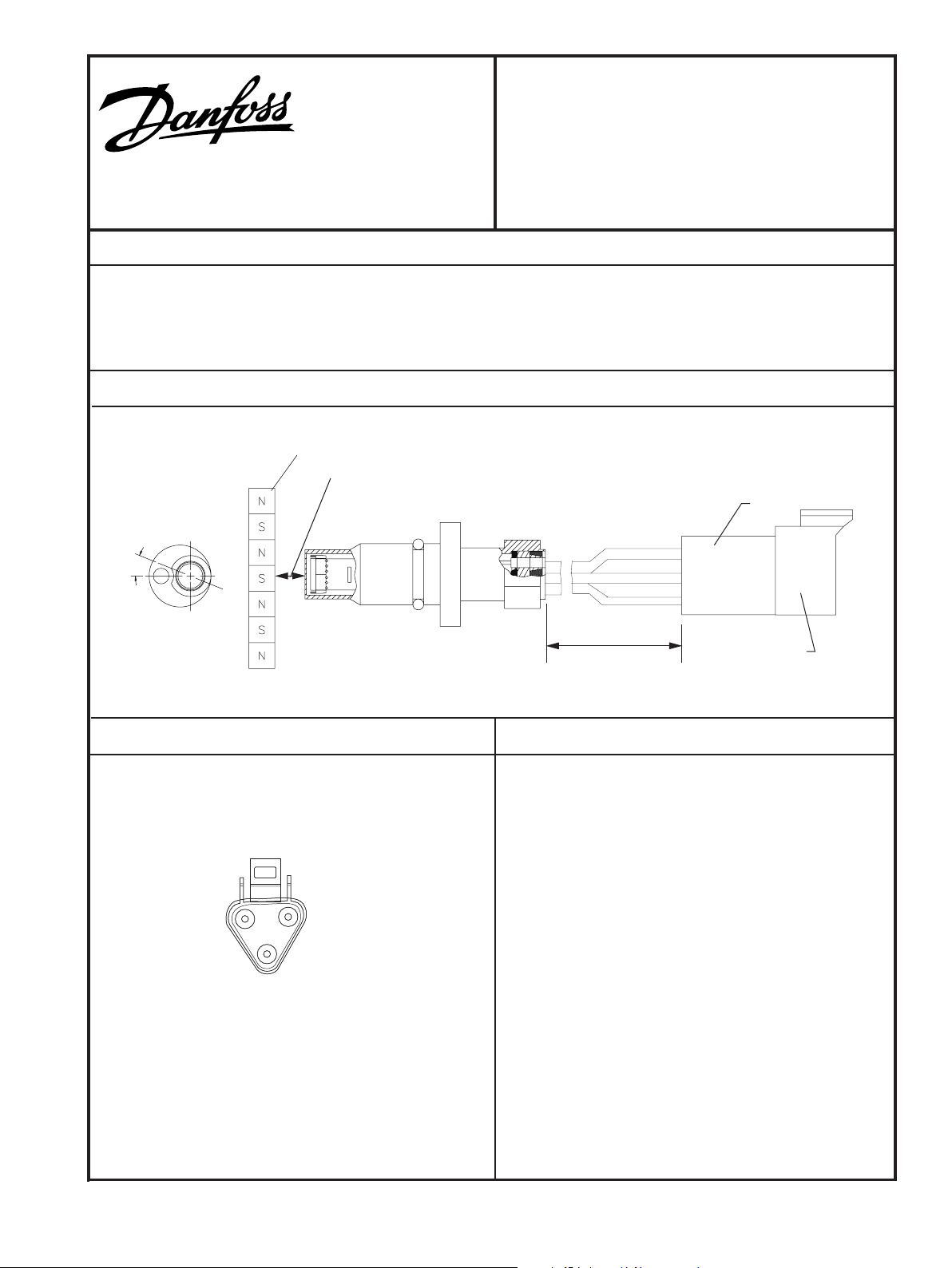
Dimensions
Dimensions of the KPPG4B7XX in millimeters [inches]..
Speed ring
22°
Air gap 1.52 [0.060] maximum
(approximately 1/2 to 1 turn of thread)
Receptacle
Red
White
Black
Electrical Connection
Pin orientation of the mating 3 pin Deutsch® Plug DT Series
connector. (Danfoss part number K22335).
White wire:
B
Speed Signal
C
Black wire:
Ground Common
A
Red wire:
Power +
2139
Variable
Electrical connection
Electrical Characteristics
Supply voltage
Battery 4.5 t
Output voltage in high state
Supply voltage minus 0.5 Vdc
Output voltage in low state
0.5 Vdc, maximum (no load)
aximum frequency
M
5 kHz
1
Maximum operation current
20 mA at
Load
5 kΩ to both ground and supply
1
Peak reverse voltage
15 Vdc continuous
-
o 8.5 Vdc
, minimum (no load)
1 kHz
2397
Peak transient voltage
±80 Vdc for 2 ms
11017581 · Rev A · Oct 2006
© Danfoss, 2013-09 11017581 · Rev A · Oct 2006 1
© Copy
Page 2

Installation
1. Turn in clockwise by hand until bottom end gently touches the speed ring.
2. Back out counterclockwise 1/4 turn. Continue backing out until the ats are 22
(20º to 30º is acceptable). Do not back out the KPP more than 3/4 of a turn from touching.
3. U
sing a 1/2 inch wrench to hold the KPP pulse pickup, torque the lock nut to 13 N•m (1
º either side of pump or motor shaft centerline
0 ft•lb) with an 11/16 inch wrench.
Troubleshooting
Tools required to perform the following steps: A volt ohm meter (VOM) set to read DC volts.
1. Ensure the KPP pulse pickup is installed correctly. See Installation, on this page.
2. Check for proper supply voltage (4.5 to 8.5 Vdc) with a VOM across the red and black connections (pins A and B).
3. Check for speed output using a VOM across the black and white connections (pins C and B). Turn pump or motor very slowly
by hand or check output just as the prime mover is coming to a stop. Note a voltage pulse at meter. It will likely be dicult
to read exactly, therefore simply note a pulse (approximately 60 pulses per revolution). If there is no indication of a pulse,
replace the KPP pulse pickup.
11017581 · Rev A · Oct 2006
© Danfoss, 2013-09 11017581 · Rev A · Oct 2006 2
 Loading...