

Page 1
Installation Guide
Electronic Heat Cost Allocator INDIV-X-10V, INDIV-X-10W Radio
0.0 Table of Contents
1. General.......................................3
1.1 Introduction.............................................3
1.2 Application..............................................3
2. Specification ..................................4
2.1 General Description .....................................4
2.1.1 Type ....................................................4
2.1.2 Design ..................................................4
2.1.3 Characteristics...........................................4
2.1.4 Display ..................................................5
2.1.5 Electronics ..............................................5
2.1.6 Versions.................................................5
2.1.7 Optical Interface.........................................5
2.1.8 Radio Transmission ......................................5
2.2 Operating mode.........................................6
2.2.1 Cycle Time...............................................6
2.2.2 Single Sensor Version with Start Sensor...................6
2.2.3 Double Sensor Version...................................6
2.2.4 Comparison of the Measuring Principles..................7
2.2.5 Temperature Measurement and Calculation ..............7
2.2.6 Calculation of the Displayed Consumption Value .........8
2.2.7 Start of Counting ........................................9
2.3 Display and Additional Functions .......................10
2.3.1 The Menu Sequences of the Digital Display..............10
2.3.2 The Digital Displays.....................................12
2.3.3 Rolling Digital Display ..................................15
2.3.4 Energy-Saving Night Mode between 20.00 and 6.00 h ...16
2.3.5 Communication Indicator ..............................16
2.3.6 Real Time Clock and Calendar ...........................16
2.3.7 Readout................................................17
2.3.8 Check Code ............................................17
2.3.9 Change of Battery ......................................18
2.3.10 Protection against Outside Influences . . . . . . . . . . . . . . . . . . .18
2.4 Special Functions.......................................19
2.4.1 Suppression of Summer Counting.......................19
2.4.2 Programmable Start Temperature of
Summer and Winter period .............................19
2.4.3 Annual Reset of the Values..............................19
2.4.4 Unit Scale and Product Scale ............................19
2.5 Parameterisation .......................................21
2.6 Error ...................................................21
2.6.1 Description of the Function Control .....................21
2.6.2 List of Errors ............................................22
2.7 Radio Standby – Radio-HCA INDIV-X-10W ...............22
2.7.1 Sleeping Mode .........................................22
2.7.2 Installation Mode .......................................22
2.7.3 Operation Mode........................................23
3. Installation ..................................24
3.1 Introduction............................................24
3.2 DIN Standard Requirements for the Installation..........24
3.3 General Restrictions ....................................25
3.4 Operating Range .......................................25
3.5 Installation to the Radiator..............................26
3.6 Wall-Mounting .........................................27
3.7 Installation of Fastening-Parts Kits.......................28
3.7.1 Installation to Sectional Radiator ........................28
3.7.2 Wall-Mounting - Sectional Radiator .....................28
3.7.3 Installation to Folded Radiator ..........................29
3.7.4 Wall-Mounting – Folded Radiator .......................30
3.7.5 Installation to Panel-Type Radiator ......................31
3.7.6 Wall-Mounting - Panel-Type Radiator....................32
3.7.7 Installation to Panel-Type Radiator
with Front Convection Plate.............................33
3.7.8 Bathroom radiator – Towel rails .........................34
3.7.9 Sectional radiator wide .................................35
3.8 Overview mounting accessories.........................36
3.9 Mounting and Sealing ..................................37
4. Commissioning ..............................38
5. Readout .....................................39
5.1 Manual Readout ........................................39
5.2 Readout over the Optical Interface ......................39
5.2.1 Optical Probe...........................................39
5.2.2 Transmission Protocol ..................................39
5.2.3 Timing of the Optical Interface ..........................40
5.2.4 Frames of the Optical Readout ..........................41
5.2.5 Remote Radio Readout .................................43
5.2.6 Stationary Readout . . . . . . . . . . . . . . . . . . . . . . . . . . . . . . . . . . . . . 44
Danfoss Heating VIIGC102
1
Page 2

Installation Guide Electronic Heat Cost Allocator INDIV-X-10V, INDIV-X-10W Radio
0.0 Table of Contents
5.2.7 Timing of Radio Transmission ...........................44
5.2.8 Frame of the Radio Transmission ........................45
6. Rating factors ................................46
6.1 Taking Measurements ..................................46
6.1.1 Rating of Radiators of Over Length or
High Nominal Output...................................46
6.1.2 Rating of Radiator ......................................47
6.2 Table of Rating factors ..................................48
7. Technical Data ...............................50
7.1 Dimensional Drawing...................................51
8. Enclosure ....................................52
8.1 Enclosure 1.............................................52
8.2 Enclosure 2.............................................53
8.3 Temperature Limits acc. to EN 834.......................54
8.4 Calculation of Temperature – Interpolation Table ........55
8.5 Rating factors acc. to EN 834 ............................56
2
VIIGC102 Danfoss Heating
Page 3

Installation Guide Electronic Heat Cost Allocator INDIV-X-10V, INDIV-X-10W Radio
1. General
1.1 Introduction
This installation guide is used for the users and the service
personnel of the Danfoss heat cost allocators. It describes the
handling of the heat cost allocator INDIV-X-10V and the radio heat
cost allocator INDIV-X-10W. Since the measuring functions are the
same for both heat cost allocators the descriptions in this guide
apply for both versions. In case of deviations, a special note is
made to this end.
Primarily, the installation of the heat cost allocator to the most
common radiator types is described. Apart from the information
on the installation of the heat cost allocator, basic information
(rating of heat cost allocators) is given and special features of our
devices (design, function, installation) are described in this guide
as well.
1.2 Application
The heat cost allocator is an accessory measuring device to record
the heat output of radiators in units.
Units are apartments, office-, and business-, commercial or
industrial premises where the heat is supplied by a conjoint
central heating system or via a conjoint district heating station.
The entity of the units forms a billing unit.
If one billing unit consists of units with typical differences (e.g.
technical differences such as different heating systems or different
consumptions of e.g. industrial premises and apartments), a
sub-division of the billing unit in unit groups may be necessary.
Each radiator is equipped with a heat cost allocator which
records and assesses the heat output of the radiator and displays
the consumption value. The consumption value is the basis for
allocating the heating costs to each unit which is necessary for the
annual billing of the heating costs.
Danfoss Heating VIIGC102
33
Page 4
Installation Guide Electronic Heat Cost Allocator INDIV-X-10V, INDIV-X-10W Radio
2. Specification
2.1 General Description
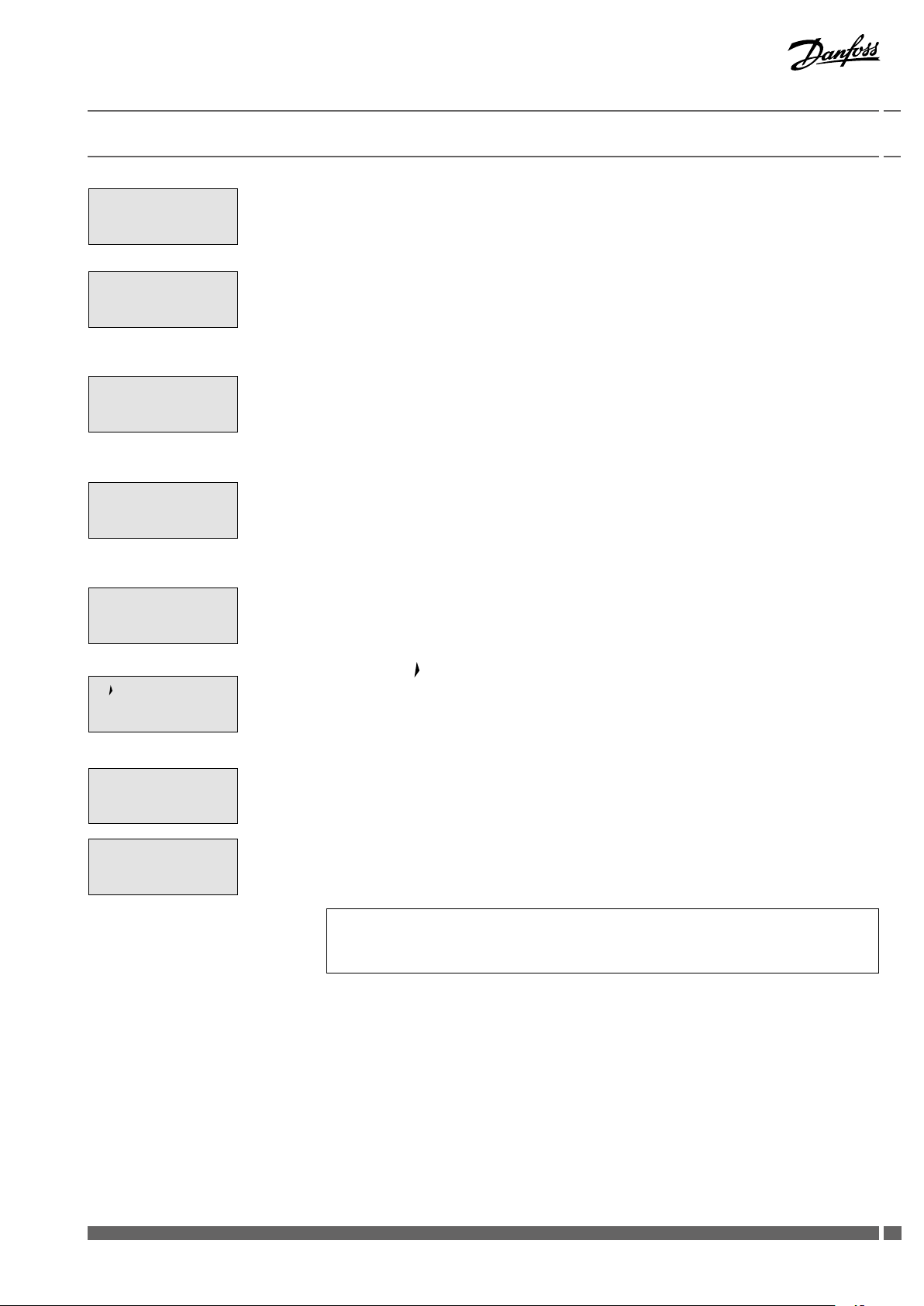
2.1.1 Type
The electronic heat cost allocators Danfoss INDIV-X-10V / INDIVX-10W operate either according to the single sensor principle
with start sensor or the double sensor principle. The device has
been developed and approved in accordance with the European
Standard EN 834:2013.
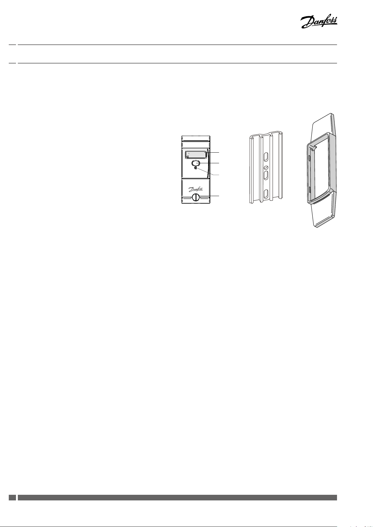
2.1.2 Design
The heat cost allocator consists of a microprocessor, a lithium
battery, two temperature sensors, a heat conducting aluminium
back plate, a multi-functional display and a plastic housing.
The measuring circuit consists of the temperature sensors,
the analogue-digital conversion, the reference resistance
for standardising the measuring transformation and the
microprocessor for accessing the radiator heat output. During
each measuring the circuit tolerances are eliminated with a
reference resistance and the heat cost allocator carries out an
automatic self-test.
2.1.3 Characteristics
• Measuring by two temperature sensors, radiator and ambient
temperature sensor (NTC-resistor)
• Optional measuring principle: 1 sensor mode with start sensor
or two sensor mode
• Unit scale or product scale
• Recording of cumulated heat consumption on the annual set
day
• Recording of 36 monthly values or 18 monthly and half monthly
values
• Optical interface for the readout of the data and programming
• Readout via radio optional with a mobile radio modem or
directly by the billing office over the radio central installed
outside the unit
• User-friendly operation by push button
• 6-digit and high-contrast LCD display
• Check code for postcard mail-in method
• Remote sensor version with 1.5 m cable
• Standard aluminium back plate for nearly all existing bolts with
common dimensions and installation possibilities – thus easy
installation (no cutting and welding of bolts necessary)
• Snap-on blind to cover colour shadows for increased aesthetics
• Safe operation and fraud detection
• Factory seal protecting against unauthorized manipulation
• Possibility to use seal sticker as second seal for further
protecting against manipulation
• Lithium battery with a capacity of up to 10+1 years
• Meets EN 834:2013.
::
LCD-Display
Optical
Interface
Push Button
Seal
Standard aluminium
back plate for nearly
all existing bolts with
common dimensions
and mounting
possibilities – thus
easy installation.
Snap-on blind
to cover colour
shadows for
increased
aesthetics.
4
VIIGC102 Danfoss Heating
Page 5

Installation Guide Electronic Heat Cost Allocator INDIV-X-10V, INDIV-X-10W Radio
2. Specification
2.1.4 Display
The heat cost allocator has a LCD-display with 6 large main digits
on the right and 2 smaller digits on the left as well as two special
symbols and one communication indicator. The main digits are
separated by four decimal points. Below, please find the display
segments:
Normally, the heat cost allocators INDIV-X-10V / INDIV-X-10W are
supplied with switched-off LCD-display. On request, the heat cost
allocators can also be supplied with permanent LCD- display.
2.1.5 Electronics
The device has an electrical circuitry with an 8-Bit-CMOS-micro
controller of the latest generation H8-300L with extremely low
current consumption operating at a voltage as from 1.8 V.
The temperature measuring circuit with automatic self-calibration
measures the discharging time of a capacitor. The accuracy of the
measuring circuit is independent of the supply voltage.
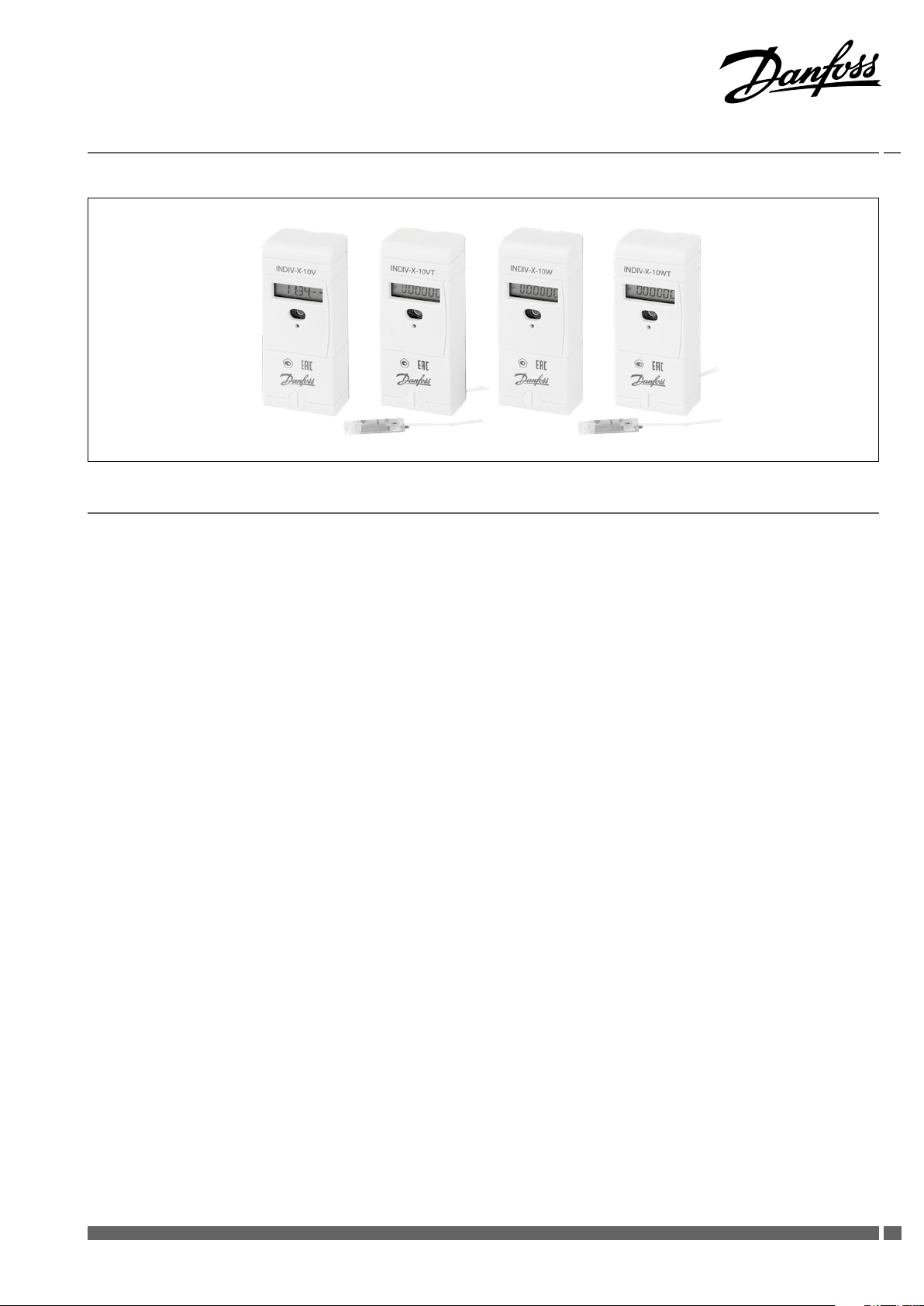
2.1.6 Versions
• Heat cost allocator INDIV-X-10V with optical interface, standard
device
• Heat cost allocator INDIV-X-10VT with optical interface, remote
sensor device with 1.5 m cable
::
Display with all active segments
• Radio heat cost allocator INDIV-X-10W with optical interface,
standard device
• Radio heat cost allocator INDIV-X-10WT with optical interface,
remote sensor device with 1.5 m cable.
2.1.7 Optical Interface
With a standardised optical probe the consumption and
configuration values can be transferred directly to a computer.
With the radio heat cost allocator INDIV-X-10W all consumption
values can thus be readout over the optical interface and over
radio. The data are transmitted in M-bus-format acc. to EN1434.
Authorised personnel can alter the configuration of the device
over the optical interface with an optical probe.
2.1.8 Radio Transmission
The radio heat cost allocator INDIV-X-10W features a transceiver
circuit in the 433 MHz band with integrated antenna. With the
radio system, proven since more than 10 years; it is possible to
readout the consumption values via a mobile radio modem or via
a radio central installed directly in the office. The radio system is a
bidirectional system, i.e. the radio heat cost allocator is only called
from a mobile PDA or a radio central upon request to send its data.
It is a great advantage that this system allows the alteration of the
parameters over radio.
Danfoss Heating VIIGC102
55
Page 6
Installation Guide Electronic Heat Cost Allocator INDIV-X-10V, INDIV-X-10W Radio
2. Specification
2.2 Operating mode
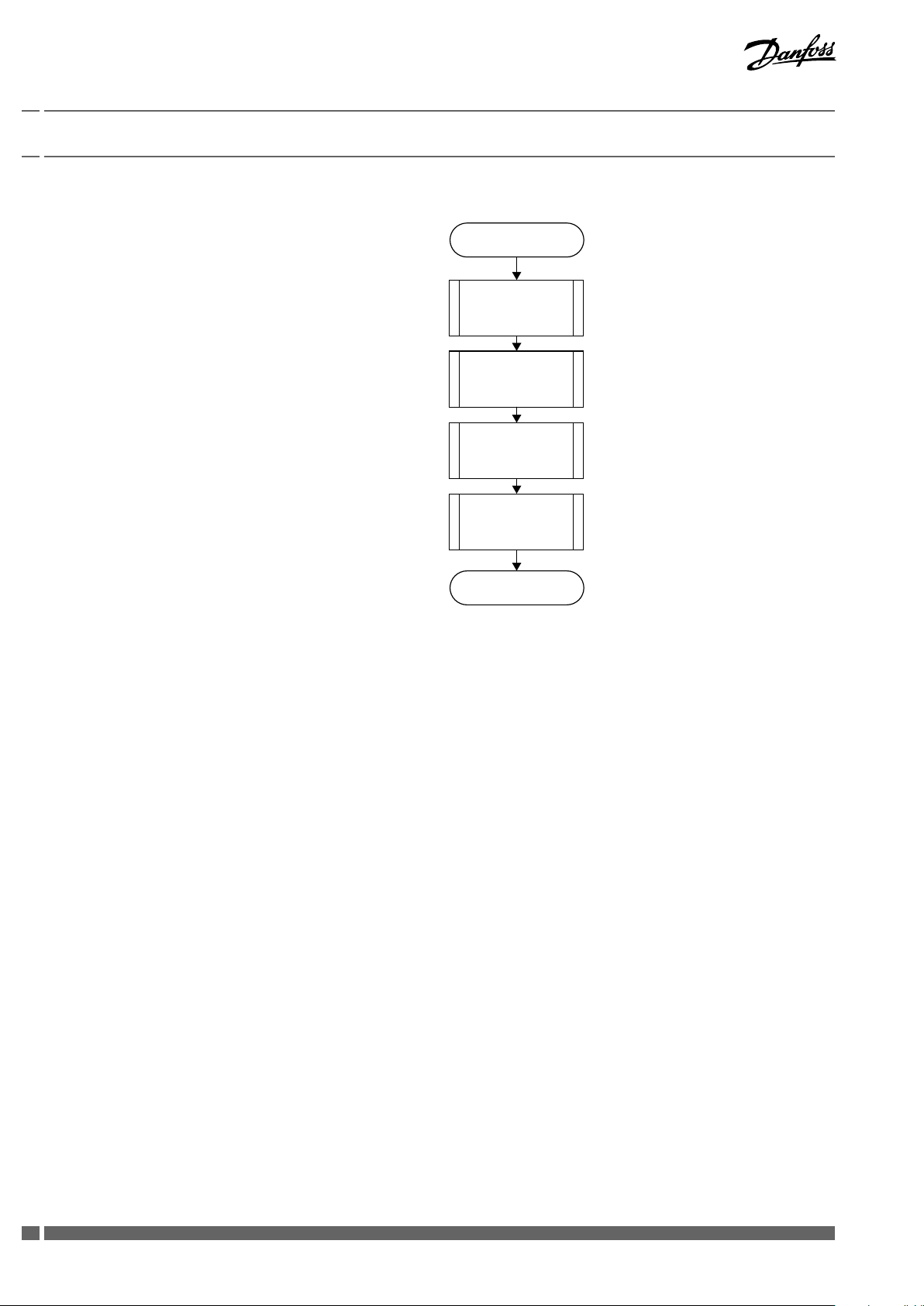
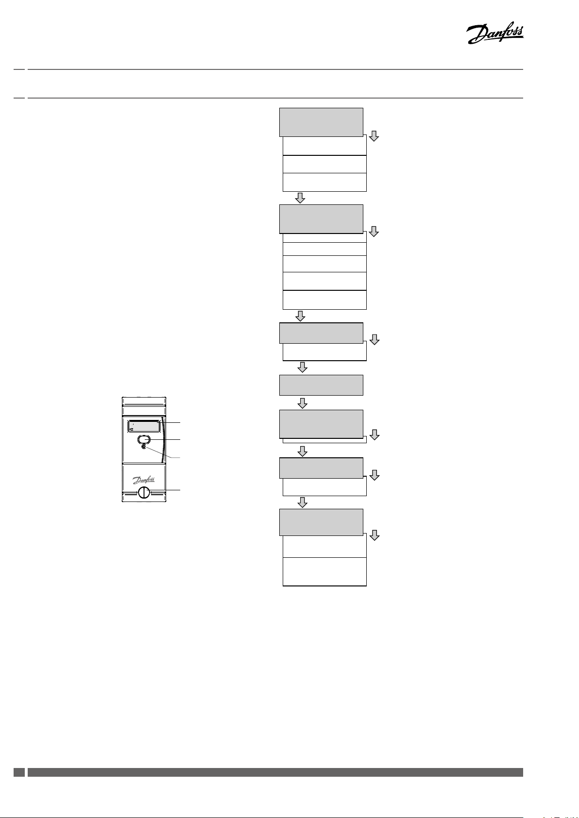
2.2.1 Cycle Time
The heat cost allocators INDIV-X-10V / INDIV-X-10W operate in
a cycle of 4 minutes. Most of the time, the device is in sleeping
mode. Every 4 minutes the device is set into operation and
operates according to the adjoining diagram.
The clock-pulse generator is a counter which is completely
independent from the rest of the programme. This counter is
designed in a way so that it is impossible to stall the cycle or to
skip one or more cycles.
Each cycle follows the adjoining diagram. The measuring and
calculating processes are explained in detail later.
The tasks carried out during one cycle are taking approx. 200 ms.
This means that the device is in sleeping mode more than 99.8 %
of the time. It can be set into operation between two cycles over
the optical probe or by pushing the button. In this case it carries
out the requested task and then returns to sleeping mode.
In case an optical probe is connected or the button is pushed
during the course of the cycle, the respective value is readout at
the end of the cycle.
Start of cycle
Update time and
date
Measuring and
calculation of the
temperatur
Calculation of the
new consumtion
value
Update display
End of cycle
The button can be pushed for an indefinite period of time and the
optical probe can be left in its position since the normal function
of the device is not impaired by an influence from outside.
2.2.2 Single Sensor Version with Start Sensor
The start sensor of the single sensor version serves as an ambient
temperature sensor which mainly functions during the heating up
period.
The start temperature is the threshold temperature of the radiator
at which the device always starts to carry out energy ratings. For
these ratings, the measured radiator temperature and an assumed
ambient temperature of 20° C are used as calculation basis.
2.2.3 Double Sensor Version
For the double sensor version basically the same specifications
apply as for the single sensor ver-sion with start sensor. However,
for calculating the room temperature the real temperature,
meas-ured by the ambient temperature sensor (corrected via the
corresponding radiator-dependent „Kair-value“), is used as the
basis.
2.2.3.1 Heat Accumulation Mode
In order to avoid faulty measuring due to heat accumulation (e.g.
in case the radiator is hidden by panels), the device switches from
a defined ambient temperature (e.g. 28°C) to the one sensor mode
and calculates with an ambient temperature of 20° C.
6
VIIGC102 Danfoss Heating
Page 7

Installation Guide Electronic Heat Cost Allocator INDIV-X-10V, INDIV-X-10W Radio
2. Specification
2.2.4 Comparison of the Measuring Principles
Single sensor device with start sensor measuring principle
For heating systems with tm
≥ 55 °C
min
The heat cost allocator calculates with a set reference temperature
of 20 °C
Application:
Single sensor devices with start sensor are used in areas where
normal ambient temperatures are given. For low temperature
heating systems the double sensor device is recommended.
For radiators which are covered or blocked by fixtures, normally
the single sensor devices are used because the double sensor
device is not in a position to capture the current ambient
temperature due to the heat accumulation.
The processes for determining the K-value for the single sensor
device with start sensor and the double sensor device are
identical. It is only the measuring principle that is different.
2.2.5 Temperature Measurement and Calculation
The temperature is measured with an NTC – resistor. For the
resistance measurement the dis-charging time of the capacitor is
measured. The measurement is carried out as follows:
2.2.5.1 Measuring of a Resistor, Principle
1. Charging of the capacitor
Double sensor measuring principle
For heating systems with tm
≥ 35 °C
min
The heat cost allocator calculates with a variable reference
temperature T
air temperature
Application:
Double sensor devices are used in areas where precise measuring
of the ambient temperature is necessary and/or in low
temperature heating systems.
Radiators which are covered or blocked by fixtures are detected
automatically by the double sensor system which then switches
over internally to the single sensor mode.
Within one billing unit, only one measuring principle
(either single sensor measuring principle with start sensor
or double sensor measuring principle) can be used. Mixed
fitments or the use of different types of devices in the same
billing unit is therefore also not allowed.
2. Discharging of the capacitor through the resistance which is to
be measured. At the same time a 16-bit-timer starts with the
discharge to measure the discharging time.
3. As soon as the voltage on the capacitor terminals reaches a
certain value, an interrupt is in-duced and the timer stops. At the
same time the discharging of the capacitor is stopped as well.
After the three mentioned stages, the timer provides a 16-bitvalue which corresponds to the dis-charging time of the capacitor
through the resistance which is to be measured. In case the
resistance is known (reference resistance), the constant ratio
between discharging time and resistance can be assessed.
Danfoss Heating VIIGC102
77
Page 8
Installation Guide Electronic Heat Cost Allocator INDIV-X-10V, INDIV-X-10W Radio
2. Specification
2.2.5.2 Calculation of the Value of an Unknown Resistance
(e.g. sensor resistance)
The capacitor C is loaded at constant current. The interrupt at the
end of the discharge is triggered by the same threshold voltage (a
fraction of the discharge voltage). If these two conditions are met,
the discharge time is directly proportional to the resistance. With
a reference resistance R
possible to calculate the unknown resistance value Rx with the
following equation:
From this equation the self-calibration of the converter can
be derived, which is given by measuring the discharging time
through the reference resistance.
2.2.5.3 Measuring of the Radiator and Ambient Temperature
The following measurements are carried out during one cycle:
1. Measuring of the reference resistance R
2. Measuring of the ambient temperature sensor NTC
3. Measuring of the radiator temperature sensor NTC
whose exact value is known, it is now
ref
ref
A
R
The measuring values are calculated with the following formula:
The reference resistance value is defined ex works with a tolerance
of 0.5% with 50 ppm. The reference resistance features an excellent
temperature and long-term stability.
The capacitor value and the threshold voltage have to remain
stable over the whole cycle. However, they can vary at the
medium- or long term without causing any failures because the
self-calibration of the converter is repeated in every cycle while
measuring the reference resistance.
2.2.6 Calculation of the Displayed Consumption Value
The value displayed on the heat cost allocator is calculated as
follows:
Single sensor device Double sensor device
Explanation: TH Temperature of the radiator surface in [°C]
TA Ambient temperature in [°C]
Q Displayed consumption value, without unit
K Correction factor
Unit scale: K = 1, set, transmitted via readout telegram 0.
Product scale: Acc. to entry K = KC * KQ
! see also in chapter 6.1.2 Rating of radiators !
8
VIIGC102 Danfoss Heating
Page 9
Installation Guide Electronic Heat Cost Allocator INDIV-X-10V, INDIV-X-10W Radio
2. Specification
2.2.7 Start of Counting
The updating (increment) of the consumption value is carried out
under the following conditions:
During winter period (heating period):
(TR ≥ 25 °C)
OR
(TR ≥ 20 °C ) AND (TR - TA ≥ ΔT
MIN
)
During summer period (off heating period):
(TR ≥ 35 °C)
OR
(TR ≥ 20 °C ) AND (TR - TA ≥ ΔT
Explanation: T
TA Ambient temperature
ΔT
radiator and room
Radiator temperature
R
Minimum temperature difference between
MIN
MIN
)
3K for standard device (winter heating
period standard setting)
4K for remote sensor device (summer
heating period standard setting)
Danfoss Heating VIIGC102
99
Page 10
Installation Guide Electronic Heat Cost Allocator INDIV-X-10V, INDIV-X-10W Radio
Long key press
Long key press
Long key press
Long key press
Long key press
Long key press
Display position 7
Display position 6
Display position 5
Display position 4
Display position 2
Display position 1
Display position 3
2. Specification
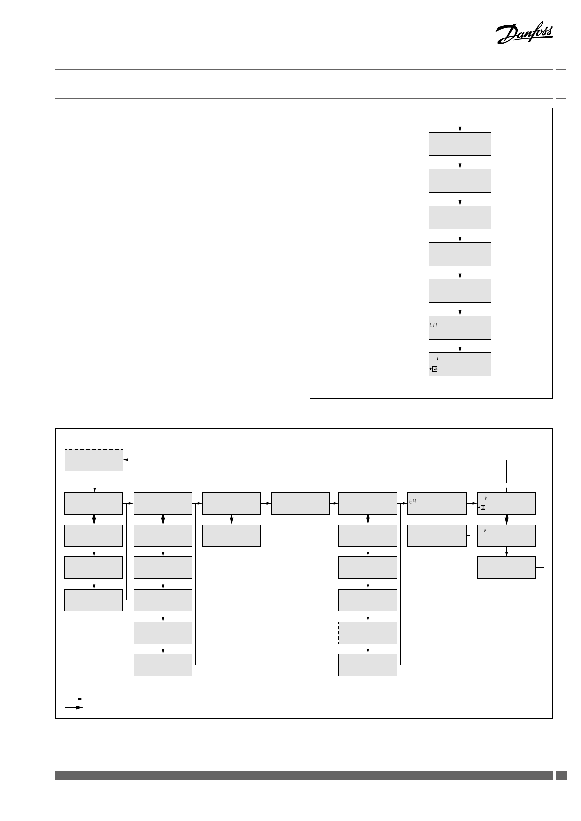
2.3 Display and Additional Functions
Comsumption value
2.3.1 The Menu Sequences of the Digital Display
The menu sequences
Ex factory all menu sequences are activated. With the software
INDIV-X-VISUAL-CONF the order of the menu sequences 1 - 7 can
be changed in any order. However the order within the individual
menu sequences 1 – 7 can-not be changed. It is also possible to
hide individual menu sequences so that they are not visible to the
end-user.
When reading out over the optical interface or via radio the
complete set of data is always readout and transferred.
Operation of the Push Button
When pushing the button briefly the digital display always goes to
the next menu sequence.
When pushing the button in one menu sequence for 2 seconds
the individual values within the selected menu sequence can
be accessed. When the last value within one menu sequence
has been displayed, the next menu sequence can be reached by
pushing the button again.
If the button is not pushed for 2 minutes, the digital display
returns to the cumulated consumption value.
::
LCD-Display
Optical
Interface
Push Button
Set day value
Check code
Value on December 31st
or before the reset to 0
Short key press
Current time
Current date
Set day date
Date of opening of the
device
Commissionen date
Cumulated duration of the
opening of the device
Short key press
Set day value
Check code
Short key press
Check code
Short key press
Monthly values
Short key press
Radiator temperature
Seal
10
VIIGC102 Danfoss Heating
Ambiant temperature
Short key press
Segment test
Identication number
Measuring principle +
software version
Page 11
Installation Guide Electronic Heat Cost Allocator INDIV-X-10V, INDIV-X-10W Radio
2. Specification
Display loops and display menu sequences – example
The display loops and display menu sequences are customized, for
example, the rolling display:
Current consumtion
unit scale
Date and Time
Set Day Value unit scale
Check code
Last monthly value
Radiator Temperature
Segment Test
::
.
::
7 S
7 S
7 S
7 S
7 S
7 S
1 S
And the display menu sequences:
Error messages
Current consumtion
unit scale
Short pression on push button (1s)
Long pression on push button (>2s)
Date and Time
::
..
..
..
..
Set Day Value unit scale Check code Monthly Value Radiator Temperature Segment Test
.
.
::
.
Danfoss Heating VIIGC102
1111
Page 12
Installation Guide Electronic Heat Cost Allocator INDIV-X-10V, INDIV-X-10W Radio
2. Specification
2.3.2 The Digital Displays
During normal operation the display is deactivated and can
be activated by pushing the button. On request, the heat cost
allocator is also available with permanent display from 06:00 –
20:00 h or 24 hours a day. The consumption value is displayed.
By pushing the button and depending on the configuration of the
heat cost allocator more than 50 different values can be displayed.
If the button is not pushed, the display will be active for 2 minutes
only. Exception: permanent display mode.
Consumption Value Unit Scale
On the display of the heat cost allocator with unit scale an index u for unit is shown on the left
side. If the index u is not displayed, the heat cost allocator is equipped with the product scale.
Consumption Value Product Scale
When commissioning the device this value is 000000. When reaching the value 999999, the
counting restarts automatically at 000000.
Set Day Value
With the index ud the consumption value in unit scale recorded at midnight of the set day is
displayed.
Set day Value product scale
Check Code
Consumption Value of the
Previous Heating Period
Time
If a new device has not yet reached the programmed set day, 000000 is displayed.
With the index d the consumption value in product scale recorded at midnight of the set day is
displayed.
If a new device has not yet reached the programmed set day, 000000 is displayed.
With the index cc the check code for the plausibility check of the manual readout is displayed.
With the index uI the consumption value is displayed which was recorded on December 31st or
before the reset to zero.
000000 is displayed on a new device as long as a reset has not been carried out.
The current time (always winter time)
:
12
VIIGC102 Danfoss Heating
Page 13
Installation Guide Electronic Heat Cost Allocator INDIV-X-10V, INDIV-X-10W Radio
2. Specification
Date
The current date of the heat cost allocator
..
Set Day
..
Date of Opening of the Device
..
Commissioning Date
It is possible to program an annual set day on which the cumulated consumption value as well
as the maximal radiator temperature are recorded.
With the index Sd the programmed annual set day is displayed.
Each heat cost allocator is equipped with a manipulation protection which detects an
unauthorised opening of the device after installation to the radiator. The date of the opening of
the device is recorded and displayed with the index od.
With the index cd the commissioning date is displayed, i.e. the date on which the device has
been activated by pushing the button or the date of commissioning programmed ex factory.
..
Cumulated Duration of the
Opening of the Device
Identification Number
Monthly Values
Values
The cumulated duration in minutes during which the device was opened is detected. This
display turns up only after commissioning in case the heat cost allocator was opened or
removed.
With the index
identical with the identification number. The first two digits of the identification number are
the two small digits on the left upper side of the digital display.
The cumulated consumption values are recorded automatically at midnight on the last day of
each month.
Number of monthly values: 18 or 36
The small digits on the upper left side show the number of previous monthly values. Digit 01
stands for the recent full month and digit 18 or 36 stands for the least recent month.
All monthly values are set to 000000 when the device is commissioned.
an 8 digit identification number is displayed. Ex factory the serial number is
Note INDIV-X-10W radio:
The radio heat cost allocator INDIV-X-10W only transmits the first 16 monthly values
via radio telegram.
Danfoss Heating VIIGC102
1313
Page 14
Installation Guide Electronic Heat Cost Allocator INDIV-X-10V, INDIV-X-10W Radio
2. Specification
Half Monthly Values
Radiator Temperature
The cumulated consumption values are recorded automatically at midnight on the 16th of
each month.
The small digits on the upper left side indicate the number of half monthly values. Digit 41
stands for the recent half monthly value and digit 58 for the least recent half monthly value. All
half monthly values are set to 000000 when the device is commissioned.
If the heat cost allocator INDIV-X-10V is programmed with 36 monthly values the menu
sequences for the half monthly values are omitted.
Note INDIV-X-10W radio:
The heat cost allocator INDIV-X-10W does not transmit the half monthly values via
radio telegram.
With the index tH the current radiator temperature is displayed.
.
Ambient Temperature
With the index tA the current ambient temperature is displayed.
.
Maximum Radiator Temperature
of the Current Heating Period
With the index P0 the maximum radiator temperature since the last reset or of the current
heating period is displayed.
.
Maximum Radiator Temperature
of the Previous Heating Period
With the index P1 the maximum radiator temperature before the last reset or of the previous
heating period is displayed.
.
Measuring Principle and
Software Version
.
Segment Test
With the index F1 or F2 the measuring principle is displayed.
F1 = single sensor device with start sensor
F2 = double sensor device
On the right side the software version x.xx of the heat cost allocator is displayed.
Segment test of the display.
::
Error Message
If an error is detected, Err is displayed in the first display sequence with the corresponding error
message.
14
VIIGC102 Danfoss Heating
Page 15

Installation Guide Electronic Heat Cost Allocator INDIV-X-10V, INDIV-X-10W Radio
2. Specification
2.3.3 Rolling Digital Display
The EHCA INDIV-X-10V and INDIV-X-10W also feature the
possibility of a rolling display between 06:00 – 20:00 h.
With the software INDIV-X-VISUAL-CONF it is possible to
individualise the rolling display. Up to 7 parameters can be chosen
optionally from the list below. These parameters can be combined
in any order and are then shown on the rolling display.
• Consumption value
• Time
• Date
• Set day
• Set day value
• Last monthly value
• Last half monthly value
• Radiator temperature
• Ambient temperature
• Maximum radiator temperature of the current heating period or
since the last reset
• Segment test
The duration of the display of the values can be chosen
individually as follows:
• Short duration: 1 s (set, cannot be changed)
• Long duration: 2 - 7 s (only one value can be chosen)
Example:
Order and duration of display
• Pos. 0: Error (parameter ex factory, cannot be changed [5 s]
(only displayed in case of an error message)
• Pos 1: Time [1 s]
• Pos 2: Segment test [1 s ]
• Pos 3: Consumption value [4 s]
• Pos 4: Set day [1 s]
• Pos 5: Set day value [4 s]
• Pos 6: Last monthly value [1 s]
• Pos 7: Blank (therefore no display. It is not necessary to
occupy all positions)
The rolling display can also be deactivated by the
INDIV-X-VISUAL-CONF, i.e. the device operates as in standard
menu mode except that only these values and the values of the
corresponding sub-menus that have been defined in the rolling
menu can be displayed by pushing the button. After 2 minutes
during which the button has not been pushed, the display goes
out.
Danfoss Heating VIIGC102
1515
Page 16
Installation Guide Electronic Heat Cost Allocator INDIV-X-10V, INDIV-X-10W Radio
2. Specification
2.3.4 Energy-Saving Night Mode between 20.00 and 6.00 h
If the LCD-display is activated, the heat cost allocator switches
automatically to the energy-saving night mode between 20.00
and 06.00 h (winter time). During this period the LCD-display is
deac-tivated and switched off generally.
2.3.5 Communication Indicator
The communication indicator displays if the heat cost allocator is
currently making a calculation and/or if it communicates internally
or externally over the optical or wireless interface.
2.3.6 Real Time Clock and Calendar
The device has a 24 h real time clock and a calendar. However, the
change from summer to winter time is not taken into account. The
calendar is programmed until December 31 2099, including all
leap years. The real time clock as well as the date of the heat cost
allocator can be readout over the optical interface or via radio and
if necessary be updated.
If the arrow of the communication indicator points inwardly internal communication takes
place over the optical or wireless interface.
If the arrow of the communication indicator points outwards external communication takes
place over the optical or wireless interface.
If the frame of the communication indicator appears the heat cost allocator is carrying out a
measuring or a calculation.
If the current date and time have to be updated over the
optical interface or via radio, it is necessary to check the
date of the computer first. Date and time of the device
aim at those of the computer. If the reading/programming
device (computer/PDA/ Smart Phone) has a wrong time, this
time will be programmed into the heat cost allocator and
suddenly no longer be reached at the usual time, because
the time of the heat cost allocator possibly is shifted by
several hours.
16
VIIGC102 Danfoss Heating
Page 17

Installation Guide Electronic Heat Cost Allocator INDIV-X-10V, INDIV-X-10W Radio
2. Specification
2.3.7 Readout
The current and monthly values recorded by the heat cost
allocator INDIV-X-10V and INDIV-X-10W as well as several other
parameters can be readout over the optical interface or also over
radio with the heat cost allocator INDIV-X-10W (see description
chapter 5).
The following parameters are transmitted:
• Identification number (information in header)
• Error
• Software version
• Date and time
• Consumption value
• K
-value x KQ-value
c
• Current radiator temperature
• Current ambient temperature
• Date of the opening of the housing
• Cumulated duration of the opening of the housing in minutes
• Date of commissioning
• Set day
• Set day value
• Value of previous heating period
• Maximum radiator temperature of current heating period
• Maximum radiator temperature of previous heating period
• Monthly values
• Half monthly values
• Serial number
2.3.8 Check Code
A special additional feature of the electronic heat cost allocator
INDIV-X-10V is the check code function for the postcard mail-in
method.
With especially developed algorithms a 6 digit check code is
generated out of several device data. With this check code the
values stated on the postcards mailed-in by tenants can be cross
checked.
For this check
• the date
• the current consumption value
• the set day value and
• the check code
are required.
For the verification of the check code Danfoss places all necessary
tools (programmes, formulas) at the disposal of the authorised
personnel.
Danfoss Heating VIIGC102
1717
Page 18

Installation Guide Electronic Heat Cost Allocator INDIV-X-10V, INDIV-X-10W Radio
2. Specification
2.3.9 Change of Battery
The battery of the heat cost allocator is soldered. The lithium
battery is not rechargeable. A change of battery is not planned.
Therefore the heat cost allocators have to be replaced after 10
years.
Disposal
It is mandatory to dispose of the heat cost allocator
environmentally friendly or to return it after use to the
manufacturer for appropriate disposal to ensure that the
components are recycled in accordance with the battery and
electronic scrap regulations. Should you do the disposal yourself
please get information from your local authority on the recycling
possibilities.
2.3.10 Protection against Outside Influences
2.3.10.1 Seal and seal sticker
The heat cost allocator is closed with a seal which cannot be
removed without damaging it. Thus it is impossible to open the
device unnoticed.
A seal sticker as second seal is used for further protecting against
manipulation. After mounting, the seal sticker is fixed between
housing of heat cost allocator and aluminium back plate. Heat cost
allocator cannot be removed from aluminium back plate without
damaging a sticker.
After installation, the electronic part of the device is no longer
accessible. The digital display, the push button and the optical
interface are covered by a sight glass. It is impossible to access the
inside of the device through these openings without damaging
the sight glass.
2.3.10.2 Electronic Detector in Case of an Opening of the Device
The electronic detector detects unauthorised opening, removing
and closing of the heat cost allocator. As soon as the housing of
the heat cost allocator is opened and/or removed, the electronic
detector triggers an error message. The duration of each opening
is counted, cumulated and only the last date of opening recorded.
18
VIIGC102 Danfoss Heating
Page 19

Installation Guide Electronic Heat Cost Allocator INDIV-X-10V, INDIV-X-10W Radio
2. Specification
2.4 Special Functions
2.4.1 Suppression of Summer Counting
The period during which summer counting is suppressed can be
programmed by the software.
If the heat cost allocator is in the period of summer counting
suppression, consumption measuring is deactivated. If an
automatic readout is carried out during this period the
temperatures can be read anyway since the temperature
measuring is still active.
2.4.2 Programmable Start Temperature of Summer and
Winter period
The threshold values for the start temperature can be
programmed separately for the summer and winter period within
a temperature range of 25 - 40 °C in steps of 0.01°C. The respective
change-over days (e.g. summer period as from May 15th and
winter period as from October 15th) are also freely programmable.
By separating the start temperature for the summer and winter
period, it is possible to avoid a faulty energy rating due to sun
exposure. If the value is below the start temper-ature, an energy
calculation is carried out in accordance with the conditions
mentioned in chapter 2.2.7.
2.4.3 Annual Reset of the Values
The function of the annual reset of the cumulated consumption
value can be programmed by the software over the optical
interface. One of the following dates can be chosen for the reset:
• December 31st
• Set day
• Start summer period
• Start winter period
If the special function „suppression of summer counting“
is activated, the homologation acc. to EN 834 is void. This
special function is not included in the applicable standard.
Please note that only the cumulated consumption value is reset.
All other values are not reset.
2.4.4 Unit Scale and Product Scale
For the heat cost allocators INDIV-X-10V and INDIV-X-10W,
distinction is made between the unit scale and the product scale.
If heat cost allocators are used with the same scale on all radiators,
this scale is called unit scale. The display values are the same on
the different radiators if the heat cost allocators are exposed to the
same temperature for the same period of time.
The evaluation of the display values is carried out arithmetically
with the rating factors of the calculation software to receive the
final consumption values.
Danfoss Heating VIIGC102
1919
Page 20

Installation Guide Electronic Heat Cost Allocator INDIV-X-10V, INDIV-X-10W Radio
2. Specification
2.4.4.1 Advantages of the Unit Scale
• Easy and quick installation of the heat cost allocator, no
programming necessary
• Possible errors by doing the scaling on site are avoided due to
allocation by experts.
With the product scale, the radiator rating data are programmed
in the heat cost allocator on site. The overall rating factor K
is calculated directly in the heat cost allocator and thus the
consump-tion value is displayed immediately.
2.4.4.2 Advantages of the Product Scale
• The actual consumption of each consuming point within one
billing unit can be compared easi-ly and quickly on site.
total
20
VIIGC102 Danfoss Heating
Page 21

Installation Guide Electronic Heat Cost Allocator INDIV-X-10V, INDIV-X-10W Radio
2. Specification
2.5 Parameterisation
With the software INDIV-X-VISUAL-CONF the following
parameterisations can be carried out over the optical interface:
Parameterisation ex factory - Example
Date and time UTC+1 (winter time)
Set day 01.01.
Date of commissioning deactivated
Start of summer period May15
End of summer period October 15
Start temperature summer period 35°C (Radiator temperature)
Start temperature winter period 25°C (Radiator temperature)
Activation of heat accumulation mode summer period 35°C (Maximum ambient temperature)
Activation of heat accumulation mode winter period 28°C (Maximum ambient temperature)
Double sensor measuring principle activated
Single sensor measuring principle with start sensor deactivated
Reset to zero of consumption value deactivated
Suppression of summer counting deactivated
Unit scale activated §
Product scale deactivated
Rating factor KC 1.0 §
Rating factor KQ 1.0 §
36 monthly values activated
18 monthly and 18 half monthly values deactivated
Check code activated
Identification number identical with serial number
Digital display deactivated
Menu sequences all
Rolling display activated
Sleeping mode activated
Cold counting deactivated
§ Unit scale ➞ K
With the software INDIV-X-VISUAL-CONF it is also possible to reset all recorded consumption values as well as all error
messages. Furthermore, the device can also be reprogrammed from operation to sleeping mode.
= KQ = 1.0 displayed in the telegramme as KC * KQ = 1.0
C
2.6 Error
2.6.1 Description of the Function Control
After a hardware reset and before each measuring the
microcontroller carries out a self-test. In case an error is detected,
the corresponding error-bit in the RAM is set and the respective
error message is displayed on the digital display. After 4 minutes a
reset is carried out (before the next measuring) and the recorded
error-bit in the RAM is deleted automatically. If after the reset the
error is detected again, the corresponding error-bit in the RAM
is also set and the respective error message is displayed on the
digital display.
Danfoss Heating VIIGC102
2121
Page 22

Installation Guide Electronic Heat Cost Allocator INDIV-X-10V, INDIV-X-10W Radio
2. Specification
2.6.2 List of Errors
Err.001 Manipulation (fraud) ! Disabled with remote sensor
version !
Err.002 Measuring error
Err.008 Only INDIV-X-10W: error EEPROM, error of radio
communication
Err.016 Error of digital display – the data to be processed cannot
be displayed
Err.032 Button pushed constantly
Err.064 Measured temperature not within temperature range
(0..105°C; 0..120°C remote sensor). Cable of remote
temperature sensor are in contact (short-circuited).
Err.066 Cable of remote temperature sensor are not in contact.
2.7 Radio Standby – Radio-HCA INDIV-X-10W
In order to achieve a user-friendly and power-saving radio standby,
the radio heat cost allocator features the following different
operating modes:
2.7.1 Sleeping Mode
Ex factory the radio heat cost allocator INDIV-X-10W is in sleeping
mode, but the internal clock and the date are running.
Current consumption is reduced to a minimum since no
measuring and no calculations are carried out and furthermore
communication options are not assisted.
Transition from sleeping to installation mode is achieved by
pushing the button once or by reaching the programmed
commissioning date.
2.7.2 Installation Mode
During the installation mode all functions of the radio heat cost
allocator are carried out and radio transmission is possible for max.
24 hours. This guarantees an optimal availability of the radio heat
cost allocator for test purposes during installation.
The radio heat cost allocator remains in installation mode until
midnight and then switches over automatically to operation
mode.
midnight
Sleeping mode Installation mode Operation mode
Transition from sleeping mode to installation mode is
achieved by pushing the button once or by reaching the
programmed commissioning date
22
VIIGC102 Danfoss Heating
Page 23

Installation Guide Electronic Heat Cost Allocator INDIV-X-10V, INDIV-X-10W Radio
2. Specification
2.7.3 Operation Mode
2.7.3.1 Walk-By Radio Remote Readout
A walk-by remote readout of the data of the heat cost allocator
INDIV-X-10W is possible every day from 6.00 to 17.58 (winter time).
No readout possible between 18.00 and 20.00 (winter time)!
2.7.3.2 Readout over Radio Central (installed directly in
the building)
For the readout over a radio central installed in the building, the
following applies (see table below):
The device with the corresponding final numeral of the serial
number is ready for radio transmission during the time stated in
the table below.
Time Serial Number
20:00 – 20:58 XXXXXXX0
21:00 – 21:58 XXXXXXX1
22:00 – 22:58 XXXXXXX2
23:00 – 23:58 XXXXXXX3
00:00 – 00:58 XXXXXXX4
01:00 – 01:58 XXXXXXX5
02:00 – 02:58 XXXXXXX6
03:00 – 03:58 XXXXXXX7
04:00 – 04:58 XXXXXXX8
05:00 – 05:58 XXXXXXX9
After readout of the data from the radio heat cost allocator, the
radio availability is deactivated again.
Danfoss Heating VIIGC102
2323
Page 24

Installation Guide Electronic Heat Cost Allocator INDIV-X-10V, INDIV-X-10W Radio
3. Installation
3.1 Introduction
To guarantee the proper functioning of the heat cost allocator
INDIV-X-10V and INDIV-X-10W, it is of great importance that it
is installed by an expert. On one hand, a constant heat transfer
between radiator and heat cost allocator has to be guaranteed.
On the other hand, the installation of the heat cost allocators to a
large variety of radiator types should be as easy as possible.
The installation can be carried out in two different ways. The
standard device is installed directly to the radiator. For the
wall-mounted version the remote sensor is installed to the radiator
and the heat cost allocator is wall-mounted. For the installation of
the heat cost allocators, special fastening-parts kits are available.
To avoid faulty installation, we also recommend reading the Kcdata in the data base prior to the installation.
The heat cost allocator is an electronic device which – like all
other similar devices – has to be handled with care. It is sensible to
electric discharge and contacting certain areas of the PCB. Electric
discharge can destroy the device or – even worse - damage it in a
way that it fails after an indefinite period of time.
For this reason it is essential to avoid contact with the PCB.
3.2 DIN Standard Requirements for the Installation
a. Heat cost allocators can be installed in heating systems where
the mean design heating medium temperature is between
the upper operating temperature limit tmax and the lower
operating temperature limit t
technical data, see enclosure)
b. The installation of the devices has to be durable and safe against
manipulation.
c. The devices have to be installed in a place where sufficient
correlation between the displayed value and the heat output of
the radiator is given over a maximum operating range.
d. Within one billing unit (in case of pre-distribution of the energy
consumption: within one users’ group) only heat cost allocators
of the same make and the same type with identical rating
systems may be used. Each device type has to be identifiable as
such.
e. Combinations of radiators and heat cost allocators with a
measured value of c > 0.3 in basic condition are not permitted.
In exceptional cases c-values of up to 0.4 are permitted within
one billing unit if the concerned heating surface does not
exceed 25 % of the overall heated surface or if the mean design
heating medium temperature is above 80°C. Heat cost allocators
may only be installed to radiators where the c-value is known at
the time of billing.
min
(t
and t
max
are stated in the
min
24
VIIGC102 Danfoss Heating
Page 25

Installation Guide Electronic Heat Cost Allocator INDIV-X-10V, INDIV-X-10W Radio
3. Installation
3.3 General Restrictions
Electronic heat cost allocators cannot be used with steam heating,
floor heating, ceiling radiant heaters and flap-controlled radiators.
In case of combined valve- and flap-controlled radiators, the
installation of an electronic heat cost allocator is only permitted if
the flap control is dismounted or shut down in position „open“.
Convector heaters where the performance can be altered by an
electric blower as well as heat towel racks with an electric heating
cartridge may only be equipped with an electronic heat cost
allocator if the additional electric attachments are dismounted or
shut down.
3.4 Operating Range
The heat cost allocators can be used in heating systems with the
following mean heating medium temperatures:
For single sensor devices with start sensor
55°C…105° C for standard heat cost allocator
55°C…120°C for wall-mounted heat cost allocator (remote sensor)
For double sensor devices
35°C…105° C for standard heat cost allocators
55°C…120°C for wall-mounted heat cost allocators (remote
sensor)
A heat cost allocator can be used in heating systems where the
suitability of the system is in line with the operating conditions for
which the heat cost allocator has been approved.
The diagram in the enclosure 1 should be used to check if the
heating system is in line with the operating range.
Please refer to standard EN 834 (excerpt in enclosure 3) for the
definition of the terms.
Danfoss Heating VIIGC102
2525
Page 26

Installation Guide Electronic Heat Cost Allocator INDIV-X-10V, INDIV-X-10W Radio
0,75 x BH
3. Installation
3.5 Installation to the Radiator
The heat cost allocator is always installed in the middle of the
overall length (0,5 x BL) of the radiator at a height of ¾ of the
overall height (0,75 x BH) measured from the bottom to the small
round whole in the middle.
If the height of the radiator is less than (<) 470 mm, the heat
cost allocator must be installed at 50% BH.
If the radiator has an even number of sections the heat cost
allocator is installed between the middle sections. If the radiator
has an uneven number of sections the device is installed next to
the valve-sided middle section.
When welding the heat cost allocator the upper threaded bolt has
to be welded from the bottom side in the middle of the overall
length (0,5 x BL) and at a height of (0,75 x BH) + 2 cm. The lower
bolt is positioned vertically 5 cm below the upper bolt and welded.
Before welding the lacquer has to be removed from the welding
points. Atten-tion has to be paid that the bolts are welded onto a
water-bearing area or a flute. Only use M3 bolts with a maximum
length of 8 mm or there’s a risk that the device will be damaged.
Mount the back plate through the 2 oval holes, adjusted to the top
edge of the 2 ovals holes.
0,5 x BL
0,5 x BL
0,75 x BH
If the radiator is of a length of more than 3 m, two heat cost
allocators have to be installed. This radiator is thus regarded as
two series connected individual radiators which however are
individually.
Example of 2 heat cost allocators
Mounting: 0.75 X BH + 2 cm to the upper bolt
5 cm
(0,75xBH)+2 cm
0,5 x BL
0,5 x BL
0,25 BL
0,25 BL
26
VIIGC102 Danfoss Heating
0,75 BL
Page 27

Installation Guide Electronic Heat Cost Allocator INDIV-X-10V, INDIV-X-10W Radio
3. Installation
3.6 Wall-Mounting
The heat cost allocator has to be wall-mounted if the overall
height of the radiator is less than 250 mm or if, for aesthetical
reasons, the heat cost allocator cannot be mounted directly onto
the radiator.
In this case, the heat cost allocator is wall-mounted on the side
opposite to the valve and at a minimum distance from the radiator
of 10 cm.
at least
10 cm
at least
10 cm
• After marking and drilling the holes, the aluminium profile is
fastened with 2 metal screws and 2 spring washer.
• The parts necessary for the wall-mounting are included in the
corresponding fastening-parts kits for the installation of the
remote sensor.
• After installation of the device to the wall and the sensor to the
radiator, the sensor cable is laid in a cable duct.
• Mount the back plate through the 2 oval holes adjusted to the
top edge of the 2 oval holes.
088H2424
088H2345
088H2420
088H2423
Mounting Accessories Code No.
2 plastic dowels Ø5 mm 3.25 088H2424
1 aluminium back plate (supplied with EHCA) 088H2345
2 spring washers 088H2420
2 oval head wood screws 3 x 35 088H2423
Danfoss Heating VIIGC102
2727
Page 28

Installation Guide Electronic Heat Cost Allocator INDIV-X-10V, INDIV-X-10W Radio
3. Installation
3.7 Installation of Fastening-Parts Kits
3.7.1 Installation to Sectional Radiator
088H2408
088H2345
088H2420
• For radiators made from cast iron it is necessary to apply heat
transfer compound (Electrolu-be HTS) onto the contact
surfaces of the aluminium profile before installation. Mount the
back plate through the little hole in the middle.
088H2412
Mounting Accessories Code No.
1 tensioning bracket 088H2408
1 aluminium back plate (supplied with EHCA) 088H2345
1 cylinder head screw M4 x 40 088H2412
1 spring washer B 4 088H2420
3.7.2 Wall-Mounting - Sectional Radiator
• The remote sensor has to be fixed in the receiver
housing with adhesive to avoid loosening.
• The contact surfaces of the cover angles have to be
coated with adhesive before bringing them together.
• After mounting, it possible to fix a seal sticker on the receiver
housing.
0088H2408
Remote
sensor
088H2410
088H2420
088H2412
088H2406
Mounting Accessories Code No.
1 tensioning bracket 088H2408
1 aluminium profile „receiver housing“ 088H2410
1 spring washer B 4, DIN 128 088H2420
1 cylinder head screw M4 x 40 (with crosshead) 088H2412
2 cover angles, white 088H2406
2 plastic dowels Ø5 mm 3.25 (wall) 088H2424
2 oval head wood screws 3 x 35 (wall) 088H2423
28
VIIGC102 Danfoss Heating
Page 29

Installation Guide Electronic Heat Cost Allocator INDIV-X-10V, INDIV-X-10W Radio
3. Installation
3.7.3 Installation to Folded Radiator
088H2413
088H2421
088H2345
088H2420
088H2411
• Mount the aluminium back plate
through the small round hole
Mounting Accessories Code No.
1 hexagon nut B M4, DIN 934 088H2413
2 bracing angles 088H2421
2 spring washers B4, DIN 128 088H2420
1 oval head screw M4 x 30 088H2411
1 aluminium back plate (supplied with EHCA) 088H2345
• If necessary use 2 x 2 bracing angles to improve more stability
(photo) and, if needed, short the screw
Mounting Accessories Code No.
2 hexagon nut B M4, DIN 934 088H2413
2 x 2 bracing angles 088H2421
4 spring washers B4, DIN 128 088H2420
2 oval head screw M4 x 30 088H2411
1 aluminium back plate (supplied with EHCA) 088H2345
Danfoss Heating VIIGC102
2929
Page 30

Installation Guide Electronic Heat Cost Allocator INDIV-X-10V, INDIV-X-10W Radio
3. Installation
3.7.4 Wall-Mounting – Folded Radiator
088H2415
088H2414
088H2409
088H2405
088H2407
• The remote sensor has to be fixed in the
receiver housing with adhesive to avoid loosening.
• The contact surfaces of the cover angles have to be coated with
adhesive before bringing them together.
• After mounting, it possible to fix a seal sticker on the receiver
housing.
Mounting Accessories Code No.
1 tensioning nut 088H2415
1 tensioning bolt 088H2414
1 aluminium profile « receiver housing» 088H2409
1 safety plate 088H2405
2 cover angles, white 088H2407
2 plastic dowels Ø5 mm 3.25 (wall) 088H2424
2 oval head wood screws 3 x 35 (wall) 088H2423
30
VIIGC102 Danfoss Heating
Page 31

Installation Guide Electronic Heat Cost Allocator INDIV-X-10V, INDIV-X-10W Radio
3. Installation
3.7.5 Installation to Panel-Type Radiator
088H2422
088H2345
088H2418
088H2416
• Mount the back plate through
the 2 oval holes adjusted to the top edge of the 2 oval holes
Mounting Accessories Code No.
2 threaded bolts M3 x 8 (see page 27!) 088H2422
2 spring washers B3, DIN 137 088H2418
2 slotted nuts M3, DIN 546 088H2416
1 aluminium back plate (supplied with EHCA) 088H2345
Tool: Screw driver size 5 for M3
or
Mounting Accessories Code No.
2 threaded bolts M3 x 8 (see page 27!) 088H2422
2 Nuts M3 6-kant size 5.5 with flange
1 aluminium back plate (supplied with EHCA) 088H2345
Tool: Socket wrench hexagonal size 5.5
or
Mounting Accessories Code No.
2 threaded bolts M3 x 8 (see page 27!) 088H2422
2 Nuts M3 mit 6-kant size 5.5
1 aluminium back plate (supplied with EHCA) 088H2345
Tool: Socket wrench hexagonal size 5.5
Danfoss Heating VIIGC102
3131
Page 32

Installation Guide Electronic Heat Cost Allocator INDIV-X-10V, INDIV-X-10W Radio
20 mm
¼ BH**
or
½ BH**
088H2422
088H2417
Remote
sensor
088H2404
Remain inside sensor
Detached part
3. Installation
3.7.6 Wall-Mounting - Panel-Type Radiator
088H2422
20 mm
Remote
sensor
¼ BH**
or
½ BH**
088H2417
088H2404
Remain inside sensor
Detached part
• The remote sensor has to be coated with heat transfer
compound (Electrolube HTS) on the contact surface.
• Turn on the pull-off nuts 088H2417 till it breaks. After put on the
HK-sensor cover to ensure the manipulation protection.
• Mount the back plate through the 2 oval holes adjusted to the
top edge of the 2 oval holes
Mounting Accessories Code No.
2 threaded bolts M3 x 8 088H2422
2 pull-off nuts M3 088H2417
1 HK-sensor cover 088H2404
2 plastic dowels Ø5 mm 3.25 (wall) 088H2424
2 oval head wood screws 3 x 35 (wall) 088H2423
088H2424
088H2345
088H2420
088H2423
32
VIIGC102 Danfoss Heating
Page 33

Installation Guide Electronic Heat Cost Allocator INDIV-X-10V, INDIV-X-10W Radio
3. Installation
3.7.7 Installation to Panel-Type Radiator with Front
Convection Plate
088H2425
088H2419
• The contact surfaces of the aluminium screws have to be coated
with heat transfer compound (Electrolube HTS).
• The aluminium screws have to be fastened with adhesive to
avoid loosening.
Mounting Accessories Code No.
3 sheet-metal screws 2.9 x 9.5 088H2419
1 aluminium back plate 088H2425
Danfoss Heating VIIGC102
3333
Page 34

Installation Guide Electronic Heat Cost Allocator INDIV-X-10V, INDIV-X-10W Radio
3. Installation
3.7.8 Bathroom radiator – Towel rails
Heat cost allocator mounted verticaly on distributor or
collector part
• Assembly with 2 threaded bolts welded on 75% BH +50mm on
the side or front of the flow distributor or return collector
Mounting Accessories Code No.
2 threaded bolts M3 x 8 (see page 27!) 088H2422
2 spring washers B3, DIN 137 088H2418
2 slotted nuts M3, DIN 546 088H2416
1 aluminium back plate (supplied with EHCA) 088H2345
Tool: Screw driver size 5 for M3
Heat cost allocator mounted horizontally on cross tubes
• Assembly to the nearest possible place to
the flow place or return place on the cross tubes
on 75% BH with 2 tensioning brackets
Mounting Accessories Code No.
2 tensioning bracket 088H2408
1 aluminium back plate (supplied with EHCA) 088H2345
2 cylinder head screw M4 x 40 088H2412
2 spring washer B 4 088H2420
34
VIIGC102 Danfoss Heating
Page 35

Installation Guide Electronic Heat Cost Allocator INDIV-X-10V, INDIV-X-10W Radio
3. Installation
3.7.9 Sectional radiator wide
088H2428
088H2430
088H2427
088H2345
• Mount the back plate through the 2 oval
holes adjusted to the top edge of the
2 oval holes
Mounting Accessories Code No.
2 tensioning bracket 50mm 088H2428
1 aluminium back plate (supplied with EHCA) 088H2345
1 heat conductor aluminium plate 60mm 088H2427
2 cylinder head screw M4 x 40 088H2412
1 cylinder head screw M3 x 10 088H2429
1 Nut M3 088H2430
088H2412
088H2429
Danfoss Heating VIIGC102
3535
Page 36

Installation Guide Electronic Heat Cost Allocator INDIV-X-10V, INDIV-X-10W Radio
3. Installation
3.8 Overview mounting accessories
Code No. Designation
088H2400 Replacement seal 1000 pieces
088H2345 Aluminium back plate
088H2401 Plastic blind cover
088H2402 Optical head USB
088H2403 Bracket for Opto-probe
088H2404 Cover for sensor
088H2405 Safety plate
088H2406 Cover angles, white , Sectional radiator
088H2407 Cover angles, white , Folded radiator
088H2408 Tensioning bracket
088H2409 Aluminium profile « receiver housing»
088H2410 Aluminium profile « receiver housing»
088H2411 Raised head screw M4 x 30
088H2412 Pan head screw 4 x 40
088H2413 Hexagon Nut B M4, DIN 934
088H2414 Pins
088H2415 Tensioning nut
088H2416 Slotted nuts M3, DIN 546
088H2417 Two-nuts M3
088H2418 Spring washers B3, DIN 137
088H2419 Tapping screw 2,9 x 9,5
088H2420 Spring washers
088H2421 Angle spreader
088H2422 Headless pinsM3 x 8
088H2423 Crosshead wood screws 3 x 35
088H2424 Plastic screw plug Ø5 mm 3.25
088H2425 Aluminium plate case support for front plate radiator
088H2427 Heat conductor aluminium plate 60mm
088H2428 Angle bracket 50mm
088H2429 Cylinder screw M3 x 10
088H2430 Nut M3
(Protection plate white radiator with sections)
(Protection plate white corrugated radiator)
(Angle bracket)
(Aluminium plate case support for corrugated radiator)
(Aluminium plate case support for sectional radiator)
36
VIIGC102 Danfoss Heating
Page 37

Installation Guide Electronic Heat Cost Allocator INDIV-X-10V, INDIV-X-10W Radio
3. Installation
3.9 Mounting and Sealing
After installation of the respective fastening-parts kit to the
radiator, the heat cost allocator can be mounted and sealed as
described below.
1. The heat cost allocator is placed at the upper end of the
aluminium back plate. Move the heat cost allocator down so
that the hooks in the housing fit in the aluminium back plate.
1.
2. The heat cost allocator is swinged on the aluminium back plate
in the direction of the arrow.
3. Introduce the seal in the slot of the housing, then press until the
seal clicks into the aluminium back plate.
Now the heat cost allocator can only be opened by destroying the
seal.
2.
Danfoss Heating VIIGC102
3737
Page 38

Installation Guide Electronic Heat Cost Allocator INDIV-X-10V, INDIV-X-10W Radio
4. Commissioning
Ex factory the heat cost allocators INDIV-X-10V and INDIV-X-10W
are in the so-called sleeping mode. In this mode no measuring
is carried out and thus no consumption values are calculated.
Furthermore the digital display, the communication options as
well as the device opening detection are deactivated.
The date and time are running in the background.
The measuring mode is set off by pushing the button or when
reaching the programmed commissioning date.
Heat cost allocator INDIV-X-10W: in addition to the measuring
mode, the installation mode is activated as well. During
installation mode the radio transmission is possible for max. 24
hours.
After the commissioning and before leaving a new site, we
recommend to perform a radio read out test and to create
an installation protocol, to ensure that all the radio communication between the heat cost allocators and the radio
central or radio modem was successful.
The measuring mode is set o
by pushing the button (> 2 s)
or when reaching the
programmed commisioning
date.
After midnight the radio heat cost allocator INDIV-X-10W changes
automatically from installation to operation mode.
38
VIIGC102 Danfoss Heating
Page 39

Installation Guide Electronic Heat Cost Allocator INDIV-X-10V, INDIV-X-10W Radio
5. Readout
5.1 Manual Readout
The recorded consumption values can be displayed by pushing
the button. (see chapter 2.3)
Then the displayed values are copied to a data collection sheet or
entered into a portable data acquisition device.
5.2 Readout over the Optical Interface
All data recorded in the heat cost allocator INDIV-X-10V and
INDIV-X-10W can be transmitted directly to a computer over the
optical interface.
5.2.1 Optical Probe
The hardware of the optical bidirectional interface which is built in
the device is in line with standard EN 61107, 9.1992, part 3.2.
The optical probe is positioned on the front side of the device in
the round cavity below the display. The position of the connecting
cable is irrelevant. Thus access to the device is guaranteed even
under difficult conditions.
5.2.2 Transmission Protocol
The format of the transmitted data corresponds to the following
standards:
• IEC 870-5
• prEN 1434, 2006, (M-BUS, CEN / TC 176) :
2.2 Optical interface
4.2 Frame formats used
4.4 Coding of data records
4.6 Variable data structure
The following table and the diagram describe the format of a
transmitted data byte:
Transmission serial, asynchronous
Connection half duplex
Speed 2’400 / 9’600 Baud
Data 8 bit
Parity 1 bit, even
No. of stop bits 1 bit
Danfoss Heating VIIGC102
3939
Page 40

Installation Guide Electronic Heat Cost Allocator INDIV-X-10V, INDIV-X-10W Radio
5. Readout
The readout of the data can be subdivided in several stages. The
following diagram describes the standard process from the point
of view of the computer:
5.2.3 Timing of the Optical Interface
40
VIIGC102 Danfoss Heating
Page 41

Installation Guide Electronic Heat Cost Allocator INDIV-X-10V, INDIV-X-10W Radio
5. Readout
5.2.4 Frames of the Optical Readout
The frame of the optical readout corresponds to the M-bus
standard EN1434. Thus the optical interface can communicate
with a M-bus standard software with the commands “request
REQ_UD2“ and “normalize SNP_NKE“.
Frame 1:
Danfoss Heating VIIGC102
4141
Page 42

Installation Guide Electronic Heat Cost Allocator INDIV-X-10V, INDIV-X-10W Radio
5. Readout
Frame 2:
42
VIIGC102 Danfoss Heating
Page 43

Installation Guide Electronic Heat Cost Allocator INDIV-X-10V, INDIV-X-10W Radio
5. Readout
5.2.5 Remote Radio Readout
5.2.5.1 General Information on the Remote Radio Readout
Danfoss expressly points out that the data transmission via
mobile radio modem depends on the radio propagation
conditions existing at the installation point and that under
certain atmospheric or geographic conditions (especially within
secluded areas as well as in so-called radio shadows) mobile radio
connections cannot be established at any time and at any place.
It is solely incumbent on the user to check the radio propagation
conditions at the planned installation point.
5.2.5.2 Mobile Readout
The mobile radio readout of the radio heat cost allocator
INDIV-X-10W is done via the mobile radio modem which
is equipped with a transceiver including antenna for radio
transmission. The radio modem operates at the frequency of
433.82 MHz and is combined with a PDA.
Danfoss program for the readout and parameterisation features
the following main functions:
• Readout and display of an individual radio heat cost allocator
• Readout and display of a group of radio heat cost allocators
• Adding of devices in a router file
• Removing of devices in a router file
• Parameterization of an individual or a group of heat cost
allocator via radio
Danfoss Heating VIIGC102
4343
Page 44

Installation Guide Electronic Heat Cost Allocator INDIV-X-10V, INDIV-X-10W Radio
5. Readout
5.2.6 Stationary Readout
With the stationary readout, the radio central receives the data
from the radio heat cost allocator or other Danfoss devices which
are equipped with radio. The data recorded in the radio central can
be readout over:
• Optical head
• USB
• RS-232
• M-Bus
• GSM / GPRS
5.2.7 Timing of Radio Transmission
44
VIIGC102 Danfoss Heating
Page 45

Installation Guide Electronic Heat Cost Allocator INDIV-X-10V, INDIV-X-10W Radio
5. Readout
5.2.8 Frame of the Radio Transmission
Danfoss Heating VIIGC102
4545
Page 46

Installation Guide Electronic Heat Cost Allocator INDIV-X-10V, INDIV-X-10W Radio
6. Rating factors
6.1 Taking Measurements
The value displayed by the heat cost allocator has to be converted
to the value of the actual heat output of each radiator. Thereby the
design and the performance of the radiator as well as the mode of
installation have to be taken into account.
Therefore each radiator has to be identified precisely by taking
measurements. The following data have to be established:
• Design and make of radiator
• Overall length
• Overall height
• Overall depth
• Number of sections
• Pitch
• In-line configuration
6.1.1 Rating of Radiators of Over Length or
High Nominal OutputOu
If the radiator has an overall length of approx. 3 m we strongly
recommend installing two heat cost allocators.
Under certain circumstances minimal flows might not be noticed
on these radiators. The same applies for radiators with an
extremely high nominal output of more than 10.0000 watt = 10kW.
At least two heat cost allocators should be installed to these
radiators. The standard performance of each radiator is divided by
the number of heat cost allocators installed.
Example: Standard performance KQ= 16.000 W = 16
Number of heat cost allocators installed to the
radiator = 2
KQ individual = 16 / 2 = 8
46
VIIGC102 Danfoss Heating
Page 47

Installation Guide Electronic Heat Cost Allocator INDIV-X-10V, INDIV-X-10W Radio
6. Rating factors
6.1.2 Rating of Radiator
For each radiator type the K-value is calculated according to the
following diagram:
The heat cost allocator determines the heat output of the radiator,
displays the consumption and records the consumption values on
the set day.
The heating medium temperature is captured by the temperature
sensor installed to the radiator. Thus the heat output of the
radiator is calculated in consideration of the radiator performance.
These calculations are started as soon as the temperature
difference between ambient temperature and heating medium
temperature is bigger than the parameterised value.
Radiator:
- type
- model
- dimensions
Nominal power in
KW, vendor factor
K
Q
Functional principle:
- panel
- wall mounting
(deported sensor)
See KC factors into
the table (into this
manual)
X XX
K
C
* if not, take the vendor factors
Internal consign
temperature
normally = 1.0*
K
T
=
K
total
Out of this functional principle the necessity arises to rate the
display of the heat cost allocator. For the calculation of the heat
output of the radiator it is not sufficient to measure the heating
medium temperature. Radiators with different performances
also feature different heat output quantities even if the heating
medium temperature is the same. Furthermore different designs
lead to different measuring conditions for the temperature sensor
installed to the radiator.
K
: Rating factor total
Total
KQ : Rating factor for the standard performance of the radiator,
stated in KW. This value is calculated with the data received by
taking measurements and the manufacturer’s data.
K
: Rating of the C-value of the radiator temperature sensor.
C
For each type of radiator this value is measured on the test rig.
The respective K
factors.
K
: Rating of the design ambient temperature. Normally KT = 1. For
T
design temperatures below or equal 16°C, the respective K
has to be taken from the diagram see enclosure 3.
For the definition of the rating factors according to EN 834, please
see enclosure 5.
-value can be taken from the table with the rating
C
-value
T
Danfoss Heating VIIGC102
4747
Page 48

Installation Guide Electronic Heat Cost Allocator INDIV-X-10V, INDIV-X-10W Radio
6. Rating factors
6.2 Table of Rating factors
A detailed summary of the Kc-values is available in an Excel-file
on request.
Rating factor Kc
Type of Radiator
2-Sensor 1-Sensor
DIN steel radiator
Distance of sections 50 mm
2.30 1.04 1.14
Standard
radiator
Wall-mounted
DIN radiator made from cast iron
Distance of sections 60 mm
Tubular radiator (Arbonia)
Distance of sections 45 mm
2.12 1.14 1.21
2.12 1.12 1.12
48
VIIGC102 Danfoss Heating
Page 49

Installation Guide Electronic Heat Cost Allocator INDIV-X-10V, INDIV-X-10W Radio
6. Rating factors
Rating factor Kc
Type of Radiator
2-Sensor 1-Sensor
Radiator with internal tube register
(Thermal) Pitch 60 mm
2.19 1.10 1.05
Profile panel-type radiator, two banks
(Kermi) Pitch 33 mm
Standard
radiator
Wall-mounted
Panel-type radiator, smooth surface
(Gerhar + Rau) Pitch 30 mm
Panel-type radiator, single-bank
transverse stream (Arbonia) Pitch 70 mm
2.13 1.06 0.98
2.00 0.98 1.00
2.13 1.01 1.02
Further radiators on request
Danfoss Heating VIIGC102
4949
Page 50

Installation Guide Electronic Heat Cost Allocator INDIV-X-10V, INDIV-X-10W Radio
7. Technical Data
Measuring system
Device versions
Single-sensor with start sensor measuring system, for heating system with t
Two-sensor measuring system, for heating system with t
Compact device
Remote sensor device with 1.5m cable length
Optional scales Unit scale or product scale
Power supply 3 V lithium battery, typical lifetime > 10 years
Display Liquid crystal display (LCD) with 6 digits (000000 - 999999)
Radiator power range 4 - 16,000 W
Sensor tempe rature
range
0 °C - 120 °C
Tempera ture sensor NTC, prematurely aged
Single-sensor with start
Area of
sensor
application1)
Measuring principle
Start of counting
Two-sensor
Heating period 25 °C - 40 °C (programmable)
Off-heating period 25 °C - 40 °C (programmable)
Protection data Protection class IP52 acc. to EN60529
Ambient conditions
Temperature 5...70 °C -25...70 °C -25...70 °C
Operation Transport Storage
CE Conformity according to EMC guideline
- Interference resistance, emissions
Norms and standards
Low-voltage guideline - Electrical safety EN 60950-1
Heat cost allocators for the determination of the
consumption of room heating radiators
≥ 55 °C
min
≥ 35 °C
min
Compact t
Remote sensor t
Compact t
Remote sensor t
= 55 °C, t
min
= 55 °C, t
min
= 35 °C, t
min
= 35 °C, t
min
max
max
max
max
EN 301 489-1, 489-3; EN 300 220-1, 220-2
EN 61000-6-3
EN 834
= 105 °C
= 120 °C
= 105 °C
= 120 °C
Environmental
compa tibility
Product environment declaration contains
ISO 9001 (quality)
Directive (EC) 1907/2006 (REACH)
Dimensions (W x H x D) 38 x 90.5 x 28 mm
Remote sensor
cable length
1.5m
Compact device without back plate: Ca. 42 g
Weight
Remote sensor device without back plate: Ca. 49 g
Aluminium back plate: Ca. 28 g
Housing material PC-ABS
Housing colours RAL 9010 White
1)
Definitions according to EN 834:
t
Upper temperature limit. Maximum mean design heating medium temperature t
max
equipped with heat cost allocators at which the heat cost allocator can be used.
t
Lower temperature limit. Minimum mean design heating medium temperature t
min
allocator can be used. For single-pipe systems, the t
t
Mean design heating medium temperature. Mean value of the design flow temperature and the design return temperature.
m,A
of the heating system is replaced by the t
m,A
of the heating system heating surfaces
m,A
of the heating system at which the heat cost
m,A
of the last radiator in the string.
m,A
50
VIIGC102 Danfoss Heating
Page 51

Installation Guide Electronic Heat Cost Allocator INDIV-X-10V, INDIV-X-10W Radio
7. Technical Data
7.1 Dimensional Drawing
10
90.5
28
35.2537.75
166
83.25 82.75
38
42
INDIV-X-10 device
28.7
Remote temperature sensor
Dimensions in mm
Subject to technical change
Blind cover
8
4.5
Danfoss Heating VIIGC102
5151
Page 52

Installation Guide Electronic Heat Cost Allocator INDIV-X-10V, INDIV-X-10W Radio
8. Enclosure
8.1 Enclosure 1
52
VIIGC102 Danfoss Heating
Page 53

Installation Guide Electronic Heat Cost Allocator INDIV-X-10V, INDIV-X-10W Radio
8. Enclosure
8.2 Enclosure 2
Danfoss Heating VIIGC102
5353
Page 54

Installation Guide Electronic Heat Cost Allocator INDIV-X-10V, INDIV-X-10W Radio
8. Enclosure
8.3 Temperature Limits acc. to EN 834
Excerpt
Design flow temperature, design return temperature, mean
design heating medium temperature
The design flow temperature t
temperature t
heating medium required to reach, under stationary conditions
of the radiator are the temperatures of the
R,A
and the design return
V,A
in heated locations, the design room temperature at a heating
load corresponding to a design reference outdoor temperature
defined in consideration of the geographical position. The value
averaged over the design flow temperature tVA and the design
return temperature t
temperature t
m,A
equals the mean design heating medium
R,A
.
Upper Temperature Limit
The upper temperature limit t
heating medium temperature at which the heat cost allocator may
is the maximum mean design
max
be used.
Lower Temperature Limit
The lower temperature limit tmin is the minimum mean design
heating medium temperature at which the heat cost allocator may
be used.
Temperature Limits
Heat cost allocators which comply with this standard can be
installed in heating systems where the mean design heating
medium temperature t
tmax and the lower temperature limit tmin:
is between the upper temperature limit
m,A
t
≤ t
≤ t
min
m.A
max
For heat cost allocators with the single sensor measuring principle:
t
≥ 55°C.
min
54
VIIGC102 Danfoss Heating
Page 55

Installation Guide Electronic Heat Cost Allocator INDIV-X-10V, INDIV-X-10W Radio
8. Enclosure
8.4 Calculation of Temperature – Interpolation Table
TREF
[°C]
1 0.000 15205.8 329593.0 0.00
2 4.423 11694.1 314696.0 0.43
3 8.823 9363.3 294340.6 0.51
4 12.522 7815.0 275076.6 0.46
5 15.616 6632.8 256694.2 0.70
6 18.328 5894.6 243167.3 1.20
7 20.438 5310.1 231297.4 -1.22
8 22.972 4587.6 214780.1 -0.66
9 26.063 3902.7 196973.9 -0.45
10 29.633 3216.0 176696.0 -0.44
11 34.058 2551.9 154173.9 -0.43
12 39.401 1952.3 130676.8 -0.41
13 45.709 1443.2 107549.3 -0.40
14 53.066 1026.4 85562.6 -0.44
15 61.672 707.6 66049.9 -0.38
16 71.254 472.3 49418.6 -0.37
17 82.057 305.5 35845.5 -0.35
Slope
[Ω/°C]
Offset
[Ω]
Error
[%]
T = (Offset – R ) / Slope
Danfoss Heating VIIGC102
5555
Page 56

Installation Guide Electronic Heat Cost Allocator INDIV-X-10V, INDIV-X-10W Radio
8. Enclosure
8.5 Rating factors acc. to EN 834
Excerpt
Rating factors
With the following rating factors the display values of each heat
cost allocator can be converted into consumption values which
are suitable to be used for billing the heating costs according to
consumption:
Rating factor KQ for the heat output of the radiator
The rating factor KQ is the (non-dimensional) numerical value of
the standard performance of the radiator stated in watt.
The standard performance is the heat output of a radiator in a
climatic test chamber at flow-, return and ambient temperatures
of 90°C, 70°C and 20°C. Here the air temperature is measured 0.75
m above the floor and in a distance of 1.5 m from the effective
heating surface. If the standard performance of the radiator was
determined under different temperature conditions it would have
to be converted accordingly (see conditions mentioned above).
Rating factor Kc for the thermal coupling to the sensors
The rating factor Kc takes into account the different thermal
couplings to the temperature sensors and the different designs of
the effective heating surfaces.
Kc is the quotient out of the basic display speed and the display
speed of the temperatures of the sensors which are installed to the
radiators to be rated in basic condition:
Rating factor KT for rooms with low design ambient
temperatures which deviate from the basic reference air
temperature
For heat cost allocators with the single sensor measuring system,
the rating factor KT takes into account the change in performance
and the change in temperature of the sensors at design ambient
temperatures which are lower than the reference temperature.
Overall rating factor K
The overall rating factor K is received by multiplying the individual
rating factors.
K = KQ x Kc x KT
56
VIIGC102 Danfoss Heating
Page 57

Installation Guide Electronic Heat Cost Allocator INDIV-X-10V, INDIV-X-10W Radio
Danfoss Heating VIIGC102
5757
Page 58

Installation Guide Electronic Heat Cost Allocator INDIV-X-10V, INDIV-X-10W Radio
VIIGC102
Produced by Danfoss A/S © 12/2014
 Loading...