

Page 1
MAKING MODERN LIVING POSSIBLE
Electronic Heat Cost Allocator
Danfoss Heating
INDIV-X-10V
INDIV-X-10W Radio
• User Guide
Page 2

0.0 Table of contents
0.0 Table of contents ......................................................... 2
1.0 Specification .............................................................. 3
1.1 General Description ............................................................. 3
1.2 Operating Mode ................................................................. 5
1.3 Digital Display and functions ..................................................... 6
1.4 Protection against Outside Influences ........................................... 11
1.5 Operation Mode ................................................................ 13
2.0 Installation . ............................................................. 14
2.1 Introduction .................................................................... 14
2.2 Mounting....................................................................... 15
3.0 Commissioning and Readout .............................................. 24
3.1 Commissioning ................................................................. 24
3.2 Readout ........................................................................ 24
4.0 Technical Data and Dimensional Drawing . ................................. 26
VUIGA102 Danfoss Heating
2
Page 3
1.0 Specification
1.1 General Description
Each radiator is equipped with a heat cost allocator which records and assesses the heat
output of the radiator and displays the consumption value. The consumption value is the
basis for allocating the heating costs to each unit which is necessary for the billing of the
heating costs.
Type
The electronic heat cost allocators INDIV-X-10V / INDIV-X-10W operate either according to the
single sensor principle with start sensor or the double sensor principle. The device has been
developed and approved in accordance with the European Standard EN 834:2013.
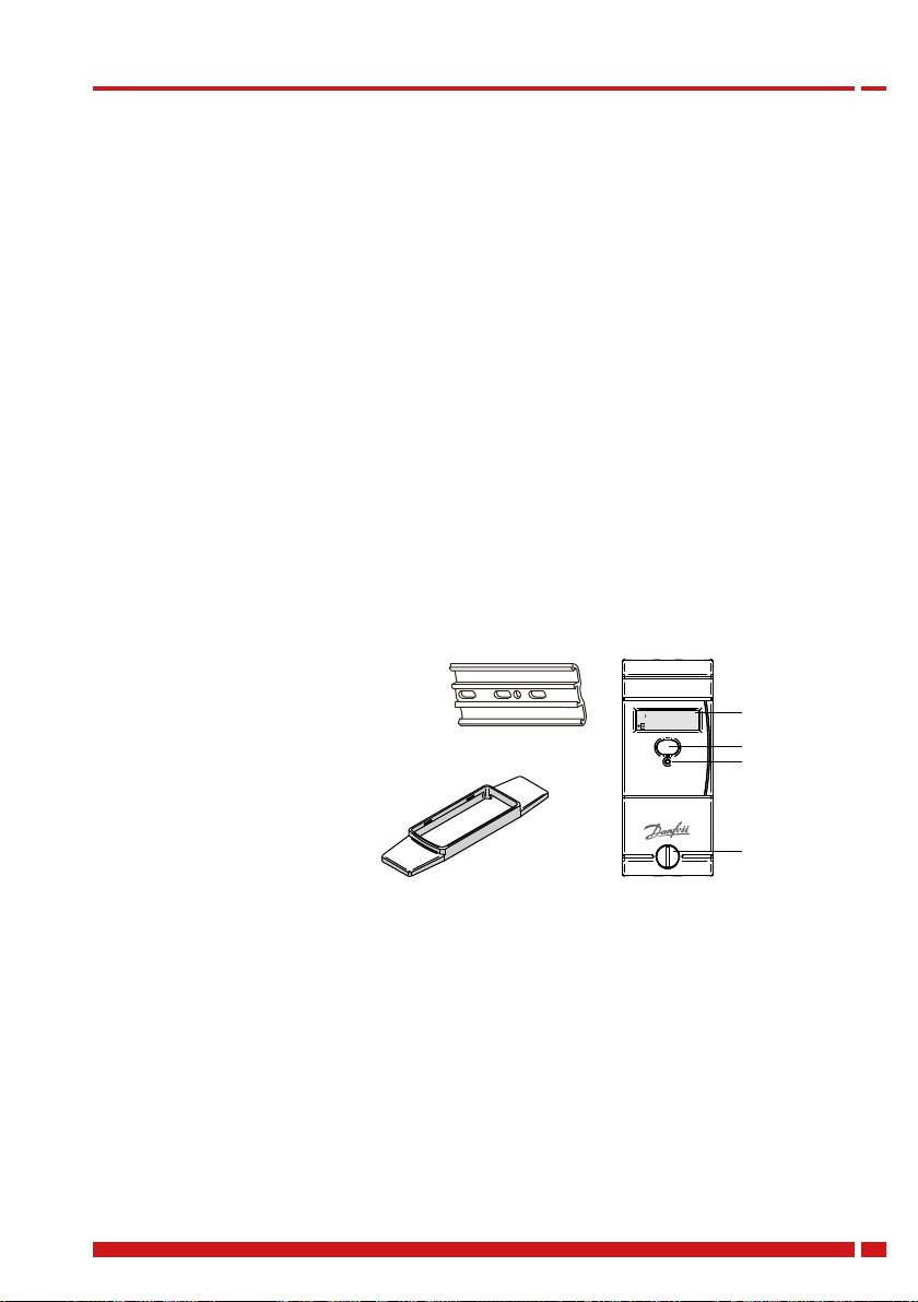
Design
The heat cost allocator consists of a microprocessor, a lithium battery, two temperature
sensors, a heat conducting aluminium back plate, a multi-functional display and a plastic
housing.
The measuring circuit consists of the temperature sensors, the analogue-digital conversion,
the reference resistance for standardising the measuring transformation and the microprocessor for accessing the radiator heat output.
During each measuring the circuit tolerances are eliminated with
a reference resistance and the
heat cost allocator carries out an
automatic self-test.
Standard aluminium back plate
for nearly all existing bolts with
common dimensions and mounting
possibilities – thus easy installation.
Snap-on blind to cover colour
shadows for increased aesthetics.
::
LCD-Display
Optical Interface
Push Button
Seal
Versions
• Heat cost allocator INDIV-X-10V with optical interface, standard device.
• Heat cost allocator INDIV-X-10VT with optical interface, remote sensor device with 1.5 m
cable.
• Radio heat cost allocator INDIV-X-10W with optical interface, standard device.
• Radio heat cost allocator INDIV-X-10WT with optical interface, remote sensor device with
1.5 m cable.
Characteristics
• Measuring by two temperature sensors, radiator and ambient temperature sensor
(NTC-resistor)
• Optional measuring principle: 1 sensor mode with start sensor or two sensor mode
• Unit scale or product scale
• Recording of cumulated heat consumption on the annual set day
Danfoss Heating VUIGA102
3
Page 4
1.0 Specification
• Recording of 36 monthly values or 18 monthly and half monthly values
• Optical interface for the readout of the data and programming
• Readout via radio optional with a mobile radio modem or directly by the billing office over
the radio central installed outside the unit
• User-friendly operation by push button
• 6-digit and high-contrast LCD display
• Check code for postcard mail-in method
• Remote sensor version with 1.5 m cable
• Standard aluminium back plate for nearly all existing bolts with common dimensions and
installation possibilities – thus easy installation (no cutting and welding of bolts necessary)
• Snap-on blind to cover colour shadows for increased aesthetics
• Safe operation and fraud detection
• Factory seal protecting against unauthorized manipulation
• Possibility to use seal sticker as second seal for further protecting against manipulation
• Lithium battery with a capacity of up to 10+1 years
• Meets EN 834:2013
Display
The heat cost allocator has a LCD-display with 6 large main digits on the right and 2 smaller
digits on the left as well as two special symbols and one communication indicator. The main
digits are separated by four decimal points. Below, please find the display segments:
::
Normally, the heat cost allocators INDIV-X-10V / INDIV-X-10W are supplied with switched-off
LCD-display. On request, the heat cost allocators can also be supplied with permanent LCDdisplay.
Optical Interface
With a standardised optical probe the consumption and configuration values can be
transferred directly to a computer. With the radio heat cost allocator INDIV-X-10W all
consumption values can thus be readout over the optical interface and over radio. The
data are transmitted in M-bus-format acc. to EN1434. Authorised personnel can alter the
configuration of the device over the optical interface with an optical probe.
Radio Transmission
The radio heat cost allocator INDIV-X-10W features a transceiver circuit in the 433 MHz
band with integrated antenna. With the radio system, proven since more than 10 years; it is
possible to readout the consumption values via a mobile radio modem or via a radio central
installed directly in the office. The radio system is a bidirectional system, i.e. the radio heat
cost allocator is only called from a mobile PDA or a radio central upon request to send its data.
It is a great advantage that this system allows the alteration of the parameters over radio.
VUIGA102 Danfoss Heating
4
Display with all active segments
Page 5

1.0 Specification
1.2 Operating mode
Cycle Time
Every 4 minutes the device is set into operation and operates according to the adjoining
diagram.
The tasks carried out during one cycle are taking approx. 200 ms. This means that the device
is in sleeping mode more than 99.8 % of the time. It can be set into operation between
two cycles over the optical probe or by pushing the button. In this case it carries out the
requested task and then returns to sleeping mode.
In case an optical probe is connected or the button is pushed during the course of the cycle,
the respective value is readout at the end of the cycle.
The button should not be pushed indefinitely to avoid a mechanical damage. The optical
probe can be left in its position since the normal function of the device is not impaired by an
influence from outside.
Heat Accumulation Mode
In order to avoid faulty measuring due to heat accumulation (e.g. in case the radiator is
hidden by panels), the device switches from a defined ambient temperature (e.g. 28°C) to the
one sensor mode and calculates with an ambient temperature of 20° C.
Comparison of the Measuring Principles
Single sensor device with start sensor
Double sensor measuring principle
measuring principle
For heating systems with tm
≥ 55 °C
min
The heat cost allocator calculates with a set
reference temperature of 20 °C
Application:
Single sensor devices with start sensor
are used in areas where normal ambient
temperatures are given. For low temperature
heating systems the double sensor device is
recommended.
For radiators which are covered or blocked
by fixtures, normally the single sensor
devices are used because the double sensor
For heating systems with tm
≥ 35 °C
min
The heat cost allocator calculates with a
variable reference temperature T
air temperature
Application:
Double sensor devices are used in areas
where precise measuring of the ambient
temperature is necessary and/or in low
temperature heating systems.
Radiators which are covered or blocked by
fixtures are detected automatically by the
double sensor system which then switches
over internally to the single sensor mode.
device is not in a position to capture the
current ambient temperature due to the
heat accumulation.
Within one billing unit, only one measuring principle (either single sensor
measuring principle with start sensor or double sensor measuring principle) can be
used. Mixed fitments or the use of different types of devices in the same billing unit
is therefore not allowed.
Danfoss Heating VUIGA102
5
Page 6
1.0 Specification
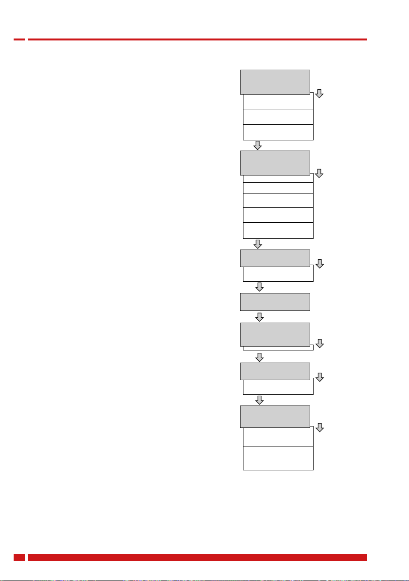
1.3 Digital Display and functions
The menu sequences
Ex factory all menu sequences are activated. With the
software INDIV-X-VISUAL-CONF the order of the menu
sequences 1 - 7 can be changed in any order. However the
order within the individual menu sequences 1 - 7 cannot
be changed. It is also possible to hide individual menu
sequences so that they are not visible to the end-user.
When reading out over the optical interface or via
radio the complete set of data is always readout and
transferred.
Operation of the Push Button
When pushing the button briefly the digital display
always goes to the next menu sequence.
When pushing the button in one menu sequence for
2 seconds the individual values within the selected
menu sequence can be accessed. When the last value
within one menu sequence has been displayed, the next
menu sequence can be reached by pushing the button
again.
If the button is not pushed for 2 minutes, the digital
display returns to the cumulated consumption value.
The Digital Displays
During normal operation the display is deactivated and
can be activated by pushing the button. On request, the
heat cost allocator is also available with permanent
display from 06:00 - 20:00 h or 24 hours a day. The
consumption value is displayed. By pushing the button
and depending on the configuration of the heat cost
allocator more than 50 different values can be displayed.
If the button is not pushed, the display will be active for
2 minutes only. Exception: permanent display mode.
The current and monthly values recorded by the heat
cost allocator INDIV-X-10V and INDIV-X-10W as well as
several other parameters can be readout over the optical
interface or also over radio with the heat cost allocator
INDIV-X-10W (see description below).
Comsumption value
Set day value
Check code
Value on December 31st
or before the reset to 0
Short key press
Current time
Current date
Set day date
Date of opening of the
device
Commissionen date
Cumulated duration of the
opening of the device
Short key press
Set day value
Check code
Short key press
Check code
Short key press
Monthly values
Short key press
Radiator temperature
Ambiant temperature
Short key press
Segment test
Identication number
Measuring principle +
software version
Display position 1
Long key press
Display position 2
Long key press
Display position 3
Long key press
Display position 4
Display position 5
Long key press
Display position 6
Long key press
Display position 7
Long key press
Energy-Saving Night Mode between 20.00 and 6.00 h
If the LCD-display is activated, the heat cost allocator switches automatically to the
energy-saving night mode between 20.00 and 06.00 h (winter time). During this period the
LCD-display is deactivated and switched off generally.
VUIGA102 Danfoss Heating
6
Page 7
1.0 Specification
Consumption Value Unit Scale
Consumption Value Product Scale
Set Day Value
On the display of the heat cost allocator with unit scale
an index u for unit is shown on the left side. If the index
u is not displayed, the heat cost allocator is equipped
with the product scale.
When commissioning the device this value is 000000.
When reaching the value 999999, the counting restarts
automatically at 000000.
With the index ud the consumption value recorded at
midnight of the set day is displayed.
Check Code
If a new device has not yet reached the programmed
set day, 000000 is displayed.
With the index cc the check code for the plausibility
check of the manual readout is displayed.
With especially developed algorithms a 6 digit check code is generated out of several device
data. With this check code the values stated on the postcards mailed-in by tenants can be
cross checked.
For the verification of the check code Danfoss places all necessary tools (programmes,
formulas) at the disposal of the authorised personnel.
Consumption Value of the
Previous Heating Period
With the index uI the consumption value is displayed
Time
which was recorded on December 31st or before the
reset to zero.
000000 is displayed on a new device as long as a reset
has not been carried out.
The current time (always winter time)
:
Danfoss Heating VUIGA102
7
Page 8
1.0 Specification
Date
..
Set Day
..
Date of Opening of the Device
..
Commissioning Date
..
Cumulated Duration of the
Opening of the Device
Identification Number
Monthly Values
The current date of the heat cost allocator
It is possible to program an annual set day on which
the cumulated consumption value as well as the
maximal radiator temperature are recorded.
With the index Sd the programmed annual set day is
displayed.
Each heat cost allocator is equipped with a
manipulation protection which detects an
unauthorised opening of the device after installation
to the radiator. The date of the opening of the device is
recorded and displayed with the index od.
With the index cd the commissioning date is displayed,
i.e. the date on which the device has been activated
by pushing the button or the date of commissioning
programmed ex factory.
The cumulated duration in minutes during which
the device was opened is detected. This display turns
up only after commissioning in case the heat cost
allocator was opened or removed.
With the index
displayed. Ex factory the serial number is identical with
the identification number. The first two digits of the
identification number are the two small digits on the
left upper side of the digital display.
The cumulated consumption values are recorded
automatically at midnight on the last day of each
month.
Number of monthly values: 18 or 36
an 8 digit identification number is
VUIGA102 Danfoss Heating
8
Page 9
1.0 Specification
Values
Half Monthly Values
Radiator Temperature
.
Ambient Temperature
.
Maximum Radiator Temperature
of the Current Heating Period
.
The small digits on the upper left side show the
number of previous monthly values. Digit 01 stands
for the recent full month and digit 18 or 36 stands for
the least recent month. All monthly values are set to
000000 when the device is commissioned.
Note INDIV-X-10W radio:
The radio heat cost allocator INDIV-X-10W only
transmits the first 16 monthly values via radio
telegram.
The cumulated consumption values are recorded
automatically at midnight on the 16th of each month.
The small digits on the upper left side indicate the
number of half monthly values. Digit 41 stands for the
recent half monthly value and digit 58 for the least
recent half monthly value. All half monthly values are
set to 000000 when the device is commissioned.
If the heat cost allocator INDIV-X-10V is programmed
with 36 monthly values the menu sequences for the
half monthly values are omitted.
Note INDIV-X-10W radio:
The heat cost allocator INDIV-X-10W does not
transmit the half monthly values via radio telegram.
With the index tH the current radiator temperature is
displayed.
With the index tA the current ambient temperature is
displayed.
With the index P0 the maximum radiator temperature
since the last reset or of the current heating period is
displayed.
Danfoss Heating VUIGA102
9
Page 10

1.0 Specification
Maximum Radiator Temperature
of the Previous Heating Period
.
Measuring Principle and
Software Version
.
Segment Test
With the index P1 the maximum radiator temperature
before the last reset or of the previous heating period
is displayed.
With the index F1 or F2 the measuring principle is
displayed.
F1 = single sensor device with start sensor
F2 = double sensor device
On the right side the software version x.xx of the heat
cost allocator is displayed.
Segment test of the display
::
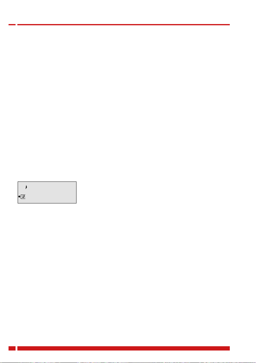
Error Message
Communication Indicator
The communication indicator displays if the heat cost allocator is currently making a
calculation and/or if it communicates internally or externally over the optical or wireless
interface.
If an error is detected, Err is displayed in the first
display sequence with the corresponding error
message.
If the arrow of the communication indicator points
inwardly internal communication takes place over the
optical or wireless interface.
If the arrow of the communication indicator points
outwards external communication takes place over the
optical or wireless interface.
If the frame of the communication indicator appears
the heat cost allocator is carrying out a measuring or
a calculation.
VUIGA102 Danfoss Heating
10
Page 11

1.0 Specification
Real Time Clock and Calendar
The device has a 24 h real time clock and a calendar. However, the change from summer to
winter time is not taken into account. The calendar is programmed until December 31, 2099,
including all leap years. The real time clock as well as the date of the heat cost allocator can
be readout over the optical interface or via radio and if necessary be updated.
If the current date and time have to be updated over the optical interface or via radio,
it is necessary to check the date of the computer first. Date and time of the device aim
at those of the computer. If the reading/programming device (computer/PDA/ Smart
Phone) has a wrong time, this time will be programmed into the heat cost allocator
and suddenly no longer be reached at the usual time, because the time of the heat
cost allocator possibly is shifted by several hours.
Change of Battery
The battery of the heat cost allocator is soldered. The lithium battery is not rechargeable.
A change of battery is not planned. Therefore the heat cost allocators have to be replaced
after 10 years.
Disposal
It is mandatory to dispose of the heat cost allocator environmentally
friendly or to return it after use to the manufacturer for appropriate
disposal to ensure that the components are recycled in accordance
with the battery and electronic scrap regulations. Should you do the
disposal yourself please get information from your local authority on the
recycling possibilities.
1.4 Protection against Outside Influences
Seal and seal sticker
The heat cost allocator is closed with a seal which cannot be removed without damaging it.
Thus it is impossible to open the device unnoticed.
A seal sticker as second seal is used for further protecting against manipulation. After
mounting, the seal sticker is fixed between housing of heat cost allocator and aluminium
back plate. Heat cost allocator cannot be removed from aluminium back plate without
damaging a sticker.
After installation, the electronic part of the device is no longer accessible. The digital display,
the push button and the optical interface are covered by a sight glass. It is impossible to
access the inside of the device through these openings without damaging the sight glass.
Electronic Detector in Case of an Opening of the Device
The electronic detector detects unauthorised opening, removing and closing of the heat
cost allocator. As soon as the housing of the heat cost allocator is opened and/or removed,
the electronic detector triggers an error message. The duration of each opening is counted,
cumulated and only the last date of opening recorded.
Danfoss Heating VUIGA102
11
Page 12

1.0 Specification
Suppression of Summer Counting
The period during which summer counting is suppressed can be programmed by the
software.
If the heat cost allocator is in the period of summer counting suppression, consumption
measuring is deactivated. If an automatic readout is carried out during this period the
temperatures can be read anyway since the temperature measuring is still active.
If the special function „suppression of summer counting“ is activated, the homologation
acc. to EN 834 is void. This special function is not included in the applicable standard.
Unit Scale and Product Scale
For the heat cost allocators INDIV-X-10V and INDIV-X-10W, distinction is made between the
unit scale and the product scale.
If heat cost allocators are used with the same scale on all radiators, this scale is called unit
scale. The display values are the same on the different radiators if the heat cost allocators are
exposed to the same temperature for the same period of time.
The evaluation of the display values is carried out arithmetically with the rating factors of the
calculation software to receive the final consumption values.
List of Errors
Err.001 Manipulation (fraud) ! Disabled with remote sensor version !
Err.002 Measuring error
Err.008 Only INDIV-X-10W: error EEPROM, error of radio communication
Err.016 Error of digital display – the data to be processed cannot be displayed
Err.032 Button pushed constantly
Err.064 Measured temperature not within temperature range (0..105°C; 0..120°C
remote sensor). Cable of remote temperature sensor are in contact
(short-circuited).
Err.066 Cable of remote temperature sensor are not in contact.
Radio Standby – Radio-HCA INDIV-X-10W
In order to achieve a user-friendly and power-saving radio standby, the radio heat cost
allocator features the following different operating modes:
midnight
Sleeping mode Installation mode Operation mode
Transition from sleeping mode to installation mode is
achieved by pushing the button once or by reaching the
programmed commissioning date
Sleeping Mode
Ex factory the radio heat cost allocator INDIV-X-10W is in sleeping mode, but the internal
clock and the date are running.
VUIGA102 Danfoss Heating
12
Page 13

1.0 Specification
Current consumption is reduced to a minimum since no measuring and no calculations are
carried out and furthermore communication options are not assisted.
Transition from sleeping to installation mode is achieved by pushing the button once or by
reaching the programmed commissioning date.
Installation Mode
During the installation mode all functions of the radio heat cost allocator are carried out and
radio transmission is possible for max. 24 hours. This guarantees an optimal availability of the
radio heat cost allocator for test purposes during installation.
The radio heat cost allocator remains in installation mode until midnight and then switches
over automatically to operation mode.
1.5 Operation Mode
Walk-By Radio Remote Readout
A walk-by remote readout of the data of the heat cost allocator INDIV-X-10W is possible every
day from 6.00 to 17.58 (winter time).
No readout possible between 18.00 and 20.00 (winter time)!
Readout over Radio Central (installed directly in the building)
For the readout over a radio central installed in the building, the following applies (see table
below):
The device with the corresponding final numeral of the serial number is ready for radio
transmission during the time stated in the table below.
Time Serial Number
20:00 – 20:58 XXXXXXX0
21:00 – 21:58 XXXXXXX1
22:00 – 22:58 XXXXXXX2
23:00 – 23:58 XXXXXXX3
00:00 – 00:58 XXXXXXX4
01:00 – 01:58 XXXXXXX5
02:00 – 02:58 XXXXXXX6
03:00 – 03:58 XXXXXXX7
04:00 – 04:58 XXXXXXX8
05:00 – 05:58 XXXXXXX9
After readout of the data from the radio heat cost allocator, the radio availability is
deactivated again.
Danfoss Heating VUIGA102
13
Page 14

2.0 Installation
2.1 Introduction
To guarantee the proper functioning of the heat cost allocator INDIV-X-10V and INDIV-X-10W,
it is of great importance that it is installed by an expert. On one hand, a constant heat transfer
between radiator and heat cost allocator has to be guaranteed. On the other hand, the
installation of the heat cost allocators to a large variety of radiator types should be as easy as
possible.
The installation can be carried out in two different ways. The standard device is installed
directly to the radiator. For the wall-mounted version the remote sensor is installed to the
radiator and the heat cost allocator is wall-mounted. For the installation of the heat cost
allocators, special fastening-parts kits are available.
To avoid faulty installation, we also recommend reading the Kc-data in the data base prior to
the installation.
The heat cost allocator is an electronic device which – like all other similar devices – has to
be handled with care. It is sensible to electric discharge and contacting certain areas of the
PCB. Electric discharge can destroy the device or – even worse - damage it in a way that it fails
after an indefinite period of time.
For this reason it is essential to avoid contact with the PCB.
DIN Standard Requirements for the Installation
a. Heat cost allocators can be installed in heating systems where the mean design heating
medium temperature is between the upper operating temperature limit tmax and the
lower operating temperature limit tmin (tmax and tmin are stated in the technical data,
see enclosure)
b. The installation of the devices has to be durable and safe against manipulation.
c. The devices have to be installed in a place where sufficient correlation between the
displayed value and the heat output of the radiator is given over a maximum operating range.
d. Within one billing unit (in case of pre-distribution of the energy consumption: within one
users’ group) only heat cost allocators of the same make and the same type with identical
rating systems may be used. Each device type has to be identifiable as such.
e. Combinations of radiators and heat cost allocators with a measured value of c > 0.3 in
basic condition are not permitted. In exceptional cases c-values of up to 0.4 are permitted
within one billing unit if the concerned heating surface does not exceed 25 % of the
overall heated surface or if the mean design heating medium temperature is above 80°C.
Heat cost allocators may only be installed to radiators where the c-value is known at the
time of billing.
General Restrictions
Electronic heat cost allocators cannot be used with steam heating, floor heating, ceiling
radiant heaters and flap-controlled radiators.
In case of combined valve- and flap-controlled radiators, the installation of an electronic heat
cost allocator is only permitted if the flap control is dismounted or shut down in position „open“.
Convector heaters where the performance can be altered by an electric blower as well as
heat towel racks with an electric heating cartridge may only be equipped with an electronic
heat cost allocator if the additional electric attachments are dismounted or shut down.
VUIGA102 Danfoss Heating
14
Page 15

2.0 Installation
Operating Range
The heat cost allocators can be used in heating systems with the following mean heating
medium temperatures:
For single sensor devices with start sensor
55°C…105° C for standard heat cost allocator
55°C…120°C for wall-mounted heat cost allocator (remote sensor)
For double sensor devices
35°C…105° C for standard heat cost allocators
55°C…120°C for wall-mounted heat cost allocators (remote sensor)
A heat cost allocator can be used in heating systems where the suitability of the system is in
line with the operating conditions for which the heat cost allocator has been approved.
Please refer to standard EN 834 for the definition of the terms.
2.2 Mounting
Installation to the Radiator
The heat cost allocator is always installed in
the middle of the overall length (0,5 x BL) of
the radiator at a height of ¾ of the overall
height (0,75 x BH) measured from the bottom
to the small round whole in the middle.
If the height of the radiator is less than (<)
470 mm, the heat cost allocator must be
installed at 50% BH.
If the radiator has an even number of sections
the heat cost allocator is installed between the
middle sections. If the radiator has an uneven
number of sections the device is installed next
to the valvesided middle section.
When welding the heat cost allocator the
upper threaded bolt has to be welded from
the bottom side in the middle of the overall
length (0,5 x BL) and at a height of (0,75
x BH) + 2 cm. The lower bolt is positioned
vertically 5 cm below the upper bolt and
welded. Before welding the lacquer has to be
removed from the welding points. Attention
has to be paid that the bolts are welded onto
a water-bearing area or a flute.
0,5 x BL
0,5 x BL
0,5 x BL
0,5 x BL
5 cm
0,75 x BH
(0,75xBH)+2 cm
Danfoss Heating VUIGA102
15
Page 16

2.0 Installation
Only use M3 bolts with a maximum length of 8 mm or there’s a risk that the device will be
damaged. Mount the back plate through the 2 oval holes, adjusted to the top edge of the 2
ovals holes.
If the radiator is of a length of more than 3 m, two heat cost allocators have to be installed.
This radiator is thus regarded as two series connected individual radiators which however are
individually.
Example of 2 heat cost
allocators
0,75 x BH
Mounting: 0.75 X BH + 2 cm
to the upper bolt
0,25 BL
0,25 BL
0,75 BL
Wall-Mounting
The heat cost allocator has to be wall-mounted if the overall height of the radiator is less than
250 mm or if, for aesthetical reasons, the heat cost allocator cannot be mounted directly onto
the radiator.
In this case, the heat cost allocator is wall-mounted on the side opposite to the valve and at a
minimum distance from the radiator of 10 cm.
at least
10 cm
at least
10 cm
After marking and drilling the holes, the alu minium profile is fastened with 2 sheet metal
screws and 2 spring washer.
VUIGA102 Danfoss Heating
16
Page 17

2.0 Installation
The parts necessary for the wall-mounting are
included in the corresponding fasteningparts
kits for the installation of the remote sensor.
After installation of the device to the wall and
the sensor to the radiator, the sensor cable is
088H2424
088H2345
088H2420
088H2423
laid in a cable duct.
Mount the back plate through the 2 oval holes adjusted to the top edge of the 2 oval holes.
Mounting Accessories Code No.
2 plastic dowels Ø5 mm 3.25 088H2424
2 spring washers 088H2420
2 oval head wood screws 3 x 35 088H2423
1 aluminium back plate (supplied with EHCA) 088H2345
Installation of Fastening-Parts Kits
Installation to Sectional Radiator
For radiators made from cast iron it is necessary
088H2408
to apply heat transfer compound (Electrolube
HTS) onto the contact surfaces of the alu-
088H2345
minium profile before installation. Mount the
back plate through the little hole in the middle.
088H2420
088H2412
Mounting Accessories Code No.
1 tensioning bracket 088H2408
1 aluminium back plate (supplied with EHCA) 088H2345
1 cylinder head screw M4 x 40 088H2412
1 spring washer B 4 088H2420
Danfoss Heating VUIGA102
17
Page 18

2.0 Installation
Wall-Mounting - Sectional Radiator
The remote sensor has to be
fixed in the receiver housing
with adhesive to avoid
loosening.
0088H2408
The contact surfaces of the
cover angles have to be coated
with adhesive before bringing
them together.
Remote
sensor
088H2410
088H2420
088H2412
088H2406
After mounting, it is possible to
fix a seal sticker on the receiver
housing.
Mounting Accessories Code No.
1 tensioning bracket 088H2408
1 aluminium profile „receiver housing“ 088H2410
1 spring washer B 4, DIN 128 088H2420
1 cylinder head screw M4 x 40 (with crosshead) 088H2412
2 cover angles, white 088H2406
2 plastic dowels Ø5 mm 3.25 (wall) 088H2424
2 oval head wood screws 3 x 35 (wall) 088H2423
Installation to Folded Radiator
Mount the aluminium
back plate through the
088H2413
088H2421
small round hole
088H2345
088H2420
088H2411
Mounting Accessories Code No.
1 hexagon nut B M4, DIN 934 088H2413
2 bracing angles 088H2421
2 spring washers B4, DIN 128 088H2420
1 oval head screw M4 x 30 088H2411
1 aluminium back plate 088H2345
VUIGA102 Danfoss Heating
18
Page 19

2.0 Installation
If necessary use 2 x 2 bracing angles to improve more stability (picture) and, if needed,
short the screw.
Mounting Accessories Code No.
2 hexagon nut B M4, DIN 934 088H2413
2 x 2 bracing angles 088H2421
4 spring washers B4, DIN 128 088H2420
2 oval head screw M4 x 30 088H2411
1 aluminium back plate (supplied with EHCA) 088H2345
Wall-Mounting – Folded Radiator
The remote sensor has to be fixed in
the receiver housing with adhesive
to avoid loosening.
088H2415
The contact surfaces of the cover
angles have to be coated with
adhesive before bringing them
together.
088H2414
088H2409
088H2405
088H2407
After mounting, it is possible to fix a
seal sticker on the receiver housing.
Mounting Accessories Code No.
1 tensioning nut 088H2415
1 tensioning bolt 088H2414
1 aluminium profile « receiver housing» 088H2409
1 safety plate 088H2405
2 cover angles, white 088H2407
2 plastic dowels Ø5 mm 3.25 (wall) 088H2424
2 oval head wood screws 3 x 35 (wall) 088H2423
Danfoss Heating VUIGA102
19
Page 20

2.0 Installation
Installation to Panel-Type Radiator
Mount the back plate through the
2 oval holes adjusted to the top
088H2422
edge of the 2 oval holes
088H2345
088H2418
088H2416
Mounting Accessories Code No.
2 threaded bolts M3 x 8 (see page 15!) 088H2422
2 spring washers B3, DIN 137 088H2418
2 slotted nuts M3, DIN 546 088H2416
1 aluminium back plate (supplied with EHCA) 088H2345
Tool: Screw driver size 5 for M3
or
Mounting Accessories Code No.
2 threaded bolts M3 x 8 (see page 15!) 088H2422
2 Nuts M3 6-kant size 5.5 with flange
1 aluminium back plate (supplied with EHCA) 088H2345
Tool: Socket wrench hexagonal size 5.5
or
Mounting Accessories Code No.
2 threaded bolts M3 x 8 (see page 15!) 088H2422
2 Nuts M3 mit 6-kant size 5.5
1 aluminium back plate (supplied with EHCA) 088H2345
Tool: Socket wrench hexagonal size 5.5
VUIGA102 Danfoss Heating
20
Page 21

2.0 Installation
Wall-Mounting - Panel-Type Radiator
The remote sensor has to
be coated with heat transfer
compound (Electrolube HTS)
on the contact surface.
¼ BH**
or
½ BH**
Mount the back plate through
the 2 oval holes adjusted to the
top edge of the 2 oval holes
20 mm
088H2424
088H2345
088H2420
088H2423
088H2422
Remote
sensor
088H2417
088H2404
Remain inside sensor
Detached part
Mounting Accessories Code No.
2 threaded bolts M3 x 8 088H2422
2 pull-off nuts M3 088H2417
1 HK-sensor cover 088H2404
2 plastic dowels Ø5 mm 3.25 (wall) 088H2424
2 oval head wood screws 3 x 35 (wall) 088H2423
Installation to Panel-Type Radiator with Front Convection Plate
The contact surfaces of the
aluminium screws have to be
coated with heat transfer compound
(Electrolube HTS).
The aluminium screws have to be
fastened with adhesive to avoid
loosening.
Danfoss Heating VUIGA102
088H2425
088H2419
21
Page 22

2.0 Installation
Mounting Accessories Code No.
3 sheet-metal screws 2.9 x 9.5 088H2419
1 aluminium back plate 088H2425
Bathroom radiator – Towel rails
Heat cost allocator mounted vertically on distributor or collector part
Assembly with 2 threaded bolts welded
on 75% BH +50mm on the side or
front of the flow distributor or return
collector.
Mounting Accessories Code No.
2 threaded bolts M3 x 8 (see page 15!) 088H2422
2 spring washers B3, DIN 137 088H2418
2 slotted nuts M3, DIN 546 088H2416
1 aluminium back plate (supplied with EHCA) 088H2345
Tool: Screw driver size 5 for M3
Heat cost allocator mounted horizontally on cross tubes
Assembly to the nearest possible
place to the flow place or return place
on the cross tubes on 75% BH with 2
tensioning brackets.
VUIGA102 Danfoss Heating
22
Page 23

2.0 Installation
Mounting Accessories Code No.
2 tensioning bracket 088H2408
1 aluminium back plate (supplied with EHCA) 088H2345
2 cylinder head screw M4 x 40 088H2412
2 spring washer B 4 088H2420
Sectional radiator wide
Mount the back plate through the 2
oval holes adjusted to the top edge
of the 2 oval holes.
Mounting Accessories Code No.
2 tensioning bracket 50mm 088H2428
1 aluminium back plate (supplied with EHCA) 088H2345
1 heat conductor aluminium plate 60mm 088H2427
2 cylinder head screw M4 x 40 088H2412
1 cylinder head screw M3 x 10 088H2429
1 Nut M3 088H2430
088H2428
088H2430
088H2427
088H2345
088H2412
088H2429
Mounting and Sealing
After installation of the respective fastening-parts kit to the radiator, the heat cost allocator
can be mounted and sealed as described below.
1. The heat cost allocator is placed at the upper end of the aluminium back plate. Move the
heat cost allocator down so that the hooks in the housing fit in the aluminium back plate.
2. The heat cost allocator is swinged on the aluminium back plate in the direction of the
arrow.
3. Introduce the seal in the slot of the housing, then press until the seal clicks into the
aluminium back plate.
Now the heat cost allocator can only be opened by destroying the seal.
Danfoss Heating VUIGA102
23
Page 24

3.0 Commissioning and Readout
2.
3.1 Commissioning
1.
Ex factory the heat cost allocators
INDIV-X-10V and INDIV-X-10W are in the
so-called sleeping mode. In this mode
no measuring is carried out and thus
no consumption values are calculated.
Furthermore the digital display, the
communication options as well as
the device opening detection are
deactivated.
The date and time are running in the background.
The measuring mode is set off by pushing the button
or when reaching the programmed commissioning date.
Heat cost allocator INDIV-X-10W: in addition to the
measuring mode, the installation mode is activated as
well. During installation mode the radio transmission is
possible for max. 24 hours.
The measuring mode is set o
by pushing the button (> 2 s)
After the commissioning and before leaving a
new site, we recommend to perform a radio read
or when reaching the
programmed commisioning
date.
out test and to create an installation protocol,
to ensure that all the radio communication
between the heat cost allocators and the radio
central or radio modem was successful.
After midnight the radio heat cost allocator INDIV-X-10W changes automatically from
installation to operation mode.
3.2 Readout
Manual Readout
The recorded consumption values can be displayed by pushing the button. (see chapter:
Digital Display and functions)
Then the displayed values are copied to a data collection sheet or entered into a portable
data acquisition device.
Optical Probe
The hardware of the optical bidirectional interface which is built in the device is in line with
standard EN 61107, 9.1992, part 3.2.
The optical probe is positioned on the front side of the device in the round cavity below
the display. The position of the connecting cable is irrelevant. Thus access to the device is
guaranteed even under difficult conditions.
VUIGA102 Danfoss Heating
24
Page 25

3.0 Commissioning and Readout
Remote Radio Readout
Danfoss expressly points out that the data transmission via mobile radio modem
depends on the radio propagation conditions existing at the installation point and that
under certain atmospheric or geographic conditions (especially within secluded areas
as well as in so-called radio shadows) mobile radio connections cannot be established
at any time and at any place. It is solely incumbent on the user to check the radio
propagation conditions at the planned installation point.
Mobile Readout
The mobile radio readout of the radio heat cost allocator INDIV-X-10W is done via the mobile
radio modem which is equipped with a transceiver including antenna for radio transmission.
The radio modem operates at the frequency of 433.82 MHz and is combined with a PDA.
Danfoss program for the readout and parameterisation features the following main functions:
• Readout and display of an individual radio heat cost allocator
• Readout and display of a group of radio heat cost allocators
• Adding of devices in a router file
• Removing of devices in a router file
• Parameterization of an individual or a group of heat cost allocator via radio
Stationary Readout
With the stationary readout, the radio central receives the data from the radio heat cost
allocator or other devices which are equipped with radio. The data recorded in the radio
central can be readout over a RS-232 interface, a M-bus, a modem or a GPRS-module.
Rating factors
Taking Measurements
The value displayed by the heat cost allocator has to be converted to the value of the actual
heat output of each radiator. Thereby the design and the performance of the radiator as well
as the mode of installation have to be taken into account.
Therefore each radiator has to be identified precisely by taking measurements. The following
data have to be established:
• Design and make of radiator
• Overall length
• Overall height
• Overall depth
• Number of sections
• Pitch
• In-line configuration
Rating of Radiators of Over Length or High Nominal Output
If the radiator has an overall length of approx. 3 m we strongly recommend installing two
heat cost allocators.
Under certain circumstances minimal flows might not be noticed on these radiators.
The same applies for radiators with an extremely high nominal output of more than
10.0000 watt = 10kW.
Danfoss Heating VUIGA102
25
Page 26

4.0 Technical Data and Dimensional Drawing
At least two heat cost allocators should be installed to these radiators. The standard
performance of each radiator is divided by the number of heat cost allocators installed.
Table of rating factors
A detailed summary of the Kc-values is available in an Excel-file on request.
Technical Data
Optional measuring systems: Single sensor device with start sensor
for heating systems with tm
≥ 55 °C
min
Calculation with set reference temperature
20 °C
Necessary rating factors: KQ, KC, (KA, KT)
Double sensor device
for heating systems with tm
≥ 35 °C
min
Calculation with variable ref. temperature
T-air sensor
Necessary rating factors: KQ, KC, (KA, KT)
Optional scales: unit scale or product scale
Current supply: 3 V-Lithium-battery
Life-span with 1 battery: > 10 years
Display: liquid crystal display (LCD-display)
No. of displayed digits: 6 digits (000000 ... 999999)
Sensor temperature range: 0 °C ... 120 °C
Exponent: n = 1.33
Radiator – performance range: 4 Watt ... 16.000 Watt
Design temperature range: single sensor device with start sensor
(tm
... tm
min
) 55 °C ... 105°C / 120 °C (compact- / remote
max
sensor)
Double sensor system
(tm
... tm
min
) 35 °C ... 105°C / 120 °C (compact- / remote
max
sensor)
-values: Rating factors see digital KC-data base
K
C
Models: compact device or remote sensor device
Set day: freely programmable
Data storage: 36 monthly values or 18 monthly and half-
monthly values, maximum temperatures of
the current and previous year, all relevant
consumption values
Self-test: before every measuring
VUIGA102 Danfoss Heating
26
Page 27

4.0 Technical Data and Dimensional Drawing
Start of counting: heating period 25°C – 40°C (programmable)
Off-heating period 25°C – 40°C
(programmable)
Standard version: acc. to EN 834 :2013
Homologation acc. to
DIN registry No.:
Conformity: CE
Standard mounting height: at 75% of the overall height of the radiator
If the height of the radiator is less than (<)
470 mm, the heat cost allocator must be
installed at 50% BH. (in case of deviating
mounting heights, please refer to this
manual and the digital K
-data base
C
Weight: Max 52 g (Without back plate)
Dimensional Drawing
28
90.5
38
INDIV-X-10 device Remote temperature sensor
Danfoss Heating VUIGA102
8
28.7
4.5
27
Page 28
VUIGA102
Produced by Danfoss A/S © 12/2014
 Loading...