

Page 1
User Manual
Plus+1® Compliant
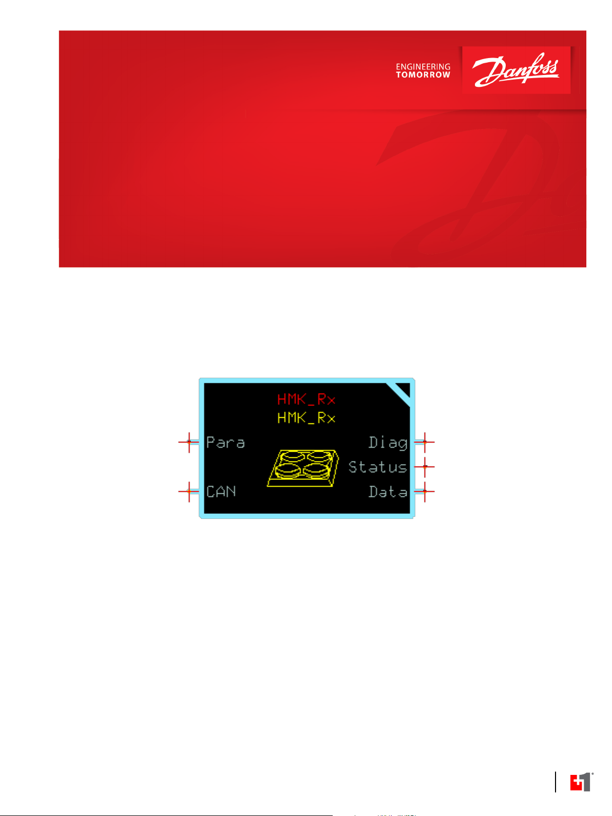
HMK_Rx Function Block
www.danfoss.com
Page 2

User Manual
Plus+1® Compliant HMK_Rx Function Block
Revision history Table of revisions
Date Changed Rev
April 2019 First edition 0101
2 | © Danfoss | April 2019 AQ299358258194en-000101
Page 3

User Manual
Plus+1® Compliant HMK_Rx Function Block
Contents
HMK_Rx
Overview..............................................................................................................................................................................................4
Inputs....................................................................................................................................................................................................4
Parameters..........................................................................................................................................................................................4
Outputs................................................................................................................................................................................................ 5
Diagnostic Signals............................................................................................................................................................................6
Status Logic........................................................................................................................................................................................ 7
Status Logic...................................................................................................................................................................................7
Instalation............................................................................................................................................................................................8
About the Namespace Feature.............................................................................................................................................. 8
How to Enter a Namespace Value.........................................................................................................................................8
HMK_Rx Service Screens................................................................................................................................................................9
©
Danfoss | April 2019 AQ299358258194en-000101 | 3
Page 4
User Manual
Plus+1® Compliant HMK_Rx Function Block
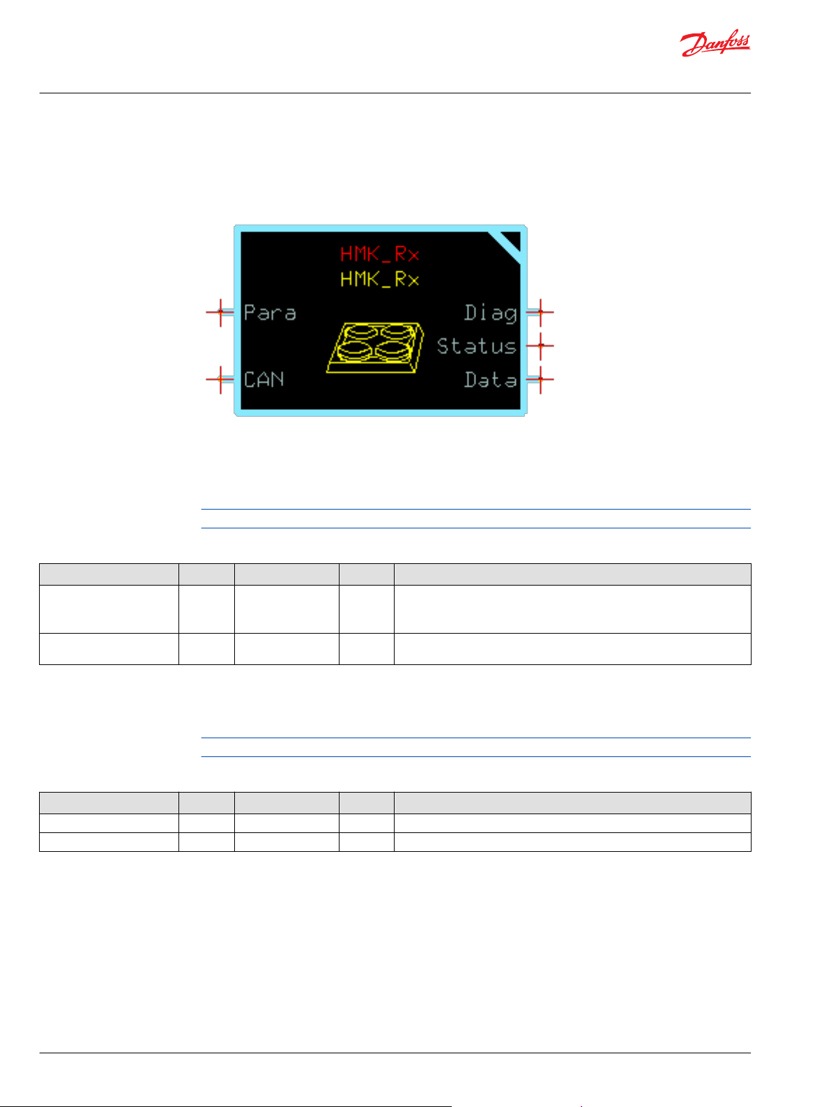
HMK_Rx
Overview
This function block configures the function for use with the HMK and is used to to receive the button
status.
Inputs
Entering the HMK_Rx function block gives an overview about the block’s signals.
To avoid compiler errors, use only the data types specified in this table.
Function Block Inputs
Input Type Range Unit Description
Chkpt BOOL T/F --
CAN.Port PORT -- -- Determines which physical CAN port of the hardware to receive data from.
Enables advanced checkpoints with namespace for each Diag signal.
T: Include checkpoints when compiled
F: Do not include checkpoints when compiled
This variable can be found in the CAN sub-bus if using the Main Template.
Parameters
Learn how the function block uses parameters to customize the function.
To avoid compiler errors, use only the data types specified in this table.
Function Block Parameters
Parameter Type Range Unit Description
Src_Addr U8 0 to 253 -- Source Address of the HMK.
Timeout U16 10 to 10000 ms Max time in ms between messages before a timeout fault is triggered.
4 | © Danfoss | April 2019 AQ299358258194en-000101
Page 5

User Manual
Plus+1® Compliant HMK_Rx Function Block
HMK_Rx
Outputs
Learn how the outputs of the function block work.
Function Block Outputs
Parameter Type Range Unit Description
Status U16 0, 0x8008 --
Button (1 to 16) BOOL T/F --
MsgTimedOut BOOL T/F --
NoMsgReceived BOOL T/F --
Diag BUS -- -- This bus provides diagnostic values for troubleshooting. In addition, all
Updated BOOL T/F -- True during the first programming cycle that new data is received.
This signal indicates if a parameter fault is declared. It’s a bitwise code, so
multiple items can be reported at a time. The following status codes are
provided:
0x0000: No fault
0x8008: At least one parameter is out of range
Reports the status of the respective button.
T: Pressed
F: Not Pressed
If the SignalName_NA is true, then the signal is not available. The
associated signal is set to false.
If the SignalName_Flt is true, then a fault condition currently exists for the
signal. The associated signal is set to false.
True if the time since the last status message has exceeded the value
determined by Timeout.
T: The message has timed out, block outputs set to zero/false, Flt signals
set true
F: No error
No message has been received from the device.
T: No message received since power on
F: A message has been seen since power on
inputs, parameters, and output signals are contained inside of the bus.
©
Danfoss | April 2019 AQ299358258194en-000101 | 5
Page 6

User Manual
Plus+1® Compliant HMK_Rx Function Block
HMK_Rx
Diagnostic Signals
Entering the Checkpoints page on the second level of the function block provides access to the block’s
diagnostic signals. It contains checkpoints on input, parameter, output, and internal signals. Only the
internal signals are explained below. Input, parameter, and output signals are described in the above
chapters.
Function Block Diagnostic Signals
Name Type Range Unit Description
CAN_RawData -- -- -- Data passed directly from the CAN receiver.
Btn_Encoded U16 0 to 65535 --
Packed button data. Bitwise code where multiple items can be reported at
a time.
T: Pressed
F: Not pressed
Bit 0: Button1
Bit 1: Button2
Bit 2: Button3
Bit 3: Button4
Bit 4: Button5
Bit 5: Button6
Bit 6: Button7
Bit 7: Button8
Bit 8: Button9
Bit 9: Button10
Bit 10: Button 11
Bit 11: Button 12
Bit 12: Button 13
Bit 13: Button 14
Bit 14: Button 15
Bit 15: Button 16
6 | © Danfoss | April 2019 AQ299358258194en-000101
Page 7

User Manual
Plus+1® Compliant HMK_Rx Function Block
HMK_Rx
Function Block Diagnostic Signals (continued)
Name Type Range Unit Description
BtnNA_Encoded U16 0 to 65535 --
BtnFlt_Encoded U16 0 to 65535 --
Packed button not available data. Bitwise code where multiple items can
be reported at a time.
T: Signal is not enabled/configured
F: Signal is enabled/configured
Bit 0: Button1_NA
Bit 1: Button2_NA
Bit 2: Button3_NA
Bit 3: Button4_NA
Bit 4: Button5_NA
Bit 5: Button6_NA
Bit 6: Button7_NA
Bit 7: Button8_NA
Bit 8: Button9_NA
Bit 9: Button10_NA
Bit 10: Button11_NA
Bit 11: Button12_NA
Bit 12: Button13_NA
Bit 13: Button14_NA
Bit 14: Button 15_NA
Bit 15: Button 16_NA
Packed button fault data. Bitwise code where multiple items can be
reported at a time.
T: Signal is faulted
F: Signal is not faulted
Bit 0: Button1_Flt
Bit 1: Button2_Flt
Bit 2: Button3_Flt
Bit 3: Button4_Flt
Bit 4: Button5_Flt
Bit 5: Button6_Flt
Bit 6: Button7_Flt
Bit 7: Button8_Flt
Bit 8: Button9_Fit
Bit 9: Button10_Fit
Bit 10: Button11_Fit
Bit 11: Button12_Fit
Bit 12: Button13_Fit
Bit 13: Button14_Fit
Bit 14: Button15_Fit
Bit 15: Button16_Fit
Status Logic
This topic describes how status and fault logic is indicated for the function block.
Status Logic
The status code indicates whether the parameters used in the function are within their valid range.
Status Logic
Condition Hex
Invalid Setup 0x8008 1000 Src_Addr > 253, Timeout < 10, Timeout
*
Bit 16 set to 1 identifies a standard Danfoss status or fault code.
©
Danfoss | April 2019 AQ299358258194en-000101 | 7
*
Binary Cause Response Correction
>10000
Status Code Correct Src_Addr or
Timeout value.
Page 8

User Manual
Plus+1® Compliant HMK_Rx Function Block
HMK_Rx
Instalation
Chkpt enables the checkpoints for each Diag Bus Signal. It is pre-connected to a constant True. It only
makes sense to set it to False if you don’t want to use the checkpoints or if you need to free up some
memory. Be aware that Fault and Status signal will also disappear from the service screen by this action.
About the Namespace Feature
If you use this function block more than once in an application, you must change each function block’s
Namespace value to avoid compiler errors.
This function block contains one or more components that allocate memory using memory names
(“aliases”). Identical function blocks have identical memory names. Identical memory names cause
compiler errors.
The Namespace value adds a unique prefix to each component name to avoid errors. Keep each
Namespace value short to save controller memory.
How to Enter a Namespace Value
8 | © Danfoss | April 2019 AQ299358258194en-000101
Page 9

User Manual
Plus+1® Compliant HMK_Rx Function Block
HMK_Rx
1. In the PLUS+1 GUIDE menu bar, click the Query/Change button.
2. Click the function block’s page name to display the Edit Page window.
3. In the Edit Page window, enter a meaningful Namespace value.
Namespace values are case-sensitive.
4. Press the Enter key.
5. Repeat these steps to enter unique Namespace values for other identical function blocks.
HMK_Rx Service Screens
This screen shows a panel for the HMK_Rx Function Block. This panel can be reused in other diagnostic
applications.
HMK_Rx Reusable Panel Screen
HMK_Basic_Ctrl Reusable Panel Screen
Item Unit Description
Buttons - Btn (1 to 16) --
Source Address -- Source Address of the HMK.
Timeout ms Max time in ms between messages before a timeout fault is triggered.
Timing – Timed Out --
Timing - NoMsgRcvd --
Status --
©
Danfoss | April 2019 AQ299358258194en-000101 | 9
Reports the status of the respective button.
T: Pressed
F: Not Pressed
If the NA is active, then the signal is not available. The associated signal is set to false.
If the Flt is active, then a fault condition currently exists for the signal. The associated signal is set
to false.
True if the time since the last status message has exceeded the value determined by Timeout.
T: The message has timed out, block outputs set to zero/false, Flt signals set true
F: No error
No message has been received from the device.
T: No message received since power on
F: A message has been seen since power on
This signal indicates if a parameter fault is declared. It’s a bitwise code, so multiple items can be
reported at a time. The following status codes are provided:
0x0000: No fault
0x8008: At least one parameter is out of range
Page 10

User Manual
Plus+1® Compliant HMK_Rx Function Block
10 | © Danfoss | April 2019 AQ299358258194en-000101
Page 11

User Manual
Plus+1® Compliant HMK_Rx Function Block
©
Danfoss | April 2019 AQ299358258194en-000101 | 11
Page 12

Danfoss
Power Solutions GmbH & Co. OHG
Krokamp 35
D-24539 Neumünster, Germany
Phone: +49 4321 871 0
Danfoss
Power Solutions ApS
Nordborgvej 81
DK-6430 Nordborg, Denmark
Phone: +45 7488 2222
Danfoss
Power Solutions (US) Company
2800 East 13th Street
Ames, IA 50010, USA
Phone: +1 515 239 6000
Danfoss
Power Solutions Trading
(Shanghai) Co., Ltd.
Building #22, No. 1000 Jin Hai Rd
Jin Qiao, Pudong New District
Shanghai, China 201206
Phone: +86 21 3418 5200
Products we offer:
Comatrol
www.comatrol.com
Turolla
www.turollaocg.com
Hydro-Gear
www.hydro-gear.com
Daikin-Sauer-Danfoss
www.daikin-sauer-danfoss.com
DCV directional control
•
valves
Electric converters
•
Electric machines
•
Electric motors
•
Hydrostatic motors
•
Hydrostatic pumps
•
Orbital motors
•
PLUS+1® controllers
•
PLUS+1® displays
•
PLUS+1® joysticks and
•
pedals
PLUS+1® operator
•
interfaces
PLUS+1® sensors
•
PLUS+1® software
•
PLUS+1® software services,
•
support and training
Position controls and
•
sensors
PVG proportional valves
•
Steering components and
•
systems
Telematics
•
Danfoss Power Solutions is a global manufacturer and supplier of high-quality hydraulic and
electric components. We specialize in providing state-of-the-art technology and solutions
that excel in the harsh operating conditions of the mobile off-highway market as well as the
marine sector. Building on our extensive applications expertise, we work closely with you to
ensure exceptional performance for a broad range of applications. We help you and other
customers around the world speed up system development, reduce costs and bring vehicles
and vessels to market faster.
Danfoss Power Solutions – your strongest partner in mobile hydraulics and mobile
electrification.
Go to www.danfoss.com for further product information.
We offer you expert worldwide support for ensuring the best possible solutions for
outstanding performance. And with an extensive network of Global Service Partners, we also
provide you with comprehensive global service for all of our components.
Local address:
Danfoss can accept no responsibility for possible errors in catalogues, brochures and other printed material. Danfoss reserves the right to alter its products without notice. This also applies to products
already on order provided that such alterations can be made without subsequent changes being necessary in specifications already agreed.
All trademarks in this material are property of the respective companies. Danfoss and the Danfoss logotype are trademarks of Danfoss A/S. All rights reserved.
©
Danfoss | April 2019 AQ299358258194en-000101
 Loading...