

Page 1
DPD01169G 1
7.
HMI DOOR MOUNTING KIT- MOUNTING INSTRUCTIONS
1. INTRODUCTION
The kit is used for remote control drives. It is installed on the door of a cabinet. The kit maintains IP54/UL
Type 12* integrity of the mounting location in the front side (back side is IP20). UL file number:
E171278.
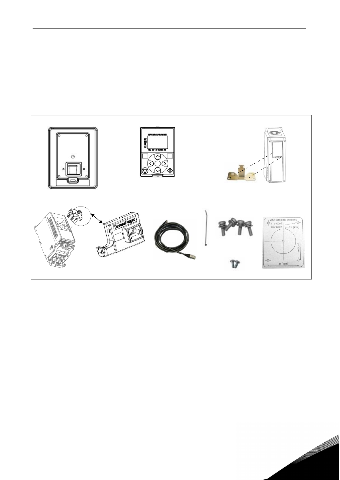
For the installation, you need the following parts (see picture below):
1. 2. 3a.
3b. 4. 5. 6. 8.
Compact drive
Figure 1. Door mounting kit parts
1. Control panel base
2. Cont rol Panel (standard drive kit do not include any panel, user order control panel with graphical
disp lay or text display separately. compact drive Kit include control panel with text display )
3a. Cable support (only available for standard drive)
3b. Adapter (only available for compact drive)
4. Data cable with attached grounding cabl e
5. Cable tie (Standard drive x2; Compact drive x 1)
6. Screws (M4X16 4 pcs)
7. Screws (PT3.5X8 2 pcs, only available for standard drive)
8. Mounting template
Standard drive
NOTE:
1) Should use the Text panel (2.) built after the B.ID 130420 (20th Apr 2013).
2) When us ed with Standard drive HV AC and Compact drive the LED in the door mounting kit is always
off since Item 1 (door panel base) B.ID 130905(5th Sep 2013) serial number S00000252299.
3) When with Standard drive series others than HVAC, make sure use it after B.ID 131120 (20th Nov
2013). If used with older boards the LED does not change according to the run, stop, alarm and fault
states of the drive.
4) MAKE SURE THAT YOU HAVE RECEIVED ALL NECESSARY PARTS!
.
Page 2
2 DPD01169F
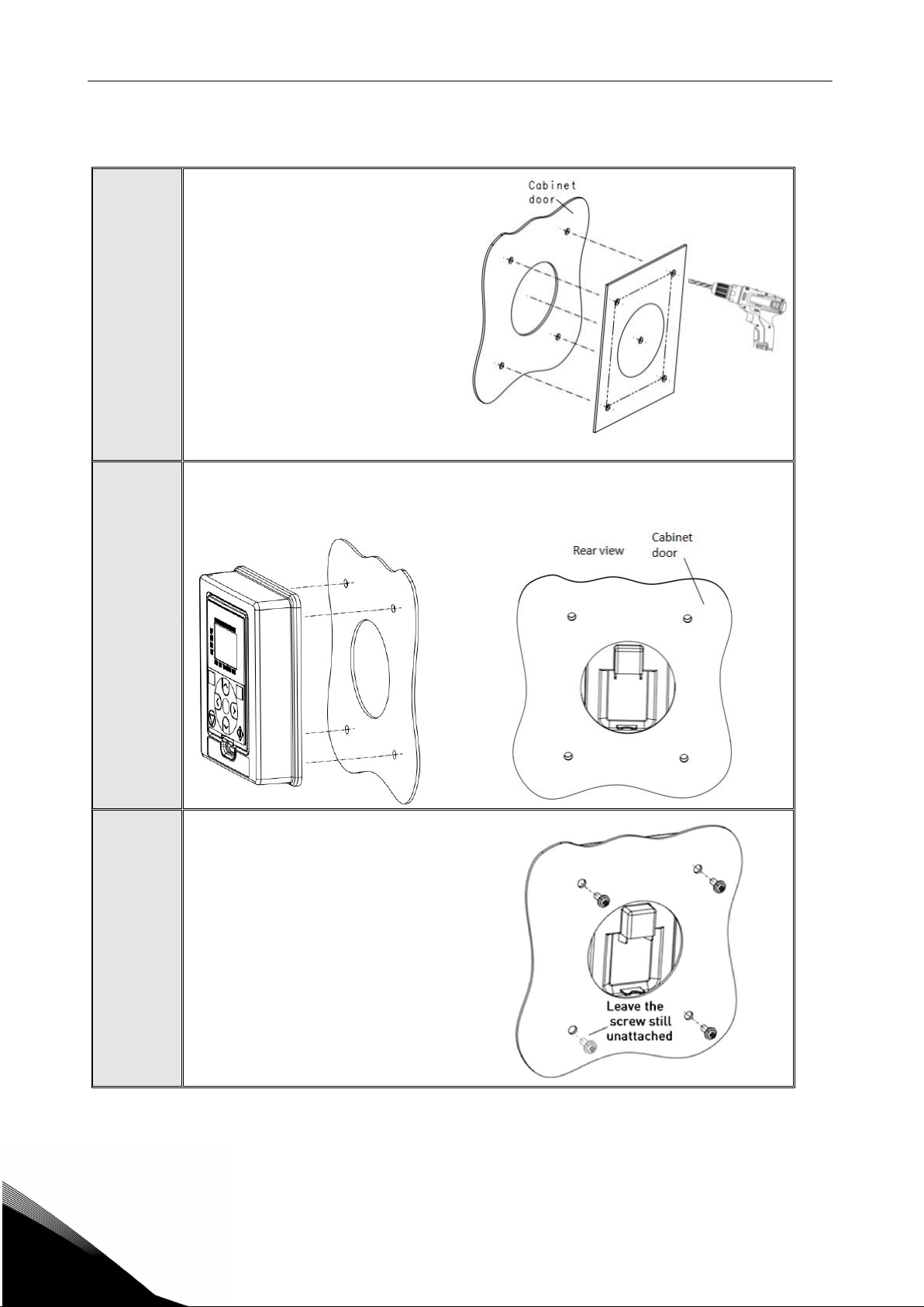
2. MOUNTING PROCEDURE
Place the mounting template (7.) on
the door or wall.
Make a hole exactly the same size as
the template for installation of the
1
door panel base (1.).
Remove the mounting template (7.)
from the door or wall.
Place the Door panel base (1.) toward the opening so that the screw holes you made in
the cabinet door meet the bushings on the backside of the base.
See figures bel ow.
2
3
Fix the base on the cabinet door by
tightening the screws (5.).
1.2
Page 3

DPD01169G 3
Fix the grounding cable (4.) against the
backside of the cabinet door through one
of the screw holes. Then use Cable tie (5)
insert into the hole as dot line indicated at
back of Door panel base (1) to tie cable.
NOTE: Ensure that a proper contact with
the cabinet door is achieved.
Remove the paint from the metal
surface if necessary.
Don't forget to place the washers
4
(attached to t he screws) between
the door and the screws. The
tightening torque is 1.5 Nm.
Connect the data cable (4.) to the
terminal of t he panel.
Do not connect Inverter and Motor’s PE wire together with Door pane l’s grounding cable.
5a
Attach the cable support in the control panel base
of the AC drive using the screw(7.)
(Only for standard drive)
.
Page 4

4 DPD01169F
Connect the other end of the data cable to the terminal in
the panel base of the AC drive.
Then use Cable tie (5) to tie cable to the cut of metal part
Ca ble sup port (only avai lable for s tandard drive)
5a
5b
6
Only for s tandard dr ive
Ass em ble adaptor(3b.) to a cov er and U ART
connector.
Connect cable(4.) to adaptor(3b.).
Only for compact drive
Assembly text display (2.) to Control panel
base (1.).
1.2
Page 5

 Loading...