

Page 1

MAKING MODERN LIVING POSSIBLE
Fitters Notes
Hints and tips for the installer
REFRIGERATION &
AIR CONDITIONING DIVISION
Manual
Page 2
This Fitters Notes, gives practical hints about Danfoss commercial
refrigeration controls (mechanical) and Danfoss compressors.
If you need further information about the Danfoss product range please
contact your dealer or local Danfoss agency. You can also find some very
useful information on our web site:
www.danfoss.com
We hope that this book will help you in your daily work.
Danfoss A/S
Page 3
Fitters notes
Chapter 1 . . . . . . . . . . . . . . . . . . Thermostatic expansion valves . . . . . . . . . . . . . . . . . . . . . . . . . . .page 3
Chapter 2 . . . . . . . . . . . . . . . . . . Solenoid valves . . . . . . . . . . . . . . . . . . . . . . . . . . . . . . . . . . . . . . . . . .page 13
Chapter 3 . . . . . . . . . . . . . . . . . . Pressure controls . . . . . . . . . . . . . . . . . . . . . . . . . . . . . . . . . . . . . . . .page 19
Chapter 4 . . . . . . . . . . . . . . . . . . Thermostats . . . . . . . . . . . . . . . . . . . . . . . . . . . . . . . . . . . . . . . . . . . . .page 27
expansion valves Solenoid valves Pressure controls Thermostats
Thermostatic
Chapter 5 . . . . . . . . . . . . . . . . . . Pressure regulators . . . . . . . . . . . . . . . . . . . . . . . . . . . . . . . . . . . . . .page 35
Chapter 6 . . . . . . . . . . . . . . . . . . Water valves . . . . . . . . . . . . . . . . . . . . . . . . . . . . . . . . . . . . . . . . . . . . .page 45
Chapter 7 . . . . . . . . . . . . . . . . . . Filter driers & sight glasses . . . . . . . . . . . . . . . . . . . . . . . . . . . . . .page 51
Chapter 8 . . . . . . . . . . . . . . . . . . Danfoss compressors. . . . . . . . . . . . . . . . . . . . . . . . . . . . . . . . . . . . .page 61
regulators Water valves
Pressure
Filter driers &
sight glasses
compressors Practical tips Trouble shooting
Danfoss
Chapter 9 . . . . . . . . . . . . . . . . . . Practical tips . . . . . . . . . . . . . . . . . . . . . . . . . . . . . . . . . . . . . . . . . . . page 125
Chapter 10 . . . . . . . . . . . . . . . . . Trouble shooting . . . . . . . . . . . . . . . . . . . . . . . . . . . . . . . . . . . . . . page 145
© Danfoss A/S (AC-DSL/MWA), 10 - 2006 DKRCC.PF.000.G1.02 / 520H1459 1
Page 4

Page 5

Fitters notes Thermostatic expansion valves
Contents Page
Introduction. . . . . . . . . . . . . . . . . . . . . . . . . . . . . . . . . . . . . . . . . . . . . . . . . . . . . . . . . . . . . . . . . . . . . . . . . . . . . . . . . . . . . . . .5
Superheat . . . . . . . . . . . . . . . . . . . . . . . . . . . . . . . . . . . . . . . . . . . . . . . . . . . . . . . . . . . . . . . . . . . . . . . . . . . . . . . . . . . . . . . . . .5
Subcooling . . . . . . . . . . . . . . . . . . . . . . . . . . . . . . . . . . . . . . . . . . . . . . . . . . . . . . . . . . . . . . . . . . . . . . . . . . . . . . . . . . . . . . . . .5
External pressure equalization . . . . . . . . . . . . . . . . . . . . . . . . . . . . . . . . . . . . . . . . . . . . . . . . . . . . . . . . . . . . . . . . . . . . . .6
Charges . . . . . . . . . . . . . . . . . . . . . . . . . . . . . . . . . . . . . . . . . . . . . . . . . . . . . . . . . . . . . . . . . . . . . . . . . . . . . . . . . . . . . . . . . . . .6
Universal charge . . . . . . . . . . . . . . . . . . . . . . . . . . . . . . . . . . . . . . . . . . . . . . . . . . . . . . . . . . . . . . . . . . . . . . . . . . . . . . . .6
MOP charge . . . . . . . . . . . . . . . . . . . . . . . . . . . . . . . . . . . . . . . . . . . . . . . . . . . . . . . . . . . . . . . . . . . . . . . . . . . . . . . . . . . .6
MOP ballast charge . . . . . . . . . . . . . . . . . . . . . . . . . . . . . . . . . . . . . . . . . . . . . . . . . . . . . . . . . . . . . . . . . . . . . . . . . . . . .7
Thermostatic expansion valve selection . . . . . . . . . . . . . . . . . . . . . . . . . . . . . . . . . . . . . . . . . . . . . . . . . . . . . . . . . . . . .7
Identification . . . . . . . . . . . . . . . . . . . . . . . . . . . . . . . . . . . . . . . . . . . . . . . . . . . . . . . . . . . . . . . . . . . . . . . . . . . . . . . . . . . . . . .7
Installation . . . . . . . . . . . . . . . . . . . . . . . . . . . . . . . . . . . . . . . . . . . . . . . . . . . . . . . . . . . . . . . . . . . . . . . . . . . . . . . . . . . . . . . . .8
Setting . . . . . . . . . . . . . . . . . . . . . . . . . . . . . . . . . . . . . . . . . . . . . . . . . . . . . . . . . . . . . . . . . . . . . . . . . . . . . . . . . . . . . . . . . . . . .9
Orifice assembly replacement. . . . . . . . . . . . . . . . . . . . . . . . . . . . . . . . . . . . . . . . . . . . . . . . . . . . . . . . . . . . . . . . . . . . . 10
Danfoss product range. . . . . . . . . . . . . . . . . . . . . . . . . . . . . . . . . . . . . . . . . . . . . . . . . . . . . . . . . . . . . . . . . . . . . . . . . . . . 11
expansion valves
Thermostatic
© Danfoss A/S (AC-DSL/MWA), 10 - 2006 DKRCC.PF.000.G1.02 / 520H1459 3
Page 6

Notes
4 DKRCC.PF.000.G1.02 / 520H1459 © Danfoss A/S (AC-DSL/MWA), 10 - 2006
Page 7
Fitters notes Thermostatic expansion valves
© Danfoss A/S (AC-DSL/MWA), 10 - 2006 DKRCC.PF.000.G1.02 / 520H1459 5
Thermostatic
expansion valves
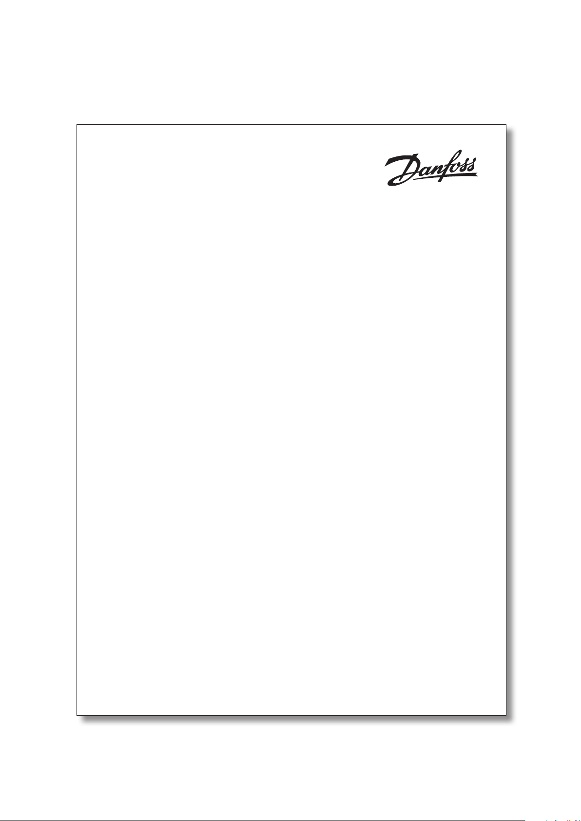
A thermostatic expansion valve is built up around
a thermostatic element (1) separated from the
valve body by a diaphragm.
A capillary tube connects the element to a bulb
(2) and a valve body with valve seat (3) and a
spring (4).
A thermostatic expansion valve works like this:
The function of a thermostatic expansion valve is
determined by three fundamental pressures:
P1: Bulb pressure which acts on the upper
surface of the diaphragm, in the valve
opening direction.
P2: Evaporating pressure which acts on the
underside of the diaphragm, in the valve
closing direction.
P3: Spring pressure which also acts on the
underside of the diaphragm, in the valve
closing direction.
When the expansion valve regulates, balance is
created between bulb pressure on one side of the
diaphragm and evaporating pressure plus spring
force on the other side.
The spring is used to set superheat.
Ad0-0001
Introduction
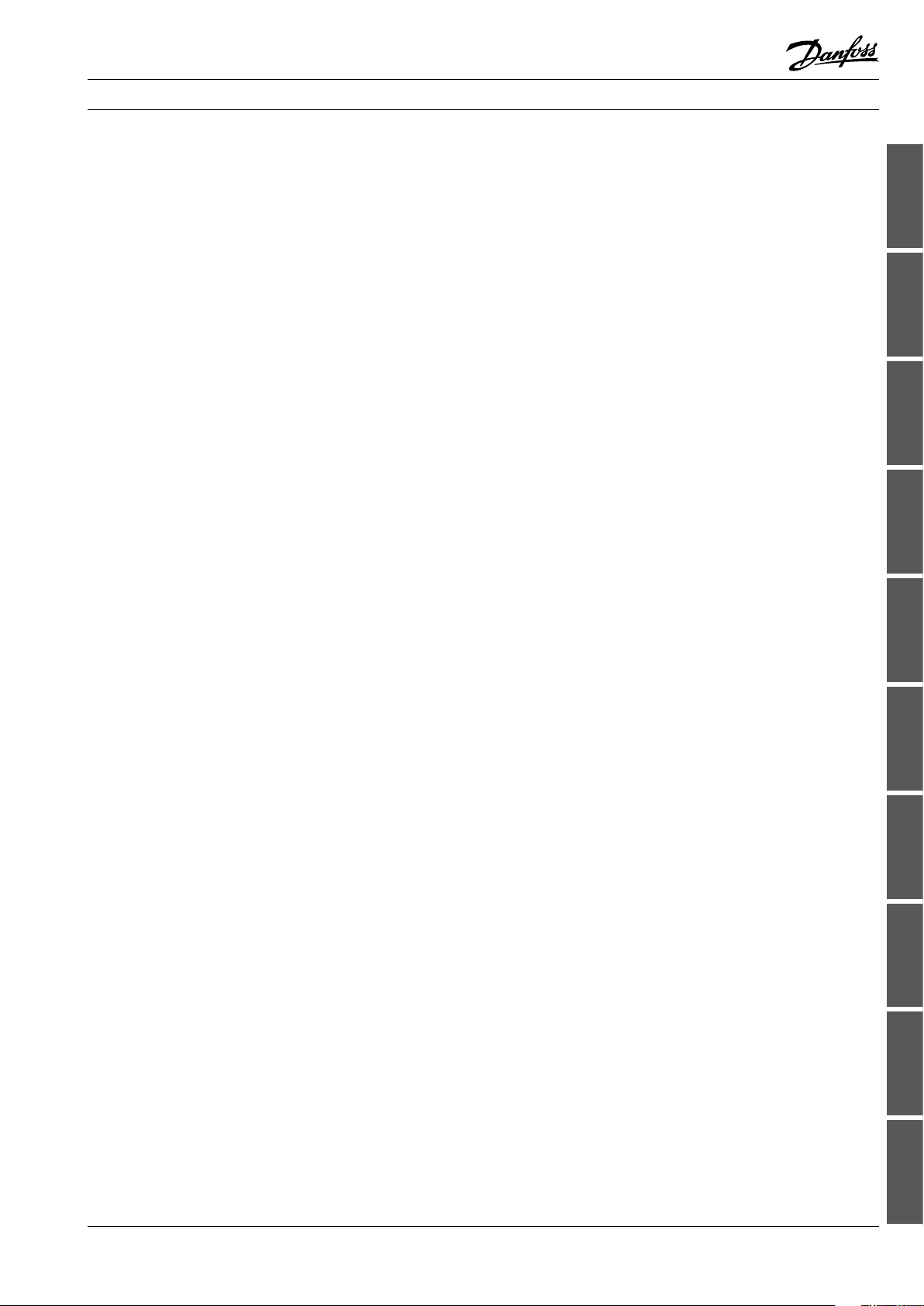
Superheat is measured at the point where the
bulb is located on the suction line and is the
diff erence between the temperature at the
bulb and the evaporating pressure/evaporating
temperature at the same point.
Superheat is measured in Kelvin (K) and is used as
a signal to regulate liquid injection through the
expansion valve.
Ad0-0012
Ad0-0015
Superheat
Subcooling Subcooling is defi ned as the diff erence between
condensing pressure/temperature and liquid
temperature at the expansion valve inlet.
Subcooling is measured in Kelvin (K).
Subcooling of the refrigerant is necessary to
avoid vapour bubbles in the refrigerant ahead of
the expansion valve.
Vapour bubbles in the refrigerant reduce capacity
in the expansion valve and thereby reduce liquid
supply to the evaporator.
Subcooling of 4-5K is adequate in most cases.
Page 8
Fitters notes Thermostatic expansion valves
External pressure equalization
Expansion valves with external pressure equalization must always be used if liquid distributors
are installed.
Typically, the use of distributors gives a pressure
drop of 1 bar across distributor and distribution
tubes.
Expansion valves with external pressure equalization should always be used in refrigeration
systems with heavy evaporators or plate
exchangers, where normally the pressure drop
will be greater than pressure corresponding to
2K.
Charges Thermostatic expansion valves can contain one
of three different types of charge:
1. Universal charge
2. MOP charge
3. MOP charge with ballast, standard for Danfoss
expansion valves with MOP.
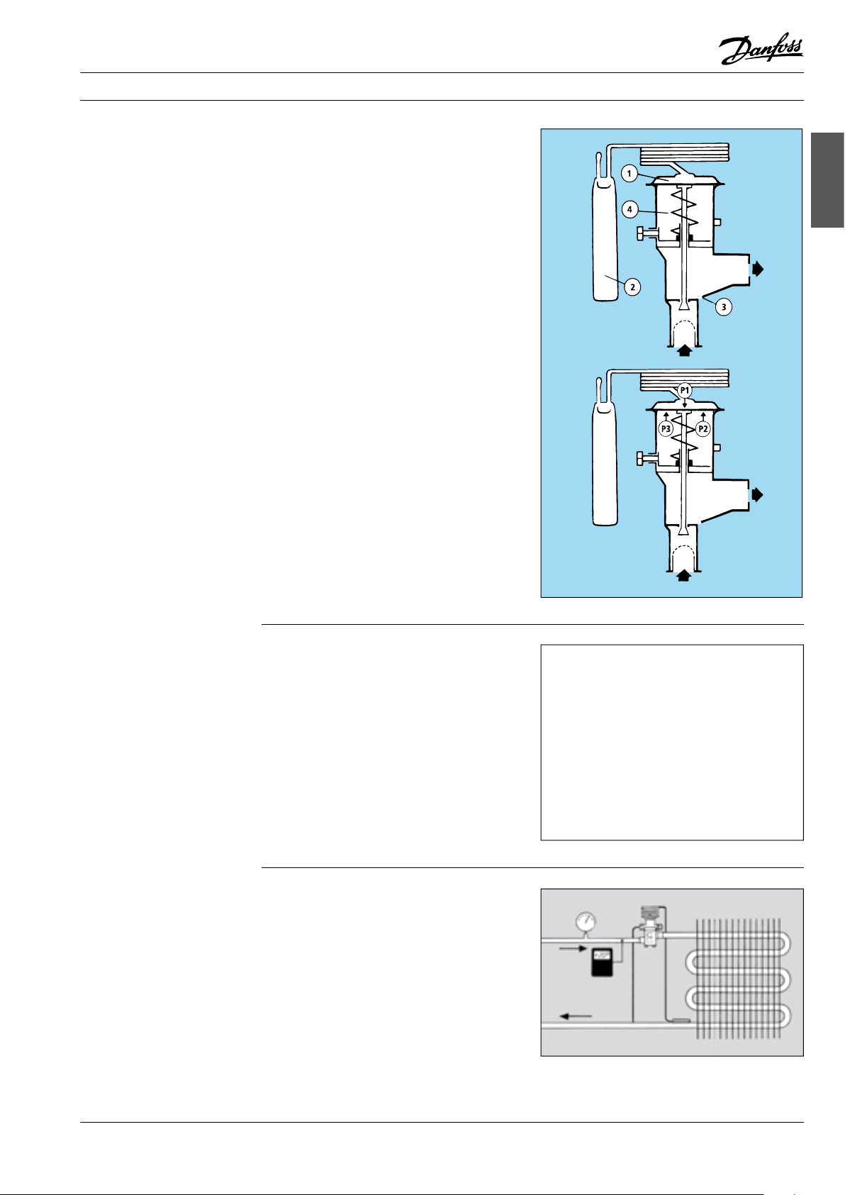
Universal charge
Expansion valves with Universal charge are used
in most refrigeration systems where there is no
pressure limitation requirement and where the
bulb can be located warmer than the element
or at high evaporating temperature/evaporating
pressure.
Ad0-0016
MOP charge
Universal charge means that there is liquid
charge in the bulb. The amount of charge is so
large that charge remains in the bulb irrespective
of whether the element is colder or warmer than
the bulb.
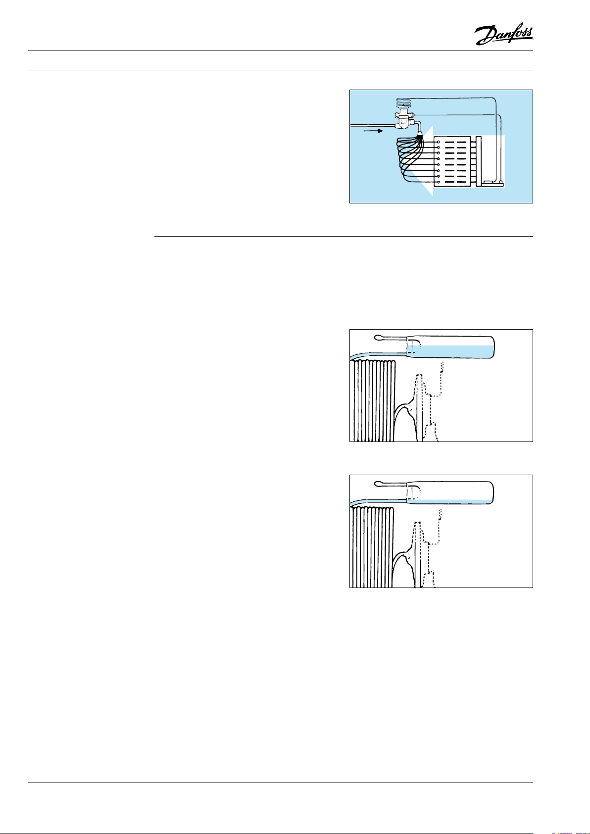
Expansion valves with MOP charge are typically
used on factory-made units where suction
pressure limitation on starting is required, e.g.
in the transport sector and in air conditioning
systems.
All expansion valves with MOP have a very small
charge in the bulb.
This means that the valve or the element must be
located warmer than the bulb. If it is not, charge
can migrate from the bulb to the element and
prevent the expansion valve from functioning.
MOP charge means limited liquid charge in the
bulb.
“MOP” stands for Maximum Operating Pressure
and is the highest suction pressure/ evaporating
pressure permissible in the evaporator/suction
line.
The charge will have evaporated when the
temperature reaches the MOP point. Gradually,
as the suction pressure rises, the expansion valve
begins to close at approx. 0.3/0.4 bar below the
MOP point. It becomes completely closed when
the suction pressure is the same as the MOP
point.
Ad0-0017
Ad0-0018
MOP is often called “Motor Overload Protection”.
6 DKRCC.PF.000.G1.02 / 520H1459 © Danfoss A/S (AC-DSL/MWA), 10 - 2006
Page 9
Fitters notes Thermostatic expansion valves
MOP ballast charge
Thermostatic expansion valve selection
Expansion valves with MOP ballast charges are
used mainly in refrigeration systems with “highdynamic” evaporators, e.g. in air conditioning
systems and plate heat exchangers with high
heat transfer.
With MOP ballast charge, up to 2 - 4 K less
superheat can be obtained than with other types
of charge.
The bulb in a thermostatic expansion valve
contains a material of high porosity and large
surface area in relation to weight.
MOP charge with ballast has a damping effect on
expansion valve regulation.
The valve opens slowly as bulb temperature rises
and closes quickly as bulb temperature fails.
The thermostatic expansion valve can be selected when the following are known:
Refrigerant
Evaporator capacity
Evaporating pressure
Condensing pressure
Ad0-0021
Subcooling
Pressure drop across valve
Internal or external pressure equalization
expansion valves
Thermostatic
Identification The thermostatic element is fitted with a laser
engraving on top of the diaphragm.
The code refers to the refrigerant for which the
valve is designed:
L = R410A
N = R134a
S = R404A/ R507
X = R22
Z = R407C
This engraving gives valve type (with code
number), evaporating temperature range, MOP
point, refrigerant, and max. working pressure,
PS/MWP.
With TE 20 and TE 55 the rated capacity is
stamped on a band label fastened to the valve.
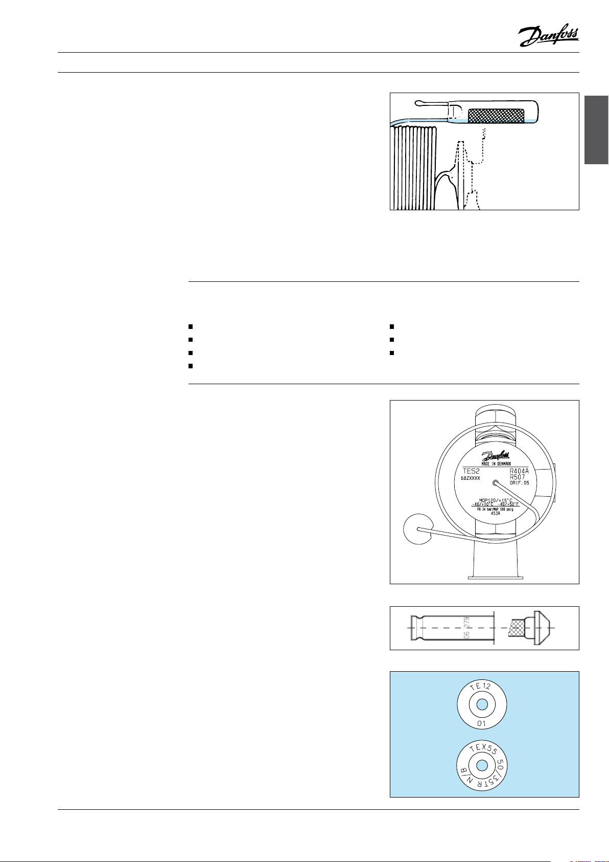
The orifice assembly for T2 and TE2 is marked
with the orifice size (e.g. 06) and week stamp +
last number in the year (e.g. 279).
The orifice assembly number is also given on the
lid of its plastic container.
On TE 5 and TE 12 the upper stamp (TE 12)
indicates for which valve type the orifice can be
used. The lower stamp (01) is the orifice size.
On TE 20 and TE 55 the lower stamp (50/35 TR
N/B) indicates the rated capacity in the two
evaporating temperature ranges N and B, and the
refrigerant. (50/35 TR = 175 kW in range N and
123 kW in range B).
The upper stamp (TEX 55) refers to the valve type
for which the assembly can be used.
Ad0-0019
Ad0-0023
Ad0-0020
© Danfoss A/S (AC-DSL/MWA), 10 - 2006 DKRCC.PF.000.G1.02 / 520H1459 7
Page 10
Fitters notes Thermostatic expansion valves
8 DKRCC.PF.000.G1.02 / 520H1459 © Danfoss A/S (AC-DSL/MWA), 10 - 2006
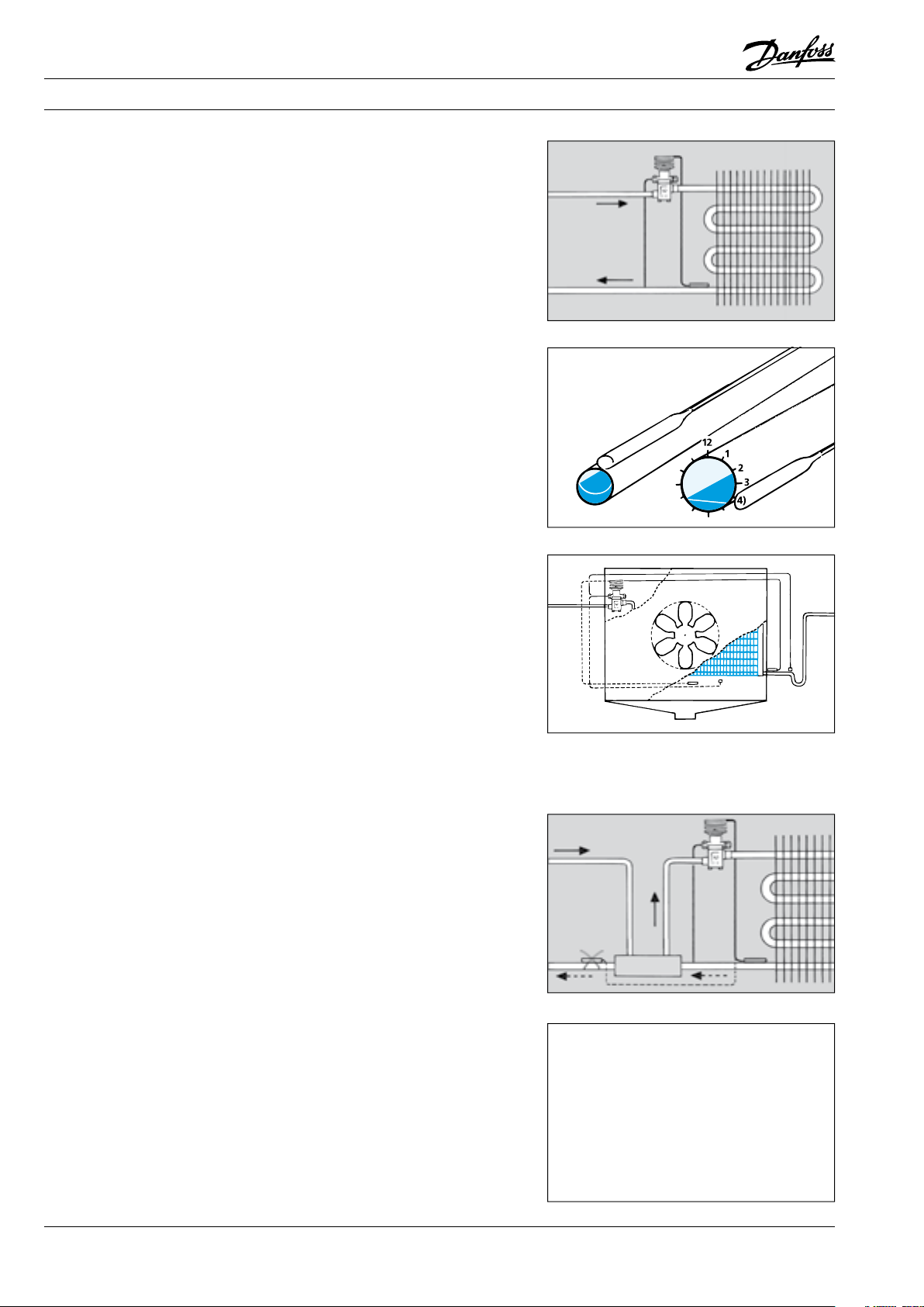
The bulb is best mounted on a horizontal suction
line tube and in a position corresponding to
between 1 o’clock and 4 o’clock.
Location depends on the outside diameter of the
tube.
Note:
The bulb must never be located at the bottom
of the suction line due to the possibility of oil
laying in the bottom of the pipe causing false
signals.
Ad0-0002
Ad0-0003
Installation The expansion valve must be installed in the
liquid line, ahead of the evaporator, with its
bulb fastened to the suction line as close to the
evaporator as possible.
If there is external pressure equalization, the
equalizing line must be connected to the suction
line immediately after the bulb.
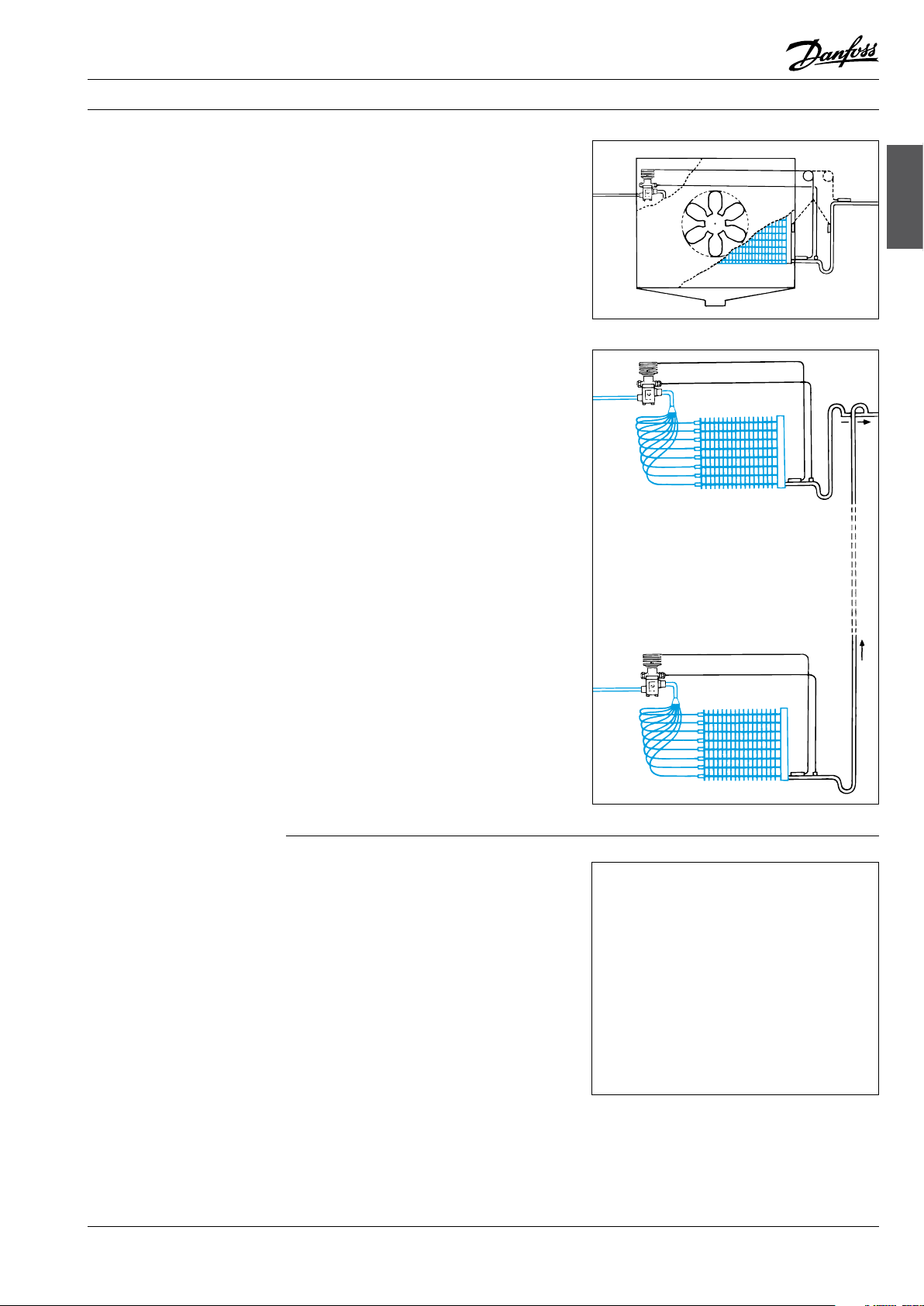
The bulb must not be installed after a heat
exchanger because in this position it will give
false signals to the expansion valve.
The bulb must not be installed close to components of large mass as this also will give rise to
false signals to the expansion valve
Ad0-0004
Ad0-0005
Ad0-0006
The bulb must be able to sense the tem pe ra tu re
of the superheated suction vapour and must
therefore not be located in a position that will
expose it to extraneous heat/cold.
If the bulb is exposed to a warm air current,
insulation of the bulb is recommended.
The Danfoss bulb strap allows a tight and secure
fi tting of the bulb to the tube, thereby securing
that the bulb has ultimate thermal contact to
the suction tube. The TORX design of the screw
makes it easy for the fi tter to transfer the torque
from the tool to the screw without having to
press the tool into the screw slot. Furthermore,
with the TORX slot design, there is no risk of
damaging the screw slot.
Page 11
Fitters notes Thermostatic expansion valves
Installation (cont.)
As previously mentioned, the bulb must be
installed to the horizontal part of the suction line
immediately after the evaporator. It must not be
installed to a collection tube or a riser after an oil
pocket.
The expansion valve bulb must always be
installed ahead of any liquid lock.
Ad0-0007
expansion valves
Thermostatic
Ad0-0008
Setting The expansion valve is supplied with a factory
setting suitable for most applications.
If necessary, readjustment can be made using the
setting spindle on the valve.
Turning the spindle clockwise increases the
expansion valve superheat and turning it
counterclock-wise reduces it.
For T /TE 2, one turn of the spindle produces a
change of approx. 4K in the superheat at 0°C
evaporating temperature.
Ad0-0009
© Danfoss A/S (AC-DSL/MWA), 10 - 2006 DKRCC.PF.000.G1.02 / 520H1459 9
Page 12
Fitters notes Thermostatic expansion valves
Setting (cont.)
For TE 5 and following sizes, one turn of the
spindle produces a change of approx. 0.5K in
the superheat at 0°C evaporating temperature.
For TUA and TUB, one turn of the spindle
produces a change of approx. 3K in the superheat at 0°C evaporating temperature.
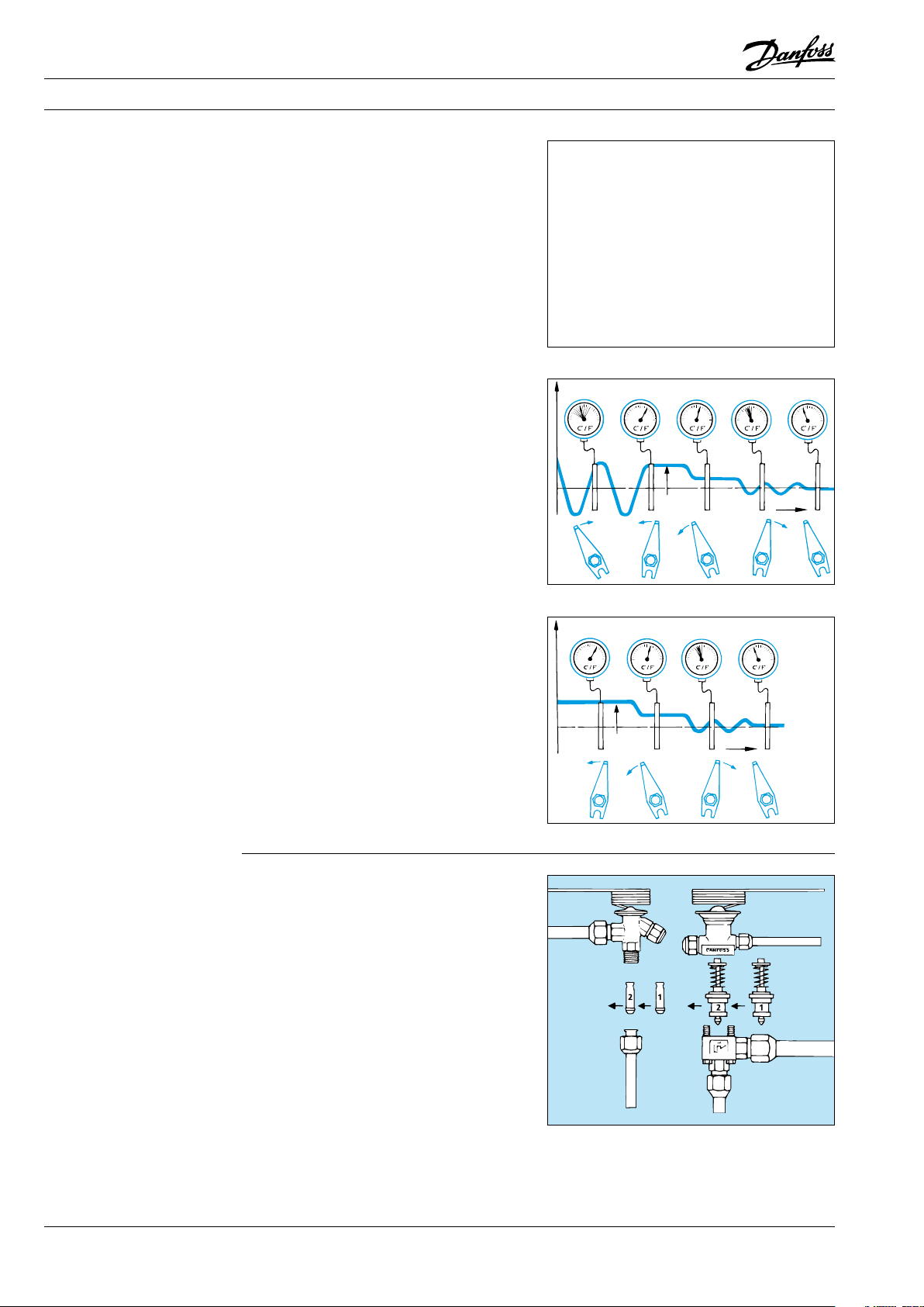
Hunting in the evaporator can be eliminated by
the following procedure:
Increase the superheat by turning the expansion
valve setting spindle well to the right (clockwise)
so that hunting stops. Then turn the setting
spindle in counter-clockwise steps so that
hunting again occurs.
From this position, turn the spindle about once
clockwise (but only 1/4 turn for T /TE 2 valves).
On this setting the refrigeration system will not
hunt and the evaporator is fully utilized.
A variation of 1 K in superheat is not regarded as
hunting.
Ad0-0010
Ad0-0011
Orifice assembly
replacement
If the superheat in the evaporator is too high, the
reason might be an inadequate supply of liquid
refrigerant.
The superheat can be reduced by turning the
expansion valve setting spindle counterclockwise
in steps until hunting is observed.
From this setting, the spindle must be turned
about once clockwise (but only 1/4 turn for T/TE
2). This setting fully utilizes the evaporator.
A variation of 1 K in superheat is not regarded as
hunting.
Ad0-0013
If the evaporator continues to hunt, regardless of
the superheat setting, the valve capacity might
be too high and the orifice assembly, or the valve,
needs replacing with a smaller one.
If the evaporator superheat is too high the valve
capacity is too low and the orifice assembly must
be replaced with a larger one.
TE, T2, TUA, TCAE valves are supplied with an
interchangeable orifice.
Ad0-0014
10 DKRCC.PF.000.G1.02 / 520H1459 © Danfoss A/S (AC-DSL/MWA), 10 - 2006
Page 13
Fitters notes Thermostatic expansion valves
Danfoss product range
Thermostatic expansion
valves
Danfoss offers a comprehensive range of
thermostatic expansion valves with capacities
from 0.4 to 1083 kW (R134a).
T/TE 2 valves have a brass housing and flare/
flare or solder/flare connections.
Rated capacity: 0.4 - 10.5 kW (R134a).
TUA, TUB, TUC valves have a stainless steel
housing and stainless steel/copper bimetal
solder connections.
Rated capacity: 0.5 - 12 kW (R134a).
The valves can be supplied with or without
external pressure equalization.
TUA has an interchangeable orifice
assembly and adjustable superheat.
TUB has a fixed orifice and adjustable
superheat.
TUC has a fixed orifice and factory set
superheat.
TUB and TUC are primarily for OEM customers.
All TUB and TUC valves can be replaced by TUA
valves.
TCAE, TCBE, TCCE valves have a stainless steel
housing and stainless steel/copper bimetal
solder connections.
Rated capacity: 12 - 18 kW (R134a).
The valves are designed as the TU valves but with
a higher capacity.
TDE valves have a brass housing and copper
solder connections.
Rated capacity: 10.5 - 140 kW (R407C)
The valves are supplied with a fixed orifice and
adjustable superheat.
TE 5 - TE 55 valves have a brass housing.
The valves are supplied as a part programme
consisting of valve housing, orifice and thermostatic element.
The valve housing is available in a straightway
or angleway version with solder, flare and flange
connections.
Rated capacity: 12.9 - 220 kW (R134a).
The valves are supplied with external pressure
equalization.
PHT 85 - 300 valves are supplied as a part
programme consisting of valve housing, flanges,
orifice and thermostatic element.
Rated capacity: 55 - 1083 kW (R134a).
For further information consult the internet or
the catalogue material.
expansion valves
Thermostatic
The valves are supplied with external pressure
equalization.
TRE valves have a brass housing and stainless
steel/copper bimetal connections.
Rated capacity: 18 - 196 kW (R134a).
The valves are supplied with a fixed orifice and
adjustable superheat.
© Danfoss A/S (AC-DSL/MWA), 10 - 2006 DKRCC.PF.000.G1.02 / 520H1459 11
Page 14

Page 15

Fitters notes Solenoid valves
Contents Page
Installation . . . . . . . . . . . . . . . . . . . . . . . . . . . . . . . . . . . . . . . . . . . . . . . . . . . . . . . . . . . . . . . . . . . . . . . . . . . . . . . . . . . . . . . 15
EVRA 32 & 40 precautions . . . . . . . . . . . . . . . . . . . . . . . . . . . . . . . . . . . . . . . . . . . . . . . . . . . . . . . . . . . . . . . . . . . . . 15
When pressure testing . . . . . . . . . . . . . . . . . . . . . . . . . . . . . . . . . . . . . . . . . . . . . . . . . . . . . . . . . . . . . . . . . . . . . . . . 16
The coil. . . . . . . . . . . . . . . . . . . . . . . . . . . . . . . . . . . . . . . . . . . . . . . . . . . . . . . . . . . . . . . . . . . . . . . . . . . . . . . . . . . . . . . . . . . 17
The correct product. . . . . . . . . . . . . . . . . . . . . . . . . . . . . . . . . . . . . . . . . . . . . . . . . . . . . . . . . . . . . . . . . . . . . . . . . . . . . . . 18
Solenoid valves
© Danfoss A/S (AC-DSL/MWA), 10 - 2006 DKRCC.PF.000.G1.02 / 520H1459 13
Page 16

Notes
14 DKRCC.PF.000.G1.02 / 520H1459 © Danfoss A/S (AC-DSL/MWA), 10 - 2006
Page 17
Fitters notes Solenoid valves
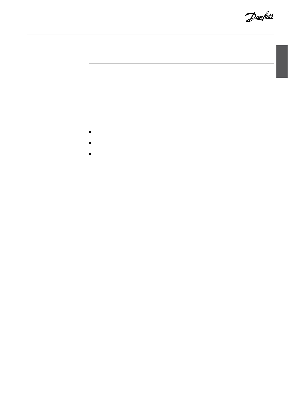
Installation
All EVR/EVRA, and EVH types solenoid valves
operate only when installed correctly in the
direction of flow, i.e. in the direction indicated by
the arrow.
Normally, solenoid valves installed ahead of a
thermostatic expansion valve must be close to
that valve.
This avoids liquid hammer when the solenoid
valve opens.
Ensure that pipes around the valve are properly
installed so that no fracture can occur.
Solenoid valves
Af0_0001
Af0_0003
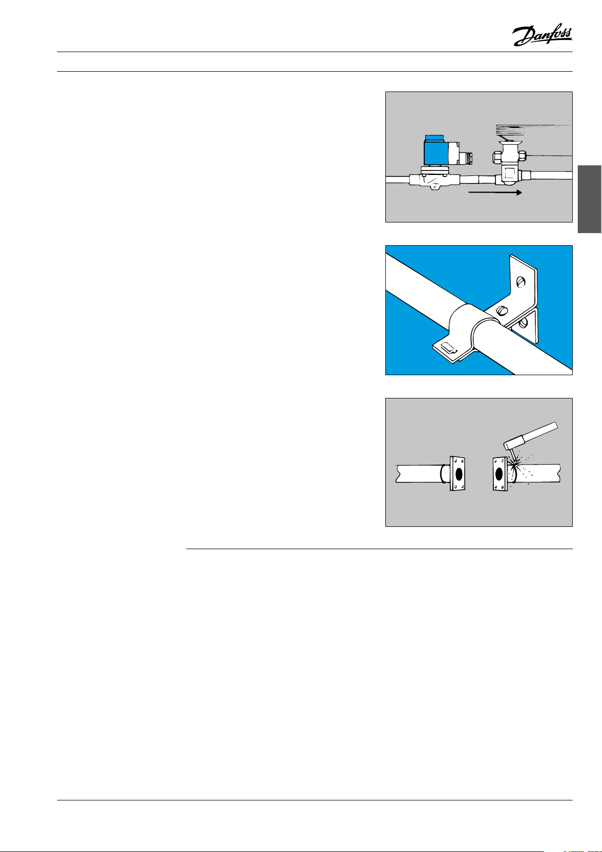
EVRA 32 & 40 precautions
Brazing/welding EVR/EVRA and EVH solenoid
valves does not normally necessitate dismantling,
provided steps are taken to avoid heating the
valve.
Note! Always protect the armature tube against
weld spatter.
After tacking the valve to the pipe, remove the
valve body to protect O-rings and gaskets against
heat. In installations with welded steel pipe, a
FA type strainer or similar mounted ahead of the
solenoid valve is recommended. (On new plant,
flushing out before starting up is recommended).
Af0_0004
© Danfoss A/S (AC-DSL/MWA), 10 - 2006 DKRCC.PF.000.G1.02 / 520H1459 15
Page 18
Fitters notes Solenoid valves
16 DKRCC.PF.000.G1.02 / 520H1459 © Danfoss A/S (AC-DSL/MWA), 10 - 2006
Af0_0005
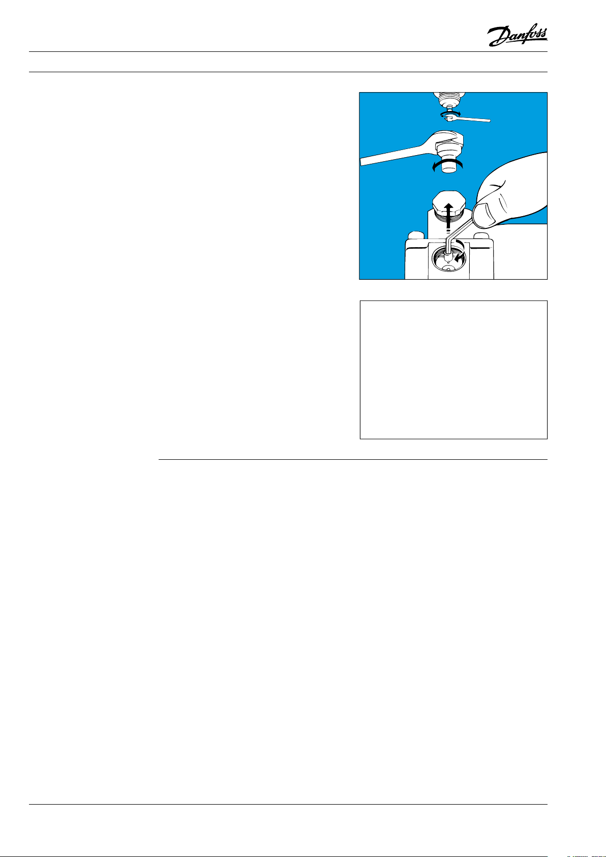
All solenoid valves in the system must be open,
either by applying voltage to the coils or by
opening the valves manually (provided a manual
operation spindle is fi tted).
Remember to screw the spindle back before
starting up, otherwise the valve will be unable to
close.
When pressure testing
Always use counter force when fi nally
tightening the solenoid valve on pipes, i.e.
two spanners on the same side of the valve.
Af0_0006
Page 19
Fitters notes Solenoid valves
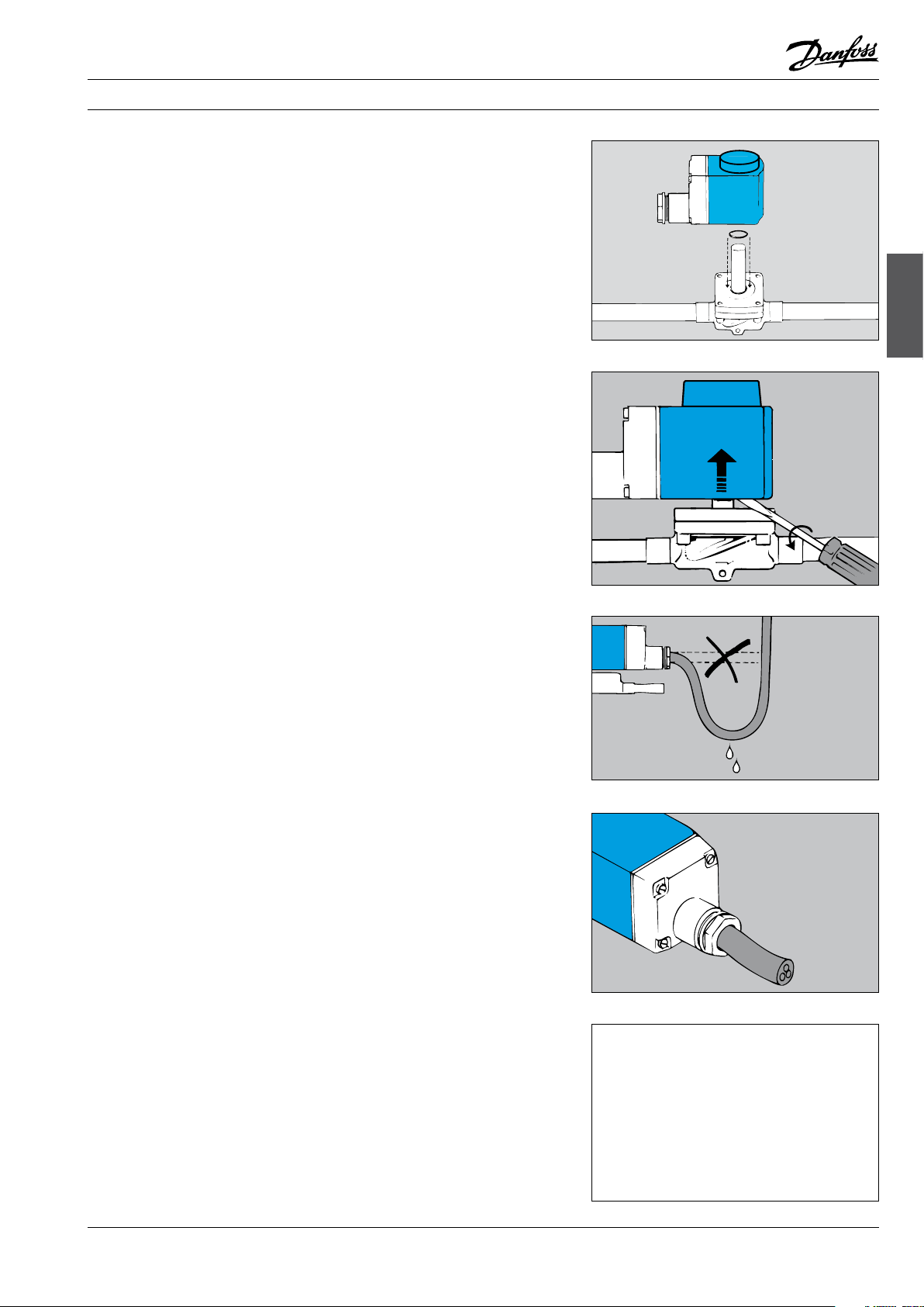
The coil
When fitting the coil, it has merely to be pressed
down over the armature tube until a click is
heard. This means that the coil has been correctly
fitted.
Note: Remember to fit an O-ring between valve
body and coil.
Be sure that the O-ring is smooth, not damaged
and that the surface is free from paint or any
other material.
Note: The O-ring must be changed at service.
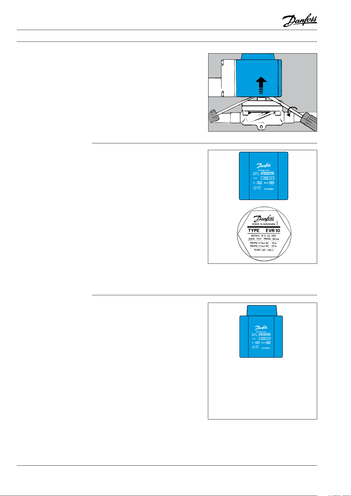
The coil can be removed by inserting a
screwdriver between valve body and coil. The
screwdriver can then be used as a lever to loosen
the coil.
Solenoid valves
Af0_0018
Af0_0019
Be careful with cable entries. It must not be
possible for water to enter the terminal box. The
cable must be led out via a drip loop.
The entire cable circumference must be retained by the cable entry.
Therefore, always use round cable (which is the
only type of cable that can be sealed effectively).
Be aware of the colour of leads in the cable.
Yellow/green is always earth.
Leads of one colour are either phase or neutral.
Af0_0009
Af0_0010
Af0_0011
© Danfoss A/S (AC-DSL/MWA), 10 - 2006 DKRCC.PF.000.G1.02 / 520H1459 17
Page 20
Fitters notes Solenoid valves
The coil (cont.)
The correct product
(The “old” coil type)
When removing a coil it might be necessary to
use hand tools, e.g. two screwdrivers.
Make sure that coil data (voltage and frequency)
and supply voltage correspond. If they do not,
the coil might burn out. Always ensure that valve
and coil match each other.
When replacing a coil in an EVR 20 NC
(NC = normally closed) note:
- A valve body using an a.c. coil has a square
armature.
- A valve body using a d.c. coil has a round
armature.
Fitting the wrong coil results in a lower MOPD.
See data on the top nut. As far as possible, always
choose single-frequency coils. These give off
less heat than double-frequency coils.
Use NC (normally closed) solenoid valves for
systems in which the valve must remain closed
(de-energised) for most of the operating time.
Use NO (normally open) solenoid valves for
systems in which the valve must remain open
(de-energised) for most of the operating time.
Never replace an NO (normally open) solenoid
valve with an NC (normally closed) valve - or vice
versa.
Af0_0012
Af0_0013
Af0_0014
(The new “clip-on” coil type)
Two labels are supplied with each clip-on coil
(see illustration).
The adhesive label is for attaching to the side of
the coil, while the other, perforated label should
be placed over the armature tube before the coil
is clicked into position.
Af0_0015
Af0_0020
18 DKRCC.PF.000.G1.02 / 520H1459 © Danfoss A/S (AC-DSL/MWA), 10 - 2006
Page 21

Fitter notes Pressure controls
Contents Page
Installation . . . . . . . . . . . . . . . . . . . . . . . . . . . . . . . . . . . . . . . . . . . . . . . . . . . . . . . . . . . . . . . . . . . . . . . . . . . . . . . . . . . . . . . 21
Placing of surplus capillary tube. . . . . . . . . . . . . . . . . . . . . . . . . . . . . . . . . . . . . . . . . . . . . . . . . . . . . . . . . . . . . . . . . . . 22
Setting . . . . . . . . . . . . . . . . . . . . . . . . . . . . . . . . . . . . . . . . . . . . . . . . . . . . . . . . . . . . . . . . . . . . . . . . . . . . . . . . . . . . . . . . . . . 22
Low-pressure control. . . . . . . . . . . . . . . . . . . . . . . . . . . . . . . . . . . . . . . . . . . . . . . . . . . . . . . . . . . . . . . . . . . . . . . . . . 22
High-pressure control. . . . . . . . . . . . . . . . . . . . . . . . . . . . . . . . . . . . . . . . . . . . . . . . . . . . . . . . . . . . . . . . . . . . . . . . . 22
Example with four compressors in parallel (R404A). . . . . . . . . . . . . . . . . . . . . . . . . . . . . . . . . . . . . . . . . . . . . 23
Setting LP for outdoor location. . . . . . . . . . . . . . . . . . . . . . . . . . . . . . . . . . . . . . . . . . . . . . . . . . . . . . . . . . . . . . . . 23
Indicative evaporating pressures (pe) for different types of systems . . . . . . . . . . . . . . . . . . . . . . . . . . . . . . . . 23
Test of contact function . . . . . . . . . . . . . . . . . . . . . . . . . . . . . . . . . . . . . . . . . . . . . . . . . . . . . . . . . . . . . . . . . . . . . . . . . . . 24
The correct pressure control for your system. . . . . . . . . . . . . . . . . . . . . . . . . . . . . . . . . . . . . . . . . . . . . . . . . . . . . . . 25
Pressure controls
© Danfoss A/S (AC-DSL/MWA), 10 - 2006 DKRCC.PF.000.G1.02 / 520H1459 19
Page 22

Notes
20 DKRCC.PF.000.G1.02 / 520H1459 © Danfoss A/S (AC-DSL/MWA), 10 - 2006
Page 23
Fitter notes Pressure controls
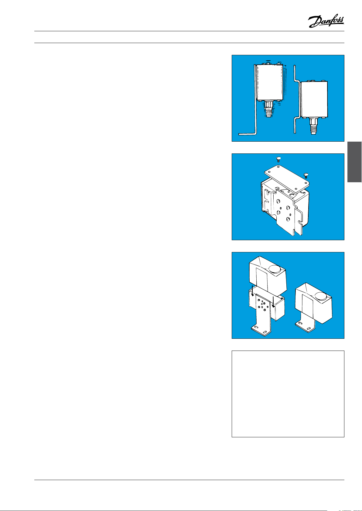
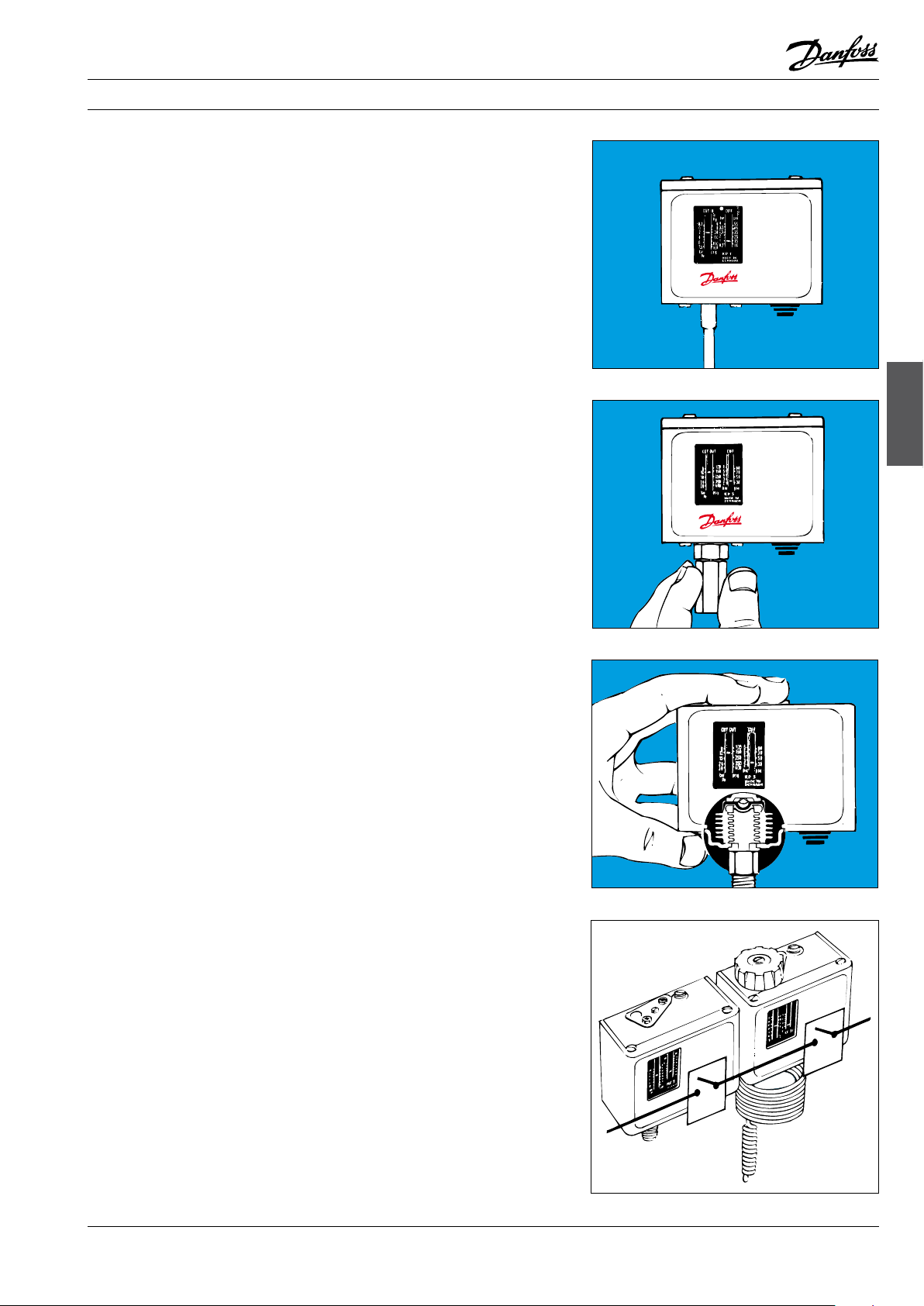
Installation
Mount the KP pressure control on a bracket or on
a completely flat surface.
The pressure control can also be mounted on the
compressor itself.
In unfavourable conditions, an angle bracket
could amplify vibration in the mounting plane.
Therefore, always use a wall bracket where strong
vibration occurs.
If the risk of water droplets or water spray is
present, the accompanying top plate should be
used. The plate increases the grade of enclosure
to IP 44 and is suitable for all KP pressure controls.
To obtain IP 44, the holes in the backplate of the
control must be covered by mounting on either
an angle bracket (060-105666) or a wall plate
(060-105566).
The top plate is supplied with all units incorporating automatic reset. It can also be used on
units with manual reset, but in that case must
be purchased separately (code no.: for single unit,
060-109766; for dual unit, 060-109866).
If the unit is to be used in dirty conditions or
where it might be exposed to heavy spray -
from above or from the side - it should be fitted
with a protective cap. The cap can be used
together with either an angle bracket or a wall
bracket.
Al0_0001
Al0_0007
Pressure controls
Al0_0008
If the unit risk being exposed to heavy water
influence a better grade of enclosure can be
achieved when mounting the product in a special
IP 55 enclosure.
The IP 55 enclosure is available for both single
unit (060-033066) and dual unit (060-035066).
Ak0_0020
© Danfoss A/S (AC-DSL/MWA), 10 - 2006 DKRCC.PF.000.G1.02 / 520H1459 21
Page 24
Fitter notes Pressure controls
Installation (cont.)
Placing of surplus
capillary tube
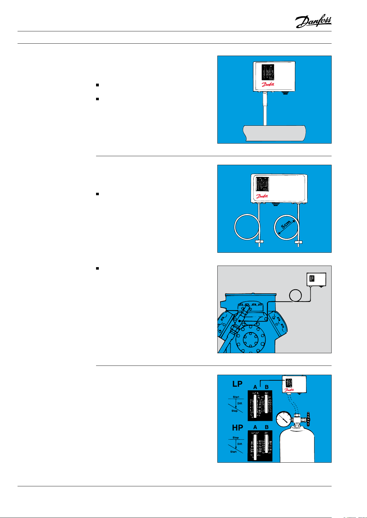
The pressure connection of the control must
always be fitted to the pipe in such a way that
liquid cannot collect in the bellows. This risk is
present especially when:
the unit is located in a low ambient condition,
e.g. in an air current,
the connection is made on the underside of
the pipe.
Such liquid could damage the high-pressure
control.
Consequently, compressor pulsation would
not be damped and might give rise to contact
chatter.
Surplus capillary tube can fracture if vibration
occurs and might lead to complete loss of system
charge. It is therefore very important that the
following rules are observed:
When mounting direct on compressor:
Secure the capillary tube so that the compressor/control installation vibrates as a
whole. Surplus capillary tube must be coiled
and bound.
Note:
According to EN rules it is not allowed to use
capillary tube for connecting safety pressure
controles. In such case a 1/4 inch tube is
prescribed.
Al0_0009
Al0_0010
Setting
Low-pressure control
High-pressure control
Other types of mounting:
Coil surplus capillary tube into a loose loop.
Secure the length of capillary tube between
compressor and loop to the compressor.
Secure the length of capillary tube between
loop and pressure control to the base on
which the pressure control is mounted.
In case of very strong vibrations, Danfoss
steel capillary tubes with flare connection are
recommended:
Code no. 0.5 m = 060-016666
Code no. 1.0 m = 060-016766
Code no. 1.5 m = 060-016866
KP pressure controls can be preset using a compressed air cylinder. Ensure that the change-over
contacts are correctly connected for the required
function.
Set the start pressure (CUT IN) on the range scale
(A). Then set the differential on the differential
scale (B).
Stop pressure = CUT IN minus DIFF.
Set the stop pressure (CUTOUT) on the range
scale (A). The set the differential on the
differential scale (B).
Start pressure = CUT OUT minus DIFF.
Remember: The scales are indicative only.
Al0_0011
Al0_0012
22 DKRCC.PF.000.G1.02 / 520H1459 © Danfoss A/S (AC-DSL/MWA), 10 - 2006
Page 25
Fitter notes Pressure controls
Example with four compressors
in parallel (R404A)
Setting LP for outdoor location
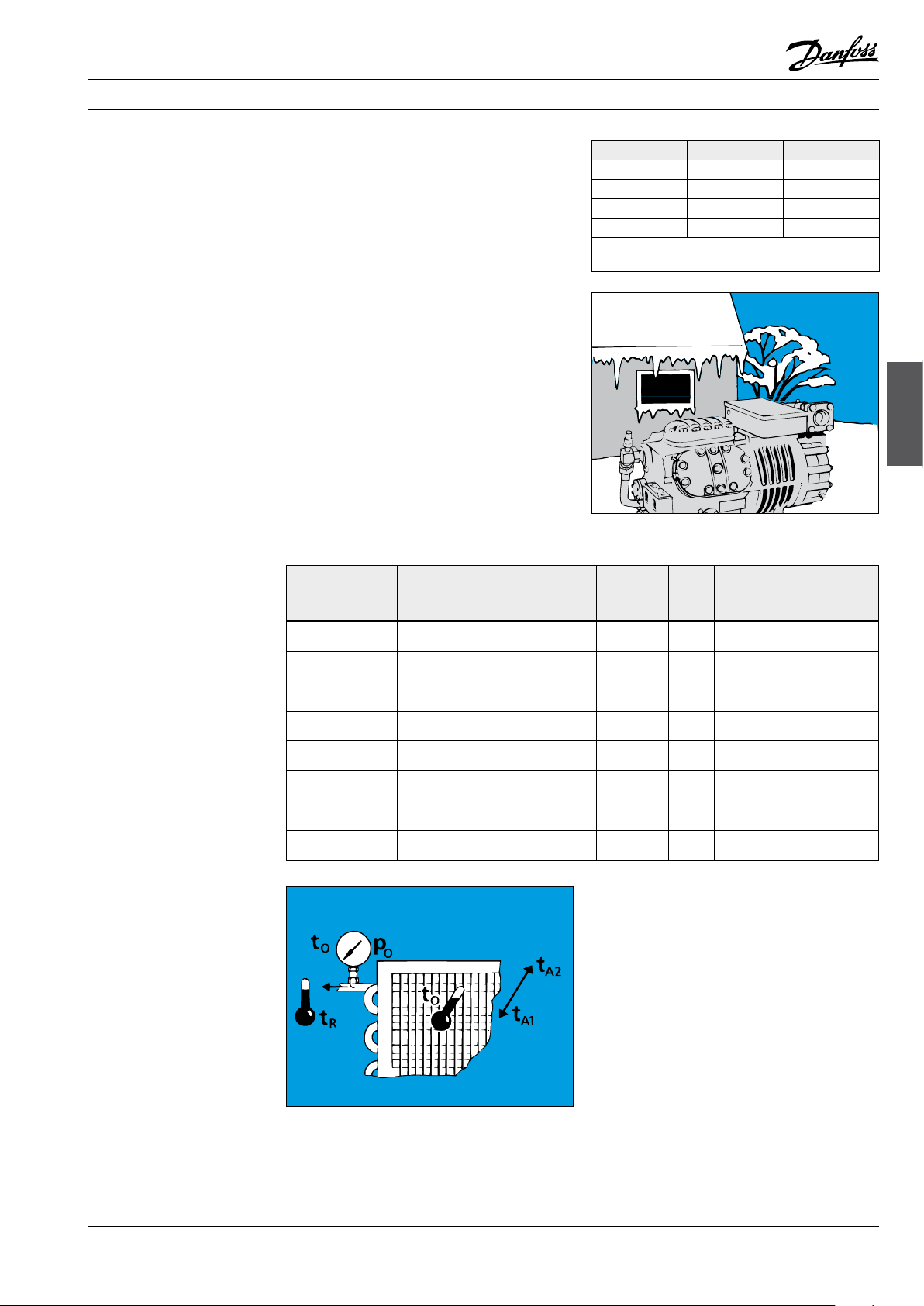
Indicative evaporating
pressures (pe) for different
types of systems
Medium: ice cream at –25°C,
t0 ≈ –37°C,
Compressor CUT OUT CUT IN
p0 ≈ –0.5 bar,
∆p suction line corresponding to 0.1 bar.
Each pressure control (e.g. KP 2) must be set
individually in accordance with the following
table.
The pressure control must be mounted in such
a way that liquid cannot collect in the bellows.
If the compressor, condenser and receiver are
situated outdoors, KP low pressure must be set to
a “CUT IN” setting lower than the lowest occurring
pressure (temperature around compressor)
during winter operation. In this case, after longer
standstill periods the pressure in the receiver
determines the suction pressure.
Example:
Lowest occurring temperature around the
compressor –20°C means, for R404A, a pressure
of 1 bar. CUT IN must be set at –24°C (corresponding to 1.6 bar).
Al0_0013
Room temp. (tr) System type Difference
+0.5°/+2°C Fan-cooled
meat cold room
+0.5°/+2°C Meat cold room with
natural air circulation
–1°/0°C Refrigeration meat
counter (open)
+2°/+6°C Milk cold room 14K 1.0 bar
0°/+2°C Fruit cold room
Vegetable chiller
–24°C Freezer 10K 1.6 bar
–30°C Ventilated deep
freeze room
–26°C Ice cream freezer 10K 1.4 bar
between te
and t
media
10K 1.0 - 1.1 bar
12K 0.8 - 0.9 bar
14K 0.6 bar
6K 1.3 - 1.5 bar
10K 1 bar
Evaporating
pressure (pe)
(air)
(R134a)
(R134a)
(R134a)
(R134a)
(R134a)
(R404A)
(R404A)
(R404A)
1 –0.05 bar 0.35 bar
2 0.1 bar 0.5 bar
3 0.2 bar 0.6 bar
4 0.35 bar 0.75 bar
RH
Setting of KP2/KP1
[%]
(cut in - cut out)
D = Operating press. cont.
S = Safety press. cont.
85 0.9 - 2.1 bar (D)
85 0.7 - 2.1 bar (D)
85 0.5 - 1.8 bar (D)
85 0.7 - 2.1 bar (D)
90 1.2 - 2.1 bar (D)
90 0.7 - 2.2 bar (S)
90 0.3 - 2.7 bar (S)
90 0.5 - 2.0 bar (S)
Pressure controls
Al0_0015
© Danfoss A/S (AC-DSL/MWA), 10 - 2006 DKRCC.PF.000.G1.02 / 520H1459 23
Page 26
Fitter notes Pressure controls
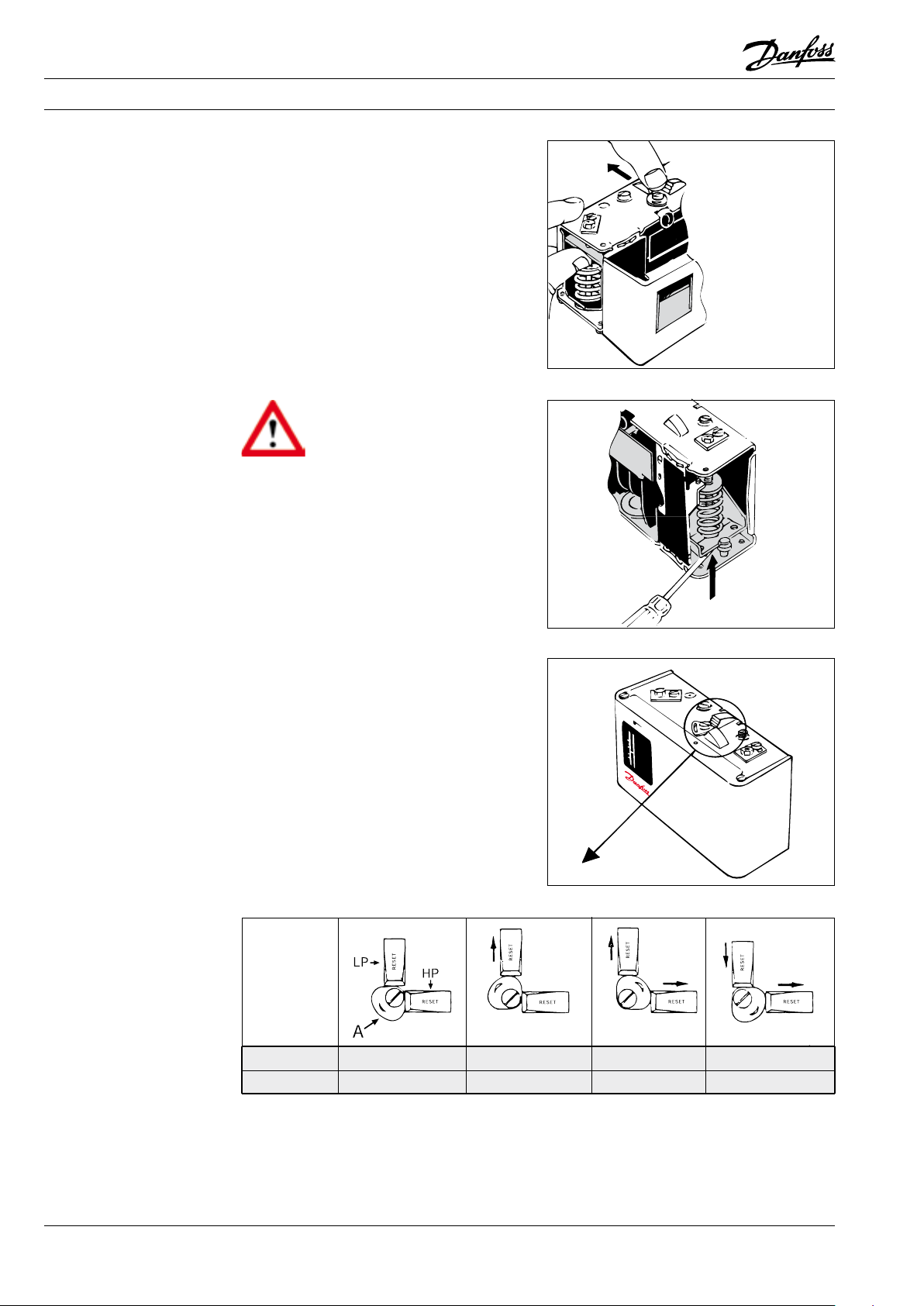
Test of contact function
When the electrical leads are connected and the
system is under normal operating pressure, the
contact function can be tested manually.
Depending on the bellows pressure and setting,
the test device must be pressed up or down.
Any reset mechanism becomes inoperative
during the test.
On single units:
Use the test device at top left.
On dual units:
Use the test device on the left for low-pressure
testing and the one at bottom right for highpressure testing.
Al0_0018
Warning!
The contact function on a KP
Pressure Control must never be
tested by activating the device at top
right. If this warning is ignored, the control may
go out of adjustment. In the worst case function
can be impaired.
Al0_0019
On the KP 15 dual pressure control with optional
automatic or manual reset on low-pressure
and high-pressure side, automatic reset must
be set when servicing is being carried out. The
pressure control can then automatically restart.
Remember, the original reset function must be
set after servicing.
The pressure control can be protected against
being set on automatic reset: Simply remove the
washer controlling the reset function!
If the unit is to be protected against tampering,
the washer can be sealed with red lacquer.
Al0_0020
Low pressure Manual reset *) Automatic reset Automatic reset Manual reset
High pressure Manual reset *) Manual reset Automatic reset Automatic reset
*) Factory setting
Al0_0021
24 DKRCC.PF.000.G1.02 / 520H1459 © Danfoss A/S (AC-DSL/MWA), 10 - 2006
Page 27
Fitter notes Pressure controls
The correct pressure control for your system
KP with solder connections can be used instead
of flare connections on hermetic systems.
In ammonia plant where KP pressure controls are
used, they must be type KP-A.
A connector with M10 × 0.75 – 1/
no. 060- 014166).
- 18 NPT (code
4
Al0_0006
Pressure controls
For refrigerating systems containing a large
quantity of charge medium and where extra
safety is desired/demanded (Fail-safe): Use KP
7/17 with double bellows. The system will stop
if one of the bellows ruptures - without loss of
charge.
For systems operating with low pressure on the
evaporator side, and where the pressure control
must regulate (not just monitor): Use KP 2 with a
small differential.
An example where pressure control and thermostat are in series:
KP 61 regulates the temperature via compressor
stop/start.
KP 2 stops the compressor when suction pressure
becomes too low.
KP 61:
CUT IN = 5°C (2.6 bar)
CUT OUT = 1°C (2.2 bar)
KP 2 low pressure:
CUT IN = 2.3 bar
CUT OUT = 1.8 bar
Al0_0002
Al0_0003
Al0_0004
© Danfoss A/S (AC-DSL/MWA), 10 - 2006 DKRCC.PF.000.G1.02 / 520H1459 25
Page 28
Fitter notes Pressure controls
The correct pressure control
for your system (cont.)
For systems where KP is activated occasionally
(alarm) and for systems where KP is the signal
source for PLC, etc.: Use KP with gold contacts;
these give good contact at low voltages.
Al0_0005
26 DKRCC.PF.000.G1.02 / 520H1459 © Danfoss A/S (AC-DSL/MWA), 10 - 2006
Page 29

Fitters notes Thermostats
Contents Page
Installation . . . . . . . . . . . . . . . . . . . . . . . . . . . . . . . . . . . . . . . . . . . . . . . . . . . . . . . . . . . . . . . . . . . . . . . . . . . . . . . . . . . . . . . 29
KP thermostat with air sensor . . . . . . . . . . . . . . . . . . . . . . . . . . . . . . . . . . . . . . . . . . . . . . . . . . . . . . . . . . . . . . . . . 29
Setting . . . . . . . . . . . . . . . . . . . . . . . . . . . . . . . . . . . . . . . . . . . . . . . . . . . . . . . . . . . . . . . . . . . . . . . . . . . . . . . . . . . . . . . . . . . 30
Thermostats with automatic reset . . . . . . . . . . . . . . . . . . . . . . . . . . . . . . . . . . . . . . . . . . . . . . . . . . . . . . . . . . . . . 30
Thermostats with maximum reset . . . . . . . . . . . . . . . . . . . . . . . . . . . . . . . . . . . . . . . . . . . . . . . . . . . . . . . . . . . . . 30
Thermostats with minimum reset . . . . . . . . . . . . . . . . . . . . . . . . . . . . . . . . . . . . . . . . . . . . . . . . . . . . . . . . . . . . . 30
Setting example . . . . . . . . . . . . . . . . . . . . . . . . . . . . . . . . . . . . . . . . . . . . . . . . . . . . . . . . . . . . . . . . . . . . . . . . . . . . . . . . . . 31
Test of contact function . . . . . . . . . . . . . . . . . . . . . . . . . . . . . . . . . . . . . . . . . . . . . . . . . . . . . . . . . . . . . . . . . . . . . . . . . . . 31
KP 98 dual thermostat . . . . . . . . . . . . . . . . . . . . . . . . . . . . . . . . . . . . . . . . . . . . . . . . . . . . . . . . . . . . . . . . . . . . . . . . 31
The correct thermostat for your refrigeration system. . . . . . . . . . . . . . . . . . . . . . . . . . . . . . . . . . . . . . . . . . . . . . . 32
Vapour charge. . . . . . . . . . . . . . . . . . . . . . . . . . . . . . . . . . . . . . . . . . . . . . . . . . . . . . . . . . . . . . . . . . . . . . . . . . . . . . . . 32
Absorption charge . . . . . . . . . . . . . . . . . . . . . . . . . . . . . . . . . . . . . . . . . . . . . . . . . . . . . . . . . . . . . . . . . . . . . . . . . . . . 32
Low voltage . . . . . . . . . . . . . . . . . . . . . . . . . . . . . . . . . . . . . . . . . . . . . . . . . . . . . . . . . . . . . . . . . . . . . . . . . . . . . . . . . . 32
Placing of surplus capillary tube. . . . . . . . . . . . . . . . . . . . . . . . . . . . . . . . . . . . . . . . . . . . . . . . . . . . . . . . . . . . . . . . . . . 33
Thermostats with vapour charge . . . . . . . . . . . . . . . . . . . . . . . . . . . . . . . . . . . . . . . . . . . . . . . . . . . . . . . . . . . . . . . . . . 33
Thermostats
© Danfoss A/S (AC-DSL/MWA), 10 - 2006 DKRCC.PF.000.G1.02 / 520H1459 27
Page 30

Notes
28 DKRCC.PF.000.G1.02 / 520H1459 © Danfoss A/S (AC-DSL/MWA), 10 - 2006
Page 31

Fitters notes Thermostats
Installation
If the risk of water droplets or water spray is
present, fit a top plate. The plate increases the
grade of enclosure to IP 44 and is suitable for all
KP thermostats. The top plate must be purchased
separately (Code no.: for single unit, 060-109766;
for dual unit, 060-109866).
To obtain IP 44, cover all holes in the backplate of
the thermostat.
If the unit is to be used in dirty conditions or
where it might be exposed to heavy spray it
should be fitted with a protective cap. The
cap can be used together with either an angle
bracket (060-105666) or a wall bracket (060-
105566).
Aj0_0001
Thermostats
KP thermostat with air sensor
Aj0_0002
If the unit risk being exposed to heavy water
influence a better grade of enclosure can be
achieved when mounting the product in a special
IP 55 enclosure
The IP 55 enclosure is available for both single
unit (060-033066) and dual unit (060-035066).
Ak0_0020
Remember that the differential is affected by
air circulation around the sensor. Insufficient air
circulation can increase the differential by 2-3°C.
Place the room thermostat so that air is able to
flow freely around the sensor. At the same time,
ensure that the sensor is not exposed to draughts
from doors or radiation from the evaporator
surface.
Never place the thermostat directly on a cold
wall; this increases the differential. Instead,
mount the unit on an insulating plate.
Aj0_0003
© Danfoss A/S (AC-DSL/MWA), 10 - 2006 DKRCC.PF.000.G1.02 / 520H1459 29
Page 32

Fitters notes Thermostats
KP thermostat with air sensor
(cont.)
Setting
Thermostats with
automatic reset
When placing the sensor: Remember that air
must be able to circulate freely around the
sensor. With control from, for example, return
air temperature, the sensor must not touch the
evaporator.
KP thermostat with cylindrical sensor
There are three ways of securing the sensor:
1) The pipe.
2) Between evaporator fins.
3) In a pocket.
Always set the highest temperature on the range
scale. Then set the differential on the DIFF scale.
The temperature setting on the range scale
then corresponds to the temperature at which a
refrigeration compressor will be started on rising
temperature. The compressor will stop when the
temperature corresponds to the value set on the
DIFF scale.
For pre-setting of vapour charged thermostats,
the graph curves stated in the customer
instruction sheet should be used.
If the compressor will not stop when it is set for
low stop temperatures: Check to see whether
the differential has been set at too high a value.
Ah0_0006
When using a pocket: Always use heat-conductive compound (code no. 041E0110) to ensure
good contact between sensor and medium.
Aj0_0004
Aj0_0005
Thermostats with
maximum reset
Set the highest temperature = stop temperature
on range scale.
The differential setting is fixed. When the temperature on the thermostat sensor corresponds
to the differential setting, the system can be
restarted by pressing the "Reset" button.
Thermostats with
minimum reset
Set the lowest temperature = stop temperature
on range scale.
The differential setting is fixed.
When the temperature around the thermostat
sensor has risen to the differential setting, the
compressor can be restarted by pressing the
“Reset” button.
Aj0_0006
30 DKRCC.PF.000.G1.02 / 520H1459 © Danfoss A/S (AC-DSL/MWA), 10 - 2006
Page 33

Fitters notes Thermostats
Setting example
Test of contact function
The temperature in a deep freeze room is to be
controlled by a thermostat that closes a solenoid
valve. The system is of the pump-down type and
is stopped via a low-pressure control.
Here, the pressure control must not be set to
cut out at a pressure lower than necessary.
At the same time, it must cut in at a pressure
corresponding to the cut-in temperature of the
thermostat.
Example:
Deep freeze room with R404A
Room temperature: –20°C
Thermostat cut out temperature: –20°C
Thermostat cut in temperature: –18°C
Pressure control cut out
pressure: 0.9 bar (–32°C)
Pressure control cut in
pressure: 2.2 bar (–18°C)
Thermostats
Aj0_0007
When the electrical leads are connected, the
contact function can be tested manually.
Depending on the sensor temperature and
the thermostat setting, the test device must
be pressed up or down. Any reset mechanism
becomes inoperative during the test.
Use the test device at top left.
KP 98 dual thermostat
Aj0_0009
Warning!
The contact function on a KP
single thermostat must never
be tested by activating the
device on the righthand side. If this warning
is ignored, the thermostat might go out of
adjustment. In the worst case, function can be
impaired.
Use the test device on the lefthand side to
test function on rising oil temperature and the
test device at bottom right to test function on
rising pressure gas temperature.
Aj0_0010
© Danfoss A/S (AC-DSL/MWA), 10 - 2006 DKRCC.PF.000.G1.02 / 520H1459 31
Page 34

Fitters notes Thermostats
The correct thermostat for
your refrigeration system
Vapour charge
Absorption charge
A thermostat must contain the correct charge, as
described below.
Low temperatures, coldest bellows, not enclosure-sensitive.
Thermostat with air coil: On gradual temperature
rise and fall (less than 0.2K/min), e.g. in large,
sluggish cold rooms containing many items, KP
62 with vapour charge is recommended.
High temperatures, enclosure-sensitive. Bellows
colder or warmer.
Thermostat with air coil: On fast changes in
temperature (more than 0.2K/ min), e.g. in
smaller cold rooms where the produce turnover
rate is high, KP 62 with absorption charge is
recommended.
Straight
capillary tube
60I8012
Remote air coil
60I8032
Vapour charge
Air coil
(integral with
thermostat)
60I8013
Double contact
remote bulb
60I8017
Cylindric
remote bulb
60I8008
Low voltage
For systems where KP is activated occasionally
(alarm) and for systems where KP is the signal
source for PLC, etc. (low voltage): Use KP with
gold contacts; these give good contact at low
voltages.
Absorption charge
Aj0_0012
Air coil
(integral with
thermostat)
60I8013
Remote air coil
(for duct mounting)
60I8018
32 DKRCC.PF.000.G1.02 / 520H1459 © Danfoss A/S (AC-DSL/MWA), 10 - 2006
Page 35

Fitters notes Thermostats
Placing of surplus
capillary tube
Thermostats with
vapour charge
Dual thermostat KP 98:
Surplus capillary tube can fracture if vibration
occurs and might lead to loss of thermostat
charge. It is therefore very important that the
following rules be observed:
When mounting direct on compressor:
Secure the capillary tube so that the
compressor/thermostat installation vibrates as
a whole. Surplus capillary tube must be coiled
and bound.
Other types of mounting: Coil surplus capillary
tube into a loose loop. Secure the length of
capillary tube between compressor and loop
to the compressor.
Secure the length of capillary tube between
loop and thermostat to the base on which the
thermostat is mounted.
Never locate a KP thermostat with vapour charge
in a room where the temperature is or can be
lower than that in the cold room.
Aj0_0017
Thermostats
Never allow the capillary tube from a KP
thermostat to run alongside of a suction line in a
wall entry.
Aj0_0014
Aj0_0015
© Danfoss A/S (AC-DSL/MWA), 10 - 2006 DKRCC.PF.000.G1.02 / 520H1459 33
Page 36

Page 37

Fitters notes Pressure regulators
Contents Page
Application. . . . . . . . . . . . . . . . . . . . . . . . . . . . . . . . . . . . . . . . . . . . . . . . . . . . . . . . . . . . . . . . . . . . . . . . . . . . . . . . . . . . . . . 37
KVP evaporating pressure regulator . . . . . . . . . . . . . . . . . . . . . . . . . . . . . . . . . . . . . . . . . . . . . . . . . . . . . . . . . . . 37
KVR condensing pressure regulator. . . . . . . . . . . . . . . . . . . . . . . . . . . . . . . . . . . . . . . . . . . . . . . . . . . . . . . . . . . . 38
KVL crankcase pressure regulator. . . . . . . . . . . . . . . . . . . . . . . . . . . . . . . . . . . . . . . . . . . . . . . . . . . . . . . . . . . . . . 38
KVC capacity regulator . . . . . . . . . . . . . . . . . . . . . . . . . . . . . . . . . . . . . . . . . . . . . . . . . . . . . . . . . . . . . . . . . . . . . . . . 39
KVD receiver pressure regulator . . . . . . . . . . . . . . . . . . . . . . . . . . . . . . . . . . . . . . . . . . . . . . . . . . . . . . . . . . . . . . . 39
Identification . . . . . . . . . . . . . . . . . . . . . . . . . . . . . . . . . . . . . . . . . . . . . . . . . . . . . . . . . . . . . . . . . . . . . . . . . . . . . . . . . . . . . 40
Installation . . . . . . . . . . . . . . . . . . . . . . . . . . . . . . . . . . . . . . . . . . . . . . . . . . . . . . . . . . . . . . . . . . . . . . . . . . . . . . . . . . . . . . . 40
Soldering/brazing . . . . . . . . . . . . . . . . . . . . . . . . . . . . . . . . . . . . . . . . . . . . . . . . . . . . . . . . . . . . . . . . . . . . . . . . . . . . . . . . 40
Pressure testing . . . . . . . . . . . . . . . . . . . . . . . . . . . . . . . . . . . . . . . . . . . . . . . . . . . . . . . . . . . . . . . . . . . . . . . . . . . . . . . . . . 41
Evacuation . . . . . . . . . . . . . . . . . . . . . . . . . . . . . . . . . . . . . . . . . . . . . . . . . . . . . . . . . . . . . . . . . . . . . . . . . . . . . . . . . . . . . . . 41
Setting . . . . . . . . . . . . . . . . . . . . . . . . . . . . . . . . . . . . . . . . . . . . . . . . . . . . . . . . . . . . . . . . . . . . . . . . . . . . . . . . . . . . . . . . . . . 42
KVP evaporating pressure regulators . . . . . . . . . . . . . . . . . . . . . . . . . . . . . . . . . . . . . . . . . . . . . . . . . . . . . . . . . . 42
KVL crankcase pressure regulators. . . . . . . . . . . . . . . . . . . . . . . . . . . . . . . . . . . . . . . . . . . . . . . . . . . . . . . . . . . . . 42
KVR + NRD condensing pressure regulators. . . . . . . . . . . . . . . . . . . . . . . . . . . . . . . . . . . . . . . . . . . . . . . . . . . . 42
KVR + KVD condensing pressure regulators . . . . . . . . . . . . . . . . . . . . . . . . . . . . . . . . . . . . . . . . . . . . . . . . . . . . 43
Danfoss pressure regulators. . . . . . . . . . . . . . . . . . . . . . . . . . . . . . . . . . . . . . . . . . . . . . . . . . . . . . . . . . . . . . . . . . . . . . . 43
regulators
Pressure
© Danfoss A/S (AC-DSL/MWA), 10 - 2006 DKRCC.PF.000.G1.02 / 520H1459 35
Page 38

Notes
36 DKRCC.PF.000.G1.02 / 520H1459 © Danfoss A/S (AC-DSL/MWA), 10 - 2006
Page 39

Fitters notes Pressure regulators
Application
KVP evaporating
pressure regulator
Type KV pressure regulators will control the low
and high pressure sides of the system under
varying load conditions:
KVP is used as an evaporating pressure
regulator.
KVR is used as a condensing pressure regulator.
KVL is used as a crankcase pressure regulator.
KVC is used as a capacity regulator.
NRD is used as a differential pressure regulator
and as a receiver pressure regulator.
KVD is used as a receiver pressure regulator.
CPCE is used as a capacity regulator.
The evaporating pressure regulator is installed in
the suction line after the evaporator to regulate
the evaporating pressure in refrigeration systems with one or more evaporators and one
compressor.
In such refrigeration systems (operating on
different evaporating pressures) KVP is installed
after the evaporator with the highest evaporating
pressure.
Each evaporator is activated by a solenoid valve
in the liquid line. The compressor is contolled by
a pressure switch in a pump down function.
The maximum pressure on the suction side
corresponds to the lowest room temperature.
Ak0_0031
Ak0_0025
regulators
Pressure
In refrigeration systems with parallel coupled
evaporators and common compressors, and
where the same evaporating pressure is required,
KVP must be installed in the common suction
line.
The KVP evaporating pressure regulator has a
pressure gauge connection for use when setting
the evaporating pressure. KVP maintains constant
pressure in the evaporator.
KVP opens on rising inlet pressure (evaporating
pressure).
Ak0_0019
Ak0_0023
© Danfoss A/S (AC-DSL/MWA), 10 - 2006 DKRCC.PF.000.G1.02 / 520H1459 37
Page 40

Fitters notes Pressure regulators
KVR condensing
pressure regulator
KVR is normally installed between the air-cooled
condenser and the receiver. KVR maintains
constant pressure in air-cooled condensers.
It opens on rising inlet pressure (condensing
pressure).
KVR together with a KVD or an NRD ensures a
sufficiently high liquid pressure in the receiver
during varying operating conditions.
The KVR condensing pressure regulator has a
pressure gauge connection for use when setting
the condensing pressure.
Ak0_0026
In situations where both the air-cooled condenser and the receiver are located outdoors in
very cold surroundings it can be difficult to start
the refrigeration system after a long standstill
period.
In such conditions, KVR is installed ahead of the
air-cooled condenser, with an NRD in a bypass
line around the condenser.
NRV prevent back flow during start up process.
Ak0_0027
KVR is also used in heat recovery. In this
application, KVR is installed between the heat
recovery vessel and condenser.
It is necessary to install an NRV between condenser and receiver in order to prevent backcondensation of the liquid in the condenser.
Ak0_0028
KVR can be used as a relief valve in refrigeration
systems with automatic defrosting. Here, KVR
is installed between the outlet tube from
evaporator and receiver.
Note!
KVR must never be used as a safety valve.
Ak0_0029
KVL crankcase
pressure regulator
KVL crankcase pressure regulator limits compressor operation and start-up if the suction
pressure becomes too high.
It is installed in the refrigeration system suction
line immediately ahead of the compressor.
KVL is often used in refrigeration systems with
hermetic or semihermetic compressors designed
for low-temperature ranges.
KVL opens on falling outlet pressure (suction
pressure).
Ak0_0024
38 DKRCC.PF.000.G1.02 / 520H1459 © Danfoss A/S (AC-DSL/MWA), 10 - 2006
Page 41

Fitters notes Pressure regulators
KVC capacity regulator
KVC is used for capacity regulation in refrigeration systems where low-load situations occur
and where it is necessary to avoid low suction
pressure and “compressor cycling”.
Too low a suction pressure will also cause
vacuum in the refrigeration system and thus
create the risk of moisture ingress in refrigeration
systems with open compressor. KVC is normally
installed in a bypass line between compressor
discharge tube and suction tube. KVC opens on
falling outlet pressure (suction pressure).
Ak0_0030
A CPCE capacity regulator can be used as
an alternative to KVC if the requirement
is greater accuracy in the regulation, low
suction pressure or if higher pressure drop is
given between CPCE outlet and the suction
pressure.
KVD receiver
pressure regulator
KVC can also be installed in a bypass line from
the compressor discharge pipe, with valve outlet
led to a point between expansion valve and
evaporator.
This arrangement can be used on a liquid cooler
with several parallelcoupled compressors and
where no liquid distributor is used.
KVD is used to maintain sufficiently high
receiver pressure in refrigeration systems with
or without heat recovery.
KVD is used together with a KVR condensing
pressure regulator.
The KVD receiver pressure regulator has a
pressure gauge connection for use when
setting receiver pressure.
KVD opens on falling outlet pressure (receiver
pressure).
Ak0_0002
Ak0_0003
regulators
Pressure
Ak0_0004
© Danfoss A/S (AC-DSL/MWA), 10 - 2006 DKRCC.PF.000.G1.02 / 520H1459 39
Page 42

Fitters notes Pressure regulators
PS
Identification
All KV pressure regulators carry a label giving the
valve function and type, e.g. CRANKCASE PRESS.
REGULATOR type KVL.
The label also gives the operating range of the
valve and its max. permissible working pressure
(PS/MWP).
A double-ended arrow (“+” and “-“) is printed
on the bottom of the label. Direction “+” (plus)
means higher pressure and “–“ (minus) means
lower pressure.
KV pressure regulators can be used with all
existing refrigerants except ammonia (NH3),
provided valve pressure ranges are respected.
The valve body is stamped with the valve size,
e.g. KVP 15, with an arrow to indicate valve flow
direction.
Ak0_0032
Ak0_0005
Installation
Soldering/brazing
Ensure that piping around KV valves is clean and
well-secured. This will protect valves against
vibration.
All KV pressure regulators must always be
installed so that flow is in the direction of the
arrow.
KV pressure regulators can otherwise be installed
in any position, but they must never be able to
create an oil or liquid lock.
Ak0_0006
During soldering, it is important to wrap a wet
cloth around the valve.
Always point the gas flame away from the valve
so that the valve is never subjected to direct heat.
When soldering, be careful not to leave soldering
material in the valve as this can impair function.
Before soldering a KV valve, be sure that any
pressure gauge insert has been removed. Always
use inert gas when soldering KV valves.
Ak0_0007
Warning!
Alloys in soldering materials and
flux give off smoke which can be
hazardous to health. Please read
gases. It is a good idea to use safety goggles.
Soldering while refrigerant is present in the
system is not recommended.
suppliers’ instructions and follow their safety
precautions. Keep the head away from the smoke
during soldering. Use good ventilation and/or an
extract at the flame and do not inhale smoke and
Aggressive gases might be created which can, for
example, break down the bellows in KV valves or
other parts in the refrigeration system.
40 DKRCC.PF.000.G1.02 / 520H1459 © Danfoss A/S (AC-DSL/MWA), 10 - 2006
Page 43

Fitters notes Pressure regulators
Pressure testing
Evacuation
KV pressure regulators can be pressure-tested
after they have been installed, provided the
test pressure does not exceed the maximum
permissible pressure on the valves.
The maximum test pressure for KV valves is
shown in the table.
During evacuation of the refrigeration system, all
KV valves must be open.
Factory-set KV valves will have the following
positions when supplied:
KVP, closed
KVR, closed
KVL, open
KVC, open
KVD, open
It is therefore necessary to screw the setting
spindle of KVP and KVR right back counterclockwise during system evacuation.
In individual cases it can be necessary to
evacuate from both discharge side and lowpressure side in the refrigeration system.
Evacuation through the pressure gauge connections of KVP, KVR and KVD is not advisable because the orifice in these ports are very small.
Type Test pressure, bar
KVP 12 - 15 - 22 28
KVP 28 - 35 25
KVL 12 - 15 - 22 28
KVL 28 - 35 25
KVR 12 - 15 - 22 31
KVR 28 - 35 31
KVD 12 - 15 31
KVC 12 - 15 - 22 31
regulators
Pressure
Ak0_0009
© Danfoss A/S (AC-DSL/MWA), 10 - 2006 DKRCC.PF.000.G1.02 / 520H1459 41
Page 44

Fitters notes Pressure regulators
Setting
KVP evaporating
pressure regulators
When setting KV pressure regulators in refrigeration systems it can be a good idea to use
the factory setting as the starting-out point.
The factory setting for individual pressure
regulators can be found again by measuring
from the top of the valve to the top of the
setting screw.
The table shows the factory setting, the
distance “x” and the pressure change per
revolution of the setting screw for all KV types.
KVP evaporating pressure regulators are always
supplied with a factory setting of 2 bar. Turning
clockwise gives higher pressure and turning
counterclockwise gives lower pressure.
After the system has been in normal operation for
a time, fine adjustment is necessary. Always use a
pressure gauge when making fine adjustments.
If KVP is used for frost protection, fine adjustment
must be made when the system is operating
under minimum load.
Remember to always replace the protective cap
on the setting screw after final setting.
Type
KVP 12 - 15 - 22 2 bar 13 0.45
KVP 28 - 35 2 bar 19 0.30
KVL 12 - 15 - 22 2 bar 22 0.45
KVL 28 - 35 2 bar 32 0.30
KVR 12 - 15 -22 10 bar 13 2.5
KVR 28 - 35 10 bar 15 1.5
KVD 12 - 15 10 bar 21 2.5
KVC 12 - 15 - 22 2 bar 13 0.45
Ak0_0010
Factory
setting
X mm bar/rev.
KVL crankcase
pressure regulators
KVR + NRD condensing
pressure regulators
Ak0_0011
KVL crankcase pressure regulators are always
supplied with a factory setting of 2 bar.
Turning clockwise gives higher pressure and
turning counterclockwise gives lower pressure.
The factory setting is the point at which KVL
begins to open or where it just closes. Since the
compressor must be protected, the KVL setting is
the max. permissible suction pressure of the
compressor.
The setting must be made using the compressor
suction pressure gauge.
Ak0_0012
In refrigeration systems with KVR + NRD, the
setting of KVR must give a suitable receiver
pressure.
Pressure in the condenser of between 1.4 and 3.0
bar (pressure drop across NRD) higher than the
pressure in the receiver should be acceptable. If it
cannot be accepted, an arrangement with KVR +
KVD must be used.
This setting is best made during operating in a
winter period.
Ak0_0013
42 DKRCC.PF.000.G1.02 / 520H1459 © Danfoss A/S (AC-DSL/MWA), 10 - 2006
Page 45

Fitters notes Pressure regulators
KVR + KVD condensing
pressure regulators
In refrigeration systems with KVR + KVD, the
condensing pressure must first be set with KVR
while KVD is closed (setting screw turned back
fully counterclockwise).
Then, KVD must be set to a receiver pressure, e.g.
about 1 bar lower than condensing pressure.
A pressure gauge must be used for this setting
which is best made during operation in a winter
period.
If the condensing pressure is set during summer
operation, one of two procedures can be used:
1) In a newly-installed refrigeration system with
a KVR/KVD setting of 10 bar as the starting
out point, the system can be set by counting
the number of turns on the setting screw.
2) In an existing refrigeration system, where
the KVR/KVD setting is not known, the
Ak0_0014
starting-out point must first be established.
The number of turns on the setting screw
can then be counted.
Danfoss pressure regulators
Product Used as Opens Pressure range
KVP Evaporating pressure regulator on a rise in pressure on the inlet side 0 - 5.5 bar
KVR Condensing pressure regulator on a rise in pressure on the inlet side 5 - 17.5 bar
regulators
Pressure
KVL Crankcase pressure regulator at a fall in pressure on the outlet side 0.2 - 6 bar
KVC Capacity regulator at a fall in pressure on the outlet side 0.2 - 6 bar
CPCE Capacity regulator at a fall in pressure on the outlet side 0 - 6 bar
NRD Differential pressure regulator Begins to open when the pressure drop in the
3 - 20 bar
valve is 1.4 bar, and is fully open when the
pressure drop is 3 bar.
KVD Receiver pressure regulator at a fall in pressure on the outlet side 3 - 20 bar
© Danfoss A/S (AC-DSL/MWA), 10 - 2006 DKRCC.PF.000.G1.02 / 520H1459 43
Page 46

Page 47

Fitters notes Water valves
Contents Page
Application. . . . . . . . . . . . . . . . . . . . . . . . . . . . . . . . . . . . . . . . . . . . . . . . . . . . . . . . . . . . . . . . . . . . . . . . . . . . . . . . . . . . . . . 47
Identification . . . . . . . . . . . . . . . . . . . . . . . . . . . . . . . . . . . . . . . . . . . . . . . . . . . . . . . . . . . . . . . . . . . . . . . . . . . . . . . . . . . . . 47
Installation . . . . . . . . . . . . . . . . . . . . . . . . . . . . . . . . . . . . . . . . . . . . . . . . . . . . . . . . . . . . . . . . . . . . . . . . . . . . . . . . . . . . . . . 48
Setting . . . . . . . . . . . . . . . . . . . . . . . . . . . . . . . . . . . . . . . . . . . . . . . . . . . . . . . . . . . . . . . . . . . . . . . . . . . . . . . . . . . . . . . . . . . 48
Maintenance . . . . . . . . . . . . . . . . . . . . . . . . . . . . . . . . . . . . . . . . . . . . . . . . . . . . . . . . . . . . . . . . . . . . . . . . . . . . . . . . . . . . . 49
Spare parts . . . . . . . . . . . . . . . . . . . . . . . . . . . . . . . . . . . . . . . . . . . . . . . . . . . . . . . . . . . . . . . . . . . . . . . . . . . . . . . . . . . . . . . 50
Water valves
© Danfoss A/S (AC-DSL/MWA), 10 - 2006 DKRCC.PF.000.G1.02 / 520H1459 45
Page 48

Notes
46 DKRCC.PF.000.G1.02 / 520H1459 © Danfoss A/S (AC-DSL/MWA), 10 - 2006
Page 49

Fitters notes Water valves
Application
Identification
WV pressure-operated water valves are used
in refrigeration systems with water-cooled
condensers to maintain constant condensing
pressure under varying loads.
The water valves can be used for common
refrigerants provided the operating range of the
valves is not exceeded. The WVS can be
used for R717 (ammonia)
Ag0_0001
Danfoss water valve type WVFM consists of a
valve body and bellows housing. The bellows
housing carries a label giving valve type,
operating range and max. permissible working
pressure.
The label also indicates the max. permissible
working pressure on the water side, given as PN
10 in accordance with IEC 534-4.
The direction in which the setting spindle must
be turned for greater or lesser water quantity is
given at the bottom of the valve.
Ag0_0002
Water valve type WVFX consists of a valve body
with setting unit on one side and a bellows
housing on the other.
The bellows housing carries a label giving valve
type, operating range and permissible working
pressure.
All pressures given apply to the condenser side.
Moulded in on one side of the valve body are PN
16 (nom. pressure) and, for example, DN 15 (nom.
diameter), together with kvs 1.9 (valve capacity in
m3/h at a pressure drop of 1 bar).
RA and DA are moulded in on the opposite side
of the valve body.
RA means “reverse acting” and DA means “direct
acting”.
When WVFX is used as a condensing pressure
valve the bellows housing must always be
mounted nearest the DA marking.
Water valves
Ag0_0003
Ag0_0004
© Danfoss A/S (AC-DSL/MWA), 10 - 2006 DKRCC.PF.000.G1.02 / 520H1459 47
Page 50

Fitters notes Water valves
Installation
WVFM and WVFX are installed in the water line,
normally ahead of the condenser, with flow in the
direction of the arrow.
It is a good idea to always install an FV filter
ahead of the water valve to exclude dirt from the
moving parts of the valve.
To prevent vibrations from being transmitted
to the bellows housing the housing must be
connected to the discharge line after the oil
separator, via a capillary tube.
The capillary tube must be connected to the top
side of the discharge line to prevent the backflow of oil and perhaps dirt.
WVFM and WVFX 32-40 water valves are normally installed with bellows housing upwards.
Ag0_0005
Ag0_0006
Setting
WVFX 10-25 water valves can be installed in any
position.
WVFM and WVFX water valves must be set
to obtain the required condensing pressure.
Turning the setting spindle clockwise gives lower
pressure, turning it counterclockwise gives higher
pressure.
The scale marks 1 - 5 can be used for coarse
setting. Scale mark 1 corresponds to about 2 bar,
and scale mark 5 corresponds to about 17 bar.
Note that the valve setting range is given for
when the valve begins to open.
The condensing pressure must increase by 3 bar
to fully open the valve.
Ag0_0007
Ag0_0008
48 DKRCC.PF.000.G1.02 / 520H1459 © Danfoss A/S (AC-DSL/MWA), 10 - 2006
Page 51

Fitters notes Water valves
Maintenance
It is a good idea to include water valves in
preventive maintenance because dirt (sludge)
can collect around the moving parts of the valves.
The maintenance routine can include flushing the
water valves, partly to wash out impurities and
partly to be able to “sense” whether the reaction
of valves has become slower.
Ag0_0009
Flushing a WVFM water valve is easiest to
perform if two screwdrivers are inserted under
the setting screw.
The screw can then be levered up to give greater
water flow.
Ag0_0010
WVFX valves can be flushed similarly using two
screwdrivers inserted in the slots on each side of
the setting unit (spring housing) and under the
spring cup.
Levering the screwdrivers down towards the
piping gives greater water flow.
If operating irregularities appear in a water
valve, or if leakage occurs across the valve seat,
dismantle the valve and clean it.
Before dismantling a valve, the pressure must
always be relieved from the bellows housing, i.e.
it must be disconnected from the refrigeration
system condenser.
Before dismantling, screw the setting spring fully
clockwise towards the lowest pressure setting.
The O-ring and remaining seals must always be
replaced after dismantling.
Water valves
Ag0_0011
Ag0_0012
© Danfoss A/S (AC-DSL/MWA), 10 - 2006 DKRCC.PF.000.G1.02 / 520H1459 49
Page 52

Fitters notes Water valves
Spare parts
Spare parts for WVFM and WVFX water valves can
be obtained from Danfoss:
one bellows housing.
one service kit (containing spare parts,
gaskets and grease for the water side of the
valve).
A gasket set is also supplied as a spare part for
type WVFM.
The code numbers of spare parts and gasket sets
are given in the spare parts catalogue*.
Ag0_0013
*) Find spare part documentation on http://www.danfoss.com
50 DKRCC.PF.000.G1.02 / 520H1459 © Danfoss A/S (AC-DSL/MWA), 10 - 2006
Page 53

Fitters notes Filter driers & sight glasses
Contents Page
Function . . . . . . . . . . . . . . . . . . . . . . . . . . . . . . . . . . . . . . . . . . . . . . . . . . . . . . . . . . . . . . . . . . . . . . . . . . . . . . . . . . . . . . . . . 53
Filter drier selection. . . . . . . . . . . . . . . . . . . . . . . . . . . . . . . . . . . . . . . . . . . . . . . . . . . . . . . . . . . . . . . . . . . . . . . . . . . . . . . 53
Location in refrigeration system. . . . . . . . . . . . . . . . . . . . . . . . . . . . . . . . . . . . . . . . . . . . . . . . . . . . . . . . . . . . . . . . . . . 54
Installation . . . . . . . . . . . . . . . . . . . . . . . . . . . . . . . . . . . . . . . . . . . . . . . . . . . . . . . . . . . . . . . . . . . . . . . . . . . . . . . . . . . . . . . 55
Soldering. . . . . . . . . . . . . . . . . . . . . . . . . . . . . . . . . . . . . . . . . . . . . . . . . . . . . . . . . . . . . . . . . . . . . . . . . . . . . . . . . . . . . . . . . 56
Operation . . . . . . . . . . . . . . . . . . . . . . . . . . . . . . . . . . . . . . . . . . . . . . . . . . . . . . . . . . . . . . . . . . . . . . . . . . . . . . . . . . . . . . . . 56
Replace the filter drier when . . . . . . . . . . . . . . . . . . . . . . . . . . . . . . . . . . . . . . . . . . . . . . . . . . . . . . . . . . . . . . . . . . 56
DCR . . . . . . . . . . . . . . . . . . . . . . . . . . . . . . . . . . . . . . . . . . . . . . . . . . . . . . . . . . . . . . . . . . . . . . . . . . . . . . . . . . . . . . . . . . 57
Using gaskets. . . . . . . . . . . . . . . . . . . . . . . . . . . . . . . . . . . . . . . . . . . . . . . . . . . . . . . . . . . . . . . . . . . . . . . . . . . . . . . . . . . . . 57
Mounting gaskets. . . . . . . . . . . . . . . . . . . . . . . . . . . . . . . . . . . . . . . . . . . . . . . . . . . . . . . . . . . . . . . . . . . . . . . . . . . . . 57
Disposal. . . . . . . . . . . . . . . . . . . . . . . . . . . . . . . . . . . . . . . . . . . . . . . . . . . . . . . . . . . . . . . . . . . . . . . . . . . . . . . . . . . . . . . . . . 57
Filter drier replacement . . . . . . . . . . . . . . . . . . . . . . . . . . . . . . . . . . . . . . . . . . . . . . . . . . . . . . . . . . . . . . . . . . . . . . . . . . . 57
Special filters from Danfoss . . . . . . . . . . . . . . . . . . . . . . . . . . . . . . . . . . . . . . . . . . . . . . . . . . . . . . . . . . . . . . . . . . . . . . . 58
Combidriers type DCC and DMC. . . . . . . . . . . . . . . . . . . . . . . . . . . . . . . . . . . . . . . . . . . . . . . . . . . . . . . . . . . . . . . 58
Burn-out filter, type 48-DA . . . . . . . . . . . . . . . . . . . . . . . . . . . . . . . . . . . . . . . . . . . . . . . . . . . . . . . . . . . . . . . . . . . . 58
Special application . . . . . . . . . . . . . . . . . . . . . . . . . . . . . . . . . . . . . . . . . . . . . . . . . . . . . . . . . . . . . . . . . . . . . . . . . . . . . . . 58
DCL/DML filter driers. . . . . . . . . . . . . . . . . . . . . . . . . . . . . . . . . . . . . . . . . . . . . . . . . . . . . . . . . . . . . . . . . . . . . . . . . . 58
Dimensioning . . . . . . . . . . . . . . . . . . . . . . . . . . . . . . . . . . . . . . . . . . . . . . . . . . . . . . . . . . . . . . . . . . . . . . . . . . . . . . . . . . . . 59
EPD (Equilibrium Point Dryness) . . . . . . . . . . . . . . . . . . . . . . . . . . . . . . . . . . . . . . . . . . . . . . . . . . . . . . . . . . . . . . . 59
Drying capacity (water capacity). . . . . . . . . . . . . . . . . . . . . . . . . . . . . . . . . . . . . . . . . . . . . . . . . . . . . . . . . . . . . . . 59
Liquid capacity (ARI 710*) . . . . . . . . . . . . . . . . . . . . . . . . . . . . . . . . . . . . . . . . . . . . . . . . . . . . . . . . . . . . . . . . . . . . . 59
Recommended system capacity . . . . . . . . . . . . . . . . . . . . . . . . . . . . . . . . . . . . . . . . . . . . . . . . . . . . . . . . . . . . . . . 60
Filter driers from Danfoss . . . . . . . . . . . . . . . . . . . . . . . . . . . . . . . . . . . . . . . . . . . . . . . . . . . . . . . . . . . . . . . . . . . . . . . . . 60
© Danfoss A/S (AC-DSL/MWA), 10 - 2006 DKRCC.PF.000.G1.02 / 520H1459 51
Filter driers &
sight glasses
Page 54

Notes
52 DKRCC.PF.000.G1.02 / 520H1459 © Danfoss A/S (AC-DSL/MWA), 10 - 2006
Page 55

Fitters notes Filter driers & sight glasses
Function
To ensure optimum function the refrigeration
system must be internally clean and dry.
Before starting the system, moisture must be
removed by evacuation at a max. pressure of 0.05
mbar abs.
During operation, dirt and moisture must be
collected and removed. This is performed by a
filter drier containing a solid core consisting of:
Molecular Sieves
Silica gel (low effectiveness - not used in
Danfoss driers)
Activated aluminium oxide and a polyester
mesh A inserted in the filter outlet.
DML: 100% Molecular Sieves
DCL: 80% Molecular Sieves
20% Activated aluminium
The solid core can be compared to a sponge’s
ability to soak up water and retain it.
Molecular Sieves retain water, whereas activated
aluminium oxide retains water and acids.
The solid core B together with the polyester mat
A also acts as a dirt filter.
The solid core retains large dirt particles and the
polyester mat small ones.
The filter drier is thus able to collect all dirt
particles larger than 25 micron.
Ah0_0001
Filter drier selection
The filter drier must be selected to suit the
connections and the capacity of the refrigeration
system.
If a filter drier with solder connections is required,
a Danfoss type DCL/DML filter drier can be
used to advantage. It has an extra-high drying
capacity which prolongs the interval between
replacements.
A collar on the connector A indicates that the
connection is a mm size. If the connector A is
plain, i.e. no collar, the connector is an inch size.
Type DCL can be used for CFC/HCFC refrigerants.
Type DML can be used for HFC refrigerants. See
page 60 for more details.
Ah0_0011
Ah0_0018
Filter driers &
sight glasses
© Danfoss A/S (AC-DSL/MWA), 10 - 2006 DKRCC.PF.000.G1.02 / 520H1459 53
Page 56

Fitters notes Filter driers & sight glasses
Location in
refrigeration system
The filter drier is normally installed in the liquid
line where its primary function is to protect the
expansion valve.
The velocity of the refrigerant in the liquid
line is low and therefore contact between the
refrigerant and the solid core in the filter drier is
good. At the same time, the pressure drop across
the filter drier is low.
A filter drier can also be installed in the suction
line where its task is to protect the compressor
against dirt and dry the refrigerant.
Suction filters, so-called “burn-out” filters, are
used to remove acids after motor damage. To
ensure low pressure drop, a suction filter must
normally be larger than a liquid line filter.
A suction filter must be replaced before the
pressure drop exceeds the following values:
A/C systems: 0.50 bar
Refrigeration systems: 0.25 bar
Freezing systems: 0.15 bar
A sight glass with moisture indicator is normally
installed after the filter drier, where the sight
glass indication means:
Green: No dangerous moisture in the refrigerant.
Yellow: Moisture content too high in the
refrigerant ahead of the expansion valve.
Bubbles:
1) Pressure drop across the filter drier too high.
2) No subcooling.
3) Insufficient refrigerant in whole system.
Ah0_0019
Ah0_0020
If the sight glass is installed ahead of the filter
drier the indication is:
Green: No dangerous moisture in the refrigerant.
Yellow: Moisture content in the whole
refrigeration system too high.
The changeover point from green to yellow in the
sight glass indicator is determined by the water
solubility of the refrigerant.
Note:
The changeover points in Danfoss sight glasses
are very small. This ensures that a switch to green
in the indicator only occurs when the refrigerant
is dry.
Bubbles:
1) No subcooling.
2) Insufficient refrigerant in whole system.
Note!
Do not replenish refrigerant solely because of
bubbles in the sight glass.
First find out the cause of the bubbles!
Ah0_0032
Ah0_0031
Ah0_0006
54 DKRCC.PF.000.G1.02 / 520H1459 © Danfoss A/S (AC-DSL/MWA), 10 - 2006
Page 57

Fitters notes Filter driers & sight glasses
Installation
The filter drier must be installed with flow in the
direction of the arrow on the filter drier label.
The filter drier can have any orientation, but the
following must be remembered:
Vertical mounting with downward flow means
rapid evacuation/emptying of the refrigeration
system.
With vertical mounting and upward flow,
evacuation/emptying takes longer because
refrigerant must be evaporated out of the filter
drier.
The filter core is firmly fixed in the filter housing.
Danfoss filter driers are therefore able to resist
vibration up to 10 g*).
Find out whether the tubing will support the
filter drier and resist vibration. If not, the filter
drier must be installed using a clamping band or
similar secured to a rigid part of the system.
*) 10 g = Ten times the gravitational force of the earth.
For DCR: Install with the inlet connector upwards
or horizontal.
This avoids collected dirt running out into the
tubing when the core is replaced.
When installing a new DCR, remember that
there must always be sufficient space for core
replacement.
Ah0_0022
Ah0_0028
Do not unpack filter driers or cores until immediately before installation. This will safe-guard the
items in the best possible way.
There is neither vacuum nor overpressure in
filters or cans.
Plastic union nuts, capsolutes and the hermetically sealed can guarantee completely “fresh”
desiccants.
Ah0_0002
Ah0_0003
Filter driers &
sight glasses
© Danfoss A/S (AC-DSL/MWA), 10 - 2006 DKRCC.PF.000.G1.02 / 520H1459 55
Page 58

Fitters notes Filter driers & sight glasses
Soldering
Operation
Protective gas, e.g. N2, should be used when
soldering the filter drier.
Ensure that the protective gas flows in the
direction of filter flow. This avoids heat from
soldering being damaging the polyester mesh.
Soldering alloys and flux give off
fumes that can be hazardous.
Read supplier instructions and
observe their safety stipulations.
Keep your head away from the
fumes during soldering.
Moisture enters the system:
1) When the refrigeration system is being built
up.
2) When the refrigeration system is opened for
servicing.
3) If leakage occurs on the suction side, if it is
under vacuum.
4) When the system is filled with oil or
refrigerant containing moisture.
5) If leakage occurs in a water-cooled condenser.
Moisture in the refrigeration system can cause:
a) Blockage of the expansion device because of
ice formation.
b) Corrosion of metal parts.
c) Chemical damage to the insulation in
hermetic and semihermetic compressors.
d) Oil breakdown (acid formation).
The filter drier removes moisture that remains
after evacuation or that subsequently enters the
refrigeration system.
Ah0_0004
Use strong ventilation and/or extraction at the
flame so that you do not inhale fumes and gases.
Use protective goggles.
Use wet cloth around filter driers with pure
copper connectors.
Ah0_0005
Warning!
Never use “antifreeze liquids” like
methyl alcohol together with a filter
drier. Such liquid can damage the
filter so that it is unable to absorb
water and acid.
Replace the filter drier when
1. The sight glass indicates that the moisture
content is too high (yellow).
2. Pressure drop across the filter is too high
(bubbles in sight glass during normal
operation).
3. A main component in the refrigerant system
has been replaced, e.g. the compressor.
4. Each time the refrigeration system is
otherwise opened, e.g. if the orifice assembly
in an expansion valve is replaced.
Never re-use a used filter drier. It will give off
moisture if it is used in a refrigeration system with
low moisture content, or if it becomes heated.
Ah0_0008
56 DKRCC.PF.000.G1.02 / 520H1459 © Danfoss A/S (AC-DSL/MWA), 10 - 2006
Page 59

Fitters notes Filter driers & sight glasses
DCR
Using gaskets
Mounting gaskets
Note, there can be overpressure in the filter.
Therefore be careful when opening the filter.
Never re-use the flange gasket in the DCR filter.
Fit a new gasket and smear it with a little refri-
geration machine oil before tightening.
Only use undamaged gaskets.
Flange surfaces that are to form the seal must
be faultless, clean and dry before mounting.
Do not use adhesive filler, rust remover
or similar chemicals when mounting or
dismantling.
1. Moisten gasket surfaces with a drop of
refrigerant oil.
2. Put gasket in place.
3. Mount bolts and tighten slightly until all bolts
have made good contact.
4. Cross-tighten bolts.
Ah0_0009
Use sufficient oil for lubricating bolts and
screws during mounting.
Do not use bolts which are dry, corroded or
defective in any other way (defective bolts can
give incorrect tightening which may result in
leaking flange joints).
Tighten bolts in at least 3-4 steps, e.g. as follows:
Step 1: to approx. 10% of required torque.
Step 2: to approx. 30% of required torque.
Step 3: to approx. 60% of required torque.
Step 4: to 100% of required torque.
Finally, check that the torque is correct in the
same order as used when tightening.
Disposal
Filter drier replacement
Always seal used filter driers. They contain small
amounts of refrigerant and oil residue.
Observe authority requirements when scrapping
used filter driers.
Close valve no. 1.
Suck the filter empty.
Close valve no. 4.
Close valve no. 2.
The system will now operate, bypassing the filter.
Replace filter or filter core.
Evacuate the filter drier via a schrader valve
(no. 3).
Restart the system by opening/closing the
valves in the reverse order.
Remove any levers/handwheels from the
valves.
Ah0_0023
Ah0_0014
Filter driers &
sight glasses
© Danfoss A/S (AC-DSL/MWA), 10 - 2006 DKRCC.PF.000.G1.02 / 520H1459 57
Page 60

Fitters notes Filter driers & sight glasses
Special filters from Danfoss
Combidriers type DCC and DMC
Burn-out filter, type 48-DA
Combidriers type DCC and DMC are used in
smaller systems with expansion valve where the
condenser cannot contain the entire quantity of
refrigerant.
The receiver in the combidrier increases liquid
subcooling and creates the possibility of
automatic defrost on pumpdown. The receiver
takes up varying refrigerant volume (from varying
condensing temperature) and must be able to
contain the whole refrigerant quantity during
service and repair.
In the interests of safety, the volume of the
receiver must be at least 15% greater than the
refrigerant volume.
Burn-out filter, type 48-DA, is for use after a
hermetic or semihermetic compressor has
suffered damage.
Compressor damage that gives rise to acid
formation will be revealed by oil odour and
perhaps discolouration. Damage can occur
because of:
moisture, dirt or air
defective starter
refrigerant failure because of too small a
refrigerant charge,
hot gas temperature higher than 175°C
Ah0_0012
Ah0_0013
After replacing the compressor and cleaning
the remainder of the system, two burn-out
filters are installed; one in the liquid line and
one in the suction line.
The acid content is then checked regularly
and the filters replaced as necessary.
When an oil check shows that the system no
longer contains acid, the burn-out filter in
the liquid line can be replaced by an ordinary
filter drier. The burn-out filter core in the
suction line can be removed.
Ah0_0010
Special application
DCL/DML filter driers
Type DCL/DML 032s, DCL/DML 032.5s and
DCL/DML 033s are manufactured specially for
capillary tube systems and are therefore used in
refrigeration systems where expansion is through
a capillary tube.
Ah0_0017
DCL/DML filter driers can also be used when
reparing refrigerators and freezers, etc. Both time
and money can be saved by installing a DCL/DML
filter drier in the suction line.
The advantage of doing so can best be illustrated
by comparing the normal repair procedure for a
defective compressor with a method that exploits
the good characteristics of the DCL/DML filter in
retaining moisture, acid and dirt.
NOTE: The „DCL/DML method“ can only be used
when the oil is not discoloured and when
the pencil filter is not clogged.
Ah0_0015
58 DKRCC.PF.000.G1.02 / 520H1459 © Danfoss A/S (AC-DSL/MWA), 10 - 2006
Page 61

Fitters notes Filter driers & sight glasses
Special application
DCL/DML filter driers (cont.)
Dimensioning
The advantages gained by installing a DCL/DML
filter in the suction line are:
1. Faster repair.
2. Increased drying and acid capacity.
3. Protection of the compressor against
impurities of every kind.
4. Better quality of repair.
5. Cleaner working environment.
The acid and moisture bound in the old oil will be
absorbed by the DCL/DML filter.
Therefore it is not necessary to remove remaining
oil from the refrigeration system.
A DCL/DML in the suction line retains impurities
from condenser, evaporator, tubing, etc. and
thereby prolongs the life of the new compressor.
DCL/DML filters having the same connections
as the compressor can be used. The Danfoss
range of hermetic compressors can also be
recommended.
When choosing filter driers from catalogues there
are several expressions each of which can form
the basis of selection.
Procedure with pencil filter Procedure with
Recover refrigerant and
evaluate for re-use
Remove compressor
+ pencil filter
Remove oil residue in system Nothing
Dry system with nitrogen Nothing
Connect new compressor and
fit new pencil filter
Evaluate and change
refrigerant
DCL/DML filter
Recover refrigerant and
evaluate for re-use
Remove compressor
Connect new compressor
and fit DCL/DML filter in
suction line
Evaluate and change
refrigerant
Example:
Compressor type Suction tube
TL Ø6.2 DCL/DML 032s
NL 6-7 Ø6.2 DCL/DML 032s
[mm]
Filter type
EPD (Equilibrium Point Dryness)
Drying capacity (water capacity)
Liquid capacity (ARI 710*)
Defines the least possible water content in a
refrigerant in its liquid phase, after it has been in
contact with a filter drier.
EPD for R22 = 60 ppmW *)
EPD for R410A = 50 ppmW *)
EPD for R134a = 50 ppmW *)
EPD for R404A / R507 / R407C = 50 ppmW *)
As stipulated by ARI 710, in ppmW
(mg
/kg
water
*) ARI: Air-conditioning and Refrigeration Institute, Virginia, USA
refrigerant
)
The quantity of water the filter drier is able to
absorb at 24°C and 52°C liquid temperature, as
stipulated by the ARI 710* standard.
The drying capacity is given in grams of water,
drops of water or kg refrigerant on drying out.
R22: 1050 ppmW to 60 ppmW
R410A: 1050 ppmW to 50 ppmW
R134a: 1050 ppmW to 50 ppmW
R404A / R507 / R407C: 1020 ppmW to 50 ppmW
1000 ppmW = 1 g water in 1 kg refrigerant 1 g water = 20 drops.
Gives the quantity of liquid able to flow through
a filter with a pressure drop of 0.07 bar at tc =
+30°C, te = -15°C.
The liquid capacity is stated in l/min or in kW.
Conversion from kW to litres/minute:
R22 / R410A 1kW = 0.32 l/min
R134a 1kW = 0.35 l/min
R404A / R507 / R407C 1kW = 0.52 l/min
*) ARI: Air-conditioning and Refrigeration Institute, Virginia, USA
Ah0_0025
Ah0_0016
Ah0_0024
Filter driers &
sight glasses
© Danfoss A/S (AC-DSL/MWA), 10 - 2006 DKRCC.PF.000.G1.02 / 520H1459 59
Page 62

Fitters notes Filter driers & sight glasses
Recommended system capacity
Filter driers from Danfoss
Operating conditions:Stated in kW for different types of refrigeration
systems on the basis of a liquid capacity of
∆p = 0.14 bar and typical operating conditions.
Refrigeration
and freezing systems
A/C systems
A/C units
te = evaporating temperature
tc = condensing temperature
te = -15°C, tc = +30°C
te = -5°C, tc = +45°C
te = +5°C, tc = +45°C
Warning:
With the same system capacity in
kW for A/C units and for
refrigeration/freezing systems,
smaller filter driers can be installed
in A/C units because of higher evaporating
temperature (te) and the assumption that factory
produced units contain less moisture than
systems built up „on site“.
Product type Function Refrigerant Core Oil type
DML Standard filter drier HFC, compatible with
DCL Standard filter drier CFC/HCFC 80% molecular sieves
DMB Bi-flow filter drier HFC, compatible with
DCB Bi-flow filter drier CFC/HCFC 80% molecular sieves
DMC Combi filter drier HFC, compatible with
DCC Combi filter drier CFC/HCFC 80% molecular sieves
DAS Burn-out filter drier R22, R134a,
DCR Filter drier with ex-
48-DU/DM
for DCR
48-DN/DC
for DCR
48-DA
for DCR
48-F
for DCR
changeable core
Exchangeable core for
DCR: std. filter drier
Exchangeable core for
DCR: std. filter drier
Exchangeable core for
DCR: std. filter drier
Exchangeable
core for DCR with
exchangeable filter
insert
R22
R22
R22
R404A, R507
See core description
below
HFC, compatible with
R22
CFC/HCFC 80% molecular sieves
R22, R134a,
R404A, R507
All - All
100% molecular sieves Polyolester (POE)
20% activated alumina
100% molecular sieves Polyolester (POE)
20% activated alumina
100% molecular sieves Polyolester (POE)
20% activated alumina
30% molecular sieves
70% activated alumina
48-DU/DM, 48-DN DC,
48-DA, 48-F
100% molecular sieves Polyolester (POE)
20% activated alumina
Polyalkyl (PAG)
Mineral oil (MO)
Alkyl benzene (BE)
Polyalkyl (PAG)
Mineral oil (MO)
Alkyl benzene (BE)
Polyalkyl (PAG)
Mineral oil (MO)
Alkyl benzene (BE)
-
Polyalkyl (PAG)
Mineral oil (MO)
Alkyl benzene (BE)
60 DKRCC.PF.000.G1.02 / 520H1459 © Danfoss A/S (AC-DSL/MWA), 10 - 2006
Page 63

Fitters notes Danfoss compressors
Page
This chapter is divided into four sections:
Mounting instructions . . . . . . . . . . . . . . . . . . . . . . . . . . . . . . . . . . . . . . . . . . . . . . . . . . . . . . . . . . . . . . . . . . . . . . . . . . . . 63
Condensing units in general . . . . . . . . . . . . . . . . . . . . . . . . . . . . . . . . . . . . . . . . . . . . . . . . . . . . . . . . . . . . . . . . . . . . . . 81
Repair of hermetic refrigeration systems. . . . . . . . . . . . . . . . . . . . . . . . . . . . . . . . . . . . . . . . . . . . . . . . . . . . . . . . . . . 95
Practical application of refrigerant R290 propane in small hermetic systems . . . . . . . . . . . . . . . . . . . . . . . 115
© Danfoss A/S (AC-DSL/MWA), 10 - 2006 DKRCC.PF.000.G1.02 / 520H1459 61
compressors
Danfoss
Page 64

Page 65

Fitters notes Danfoss compressors - Mounting Instructions
Contents Page
1.0 General. . . . . . . . . . . . . . . . . . . . . . . . . . . . . . . . . . . . . . . . . . . . . . . . . . . . . . . . . . . . . . . . . . . . . . . . . . . . . . . . . . . . . . . 65
2.0 Compressor . . . . . . . . . . . . . . . . . . . . . . . . . . . . . . . . . . . . . . . . . . . . . . . . . . . . . . . . . . . . . . . . . . . . . . . . . . . . . . . . . . 65
2.1 Denomination. . . . . . . . . . . . . . . . . . . . . . . . . . . . . . . . . . . . . . . . . . . . . . . . . . . . . . . . . . . . . . . . . . . . . . . . . . . . . 65
2.2 Low and High starting torque. . . . . . . . . . . . . . . . . . . . . . . . . . . . . . . . . . . . . . . . . . . . . . . . . . . . . . . . . . . . . . 66
2.3 Motor protector and winding temperature . . . . . . . . . . . . . . . . . . . . . . . . . . . . . . . . . . . . . . . . . . . . . . . . . 66
2.4 Rubber grommets . . . . . . . . . . . . . . . . . . . . . . . . . . . . . . . . . . . . . . . . . . . . . . . . . . . . . . . . . . . . . . . . . . . . . . . . . 66
2.5 Minimum ambient temperature . . . . . . . . . . . . . . . . . . . . . . . . . . . . . . . . . . . . . . . . . . . . . . . . . . . . . . . . . . . 67
3.0 Fault finding. . . . . . . . . . . . . . . . . . . . . . . . . . . . . . . . . . . . . . . . . . . . . . . . . . . . . . . . . . . . . . . . . . . . . . . . . . . . . . . . . . 67
3.1 Winding protector cut-out. . . . . . . . . . . . . . . . . . . . . . . . . . . . . . . . . . . . . . . . . . . . . . . . . . . . . . . . . . . . . . . . . 67
3.2 PTC and protector interaction. . . . . . . . . . . . . . . . . . . . . . . . . . . . . . . . . . . . . . . . . . . . . . . . . . . . . . . . . . . . . . 67
3.3 Check of winding protector and resistance . . . . . . . . . . . . . . . . . . . . . . . . . . . . . . . . . . . . . . . . . . . . . . . . . 67
4.0 Opening the refrigeratingsystem . . . . . . . . . . . . . . . . . . . . . . . . . . . . . . . . . . . . . . . . . . . . . . . . . . . . . . . . . . . . . . 67
4.1 Flammable refrigerants. . . . . . . . . . . . . . . . . . . . . . . . . . . . . . . . . . . . . . . . . . . . . . . . . . . . . . . . . . . . . . . . . . . . 68
5.0 Mounting . . . . . . . . . . . . . . . . . . . . . . . . . . . . . . . . . . . . . . . . . . . . . . . . . . . . . . . . . . . . . . . . . . . . . . . . . . . . . . . . . . . . 68
5.1 Connectors. . . . . . . . . . . . . . . . . . . . . . . . . . . . . . . . . . . . . . . . . . . . . . . . . . . . . . . . . . . . . . . . . . . . . . . . . . . . . . . . 68
5.2 Drifting out connectors. . . . . . . . . . . . . . . . . . . . . . . . . . . . . . . . . . . . . . . . . . . . . . . . . . . . . . . . . . . . . . . . . . . . 70
5.3 Tube adapters . . . . . . . . . . . . . . . . . . . . . . . . . . . . . . . . . . . . . . . . . . . . . . . . . . . . . . . . . . . . . . . . . . . . . . . . . . . . . 70
5.4 Solders. . . . . . . . . . . . . . . . . . . . . . . . . . . . . . . . . . . . . . . . . . . . . . . . . . . . . . . . . . . . . . . . . . . . . . . . . . . . . . . . . . . . 70
5.5 Soldering . . . . . . . . . . . . . . . . . . . . . . . . . . . . . . . . . . . . . . . . . . . . . . . . . . . . . . . . . . . . . . . . . . . . . . . . . . . . . . . . . 71
5.6 Lokring connections. . . . . . . . . . . . . . . . . . . . . . . . . . . . . . . . . . . . . . . . . . . . . . . . . . . . . . . . . . . . . . . . . . . . . . . 72
5.7 Driers . . . . . . . . . . . . . . . . . . . . . . . . . . . . . . . . . . . . . . . . . . . . . . . . . . . . . . . . . . . . . . . . . . . . . . . . . . . . . . . . . . . . . 72
5.8 Driers and refrigerants. . . . . . . . . . . . . . . . . . . . . . . . . . . . . . . . . . . . . . . . . . . . . . . . . . . . . . . . . . . . . . . . . . . . . 73
5.9 Capillary tube in drier. . . . . . . . . . . . . . . . . . . . . . . . . . . . . . . . . . . . . . . . . . . . . . . . . . . . . . . . . . . . . . . . . . . . . . 73
6.0 Electrical equipment. . . . . . . . . . . . . . . . . . . . . . . . . . . . . . . . . . . . . . . . . . . . . . . . . . . . . . . . . . . . . . . . . . . . . . . . . . 74
6.1 LST starting device . . . . . . . . . . . . . . . . . . . . . . . . . . . . . . . . . . . . . . . . . . . . . . . . . . . . . . . . . . . . . . . . . . . . . . . . 74
6.2 HST starting equipment . . . . . . . . . . . . . . . . . . . . . . . . . . . . . . . . . . . . . . . . . . . . . . . . . . . . . . . . . . . . . . . . . . . 75
6.3 HST CSR starting equipment . . . . . . . . . . . . . . . . . . . . . . . . . . . . . . . . . . . . . . . . . . . . . . . . . . . . . . . . . . . . . . . 77
6.4 Equipment for SC twincompressors . . . . . . . . . . . . . . . . . . . . . . . . . . . . . . . . . . . . . . . . . . . . . . . . . . . . . . . . 77
6.5 Electronic unit for variable speed compressors . . . . . . . . . . . . . . . . . . . . . . . . . . . . . . . . . . . . . . . . . . . . . 78
7.0 Evacuation . . . . . . . . . . . . . . . . . . . . . . . . . . . . . . . . . . . . . . . . . . . . . . . . . . . . . . . . . . . . . . . . . . . . . . . . . . . . . . . . . . . 78
7.1 Vacuum pumps. . . . . . . . . . . . . . . . . . . . . . . . . . . . . . . . . . . . . . . . . . . . . . . . . . . . . . . . . . . . . . . . . . . . . . . . . . . . 79
8.0 Charging of refrigerant. . . . . . . . . . . . . . . . . . . . . . . . . . . . . . . . . . . . . . . . . . . . . . . . . . . . . . . . . . . . . . . . . . . . . . . . 79
8.1 Maximum refrigerant charge. . . . . . . . . . . . . . . . . . . . . . . . . . . . . . . . . . . . . . . . . . . . . . . . . . . . . . . . . . . . . . . 79
8.2 Closing the process tube. . . . . . . . . . . . . . . . . . . . . . . . . . . . . . . . . . . . . . . . . . . . . . . . . . . . . . . . . . . . . . . . . . . 79
9.0 Testing . . . . . . . . . . . . . . . . . . . . . . . . . . . . . . . . . . . . . . . . . . . . . . . . . . . . . . . . . . . . . . . . . . . . . . . . . . . . . . . . . . . . . . . 80
9.1 Testing of the appliance . . . . . . . . . . . . . . . . . . . . . . . . . . . . . . . . . . . . . . . . . . . . . . . . . . . . . . . . . . . . . . . . . . . 80
compressors
Danfoss
© Danfoss A/S (AC-DSL/MWA), 10 - 2006 DKRCC.PF.000.G1.02 / 520H1459 63
Page 66

Notes
64 DKRCC.PF.000.G1.02 / 520H1459 © Danfoss A/S (AC-DSL/MWA), 10 - 2006
Page 67

Fitters notes Danfoss compressors - Mounting Instructions
1.0
General
2.0
Compressor
When a compressor has to be installed in new
appliances normally sufficient time is available
to choose the right compressor type from
datasheets and make sufficient testing.
Contrary when a faulty compressor has to be
replaced it can in many cases be impossible to
get the same compressor type as the original.
In such cases it is necessary to compare relevant
compressor catalogue data.
Long lifetime for a compressor can be expected
if the service work is done in the right way and
cleanness and dryness of the components are
taken into consideration.
The programme of Danfoss compressors consists
of the basic types P, T, N, F, SC and SC Twin.
Danfoss 220 V compressors have a yellow label
with information of the type designation, voltage
and frequency, application, starting conditions,
refrigerant and code number.
The 115 V compressors have a green label.
LST/HST mentioned both means that the starting
characteristics are depending on the electrical
equipment.
The service technician has to observe the
following when choosing a compressor.
Type of refrigerant, voltage and frequency,
application range, compressor displacement/
capacity, starting con-ditions and cooling
conditions.
If possible use the same refrigerant type as in the
faulty system.
2.1
Denomination
If the type label has been destroyed, the
compressor type and the code number can
be found in the stamping on the side of the
compressor. See first pages in collection of
datasheets for the compressor.
Example of compressor denomination
T L E S 4 F K
Basic design (P, T, N, F, S)
L, R, C = int. motor protection
T, F = ext. motor protection
LV = variable speed
E = energy optimization
Y = High energy optimization
S = semi direct suction
Nominal displacement in cm
3
A = LBP / (MBP) R12
AT = LBP (tropical) R12
B = LBP / MBP / HBP R12
BM = LBP (240 V) R22
C = LBP R502 / (R22)
CL = LBP R404A/ R507
CM = LBP R22 / R502
CN = LBP R290
D = HBP R22
DL = HBP R404A/ R507
F = LBP R134a
FT = LBP (tropical) R134a
G = LBP/MBP/HBP R134a
GH = Heat pumps R134a
GHH = Heat pumps (optimized) R134a
H = Heat pumps R12
HH = Heat pumps (optimized) R12
K = LBP/(MBP) R600a
KT = LBP (tropical) R600a
MF = MBP R134a
ML = MBP R404A/R507
Am0_0024
Am0_0025
empty = LST / HST
K = Capillary tube (LST)
X = Expansion valve (HST)
compressors
Danfoss
© Danfoss A/S (AC-DSL/MWA), 10 - 2006 DKRCC.PF.000.G1.02 / 520H1459 65
Page 68

Fitters notes Danfoss compressors - Mounting Instructions
3327-
Com
p
ressor bas
e
Gr
ommet sleeve
Washer
Nut M6
Cabinet base
Screw M6 x 25
Rubber grommet
2.1
Denomination (cont.)
2.2
Low and High starting torque
The first letter of the denomination (P, T, N, F or S)
indicates compressor series whereas the second
letter indicates motor protection placing.
E, Y and X mean different energy optimization
steps. S means semi direct suction. V means
variable speed compressors. On all these
mentioned types the indicated suction connector
has to be used. Using the wrong connector as
suction connector will lead to reduced capacity
and efficiency.
A number indicates the displacement in cm3,
but for PL compressors the number indicates the
nominal capacity.
The letter after the displacement indicates which
refrigerant must be used as well as the field of
application for the compressor. (See example)
LBP (Low Back Pressure) indicates the range of
low evaporating temperatures, typically -10°C
down to -35°C or even -45°C,for use in freezers
and refrigerators with freezer compartments.
MBP (Medium Back Pressure) indicates the range
of medium evaporating temperatures, typically
Description of the different electrical equipments
shown can be found in the datasheets for the
compressors. See also section 6.0.
Low starting torque (LST) compressors must
only be used in refrigerating systems having
capillary tube throttling device where pressure
equalization is obtained between suction and
discharge sides during each standstill period.
A PTC starting device (LST) requires that the
standstill time is at least 5 minutes, since this is
the time necessary for cooling the PTC.
The HST starting device, which gives the
compressor a high starting torque, must always
-20°C up to 0°C, such as in cold cabinets, milk
coolers, ice machines and water coolers.
HBP (High Back Pressure) indicates high
evaporating temperatures, typically -5°C up to
+15°C, such as in dehumidifiers and some liquid
coolers.
T as extra character indicates a compressor
intended for tropical application. This means high
ambient temperatures and capability of working
with more unstable power supply.
The final letter in the compressor denomination
provides information on the starting torque. If,
as principal rule, the compressor is intended for
LST (Low Starting Torque) and HST (High Starting
Torque), the place is left empty. The starting
characteristics are depending on the electrical
equipment chosen.
K indicates LST (capillary tube and pressure
equalization during standstill) and X
indicates HST (expansion valve or no pressure
equalization).
be used in refrigeration systems with expansion
valve, and for capillary tube systems without full
pressure equalization before each start.
High stating torque (HST) compressors are
normally using a relay and starting capacitor as
starting device.
The starting capacitors are designed for short
time cut-in.
“1.7% ED”, which is stamped onto the starting
capacitor, means for instance max. 10 cut-ins per
hour each with a duration of 6 seconds.
2.3
Motor protector and
winding temperature
2.4
Rubber grommets
Most of the Danfoss compressors are equipped
with a built-in motor protector (winding
protector) in the motor windings. See also
section 2.1.
Stand the compressor on the base plate until it is
fitted.
This reduces the risk of oil coatings inside the
connectors and associated brazing problems.
Place the compressor on its side with the
connectors pointing upwards and then fit the
rubber grommets and grommet sleeves on the
base plate of the compressor.
Do not turn the compressor upside down.
Mount the compressor on the baseplate of the
appliance.
At peak load the winding temperature must
not exceed 135°C and at stable conditions the
winding temperature must not exceed 125°C.
Specific information on some special types can
be found in the collection of data sheets.
Am0_0026
Am0_0027
66 DKRCC.PF.000.G1.02 / 520H1459 © Danfoss A/S (AC-DSL/MWA), 10 - 2006
Page 69

Fitters notes Danfoss compressors - Mounting Instructions
M S
C
Start winding
Winding protector
Main winding
2.5
Minimum ambient temperature
3.0
Fault finding
3.1
Winding protector cut-out
3.2
PTC and protector interaction
3.3
Check of winding protector
and resistance
Allow the compressor to reach a temperature
above 10°C before starting the first time to avoid
starting problems.
If the compressor does not operate, it could have
many reasons. Before replacing the compressor, it
should be made sure, that it is defect.
If the winding protector cuts out while the
compressor is cold, it can take approx 5 minutes
for the protector to reset.
The PTC starting unit requires a cooling time of 5
minutes before it can restart the compressor with
full starting torque.
Short time power supply cut offs, not long
enough to allow the PTC to cool down, can result
in start failure for up to 1 hour.
The PTC will not be able to provide full action
during the first protector resets, as they typically
In the event of compressor failure a check is
made by means of resistance measurement
directly on the current lead-in to see whether
the defect is due to motor damage or simply a
temporarily cut out of the winding protector.
If tests with resistance measurement reveal a
connection through the motor windings from
point M to S of the current lead-in, but broken
circuit between point M and C and S and C this
indicates that the winding protector is cut out.
Therefore, wait for resetting.
For easy failure location, please see the section
“Trouble shooting”.
If the winding protector cuts out while the
compressor is warm (compressor housing above
80°C) the resetting time is increased. Up to
approx 45 minutes may pass before reset.
do not allow pressure equalization also. Thus the
protector trips until the reset time is long
enough.
This mismatch condition can be solved by
unplugging the appliance for 5 to 10 minutes
typically.
Am0_0028
4.0
Opening the refrigerating
system
Never open a refrigerating system before all
components for the repair are available.
Compressor, drier and other system components
must be sealed off until a continuous assembly
can occur.
Opening a defect system must be done in
different ways depending on the refrigerant used.
Fit a service valve to the system and collect the
refrigerant in the right way.
If the refrigerant is flammable it can be released
outside in the open air through a hose if the
amount is very limited.
Then flush the system with dry nitrogen.
compressors
Danfoss
© Danfoss A/S (AC-DSL/MWA), 10 - 2006 DKRCC.PF.000.G1.02 / 520H1459 67
Page 70

Fitters notes Danfoss compressors - Mounting Instructions
TL
E
C
or
D
D
or
C
PL
C
E
D
NL
C
E
D
FR
E
C
D
SC
D
C
E
C
D
E
TLS
4.1
Flammable refrigerants
R600a and R290 are hydrocarbons. These
refrigerants are flammable and are only allowed
for use in appliances which fulfil the requirements
laid down in the latest revision of EN/IEC 603352-24. (To cover potential risk originated from the
use of flammable refrigerants).
Consequently, R600a and R290 are only allowed
to be used in household appliances designed for
this refrigerant and fulfil the above-mentioned
standard. R600a and R290 are heavier than air
and the concentration will always be highest at
the floor. The flammability limits are approx. as
follows:
Refrigerant R600a R290
Lower limit 1.5% by vol. (38 g/m3) 2.1% by vol. (39 g/m3)
Upper limit 8.5% by vol. (203 g/m3) 9.5% by vol. (177 g/m3)
Ignition temperature 460°C 470°C
In order to carry out service and repair on R600a
and R290 systems the service personnel must be
properly trained to be able to handle flammable
refrigerants.
This includes knowledge on tools, transportation
of compressor and refrigerant, and the relevant
regulations and safety precautions when carrying
out service and repair.
Do not use open fire when working with
refrigerants R600a and R290!
Am0_0029
Danfoss compressors for the flammable
refrigerants R600a and R290 are equipped with a
yellow warning label as shown.
The smaller R290 compressors, types T and N, are
LST types. These often need a timer to ensure
sufficient pressure equalization time.
For further information, please see the section
“Practical Application of Refrigerant R290
Propane in Small Hermetic Systems”.
Am0_0030
5.0
Mounting
Soldering problems caused by oil in the
connectors can be avoided by placing the
compressor on its base plate some time before
The compressor must never be placed upside
down. The system should be closed within 15
minutes to avoid moisture and dirt penetration.
soldering it into the system.
5.1
Connectors
The positions of connectors are found in the
sketches. “C” means suction and must always
be connected to the suction line. “E” means
discharge and must be connected to the
discharge line. “D” means process and is used for
processing the system.
68 DKRCC.PF.000.G1.02 / 520H1459 © Danfoss A/S (AC-DSL/MWA), 10 - 2006
Am0_0031
Page 71

Fitters notes Danfoss compressors - Mounting Instructions
5.1
Connectors (cont.)
Most Danfoss compressors are equipped with
tube connectors of thick-walled, copper-plated
steel tube which have a solderability which
comes up to that of conventional copper
connectors.
The connectors are welded into the compressor
housing and weldings cannot be damaged by
overheating during soldering.
The connectors have an aluminium cap sealing
(capsolut) which gives a tight sealing. The sealing
secures that the compressors have not been
opened after leaving Danfoss’ production lines. In
addition to that, the sealing makes a protecting
charge of nitrogen superfluous.
The capsoluts are easily removed with an
ordinary pair of pliers or a special tool as shown.
The capsolut cannot be remounted. When the
seals on the compressor connectors are removed
the compressor must be mounted in the system
within 15 minutes to avoid moisture and dirt
penetration.
Capsolut seals on connectors must never be left
in the assembled system.
Oil coolers, if mounted (compressors from 7 cm3
displacement), are made of copper tube and the
tube connectors are sealed with rubber plugs. An
oil-cooling coil must be connected in the middle
of the condenser circuit.
SC Twin compressors must have a non-return
valve in the discharge line to compressor no. 2.
If a change in the starting sequence between
compressor no.1 and no. 2 is wanted a non-return
valve has to be placed in both discharge lines.
Am0_0032
In order to have optimum conditions for
soldering and to minimize the consumption
of soldering material, all tube connectors on
Danfoss compressors have shoulders, as shown.
Am0_0033
compressors
Danfoss
Am0_0034
© Danfoss A/S (AC-DSL/MWA), 10 - 2006 DKRCC.PF.000.G1.02 / 520H1459 69
Page 72

70 DKRCC.PF.000.G1.02 / 520H1459 © Danfoss A/S (AC-DSL/MWA), 10 - 2006
Fitters notes Danfoss compressors - Mounting Instructions
5.2
Drifting out connectors
It is possible to drift out the connectors having
inside diameters from 6.2 mm to 6.5 mm which
suit 1⁄4” (6.35 mm) tube, but we advise against
drifting out the connectors by more than 0.3 mm.
During drifting it is necessary to have a suitable
counterforce on the connectors so that they don’t
break off .
A diff erent solution to this problem would be to
reduce the diameter of the end of the connector
tube with special pliers.
Am0_0035
5.3
Tube adapters
Instead of drifting out the connectors or reducing
the diameter of the connection tube, copper
adapter tubes can be used for service.
A 6/6.5 mm adapter tube can be used where a
compressor with millimetre connectors (6.2 mm)
is to be connected to a refrigerating system with
1⁄4” (6.35 mm) tubes.
A 5/6.5 mm adapter tube can be used where a
compressor with a 5 mm discharge connector is
to be connected to a 1⁄4” (6.35 mm) tube.
Am0_0036
5
ø ±
1
.
0
3
ø
± 1
.
0
5
.
6
ø ±
9
0
.
0
19
Am0_0037
5.4
Solders
For soldering the connectors and copper tubes
solders having a silver content as low as 2% can
be used. This means that the so-called phosphor
solders can also be used when the connecting
tube is made of copper.
If the connecting tube is made of steel, a solder
with high silver content which does not contain
phosphor and which has a liquidus temperature
below 740°C is required. For this also a fl ux is
needed.
Page 73

© Danfoss A/S (AC-DSL/MWA), 10 - 2006 DKRCC.PF.000.G1.02 / 520H1459 71
Danfoss
compressors
Fitters notes Danfoss compressors - Mounting Instructions
5.5
Soldering
The following are guidelines for soldering of
steel connectors diff erent from soldering copper
connectors.
During heating, the temperature should be kept
as close to the melting point of the solder as
possible.
Am0_0038
Use the “soft” heat in the torch fl ame when
heating the joint.
Distribute the fl ame so at least 90% of the heat
concentrates around the connector and approx.
10% around the connecting tube.
Am0_0039
When the connector is cherry-red (approx. 600°C)
apply the fl ame to the connecting tube for a few
seconds.
Am0_0040
Continue heating the joint with the “soft” fl ame
and apply solder.
Am0_0041
Overheating will lead to surface damage, so
decreasing the chances of good soldering.
Draw the solder down into the solder gap by
slowly moving the fl ame towards the compressor;
then completely remove the fl ame.
Page 74

Fitters notes Danfoss compressors - Mounting Instructions
5.6
Lokring connections
System containing the flammable refrigerants
R600a or R290 must not be soldered. In such
cases a Lokring connection as shown can be
used.
Newly made systems can be soldered as usual,
as long as they have not been charged with
flammable refrigerant.
Assembly jaws
Bolt
Tool
Am0_0042
Charged systems are never to be opened by use
of the flame. Compressors from systems with
flammable refrigerant have to be evacuated to
remove the refrigerant residues from the oil.
Tube LOKRING LOKRING Joint
Before the
assembly
Tube LOKRING LOKRING TubeJoint
LOKRING union joint
After the
assembly
5.7
Driers
Danfoss compressors are expected used in welldimensioned refrigerant systems including a
drier containing an adequate amount and type of
desiccant and with a suitable quality.
The refrigerating systems are expected to have a
dryness corresponding to 10 ppm. As a max limit
20 ppm is accepted.
The drier must be placed in a way ensuring that
the direction of flow of the refrigerant follows
gravitation.
Thus the MS beads are prevented from moving
among themselves and in this way making dust
and possible blockage at the inlet of the capillary
tube. At capillary tube systems this also ensures a
minimal pressure equalizing time.
Especially pencil driers should be chosen carefully
to ensure proper quality. In transportable systems
only driers approved for mobile application are
to be used.
A new drier must always be installed when a
refrigeration system has been opened.
Am0_0043
72 DKRCC.PF.000.G1.02 / 520H1459 © Danfoss A/S (AC-DSL/MWA), 10 - 2006
Page 75

Fitters notes Danfoss compressors - Mounting Instructions
5.8
Driers and refrigerants
Water has a molecular size of 2.8 Ångström.
Accordingly, Molecular Sieves with a pore size
of 3 Ångström will be suitable for normally used
refrigerants.
MS with a pore size of 3 Ångström can be
supplied by the following,
UOP Molecular Sieve Division (former Union Carbide)
25 East Algonquin Road, Des Plaines
Illinois 60017-5017, USA 4A-XH6 4A-XH7 4A-XH9
R12, R22, R502 × × ×
R134a × ×
HFC/HCFC blends ×
R290, R600a × ×
Grace Davison Chemical
W.R.Grace & Co, P.O.Box 2117, Baltimore
Maryland 212203 USA “574” ”594”
R12, R22, R502 × ×
R134a × ×
HFC/HCFC blends ×
R290, R600a ×
CECA S.A
La Defense 2, Cedex 54, 92062 Paris-La Defense
France NL30R Siliporite H3R
R12, R22, R502 × ×
R134a × ×
HFC/HCFC blends ×
R290, R600a ×
5.9
Capillary tube in drier
Driers with the following amount of desiccants
are recommended.
Compressor Drier
PL and TL 6 gram or more
FR and NL 10 gram or more
SC 15 gram or more
Special care should be taken when soldering the
capillary tube. When mounting the capillary tube
it should not be pushed too far into the drier,
thus touching the gaze or filter disc, causing a
blockage or restriction. If, on the other hand,
the tube is only partly inserted into the drier,
blockage could occur during the soldering.
This problem can be avoided by making a “stop”
on the capillary tube with a pair of special pliers
as shown.
In commercial systems larger solid core driers are
often used. These are to be used for the
refrigerants according to the manufacturers
instructions. If a burn-out filter is needed in a
repair case, please contact the supplier for detail
information.
compressors
Danfoss
Am0_0044
© Danfoss A/S (AC-DSL/MWA), 10 - 2006 DKRCC.PF.000.G1.02 / 520H1459 73
Page 76

Fitters notes Danfoss compressors - Mounting Instructions
N
N
L
C
b
d
a1
a1
Winding protector
Star t winding
Main winding
g
10
11
1312
14
b
d
a2
c
c
Main winding
Star t winding
Winding protector
N
N
L
C
b
d
a1
a1
Winding protector
Star t winding
Main winding
6.0
Electrical equipment
6.1
LST starting device
For information on the right starting devices,
please see Datasheets for the compressor.
Never use a starting device of and old
compressor, because this may cause a
compressor failure.
No attempt must be made to start the
compressor without the complete starting
Compressors with internal motor protector.
The below drawings show three types of devices
with PTC starters.
Mount the starting device on the current lead-in
of the compressor.
Pressure must be applied to the centre of the
starting device so that the clips are not deformed.
Mount the cord relief on the bracket under the
starting device.
equipment. For safety reasons the compressor
must always be earthed or otherwise additionally
protected. Keep away inflammable material from
the electrical equipment.
The compressor must not be started under
vacuum.
On some energy optimized compressors a run
capacitor is connected across the terminals N and
S for lower power consumption.
Pressure must be applied to the centre of the
starting device when dismantling so that the
clips are not deformed.
Place the cover over the starting device and
screw it to the bracket.
Am0_0045 Am0_0046
74 DKRCC.PF.000.G1.02 / 520H1459 © Danfoss A/S (AC-DSL/MWA), 10 - 2006
Am0_0047
Am0_0048
Page 77

Fitters notes Danfoss compressors - Mounting Instructions
M
10
5
4
3
2
1
L
N
7
8
6
12
14
13
11
M
10
12
11
13
14
1
2
3
4
6.1
LST starting device (cont.)
Compressors with external motor protector.
The below drawings show equipment with relay
and motor protector.
Am0_0049
Mounting of the relay is also done by applying
pressure on the center of the relay.
The cover is fixed with a clamp.
Am0_0050
The below drawing shows equipment with PTC
and external protector.
The protector is placed on the bottom terminal
pin and the PTC on the 2 on the top.
Am0_0051
The cover is fixed with a clamp. No cord relief is
available for this equipment.
compressors
Danfoss
6.2
HST starting equipment
© Danfoss A/S (AC-DSL/MWA), 10 - 2006 DKRCC.PF.000.G1.02 / 520H1459 75
The next drawings show five types of devices
with relays and starting capacitor.
Mount the starting relay on the current lead-in on
the compressor. Apply pressure to the centre of
the starting relay to avoid deforming the clips.
Fasten the starting capacitor to the bracket on
the compressor.
Mount the cord relief in the bracket under the
starting relay. (Fig. A and B only).
Place the cover over the starting relay and screw
it to the bracket or lock it in position with the
locking clamp, or the integrated hooks.
Page 78

Fitters notes Danfoss compressors - Mounting Instructions
10
11
1312
14
10
11
1312
14
M
10
5
4
3
2
1
L
N
7
8
6
12
14
13
11
10
121113
14
M
10
121113
14
M
M
1 1
2 2
N
N
L
L
5
4
2
1
6.2
HST starting equipment (cont.)
A
Am0_0052 Am0_0053
B
C
Am0_0054
E
D
Am0_0055
F
76 DKRCC.PF.000.G1.02 / 520H1459 © Danfoss A/S (AC-DSL/MWA), 10 - 2006
Am0_0056
Am0_0057
Page 79

Fitters notes Danfoss compressors - Mounting Instructions
M
12
10
11
13
14
12
14
10
11
13
1
2
N
L
1
2
N
L
1 1
2 2
N N
L
L
2 1
3
B
A
1
2
C
D
E
F
5
2
1
4
5
2
1
4
1 1
2 2
N N
L L
1
1
2
2
N N
L
L
M
B
2 1
3
C
D
E
A
F
1
6.3
HST CSR starting equipment
6.4
Equipment for SC twin
compressors
Mount the terminal box on the current lead-in.
Note that the leads must face upwards.
Mount the cord relief in the bracket under
terminal box. Place the cover. (See fig. F).
The use of a time delay (e.g. Danfoss 117N0001) is
recommended for starting the second section (15
seconds time delay).
If time delay is used, the connection on the
terminal board between L and 1 must be
removed from the compressor no. 2 connection
box.
If thermostat for capacity control is used, the
connection on the terminal board between 1 and
2 must be removed.
Am0_0058
Am0_0059
Am0_0060
A: Safety pressure control
B: Time delay relay
C: Blue
D: Black
E: Brown
F: Remove wire L-1 if time delay is
used
Remove wire 1-2 if thermostat 2 is
used
© Danfoss A/S (AC-DSL/MWA), 10 - 2006 DKRCC.PF.000.G1.02 / 520H1459 77
compressors
Danfoss
Page 80

Fitters notes Danfoss compressors - Mounting Instructions
6.5
Electronic unit for
variable speed compressors
7.0
Evacuation
The electronic unit provides the TLV and NLV
compressors with a high starting torque (HST)
which means that a pressure-equalization of the
system before each start is not necessary.
The variable speed compressor motor is
electronically controlled. The electronic unit has
built-in overload protection as well as thermal
protection. In case of activation of the protection
the electronic unit will protect the compressor
motor as well as itself. When the protection has
Am0_0061
After brazing, evacuation of the refrigeration
system is started.
When a vacuum below 1 mbar is obtained the
system is pressure equalized before the final
evacuation and charging of refrigerant.
If a pressure test has been performed directly
before evacuation, the evacuation process is to
be started smoothly, with low pumping volume,
to avoid oil loss from the compressor.
Many opinions exist how evacuation can be
carried out in the best way.
Dependent on the volume conditions of the
suction and the discharge side in the refrigeration
system, it might be necessary to choose one of
the following procedures for evacuation.
One-sided evacuation with continuous
evacuation until a sufficiently low pressure in the
condenser has been obtained. One or more short
evacuation cycles with pressure equalization in
between is necessary.
Two-sided evacuation with continuous
evacuation until a sufficiently low pressure has
been obtained.
been activated, the electronic unit automatically
will restart the compressor after a certain time.
The compressors are equipped with permanent
magnet rotors (PM motor) and 3 identical stator
windings. The electronic unit is mounted directly
on the compressor and controls the PM motor.
Connecting the motor directly to AC mains,
by fault, will damage the magnets and lead
to drastically reduced efficiency, or even no
functioning.
These procedures naturally require a good
uniform quality (dryness) of the components
used.
The below drawing shows a typical course of
a one-sided evacuation from the process tube
of the compressor. It also shows a pressure
difference measured in the condenser. This
can be remedied by increasing the numbers of
pressure equalizations.
The dotted line shows a procedure where two
sides are evacuated simultaneously.
When the time is limited, the final vacuum to be
obtained is only dependent on the capacity
of the vacuum pump and the content of non
condensable elements or refrigerant residues in
the oil charge.
The advantage of a two-sided evacuation is
that it is possible to obtain a considerably lower
pressure in the system within a reasonable
process time.
This implies that it will be possible to build a leak
check into the process in order to sort out leaks
before charging the refrigerant.
Am0_0062
78 DKRCC.PF.000.G1.02 / 520H1459 © Danfoss A/S (AC-DSL/MWA), 10 - 2006
Page 81

Fitters notes Danfoss compressors - Mounting Instructions
7.0
Evacuation (cont.)
7.1
Vacuum pumps
8.0
Charging of refrigerant
The below drawing is an example of a preevacuation process with built-in leak test.
The level of vacuum obtained depends on
the process chosen. Two-sided evacuation is
recommended.
Am0_0062
An explosion-safe vacuum pump must be used
for systems with the flammable refrigerants
R600a and R290.
Always charge the system with type and
amount of refrigerant recommended by the
manufacturer. In most cases the refrigerant
charge is indicated on the type label of the
appliance.
The same vacuum pump can be used for all
refrigerants if it is charged with Ester oil.
Charging can be done according to volume or
by weight. Use a charging glass for charging by
volume. Flammable refrigerants must be charged
by weight.
8.1
Maximum refrigerant charge
8.2
Closing the process tube
If the max refrigerant charge is exceeded the oil
in the compressor may foam after a cold start and
the valve system could be demaged.
The refrigerant charge must never be too large
to be contained on the condenser side of the
refrigeration system. Only the refrigerant amount
necessary for the system to function must be
charged.
Compressor Maximum refrigerant charge
R134a R600a R290 R404A
P 300 g 150 g
T 400 g* 150 g 150 g 400 g
N 400 g* 150 g 150 g 400 g
F 900 g 150 g 850 g
SC 1300 g 150 g 1300 g
SC-Twin 2200 g
*) Single types with higher limits available, see data sheets.
For the refrigerants R600a and R290 the closing
of the process tube can be done by means of a
Lokring connection.
Soldering is not allowed on systems with
flammable refrigerants.
compressors
Danfoss
© Danfoss A/S (AC-DSL/MWA), 10 - 2006 DKRCC.PF.000.G1.02 / 520H1459 79
Page 82

Fitters notes Danfoss compressors - Mounting Instructions
9.0
Testing
9.1
Testing of the appliance
Hermetic refrigerating systems must be tight. If a
household appliance shall function over a
reasonable lifetime, it is necessary to have
leak rates below 1 gram per year. So leak test
equipment of a high quality is required.
All connections must be tested for leaks with a
leak testing equipment. This can be done with an
electronic leak testing equipment.
The discharge side of the system (from discharge
connector to the condenser and to the drier)
must be tested with the compressor running.
Before leaving a system it must be checked that
cooling down of the evaporator is possible and
that the compressor operates satisfactory on the
thermostat.
For systems with capillary tube as throttling
device it is important to check that the system is
able to pressure equalize during standstill periods
and that the low starting torque compressor is
able to start the system without causing trips on
the motor protector.
The evaporator, the suction line and the
compressor must be tested during standstill and
equalized pressure.
If refrigerant R600a is used, leak test should be
done with other means than the refrigerant, e.g.
helium, as the equalizing pressure is low, so often
below ambient air pressure. Thus leaks would not
be detectable.
80 DKRCC.PF.000.G1.02 / 520H1459 © Danfoss A/S (AC-DSL/MWA), 10 - 2006
Page 83

Fitters notes Danfoss compressors - Condensing units in general
Contents Page
General information on operating Danfoss condensing units. . . . . . . . . . . . . . . . . . . . . . . . . . . . . . . . . . . . . . . 83
Equipment configuration . . . . . . . . . . . . . . . . . . . . . . . . . . . . . . . . . . . . . . . . . . . . . . . . . . . . . . . . . . . . . . . . . . . . . . . . . 83
Power supply and electrical equipment. . . . . . . . . . . . . . . . . . . . . . . . . . . . . . . . . . . . . . . . . . . . . . . . . . . . . . . . 83
Hermetic compressors . . . . . . . . . . . . . . . . . . . . . . . . . . . . . . . . . . . . . . . . . . . . . . . . . . . . . . . . . . . . . . . . . . . . . . . . . . . . 84
Condensers and fans. . . . . . . . . . . . . . . . . . . . . . . . . . . . . . . . . . . . . . . . . . . . . . . . . . . . . . . . . . . . . . . . . . . . . . . . . . . . . . 84
Stop valves . . . . . . . . . . . . . . . . . . . . . . . . . . . . . . . . . . . . . . . . . . . . . . . . . . . . . . . . . . . . . . . . . . . . . . . . . . . . . . . . . . . . . . . 84
ReceiverPressure container ordinance. . . . . . . . . . . . . . . . . . . . . . . . . . . . . . . . . . . . . . . . . . . . . . . . . . . . . . . . . . . . . . . . . . . 85
Terminal box . . . . . . . . . . . . . . . . . . . . . . . . . . . . . . . . . . . . . . . . . . . . . . . . . . . . . . . . . . . . . . . . . . . . . . . . . . . . . . . . . . . . . 85
Safety pressure monitors. . . . . . . . . . . . . . . . . . . . . . . . . . . . . . . . . . . . . . . . . . . . . . . . . . . . . . . . . . . . . . . . . . . . . . . . . . 85
Setup . . . . . . . . . . . . . . . . . . . . . . . . . . . . . . . . . . . . . . . . . . . . . . . . . . . . . . . . . . . . . . . . . . . . . . . . . . . . . . . . . . . . . . . . . . . . 85
Protective weather-resistant housing. . . . . . . . . . . . . . . . . . . . . . . . . . . . . . . . . . . . . . . . . . . . . . . . . . . . . . . . . . 86
Careful installation. . . . . . . . . . . . . . . . . . . . . . . . . . . . . . . . . . . . . . . . . . . . . . . . . . . . . . . . . . . . . . . . . . . . . . . . . . . . . . . . 86
Contamination and foreign particles. . . . . . . . . . . . . . . . . . . . . . . . . . . . . . . . . . . . . . . . . . . . . . . . . . . . . . . . . . . 86
Doing the pipe work . . . . . . . . . . . . . . . . . . . . . . . . . . . . . . . . . . . . . . . . . . . . . . . . . . . . . . . . . . . . . . . . . . . . . . . . . . 86
Tubing layout of the condensing units with 1-cylinder compressors
types TL, FR, NL,SC and SC-TWIN) . . . . . . . . . . . . . . . . . . . . . . . . . . . . . . . . . . . . . . . . . . . . . . . . . . . . . . . . . . 86
Tubing layout of the condensing units with hermetic Maneurop®
reciprocating piston compressors, 1 -2-4 cylinder . . . . . . . . . . . . . . . . . . . . . . . . . . . . . . . . . . . . . . . . . . 88
Leak check. . . . . . . . . . . . . . . . . . . . . . . . . . . . . . . . . . . . . . . . . . . . . . . . . . . . . . . . . . . . . . . . . . . . . . . . . . . . . . . . . . . . 88
Soldering . . . . . . . . . . . . . . . . . . . . . . . . . . . . . . . . . . . . . . . . . . . . . . . . . . . . . . . . . . . . . . . . . . . . . . . . . . . . . . . . . . . . . 89
Protective gas . . . . . . . . . . . . . . . . . . . . . . . . . . . . . . . . . . . . . . . . . . . . . . . . . . . . . . . . . . . . . . . . . . . . . . . . . . . . . . . . 89
Evacuating and filling. . . . . . . . . . . . . . . . . . . . . . . . . . . . . . . . . . . . . . . . . . . . . . . . . . . . . . . . . . . . . . . . . . . . . . . . . . . . . 90
Exceeding the max.allowable operational filling capacity and setting up outdoors. . . . . . . . . . . . . . . . . . 91
General information: . . . . . . . . . . . . . . . . . . . . . . . . . . . . . . . . . . . . . . . . . . . . . . . . . . . . . . . . . . . . . . . . . . . . . . . . . . 91
“Pump-down switching“ . . . . . . . . . . . . . . . . . . . . . . . . . . . . . . . . . . . . . . . . . . . . . . . . . . . . . . . . . . . . . . . . . . . . . . . . . . 93
Max. allowable temperatures . . . . . . . . . . . . . . . . . . . . . . . . . . . . . . . . . . . . . . . . . . . . . . . . . . . . . . . . . . . . . . . . . . . . . 94
© Danfoss A/S (AC-DSL/MWA), 10 - 2006 DKRCC.PF.000.G1.02 / 520H1459 81
compressors
Danfoss
Page 84

Notes
82 DKRCC.PF.000.G1.02 / 520H1459 © Danfoss A/S (AC-DSL/MWA), 10 - 2006
Page 85

Fitters notes Danfoss compressors - Condensing units in general
© Danfoss A/S (AC-DSL/MWA), 10 - 2006 DKRCC.PF.000.G1.02 / 520H1459 83
Danfoss
compressors
General information
on operating Danfoss
condensing units
In the following you will fi nd general information
and practical tips for using Danfoss condensing
units. Danfoss condensing units represent
an integrated range of units with Danfoss
reciprocating piston compressors. The versions
and confi gurations of this series correspond
to the requirements of the market. To give
an overview of the program, the individual
subsections are generally divided into the
various hermetic compressors mounted on the
condensing units.
Condensing units with 1-cylinder compressors
(types TL, FR, NL, SC and SC-TWIN).
Condensing units with hermetic 1 -2 and 4
cylinder Maneurop® reciprocating piston
compressors MTZ, NTZ and MPZ.
Programme:
Equipment confi guration Danfoss condensing units are delivered with a
compressor and condenser mounted on rails
or a base plate. Terminal boxes are prewired. In
addition, stop valves, solder adaptors, collectors,
dual pressure switches and power cables with
3-pin grounded plugs complete the delivery
kit. Please consult the corresponding Danfoss
documentation or the current price list for
details and ordering numbers. The Danfoss sales
company responsible for your area will be glad to
help you make your selection.
Power supply and
electrical equipment
Condensing units with 1-cylinder compressors
(types TL, FR, NL,SC and SC-TWIN)
These condensing units are equipped with
hermetic compressors and fans for 230 V 1-,
50 Hz power supply.
The compressors are equipped with an HST
starting device consisting of a starting relay
and a starting capacitor. The components can
also be delivered as spare parts.
The starting capacitor is designed for short
activation cycles (1.7 % ED). In practice, this
means that the compressors can perform
up to 10 starts per hour with an activation
duration of 6 seconds.
Condensing units with hermetic 1 -2 and 4
cylinder Maneurop® reciprocating piston
compressors MTZ and NTZ.
These condensing units are equipped with
hermetic compressors and fan(s) for diff erent
voltage supplies:
400V-3ph-50 Hz for compressor and for
fan(s).
400V-3ph-50Hz for compressor and 230V1ph-50Hz for fan(s) (the capacitor(s) of the
fans are included inside the electrical box).
230V-3ph-50Hz for compressor and 230V1ph-50Hz for fan(s) (the capacitor(s) of the
fans are included inside the electrical box).
230V-1ph-50Hz for compressor (the starting
device (capcitors, relay) is included into the
electrical box) and 230V-1ph-50Hz for fan(s)
The starting current of the Maneurop® threephase compressor can be reduced through the
use of a soft starter. CI-tronicTM soft start, type
MCI-C is recommended for use with this type of
compressor. The starting current can be reduced
up to 40 % depending on the compressor model
and the model of soft start used. The mechanical
load that occurs at start-up is also reduced,
which increases the lifespan of the internal
components.
For details on the CI-tronicTM MCI-C soft start,
please contact your local Danfoss dealer.
The number of compressor starts is limited
to 12 per hour in normal conditions. Pressure
equalisation is recommended when MCI-C is
used.
Am0_0000
Am0_0001
Page 86

Fitters notes Danfoss compressors - Condensing units in general
Hermetic compressors The fully hermetically sealed compressor
types TL, FR, NL, SC and SC TWIN have a built-
in winding protector. When the protector is
activated, a switch-off time of up to 45 minutes
can occur as the result of heat storage in the
motor.
The single-phase Maneurop® compressors
MTZ and NTZ are internally protected by a
temperature/current sensing bimetallic protector,
which senses the main and start winding currents
and also the winding temperature.
The three-phase Maneurop® reciprocating piston
compressors MTZ and NTZ are equipped against
over-current and over-temperature by internal
motor protection. The motor protection is located
in the star point of the windings and opens all
3 phases simultaneously via a bimetallic disk.
After the compressor has switched off via the bimetallic disc, reactivation can take up to 3 hours.
Condensers and fans Highly effective condensers allow a broader
range of usage at higher ambient temperatures.
One or two fan motors are used per condensing
unit depending on the output value.
In addition, the fans can be equipped, e.g. with
a Danfoss Saginomiya fan speed regulator, type
RGE. This allows good condensing pressure
control and reduces the noise level. The fans
are provided with self-lubricating bearings,
which ensures many years of maintenance-free
operation.
Am0_0002
If the motor does not work, you can determine by
means of resistance measurement whether the
cause is a switched off winding protection switch
or a possible broken winding.
Am0_0003
Stop valves Danfoss condensing units are provided with stop
valves on the suction and liquid side.
The stop valves of the condensing units with
the 1-cylinder compressors (types TL, FR,
NL, SC and SC TWIN) are closed by turning the
spindle clockwise to the soldered piece. This
opens the flow between the pressure gauge
connection and the flare connection. If you turn
the spindle counter-clockwise to the rear stop,
the pressure gauge connection is closed. The flow
between the soldered and the flare connection
is free. In the centre position, the flow through
the three connections is free. The accompanying
soldered adapters help prevent flare connections
and to make the system hermetic.
The stop valves of the condensing units with
Maneurop® reciprocating piston compressors
MTZ and NTZ are directly fitted into the suction
and discharge rotalock ports of the compressor
and on the receiver. The suction valve is provided
with long, straight tube pieces in such a manner
that soldered connections can be carried out
without disassembling the Rotalock valve.
Am0_0004
84 DKRCC.PF.000.G1.02 / 520H1459 © Danfoss A/S (AC-DSL/MWA), 10 - 2006
Page 87

Fitters notes Danfoss compressors - Condensing units in general
LP
HP
Stop
Diff.
Start
Start
Diff.
Stop
A B
A B
Receiver
Pressure container ordinance
Liquid receiver is standard on Danfoss
condensing units for use with expansion valves.
The expansion valve is regulating the level in
the receiver buffer (the de- or increasing flow of
the refrigerant). The receivers from an internal
volume of 3 l onwards are equipped with a
Rotolock Valve.
Terminal box The Danfoss condensing units are electrically pre-
wired and equipped with a terminal box. Thus
the power supply and additional electrical wiring
can be easily fitted.
The terminal box of the condensing units with
Maneurop® compressors is equipped with
screw type connector blocks for both power
Safety pressure monitors Danfoss condensing units can be ordered
with safety pressure switches KP 17 (W, B…).
Condensing units that do not come equipped
with pressure switches from the factory must
be equipped with a pressure switch at least the
high-pressure side in systems with thermostatic
expansion valves as per EN 378.
Am0_0005
and controls. The electrical connections of each
component (compressor, fan(s), PTC, pressure
switch) are centralised into this box. A wiring
diagram is available in the cover of the electrical
box. These terminal boxes are protected to a
degree of IP 54.
Am0_0006
The following settings are recommended:
Refrigerant Low pressure side High pressure side
Cut in (bar) Cut off (bar) Cut in (bar) Cut off (bar)
R407 2 1 21 25
R404A/R507 MBP 1.2 0.5 24 28
R404A/R507 LBP 1 0.1 24 28
R134a 1.2 0.4 14 18
Setup Danfoss condensing units must be set up in a
well ventilated location.
You must ensure that there is sufficient fresh air
for the condenser at the intake end.
In addition, you must ensure that no cross-flow
The ventilator motor is connected in such a way
that the air is drawn in via the condenser in the
direction of the compressor.
For optimal operation of the condensing unit, the
condenser must be cleaned regularly.
occurs between the fresh air and the exhaust air.
© Danfoss A/S (AC-DSL/MWA), 10 - 2006 DKRCC.PF.000.G1.02 / 520H1459 85
Am0_0007
compressors
Danfoss
Page 88

Fitters notes Danfoss compressors - Condensing units in general
Evaporator
Condenser
Compressor
Protective weatherresistant housing
Careful installation
Contamination and
foreign particles
Danfoss condensing units that are set up outside
must be provided with a protective roof or
with protective weather-resistant housing. The
scope of delivery includes optional, high-quality
protective weather-resistant housings. You can
find the order numbers in the current price
list or you can contact your nearest Danfoss
representative
More and more commercial cooling and
air-conditioning systems are installed with
condensing units that are equipped with
Contamination and foreign particles are among
the most frequent causes that negatively impact
the reliability and lifespan of cooling systems.
During the installation, the following types of
contamination can enter the system:
Scaling during soldering (oxidations)
Flux residue from soldering
Humidity and outside gasses
Shavings and copper residues from deburring
the tubing
Am0_0008
hermetic compressors. High demands are put
on the quality of the installation work and the
alignment of such a cooling system.
For this reason, Danfoss recommends the
following precautions:
Use only clean and dry copper tubing and
Ac0_0010
components that satisfy standard DIN 8964.
Danfoss offers a comprehensive and integral
range of products for the necessary cooling
automation. Please contact your Danfoss
dealer for additional information.
Doing the pipe work When laying the tubing, you should try to make
the shortest and most compact pipe work
possible. Low-lying areas (oil traps), where oil
might accumulate should be avoided.
Tubing layout of the
condensing units with
1-cylinder compressors
(types TL, FR, NL,SC and
SC-TWIN)
1. Condensing unit and evaporator are
located on the same level.
The suction line should be arranged slightly
downward from the compressor. The max.
permissible distance between the condensing
unit and the cooling position (vaporizer) is
30 m.
Am0_0010
Suction Line Liquid Line
Diameter copper pipe [mm]
TL 8 6
FR 10 6
NL 10 6
SC 10 8
86 DKRCC.PF.000.G1.02 / 520H1459 © Danfoss A/S (AC-DSL/MWA), 10 - 2006
SC-TWIN 16 10
Page 89

Fitters notes Danfoss compressors - Condensing units in general
Tubing layout of the
condensing units with
1-cylinder compressors
(types TL, FR, NL,SC and
SC-TWIN) (cont.)
To ensure the oil return, the following crosssections are recommended for the intake and
liquid lines:
2. The condensing unit is arranged above the
evaporator.
The ideal height difference between the
condensing unit and the evaporator position
is a max. of 5 m. The tube length between
the condensing unit and the evaporator
should not exceed 30 m. The suction lines
must be laid out with double arcs in the form
of oil traps above and below. This is done
using a U-shaped arc at the lower end and a
P-shaped arc at the upper end of the vertical
riser. The max. distance between the arcs is
1 to 1.5 m. To ensure the oil return, the
Am0_0011
following pipe diameters are recommended
for the suction and liquid lines:
Suction Line Liquid Line
Diameter copper pipe [mm]
TL 8 6
FR 10 6
NL 10 6
SC 12/15 10 8
All other SCs 12 8
SC TWIN 16 10
3. The condensing unit is arranged under the
evaporator.
The ideal height difference between the
condensing unit and the evaporator is a max.
of 5 m. The tube length between the
condensing unit and the evaporator should
not exceed 30 m. The suction lines must be
laid out with double arcs in the form of oil
traps above and below. This is done using a
U-shaped arc at the lower end and a P-shaped
arc at the upper end of the vertical riser. The
max. distance between the arcs is 1 to 1.5 m.
To ensure the oil return, the following pipe
diameters are recommended for the suction
Am0_0012
and liquid lines:
Suction Line Liquid Line
Diameter copper pipe [mm]
TL 8 6
FR 10 6
NL 10 6
SC 12 8
SC TWIN 16 10
compressors
Danfoss
© Danfoss A/S (AC-DSL/MWA), 10 - 2006 DKRCC.PF.000.G1.02 / 520H1459 87
Page 90

Fitters notes Danfoss compressors - Condensing units in general
Evaporator
Compressor
As short as possible
To condenser
0.5 fall,
4 m/s or more
To condenser
U shaped arc
U shaped arc as short as possible
8 to 12 m/s
Evaporator
0.5 fall,
4 m/s or more
U shaped arc as short as possible
max. 4 m
max. 4 m
To compressor
8 to 12 m/s at
lowest capacity
From evaporator
8 to 12 m/s at
highest capacity
U shaped arc as short as possible
Tubing layout of the condensing
units with hermetic Maneurop®
reciprocating piston compressors,
1 -2-4 cylinder
The tubes should be laid out to be flexible
(dispersible in three planes or with “AnaConda”).
When laying the tubing, you should try to make
the shortest and most compact tubing network
possible.
Am0_0013
Low-lying areas (oil traps), where oil might
accumulate should be avoided. Horizontal lines
should be laid inclined slightly downward toward
the compressor. To guarantee the oil return, the
suction speed at the risers must be at least 8-12
m/s.
For horizontal lines, the suction speed must
not fall below 4 m/s. The vertical suction lines
must be laid out with double arcs in the form of
oil traps above and below. This is done using a
U-shaped arc at the lower end and a P-shaped
arc at the upper end of the vertical tubing. The
maximum height of the riser is 4 m, unless a
second U-shaped arc is attached.
If the evaporator is mounted above the
condensing unit, you must ensure that no liquid
refrigerant enters the compressor during the
work-stoppage phase. To avoid condensation
droplets from forming and to prevent an
unwanted rise of the intake gas over-heating,
the suction line must generally be insulated.
Adjusting the intake gas over-heating is done
individually for each use. You can find more
detailed information in the following sections
under “max. permitted temperatures.“
Leak check Danfoss condensing units are checked in the
factory for leaks using helium. They are also
filled with a protective gas and must therefore
be evacuated from the system. In addition, the
added refrigerant circuit must be leak-checked
using nitrogen. The suction and liquid valves of
the condensing unit remain closed during this.
The use of coloured leak-checking agents will
void the warranty.
Am0_0014
Am0_0015
88 DKRCC.PF.000.G1.02 / 520H1459 © Danfoss A/S (AC-DSL/MWA), 10 - 2006
Ac0_0030
Page 91

Fitters notes Danfoss compressors - Condensing units in general
© Danfoss A/S (AC-DSL/MWA), 10 - 2006 DKRCC.PF.000.G1.02 / 520H1459 89
Danfoss
compressors
Soldering The most common solders are alloys of 15% silver
and with copper, zinc and tin, i.e. “silver solder“.
The melting point is between approx. 655°C and
755°C. The coated silver solder contains the fl ux
needed for soldering. This should be removed
after soldering.
Silver solder can be used to solder together
various materials, e.g. steel/copper. Ag 15%
solder is suffi cient to solder copper to copper.
Protective gas
Ac0_0019
Ac0_0021
At the high soldering temperatures under the
infl uence of ambient air, oxidation products form
(scaling).
The system must therefore have protective gas
fl owing through it when soldering. Supply a weak
stream of a dry, inactive gas through the tubes.
Only begin soldering when there is no
atmospheric air left in the aff ected component.
Initiate the work procedure with a strong stream
of protective gas, which you can reduce to a
minimum when you start soldering.
This weak fl ow of protective gas must be
maintained during the entire soldering process.
The soldering must be done using nitrogen and
gas with a gentle fl ame. Only add the solder
when the melting point temperature has been
reached.
Am0_0018
Fork burner:
Page 92

Fitters notes Danfoss compressors - Condensing units in general
Evacuating and filling
The vacuum pump should be able to suction off
the system pressure to approx. 0.67 mbar, in two
stages if possible.
Humidity, ambient air and protective gas should
be removed. If possible, provide for a two-ended
evacuation, from the suction and the liquid side
of the condensing unit.
Use the connections at the suction and discharge
valves of the condensing units.
Ac0_0023
For filling the system, a filling level indicator,
filling cylinder and/or a scale is used for smaller
condensing units. The refrigerant can be fed into
the liquid line in the form of a liquid if a filling
valve is installed.
Otherwise, the refrigerant must be fed into the
system in gaseous form via the suction stop
valve while the compressor is running (break the
vacuum beforehand).
Please observe that the refrigerants R404A, R507
and R407C are mixtures.
The refrigerant manufacturers recommend filling
R507 as a liquid or gas, whereas R404A and
especially R407C should be filled in liquid form.
Therefore we must recommend that R404A, R507
and R407C are filled as described using a filling
valve.
If the amount of refrigerant to be filled is
unknown, continue filling until no bubbles
are visible in the inspection glass. During this,
you need to keep a constant watch on the
condensing and suction gas temperature in order
to guarantee normal operating temperatures.
Please observe the following procedures for
evacuating and filling the Danfoss condensing
units with the 1-cylinder compressors, types
Ac0_0028
TL, FR, NL, SC and SC TWIN.
For evacuating, both external hoses are
connected to a service battery aid and the
condensing unit is evacuated with stop-valves 1
and 2 open (spindle in the center position).
After evacuation, both valves (4 and 5) are
connected to the service battery. Only then is the
vacuum pump switched off.
The refrigerant bottle is connected at the centre
connection of the service battery aid 3, and the
filling piece is briefly vented.
The corresponding valve of service battery
aid 4 is opened and the system is filled via the
manometer connection of the suction stop
valve with the maximum allowable refrigerant
operating filling for a compressor that is in
operation.
90 DKRCC.PF.000.G1.02 / 520H1459 © Danfoss A/S (AC-DSL/MWA), 10 - 2006
Page 93

Fitters notes Danfoss compressors - Condensing units in general
Time (minutes)
Pressure (10
-3
mm QS)
Evacuating and filling (cont.) Please observe the following recommendation
for evacuating and filling the Danfoss
condensing units with condensing units with
hermetic Maneurop® reciprocating piston
compressors MTZ and NTZ.
We recommend that you carry out the evacuation
as described in the following:
1. The service valves of the condensing unit must
be closed.
2. After the leak check, if possible, a two-ended
evacuation should be carried out using a
vacuum pump to 0.67 mbar (abs.)
It is recommended that you use coupling lines
with a large through-put and that you connect
them to the service valves.
3. Once a vacuum of 0.67 is reached, the system
is separated from the vacuum pump. During
the next 30 minutes, the system must not rise.
If the pressure rises quickly, the system has a
leak.
A new leak check and evacuation (after 1)
must be carried out. If the pressure rises
slowly, this is an indication that humidity
is present. If this is the case, perform a new
evacuation (after 3).
Am0_0019
Exceeding the max.
allowable operational
filling capacity and
setting up outdoors
4. Open the service valves of the condensing
unit and break the vacuum with nitrogen.
Repeat procedures 2 and 3.
General information:
The compressor should only be switched on if the
vacuum has been broken.
For compressor operation with a vacuum in the
compressor housing, there is a risk of voltage
spark-over in the motor winding.
If the refrigerant is filled beyond the max.
allowable operational filling capacity or when
setting up outdoors, protective precautions must
be taken.
You can find the max. allowable operational
filling capacities in the technical information
and/or installation instructions for the Danfoss
compressors. If there are any questions, your local
Danfoss sales company will be glad to assist you.
One quick and easy solution for preventing
refrigerant displacements during the shut-down
phases is the use of a crank case heater.
compressors
Danfoss
© Danfoss A/S (AC-DSL/MWA), 10 - 2006 DKRCC.PF.000.G1.02 / 520H1459 91
Page 94

Fitters notes Danfoss compressors - Condensing units in general
Exceeding the max.
allowable operational
filling capacity and
setting up outdoors (cont.)
For Danfoss condensing units that are
equipped with 1-cylinder compressors, types
TL, FR, NL,SC and SC TWIN, following size of
crank case heaters can be used:
Crank case heater for TL/FR/NL 35 W, order no.
192H2096
Crank case heater for SC and SC-TWIN 55 W,
order no. 192H2095
Housing heaters must be mounted directly
above the welded seam. For TWIN compressors,
both compressors must have a housing heater.
The electrical connection can be carried out as
follows:
For activated main switches, the change-over
contact of the regulating thermostat (e.g. KP 61)
takes over the switching function, i.e. compressor
off – heater on, and vice versa. The housing
heater should also be switched on approx. 2-3
hours before startup after a long down-time of
the cooling system.
For setting up the condensing units outdoors, it is
generally recommended to use housing heaters.
Please observe the following wiring recommendations.
Am0_0020
The Danfoss condensing units with hermetic
1, 2 or 4-cylinder Maneurop® reciprocating
piston compressors MTZ and NTZ come
standard equipped with a self-regulating PTC 35
W crank case heater.
The self-regulating PTC heater protects against
refrigerant displacement during the shutdown
phase. However, reliable protection is only
afforded when the oil temperature is 10 K above
the saturation temperature of the refrigerant.
It is advisable to check by means of tests that a
sufficient oil temperature is reached for both low
and high ambient temperatures.
For condensing units that are set up outdoors
and exposed to low ambient temperatures or
for cooling applications with larger amounts of
refrigerant, an additional belt crank case heater is
often required for the compressor.
The heater should be mounted as close to the
oil sump as possible in order to ensure efficient
transfer of heat to the oil. Belt crank case heaters
are not self-regulating.
The regulating is supposed to be achieved
by the heater being switched on when the
compressor is stopped and switched off when
the compressor is running.
These measures prevent the refrigerant from
condensing in the compressor. You must observe
that the crank case heater is switched on at
least 12 hours prior to the compressor startup whenever the condensing units are being
restarted after a long down-time.
92 DKRCC.PF.000.G1.02 / 520H1459 © Danfoss A/S (AC-DSL/MWA), 10 - 2006
Page 95

Fitters notes Danfoss compressors - Condensing units in general
Thermostat
Solenoid valve
Expansion valve
Sight glass
Filter drier
Evaporator
“Pump-down switching“ If it is not possible to keep the oil temperature
at 10 K over the saturation temperature of the
refrigerant using the crank case heater during
compressor down-time or when liquid refrigerant
flows back, a pump-down switching process on
the low pressure end must be used to prevent
the further possibility of refrigerant displacement
during shutdown phases.
The solenoid valve in the liquid line is controlled
by a thermostat. If the solenoid valve closes, the
compressor provides suction on the low pressure
end until the low pressure switch switches off the
compressor at the set switching point.
With “pump-down switching,“ the activation
point of the low pressure switch must be set
lower than the saturation pressure of the
refrigerant at the lowest ambient temperature of
the condensing unit and the evaporator.
A liquid separator provides protection against
refrigerant displacement at the start-up, during
operation or after the hot gas defrosting process.
The liquid separator protects against refrigerant
displacement during the shut-down period while
the internal free volume of the suction end of the
system is increased.
The liquid separator should be laid out according
to the manufacturer’s recommendations.
As a rule, Danfoss recommends that the holding
capacity of the liquid separator not be less than
50% of the entire system’s filling capacity.
A liquid separator should not be used in systems
with zeotropic refrigerants such as R407C, for
example.
Am0_0021
Am0_0022
compressors
Danfoss
© Danfoss A/S (AC-DSL/MWA), 10 - 2006 DKRCC.PF.000.G1.02 / 520H1459 93
Page 96

Fitters notes Danfoss compressors - Condensing units in general
Max. allowable temperatures For the Danfoss condensing units with 1-
cylinder compressors (types TL, FR, NL,SC and
SC TWIN), the evaporator superheat (measured
at the sensor of the expansion valve meaning
the temperature at pressure gauge) should be
between 5 and 12 K.
The max. return gas temperature is measured
at the compressor intake: 45°C. Impermissibly
high intake gas over-heating leads inevitably to a
quick rise in the discharge temperature.
This must not exceed 135°C for the SC
compressor and 130°C for the TL, NL and FR
compressors.
The pressure tube temperature is measured 50
mm away from the pressure connector of the
compressor.
For condensing units with hermetic
Maneurop® reciprocating piston compressors
MTZ and NTZ, the evaporator superheat (E-valve
sensor) should be between 5 and 12 K.
The max. return gas temperature, measured at
the compressor suction connector is 30°C.
Impermissibly high intake gas superheat
inevitably leads to a rapid rise in the pressure gas
temperature, the maximum value of which must
not be exceeded (130°C).
For special applications (multi-evaporator
systems), the use of an oil separator is
recommended in the pressure line.
Am0_0023
94 DKRCC.PF.000.G1.02 / 520H1459 © Danfoss A/S (AC-DSL/MWA), 10 - 2006
Page 97

Fitters notes Danfoss compressors - Repair of hermetic refrigeration systems
Contents Page
1.0 General .............................................................................................................................................................................. 97
1.1 Fault location ............................................................................................................................................................ 97
1.2 Replacement of thermostat ................................................................................................................................. 98
1.3 Replacement of electrical equipment ..............................................................................................................99
1.4 Replacement of compressor ............................................................................................................................... 99
1.5 Replacement of refrigerant ................................................................................................................................. 99
2.0 Rules for repair work ...................................................................................................................................................101
2.1 Opening of the system .........................................................................................................................................101
2.2 Brazing under an inertprotective gas .............................................................................................................102
2.3 Filter drier .................................................................................................................................................................102
2.4 Moisture penetration duringrepair ................................................................................................................. 103
2.5 Preparation of compressorand electrical equipment ..............................................................................103
2.6 Soldering ..................................................................................................................................................................104
2.7 Evacuation ................................................................................................................................................................105
2.8 Vacuum pump and vacuum gauge ................................................................................................................ 105
3.0 Handling of refrigerants .............................................................................................................................................106
3.1 Charging with refrigerant .................................................................................................................................... 106
3.2 Maximum refrigerant charge ............................................................................................................................106
3.3 Test .............................................................................................................................................................................. 107
3.4 Leak test .....................................................................................................................................................................107
4.0 Replacement of defective compressor .................................................................................................................108
4.1 Preparation of components .............................................................................................................................108
4.2 Removal of charge ................................................................................................................................................ 108
4.3 Removal of defective compressor ...................................................................................................................108
4.4 Removal of refrigerantresidues ........................................................................................................................108
4.5 Removal of filter drier ..........................................................................................................................................108
4.6 Cleaning of solder joints andreassembly .....................................................................................................108
5.0 From R12 to other refrigerants ................................................................................................................................109
5.1 rom R12 to alternativerefrigerant ....................................................................................................................109
5.2 From R12 to R134a .................................................................................................................................................109
5.3 From R134a to R12 ................................................................................................................................................109
5.4 From R502 to R404A .............................................................................................................................................109
6.0 Systems contaminated with moisture ..................................................................................................................110
6.1 Low degree ofcontamination ........................................................................................................................... 110
6.2 High degree ofcontamination ...........................................................................................................................110
6.3 Drying of compressor ...........................................................................................................................................111
6.4 Oil charge .................................................................................................................................................................. 111
7.0 Lost refrigerant charge ...............................................................................................................................................112
8.0 Burnt compressor motor ...........................................................................................................................................113
8.1 Oil acidity .................................................................................................................................................................113
8.2 Burnt system ...........................................................................................................................................................113
compressors
Danfoss
© Danfoss A/S (AC-DSL/MWA), 10 - 2006 DKRCC.PF.000.G1.02 / 520H1459 95
Page 98

Notes
96 DKRCC.PF.000.G1.02 / 520H1459 © Danfoss A/S (AC-DSL/MWA), 10 - 2006
Page 99

Fitters notes Danfoss compressors - Repair of hermetic refrigeration systems
1.0
General
Repairs of refrigerators and freezers demand
skilled technicians who are to perform this
service on a variety of different refrigerator types.
Previously service and repair were not as heavily
regulated as now due to the new refrigerants,
some of which are flammable.
Fig. 1: Hermetic refrigeration system with capillary tubes
Am0_0107
Fig. 1 shows a hermetic refrigeration system with
capillary tube as expansion device. This system
type is used in most household refrigerators
and in small commercial refrigerators, ice cream
freezers and bottle coolers.
Fig. 2. shows a refrigeration system using a
thermostatic expansion valve. This system type is
mainly used in commercial refrigeration systems.
Fig. 2: Hermetic refrigeration system with expansion valve
Am0_0108
Repair and service is more difficult than new
assembly, since working conditions “in the field”
are normally worse than in a production site or in
a workshop.
A precondition for satisfactory service work is that
the technicians have the right qualifications, i.e.
good workmanship, thorough knowledge of the
product, precision and intuition.
The purpose of this guide is to increase the
knowledge of repair work by going through the
basic rules. The subject matter is primarily dealt
with reference to repair of refrigeration systems
for household refrigerators “in the field“ but many
of the procedures may also be transferred to
commercial hermetic refrigeration installations.
1.1
Fault location
Before performing any operations on a
refrigeration system the progress of the repair
should be planned, i.e. all necessary replacement
components and all resources must be available.
To be able to make this planning the fault in the
system must first be known. For fault location tools
must be available as shown in fig. 3. Suction and
discharge manometer, service valves, multimeter
(voltage, current and resistance) and a leak tester.
In many cases it can be concluded from the user’s
Fig. 3: Pressure gauges, service valve, multimeter and leak tester
Am0_0109 Am0_0110 Am0_0111 Am0_0112 Am0_0113
Main switch released
One potential fault may be a defective fuse, and
the reason may be a fault in the motor windings
or in the motor protector, a short circuit or a burnt
current lead-in on the compressor. These faults
require the compressor to be replaced.
Compressor
Starting device and compressor motor may be
a wrong choice. Compressor motor or winding
protector may be defective, and the compressor
statements which faults could be possible, and
for most faults a relatively accurate diagnosis can
be made. However, a precondition is that the
service technician has the necessary knowledge
of the functioning of the product and that the
right resources are available. An elaborate fault
location procedure will not be gone through
here, however, the most common faults where
the compressor does not start or run are
mentioned in the following.
Frequent reasons for reduced refrigeration
capacity are coking or copper platings due
to moisture or non-condensable gases in the
system.
Blown gaskets or broken valve plates are due to
too high peak pressures and short-time pressure
peaks as a result of liquid hammering in the
compressor, which may be due to a too high
refrigerant charge in the system or a blocked
capillary tube.
may be mechanically blocked.
compressors
Danfoss
© Danfoss A/S (AC-DSL/MWA), 10 - 2006 DKRCC.PF.000.G1.02 / 520H1459 97
Page 100

Fitters notes Danfoss compressors - Repair of hermetic refrigeration systems
1.1
Fault location (cont.)
The voltage may be too low or the pressure too
high for the compressor.
Non equalized pressure causes the motor
protector to cut out after each start and will
eventually result in a burnt motor winding.
A defective fan will also affect the compressor
load and may cause motor protector cut outs or
blown gaskets.
In case of unsuccessful start and cold compressor
up to 15 minutes may pass until the winding
protector cuts the compressor out. If the winding
protector cuts out when the compressor is hot up
to 45 minutes may pass until the protector cuts
the compressor in again.
Before starting a systematic fault location it
is a good rule to cut off the voltage to the
compressor for 5 minutes. This ensures the PTC
starting device, if any, to be cooled sufficiently to
be able to start the compressor.
Should a brief power failure occur within the
first minutes of a refrigeration process, a conflict
situation (interlocking) may arise between the
protector and the PTC. A compressor with a PTC
starting device cannot start in a system that is
not pressure-equalized, and the PTC cannot cool
so quickly. In some cases it will take up to 1 hour
until the refrigerator runs normally again.
High and low pressure switches
Cut out of the high pressure switch may be
due to too high condensing pressure, probably
caused by lack of fan cooling.
A cut-out low pressure switch may be due
to insufficient refrigerant charge, leakage,
evaporator frost formation or partial blockage of
the expansion device.
The cut out may also be due to a mechanical
failure, wrong difference setting, wrong cut-out
pressure setting or irregularities in pressure.
Thermostat
A defective or incorrectly set thermostat may
have cut out the compressor. If the thermostat
loses sensor charge or if the temperature setting
is too high, the compressor will not start. The
fault may also be caused by a wrong electrical
connection.
Too low a differential (difference between cut
in and cut out temperature) will cause too short
compressor standstill periods, and in connection
with a LST compressor (low starting torque) this
might lead to starting problems.
See also point 1.2 “ Replacement of thermostat”.
For further details please refer to “Fault location
and prevention in refrigeration circuits with
hermetic compressors”.
A careful fault determination is necessary before
opening the system, and especially before
removing the compressor from the system.
Repairs requiring operations in a refrigeration
system are rather costly. Before opening old
refrigeration systems it may therefore be
appropriate to make sure that the compressor
is not close to breaking down though it is still
functional.
An estimation can be made by checking the
compressor oil charge. A little oil is drained in to
a clean test glass and is compared with a new
oil sample. If the drained oil is dark, opaque and
containing impurities, the compressor should be
replaced.
1.2
Replacement of thermostat
Before replacing the compressor it is a good idea
to check the thermostat.
A simple test can be made by short-circuiting
the thermostat so the compressor gets power
directly. If the compressor can operate like this the
thermostat must be replaced.
For replacement it is essential to find a suitable
type, which may be difficult with so many
thermostat types in the market. To make this
choice as easy as possible several manufacturers,
i.e. Danfoss, have designed so-called “service
thermostats” supplied in packages with all
accessories necessary for thermostat service.
With eight packages, each covering one type of
Fig. 4: Service thermostat package
Am0_0114
refrigerator and application, service can be made
on almost all common refrigerators. See fig. 4.
The application area of each thermostat covers
a wide range of thermostat types. Moreover,
the thermostats have a temperature differential
between cut in and cut out sufficient to ensure
satisfactory pressure equalization in the system
standstill periods.
In order to achieve the requested function
the thermostat sensor (the last 100 mm of the
capillary tube) must always be in close contact
with the evaporator.
When replacing a thermostat it is important
to check whether the compressor operates
satisfactorily both in warm and cold position, and
whether the standstill period is sufficient for the
system pressure equalization when using a LST
compressor.
With most thermostats it is possible to obtain
a higher temperature differential by adjusting
the differential screw. Before doing this it is
recommended to seek advice in the thermostat
data sheet which way the screw must be turned.
Another way of obtaining a higher differential
is to place a piece of plastic between the sensor
and the evaporator, since 1 mm plastic results in
approx. 1°C higher differential.
98 DKRCC.PF.000.G1.02 / 520H1459 © Danfoss A/S (AC-DSL/MWA), 10 - 2006
 Loading...