

Application Guide
High pressure lift ejector and
liquid ejector systems
Application Guide | High pressure lift ejector and liquid ejector systems
Contents 1. High Pressure lift ejector system - a general description ............................................................................3
1.1 System design with a High Pressure lift ejector (HP) ...................................................................................4
2. The Liquid Ejector (LE) system – a general description ................................................................................9
2.1 Superheat control including new Adaptive Liquid Control (ALC) ..........................................................9
2.2 CO Adaptive Liquid Management (CALM™) ...............................................................................................10
2.3 Suction accumulator design .............................................................................................................................. 11
2.4 Example of system load with Liquid ejector ................................................................................................ 12
3. System design with a High Pressure lift ejector (HP) and a Liquid Ejector (LE) ............................. 13
3.1 Example of system load with Combi (HP + LE) ejector ............................................................................ 14
4. Configuration of the AK-PC 782A .........................................................................................................................15
4.1 HP control ............................................................................................................................................................... 15
4.2 Receiver control......................................................................................................................................................17
4.3 CALM™ set-up in Pack Controller AK-PC 782A ............................................................................................18
4.4 I/O Configuration ................................................................................................................................................... 19
4.5 CALM™ set-up in System Manager AK-SM 8xx ...........................................................................................19
5. What is an ejector, and how does it work? ....................................................................................................... 22
6. Coolselector®2 Selecting components ..............................................................................................................25
6.1 HP ejector selection .............................................................................................................................................. 25
6.2 LE ejector selection ............................................................................................................................................... 26
6.3 Combi ejector selection (HP+LE) ..................................................................................................................... 27
7. Multi Ejector Solution™ ............................................................................................................................................. 28
2 | AB351943880096en-000101 © Danfoss | DCS (vt) | 2020.10
0.6
Entrainment rao
-6°C/29,6 bar(a) -4°C/31,3 bar(a)
s
80G445
Application Guide | High pressure lift ejector and liquid ejector systems
1. High Pressure lift ejector
system - a general
description
A parallel compression system is one of the
concepts that can be used in warmer climates
to enhance the efficiency of a transcritical CO
system. The system is using the same layout
as the booster system with an extra suction
group connected to the receiver. For parallel
compressors and their suction line we will use
the designations IT (intermediate) compressors
and IT suction group.
In cold periods, the system works as a booster
system, but in warmer periods the amount of
flash gas after high pressure expansion grows
and parallel compressors should take over while
the gas bypass valve should close. Depending on
the variable capacity IT compressor selection and
its minimum mass flow capacity, typical ambient
conditions for changeover should be between
The High-Pressure lift ejector (HP ejector) is an
add-on to enhance the parallel compression
system.
An ejector is a device that utilizes the expansion
work from the high-pressure expansion. This
expansion work is transformed into compression
work that compresses some of the MT evaporator
flow into higher pressure (receiver). Since the
expansion work is given by the conditions
(temperature and pressure out of the gas
cooler together with the receiver pressure),
the compression work is also given (assuming
constant efficiency). That means that the system
offers some flexibility.
We can adjust the pressure in the receiver in a
way such that the ejector produces a high lift
(pressure difference between receiver and MT
evaporator), but since the expansion work is
given, the flow cannot be high at the same time.
If the receiver pressure is then lowered and the
ejector thereby enabled only to produce a low
lift, the mass flow will be higher. However, it will
reach some limits, based on developed chocked
flow in the suction flow. When chocked limits are
reached, the suction flow can be higher, despite
the low requested pressure lift.
The suction mass flow is controlled by the
entrainment ratio (ratio between suction mass
flow and motive mass flow). The entrainment
ratio is a characteristic of the ejector and depends
15 °C and 20 °C. At this condition the gas mass
flow in the receiver that needs to be bypassed
increases to 25 – 30% of gas cooler mass flow and
should be taken by the gas bypass valve (GBV) or
preferably the IT suction group.
In very warm periods, close to ambient
conditions 40 °C, the mass flow ratio between
MT suction and IT suction will be MT 55% / IT
45%. Because of the higher suction pressure of
the parallel compressors, the system efficiency
will rise allowing to reduce installed MT/IT
compressors total swept volume comparing
to the standard booster system. Depending
on yearly climate conditions, the parallel
compression system will provide an annual
energy reduction compared to standard booster
system at a level between 5 – 9%.
on the ejector geometry and operational
conditions (pressure temperatures and densities
in the inlets and outlet of the ejector).
er (entrainment ratio):
m
suction
er =
m
motive
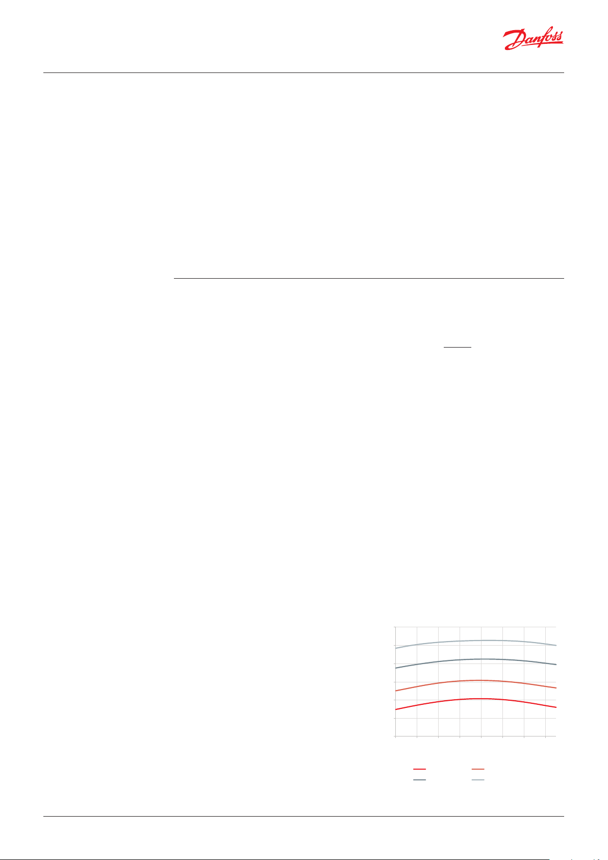
The optimal entrainment ratio is between
20 – 25% and the pressure lift between 5
– 14 bar. The pressure lift will be highest at
high ambient temperatures where we need
most of the ejector’s benefit. There is also a
dependency on suction flow super heat, as
laboratory experiments show that the highest
entrainment ratio is between 4 K and 12 K and
our recommendation is to take the flow from
the MT evaporators instead of common suction
line from MT evaporators and LT compressors
as the superheat can be higher depending on
LT/MT ratio. The high superheated gas in the
suction line will also result in reduced system
performance (COP).
Reduced COP can also occur if the LT mass flow
is relatively high in comparison to residual MT
evaporators’ flow, resulting in significantly high
MT compressors’ suction superheat and high
discharge temperatures at extreme ambient
conditions. To avoid this, an LT discharge
desuperheater can be applied or liquid injected
into the MT compressors’ suction line to maintain
acceptable superheat at those conditions.
Danfos
0.5
To the right is an example with different MT
evaporating temperatures (pressures) and ejector
suction superheat between 0 K and 15 K but
keeping constant:
• Temperature out of the gas cooler = 35 °C
• Pressure in the gas cooler = 90 bar(a)
• Pressure in the receiver = 38 bar(a)
0.4
0.3
0.2
0.1
0
0246810 12 14
Sucon Superheat
-10°C/26,5 bar(a) -8°C/28 bar(a)
© Danfoss | DCS (vt) | 2020.10 AB351943880096en-000101 | 3

Application Guide | High pressure lift ejector and liquid ejector systems
The high-pressure flow (ejector motive flow)
from the gas cooler enters the ejector which in
this system works like a high-pressure control
valve. The opening of the different ejectors is
controlled in order to maintain the high pressure
with the purpose of achieving optimum system
COP. The pressure/temperature curve and the gas
cooler outlet, contributing to optimum COP of
the system, is predefined and integrated in the
Danfoss pack controllers. In the ejector, energy
from the high-pressure side is used to entrain
gas from the suction side of the MT evaporators
and lifts it to the receiver. In the receiver, the gas
and liquid are separated and if the amount of
gas is higher than the minimum capacity of the
IT suction group, the controller should use IT
compressors instead of a gas bypass valve.
The benefit of the HP ejector is that it unloads
the MT compressors and enhances the IT
compressors by feeding gas that should be
compressed by the MT compressors. If we
consider the same design criteria for a variable
capacity IT compressor and its minimum mass
flow, the typical ambient conditions for engaging
the IT compressors will be lower than in a parallel
system without HP ejectors.
In well-designed IT suction group it will be
possible to start compressors at ambient
conditions from 15 – 20 °C, while comparing
to system with HP ejectors, and allowing the
receiver pressure fluctuation by using the IT
optimize function (one of the receiver control
options in AK-PC 782A pack controller), the
typical ambient conditions that can enable IT
compressors will be 5 – 7K lower. This control
strategy will contribute with more hours utilizing
the IT suction group during the year.
When using HP ejectors and the IT Optimize
function in regions with ambient conditions up
to 40 °C, the mass flow ratio between MT suction
and IT suction will be MT 35% / IT 65%. This will
give a significant reduction in annual energy
consumption compared to a standard booster
system, between 9 – 15%, depending on yearly
climate conditions and the ratio between LT and
MT load.
The energy consumption reduction is considered
without implemented Heat Recovery. When Heat
Recovery is applied in CO2 transcritical systems,
the pack controller will increase the pressure
in the gas cooler to above the critical point (74
bar(a)) in order to enable more heat rejection.
By doing this, the HP ejector will again have
a high potential to lift mass flow from the MT
evaporators to the receiver, like in warm ambient
conditions.
As for parallel compression, the oil management
of the parallel compressor enhanced with a highpressure ejector needs special attention because
the mass flow ratio for the parallel compressor
is high. However, it is possible to build a system
with safe oil return if the oil carry-over is
managed.
1.1 System design with a
High Pressure lift
ejector (HP)
Systems with High Pressure lift ejectors (HP
ejectors) are in many ways identical to parallel
compression systems, but the ejector enhances
the operation of the parallel compressors. The
ejector takes mass flow from MT compressors
and delivers it through the receiver to the IT
compressors. Consequently, the MT compressors
can be reduced in size and since the parallel
compressors are running at a higher suction
pressure the total swept volume will be reduced.
Oil return to the MT compressors are just as
on the standard system with gas bypass. The
oil/refrigerant mixture will even be richer on
oil. As there is no oil returning to the parallel
compressors through the suction line, extra
attention needs to be paid to this part of the oil
management system.
4 | AB351943880096en-000101 © Danfoss | DCS (vt) | 2020.10
Application Guide | High pressure lift ejector and liquid ejector systems
Design of MT/IT suction groups
To extract the maximum performance of a
system with ejectors it is important to be careful
when sizing the MT and IT suction group. For
the ejector and the overall system to yield a high
performance the receiver pressure should follow
the variable reference that as realized by the “IToptimize” reference mode for the IT compressor.
This however make it less trivial to size the
compressor groups (IT and MT) as it is important
to look at part load performance and not only
at the high design temperature and maximum
system load. Temperatures out of the gas cooler
between 15 – 20 °C and a part load operation
with a load of approximately 40 – 60% of the full
load condition (depending of the application)
should be considered. As the load on the IT
compressors are highly depended on the ejector
and the receiver pressure, they should be able to
cover a larger load span than a system without
ejectors, this makes it difficult to construct
an efficient system with only one parallel IT
compressor.
Parallel IT compressor capacity control
For MT and LT compressors suction groups, it
is important to have possibility to match the
actual compressor suction mass flow with the
system load. If there is no match, it will result
in suction pressure oscillations when cutting
in capacity steps (for increasing capacity) or
cutting out steps (for decreasing capacity). For
that reason, one or two Variable Speed Drives
(VSD) are used on leading compressors. When
considering the design of IT suction compressors,
having an as linear capacity control as possible
is even more important, because oscillations
in the receiver pressure control will affect both
the MT/LT evaporating pressure and the gas
cooler pressure, resulting in an unstable system
with compressors and fans running capacity
oscillations.
If cost is the driver, the performance at the
very warmest conditions can be sacrificed by
designing the compressors at part load condition
and then accept that the energy performance
at maximum load and maximum temperature
is not ideal. This is the same consideration as
with parallel compression systems. In case of
maximum load and maximum temperature,
the receiver pressure is allowed to increase and
therefore the entrainment ratio is decreasing,
leaving more gas to the MT compressors. In this
way the system can be cost optimized with only a
small penalty on energy.
The same design analogy can be applied to HP
ejectors by installing a High Pressure expansion
valve in parallel to it in order to cover the gas
cooler mass flow that cannot be taken by the HP
ejectors at very high temperature conditions. It
is possible to install more HP ejectors connected
in parallel, and in AK-PC 782A it is possible to
configure up to four ejector blocks in this way.
Higher receiver pressure oscillations can lead
to the IT compressors frequently reaching their
pump down limit. The pump down limit pressure
level will switch off IT compressors and start GBV
operation resulting in even more unstable system
operation. It is important to avoid long periods
with the MT and IT running large part of the
installed capacity in part load. At part load the
compressor is really inefficient. We have seen that
installing an ejector which removes load from
the MT and adds to the IT cause longer periods of
both MT and IT running part load causing overall
worse efficiency compared to not running with
the ejector. This is also an important argument
for splitting the capacity on more compressors.
Compressor suction group capacity control:
Example 1:
All compressors are same nominal size.
The first compressor has VSD control from 30 – 65 Hz. The rest are single step compressors.
Compressor index
Starting capacity
Gap between
compressor steps
1)
Compressor index represents capacity of each compressor as a relative number.
2)
Capacities represented as % of total suction line mass flow capacity.
1)
2)
2)
130 130 + 100 = 230
46% 26% 18% 14%
- 13% 9% 7%
130 + 100 + 100
= 330
130 + 100 +
100 + 100 = 430
© Danfoss | DCS (vt) | 2020.10 AB351943880096en-000101 | 5
Application Guide | High pressure lift ejector and liquid ejector systems
Example 2:
The first compressor has VSD control from 30 – 65 Hz. The rest are single step compressors, but 30%
smaller capacity compared to VSD nominal capacity at 50 Hz.
Compressor index
Starting capacity
Gap between
compressor steps
1)
Compressor index represents capacity of each compressor as a relative number.
2)
Capacities represented as % of total suction line mass flow capacity.
1)
2)
2)
130 130 + 70 = 200 130 + 70 + 70 = 270
46% 30% 22% 17%
- 0% 0% 0%
130 + 70 +
70 + 70 = 340
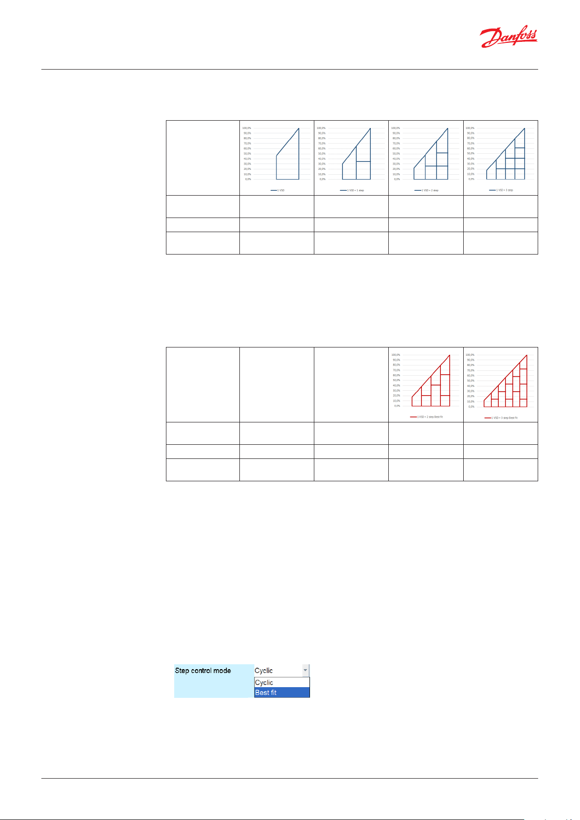
Example 3:
The first compressor has VSD control from 30 – 65 Hz. First single step compressor is 30% smaller
capacity compared to VSD nominal capacity at 50 Hz. Second and third double size of first single
step compressor. This configuration is applicable in systems with 1 VSD and 2 or more single step
compressors with Step control mode “Best fit”.
Compressor index
Starting capacity
Gap between
compressor steps
1)
Compressor index represents capacity of each compressor as a relative number.
2)
Capacities represented as % of total suction line mass flow capacity.
1)
2)
2)
- -
- - 17% 12%
- - 0% 0%
130 + 70 + 140
= 340
130 + 70 +
140 + 140 = 480
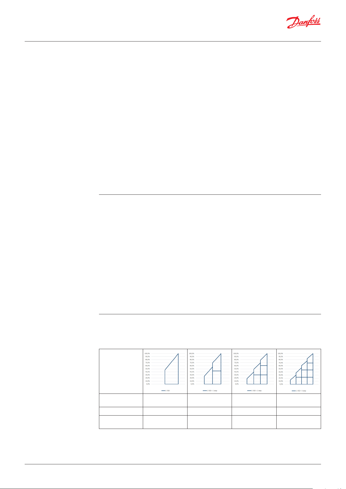
Conclusions:
• Example 1: More single step compressors will allow us to start the VSD compressor much earlier in
relation to total suction group capacity. Second, with more compressors there will be smaller gaps
between capacity control.
• Example 2: Using 30% smaller capacity single step compressors in comparison to nominal VSD
compressor, will result in linear capacity control (VSD control from 30 – 65 Hz). Drawback of such
configuration is less total capacity comparing to Example 1. because all single step compressors are
smaller.
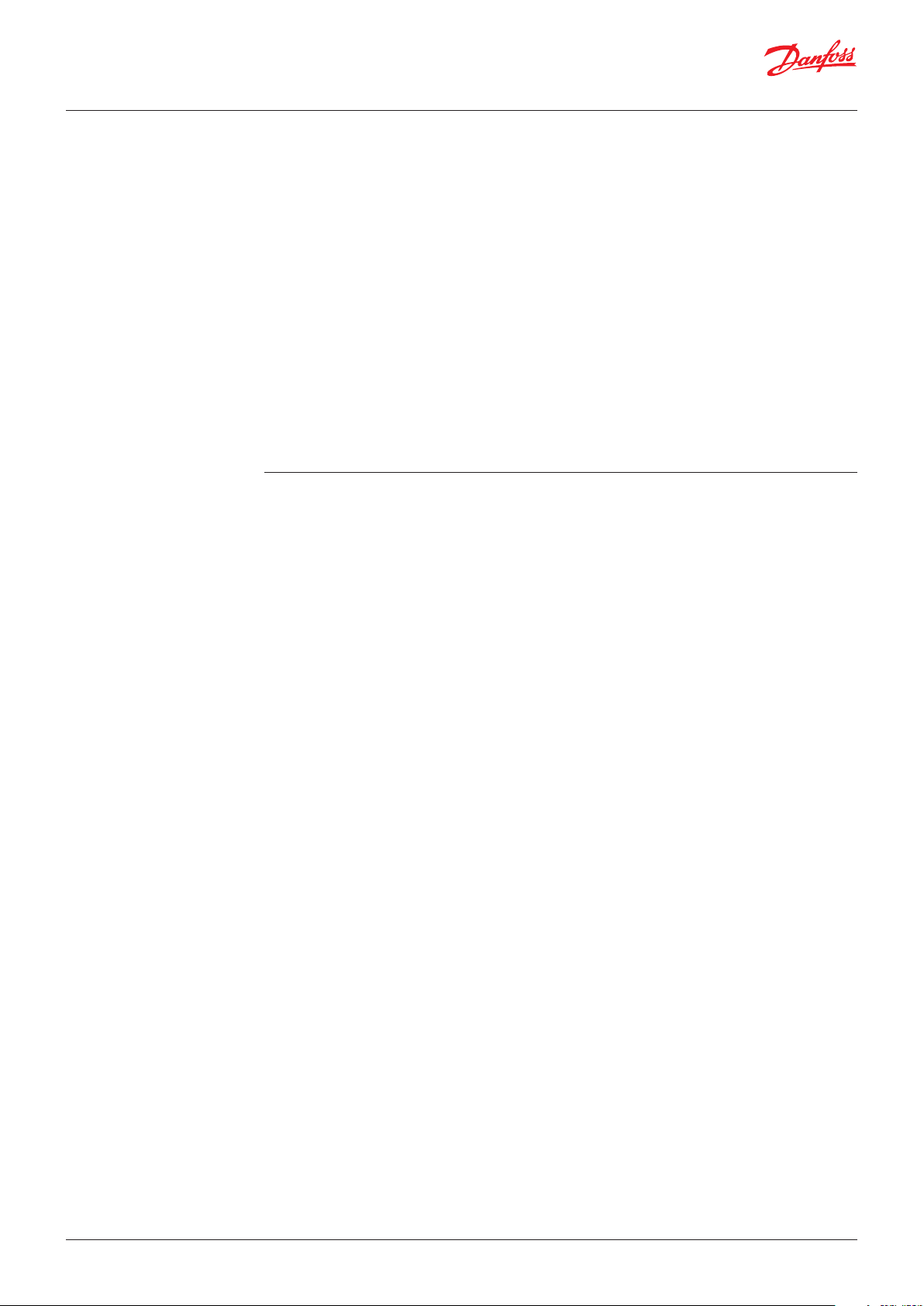
• In Danfoss pack controllers it is possible to select a “Best-fit” option which makes it possible to select
different sizes of single step compressors (Example 3.). To achieve linear control and higher capacity,
it is important that the first single step compressor has 30% less capacity than a VSD nominal capacity
at 50 Hz. Other bigger size compressors should not be larger than double size of the first single step
compressor. Having this kind of regulation, it is possible to achieve a higher total capacity comparing
to systems in Example 1 and 2.
• Examples 2 and 3 presents optimal sizing compressors to achieve linear control and maximum
overall capacity. In reality, it is good to have certain capacities overlapping in the area between two
steps it does not immediately trigger stating a new compressor and lower the speed on the VSD.
• When evaluating IT suction group design, to avoid system oscillations, it is extremely important to
have linear capacity control. By doing this we can utilize IT compressors and HP ejectors in optimum
way through the year and provide energy savings.
6 | AB351943880096en-000101 © Danfoss | DCS (vt) | 2020.10
Application Guide | High pressure lift ejector and liquid ejector systems
Single parallel compressor system design
The ideal solution is to have - as a minimum - two
IT parallel compressors and two MT compressors
with linear capacity control, but very often this
is not possible in smaller systems due to cost
reasons. Therefore, it is often seen that there
is only one parallel compressor. If this parallel
compressor is selected for maximum load, it
would give the optimum performance at high
ambient temperatures, but it will give very
poor performance in the medium ambient
temperature, where there are many operating
hours. The turning point, when the IT compressor
should start and the gas bypass valve should be
closed, is the condition where the minimum gas
mass flow IT compressor capacity (at minimum
speed) should match the gas mass flow in the
receiver. The challenge of selecting the right
compressor is even bigger considering that
lower ambient conditions (lower pressure in the
Maximum utilization of parallel compressor
system with HP ejectors design
In general, when selecting the compressors, the
following scenarios need to be considered:
• In a well-designed system with IT compressors
and HP ejectors the change-over between
the gas bypass valve and the IT compressors’
operation happen at ambient temperatures
between 12 – 15 °C. So below that turning
point, the minimum mass flow that the IT
compressors can handle needs to be added to
the MT compressor mass flow capacity. This is
not a huge issue as the gas quality is low and
the MT compressors will have more capacity
because the pressure in the gas cooler will be
low too.
• Receiver pressure: The system can be tuned
by optimizing the receiver pressure. This
functionality is embedded in the Danfoss AKPC 782A controller and is activated by selecting
Reference mode for the IT compressors
with the function “IT optimize”. At higher
temperatures out of the gas cooler (Sgc), the
receiver pressure is lifted gradually, depending
gas cooler), will result with higher compressor
capacity comparing to high extreme ambient
conditions.
As a result of the above considerations and
compromises, single parallel compressor systems
should be sized for the part load condition and
medium temperature conditions to achieve more
operation hours. With such configuration at full
load condition and high ambient temperature,
an IT compressor will run at full speed and the
suction pressure (receiver pressure) for the IT
compressor is allowed to rise to a determined
limit, causing the gas bypass valve to open
and release the surplus gas mass flow that
the IT compressor cannot handle to the MT
compressors. This will of course increase the load
on the MT compressors and should be taken into
account when designing the MT suction group.
on the MT suction and the gas cooler pressure.
If the receiver pressure is too low, savings will
be lower because the pressure is too close
to the MT suction pressure. A higher receiver
pressure also yields a smaller compressor due
to the higher suction pressure. Keep in mind
that a higher suction pressure also gives a
higher oil carry-over, so the compressor and
oil management need to be able to handle it.
There is a limitation on the receiver pressure
given by the manufacturer receiver design.
• Gas cooler mass flow: Due to mass flow
balances in systems with a HP ejector there
will be a higher mass flow through the gas
cooler than in parallel compressor systems
only. Depending how you control the pressure
in the receiver, the mass flow increase will
be different. If you run with the “IT optimize”
function at high ambient temperatures
increase will be up to 3%. If you run with
constant pressure in the receiver, the increase
at high ambient temperatures can be 6%
higher.
© Danfoss | DCS (vt) | 2020.10 AB351943880096en-000101 | 7
160.0
Pressure bar(a)
Enthalpy kJ/kg
80G449
s
80G450
160.0
Pressure bar(a)
Application Guide | High pressure lift ejector and liquid ejector systems
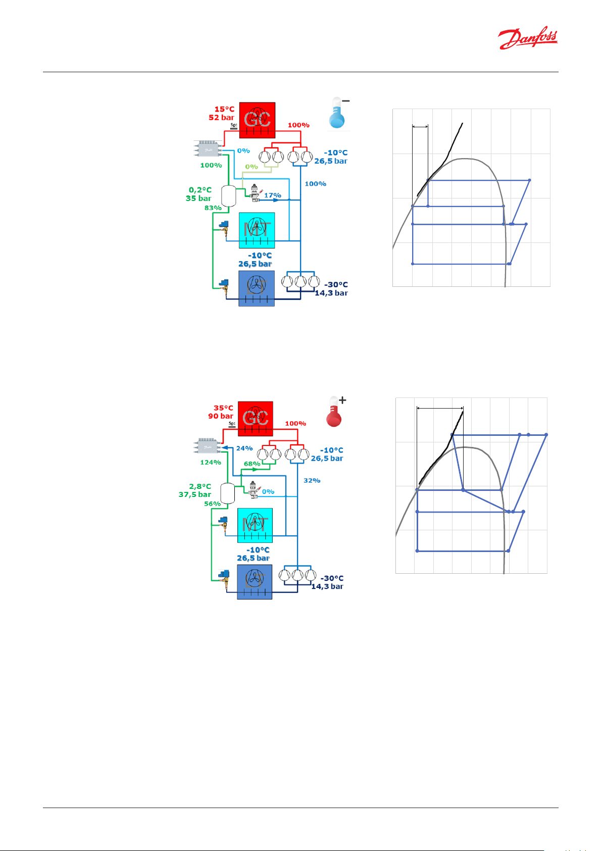
1.2 Example of system load
with a High Pressure lift
ejector
At above conditions (Po-MT/Prec/Pgc), the HP ejector is unable to make a necessary lift of 8.5 bar
and the amount of gas after the HP expansion is relatively small, so the system works as a standard
booster. To enable the ejector to provide a lift at specified Po-MT/Pgc conditions it will be necessary
to decrease the Prec pressure to 32 bar(a). This can be achieved using the receiver control mode “IT
optimize” and allowing lower minimum pressure reference in the receiver. There is also a feature for
keeping a minimum pressure difference between the receiver and the MT suction.
x = 17%
80.0
40.0
20.0
10.0
150.0 200.0 250.0 300.0350.0 400.0450.0 500.0550.0
Danfoss
x = 55%
80.0
40.0
20.0
10.0
150.0 200.0 250.0300.0 350.0400.0 450.0500.0 550.0
Enthalpy kJ/kg
In warm ambient conditions, the HP ejector has the ability to create a higher pressure lift. To optimize
system efficiency, we can gradually increase the receiver pressure and by doing this control the ejector
suction mass flow, keeping the entrainment ratio between 0.2 and 0.25. At above conditions, the
ejector suction mass flow is 24% of the motive mass flow (er = 0.24). Any gas after the HP expansion
and the ejector suction gas must be taken by the IT compressors.
Danfos
8 | AB351943880096en-000101 © Danfoss | DCS (vt) | 2020.10
Application Guide | High pressure lift ejector and liquid ejector systems
2. The Liquid Ejector (LE)
system – a general
description
2.1 Superheat control
including new Adaptive
Liquid Control (ALC)
The Liquid Ejector is designed for both standard
booster and parallel compression systems.
The working principle in the Liquid Ejector is
similar to the gas ejectors. The Liquid Ejector
is optimized to lift liquid from the suction
accumulator and returning it to the receiver. In
a Liquid Ejector system, the evaporators operate
with a very low superheat and a fraction of liquid
is returned to the suction accumulator, located
downstream of the evaporators. With the support
of an appropriate and intelligent case controller
the evaporator functions more efficiently at
a higher suction pressure. This enables the
suction pressure to be raised, thereby reducing
the energy consumption on the compressors.
Typically, the pressure in MT evaporators will
be increased, utilizing network Master Control
function Po optimization by 3.5 – 5 bar.
As the Liquid Ejector is powered by the work
which would have been otherwise lost, there is
no additional energy used to accomplish this.
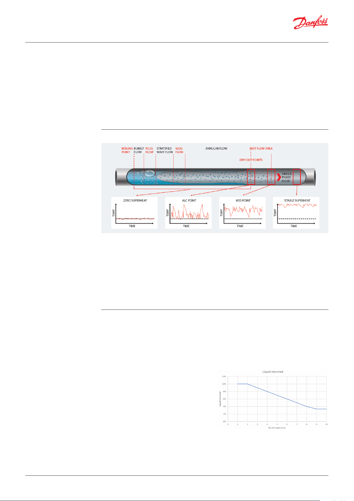
with an Adaptive Liquid Control (ALC) algorithm,
Superheat across an evaporator, represented with a single tube:
• Zero superheat can be measured in all of the
evaporator where fluid exists (until Dry-Out
point).
• The ALC point (Adaptive Liquid Control point)
can be found at the Dry-Out point on the
borderline between the Annular Flow area
and the Mist Flow area. With ALC the highest
evaporator efficiency is realized but with
droplets of refrigerant leaving the evaporator,
which is not a safe situation compressor wise,
so a suction accumulator must be applied.
The key to achieving the performance benefits
enabled by the Liquid Ejector is the use of the
Adaptive Liquid Control (ALC) algorithm available
in the newest generation of Danfoss case
controllers. This algorithm makes full use of the
entire surface of the evaporator, maximizing its
efficiency and operating with the lowest possible
superheat (close to 0 K).
The amount of liquid is difficult to estimate,
but a good estimate form experience is approx.
10% from the MT evaporators that are in liquid
mode (by using the Danfoss evaporator/case
controllers with the ALC functionality), also only
those evaporators which are maximum loaded
are in liquid mode, resulting in a reduced amount
of returned liquid. In general, the experience
shows that approx. 30% of the evaporators are
running in liquid mode at a given time, so the
amount of liquid returned is then approximately
10% x 30% = 3% of the total MT evaporators’
mass flow returning to the suction accumulator.
• The MSS point (Minimum Stable Superheat)
can be found on the borderline between the
Mist Flow area and the Single Phase Flow. With
MSS control the highest evaporator efficiency
is achieved while all liquid is evaporated and
only superheated gas is leaving the evaporator,
which is a safe situation compressor wise.
• Dry SH control. Stable superheat can be
measured when the superheat is higher than
the MSS point.
This assumption is valid for systems with many
evaporators of similar size like in a supermarket
application (more than 10). For systems like
cold storage plants with only a few evaporators
where some of them can represent a high ratio
in total MT evaporator capacity, the amount of
liquid returned as a percentage of the total MT
evaporator mass flow can be significantly higher.
Fig. 1: Returned liquid estimation of returned liquid as a
function of evaporators quantity.
© Danfoss | DCS (vt) | 2020.10 AB351943880096en-000101 | 9

Application Guide | High pressure lift ejector and liquid ejector systems
2.2 CO Adaptive Liquid
Management (CALM™)
The Danfoss solution for managing liquid in transcritical CO refrigeration applications is based
on enhanced versions of case controllers (AK-CC 550A, AK-CC55, AK-CC 750A), pack controller
AK-PC 782A, system managers of the range AK-SM 8xxA and Liquid Ejector. This solution is called
CO Adaptive Liquid Management (CALM) and represents a major step forward in refrigerant
management. CALM ensures integration between the case controls, pack controls and system
managers, enabling a safe operation in Liquid Ejector systems in all conditions.
To operate CALM™ it is necessary to set up the
system in the following way:
Pack Controller:
It is important to enable the Po optimization
feature on the MT suction line driven by a System
Manager AK-SM 8xxA. This Master Control
network feature constantly analyzes the most
loaded MT evaporator controllers and adjusts the
MT evaporation pressure in the pack controller
AK-PC 782A within specified limits.
Case (evaporator) Controllers with ALC
superheat control feature:
Modulated thermostat control should be
enabled. By using this feature, the amount of
liquid from the MT evaporators is limited as only
the most loaded will operate with ALC superheat
or at the minimum SH.
CALM™ solution:
1. If Liquid Ejectors are unable to take all the
liquid collected in the suction accumulator,
the liquid level will rise. When the liquid level
switch (ideally positioned 1/3 from the bottom
of the total height) indicates too high a level, a
digital signal triggers AK-PC 782A input.
2. Information about high level is transmitted via
a communication line to the System Manager
AK-SM 8xxA.
3. By using a communication line to the MT
evaporator controllers, superheat control will
switch from ALC to MSS (dry SH control) and
stop releasing liquid to the MT return line.
4. When the liquid level in the suction
accumulator drops to an acceptable level, the
system will send a signal to the evaporator
controllers to start the ALC superheat control
algorithm.
10 | AB351943880096en-000101 © Danfoss | DCS (vt) | 2020.10

Application Guide | High pressure lift ejector and liquid ejector systems
2.3 Suction accumulator
design
The suction accumulator is an important element in the system and very critical. It needs to be sized
so that it can handle the liquid returned in case the ejector stops working, and you must design the
system with oil return to the MT compressors.
Oil return can be done in following ways:
The simplest way is to have a U-tube in the suction accumulator with a hole at the lowest point where
an oil rich mixture will be returned to the compressor. The other option is to do the same but move
the hole into a solenoid valve or motor valve so the return can be controlled. For both principles it is
important that the suction port for the ejectors is higher than the oil return port. If this is not the case,
the ejector will take all the oil and there will be nothing to return to the compressors. It is important in
the design of the system to ensure that liquid trapped in the oil has evaporated before it reaches the
compressors.
Sizing the suction accumulator
There are several ways to estimate the size here is one proposal. To do the sizing, some
assumptions must be made:
• Worst case is that 3% of the flow returning
is the part where the system is emptied and
the last third is safety to ensure the liquid can
be separated. These distribution levels can of
course be made differently.
to the suction accumulator is liquid. If there
are less than 10 evaporators, this number
needs to be higher - see Figure 1. “Returned
liquid estimation as a function of evaporators
quantity”
• The time for dry out if we go from ALC
superheat mode to MSS superheat mode is set
to 10 min. Experiences from the field indicate
that it takes approx. 5 min for the system to dry
out, but it will depend on the installation.
• The suction accumulator is divided into 3 equal
size sections where the lower third is the part
Liquid separator with 3 equal levels
we use for normal operation, the second third
Example:
Based on the above information, liquid that is
returning can be calculated based on an MT
evaporator’s cooling capacity.
An MT cooling capacity of 100 kW will result in an
evaporator flow around 1540 kg/hr (depending
on the MT evaporating pressure and the pressure
in the receiver):
With the assumptions made above, the maximum
holding time is set to 10 min. That means that
the accumulator’s yellow zone should be able to
hold 47/6 = 7,8 kg and with some safety ~ 9 liters.
The total size of the suction accumulator should
be 100 kW with an MT system of approximately
3 x 9 = 27 liters. The suction accumulator CALM
operation level switch must be placed between
the green and the yellow zone (at 1/3 level) and
will send MT evaporators back to MSS superheat
mode (dry SH control). The safety level switch
that protects the MT compressors from liquid
slugging must be placed between the yellow and
the red zone.
© Danfoss | DCS (vt) | 2020.10 AB351943880096en-000101 | 11

oss
80G451
160.0
.0
Pressure bar(a)
80G452
160.0
Pressure bar(a)
Application Guide | High pressure lift ejector and liquid ejector systems
2.4 Example of system load
with Liquid ejector
The MT evaporation pressure is 4 bar higher than in a standard system due to the ALC superheat
control. The pressure difference between the receiver and Po-MT is 4.5 bar, enabling the Liquid Ejector
to lift also in colder ambient conditions. We can control the pressure difference Prec – Po_MT all year
round allowing LE operation.
80.0
40.0
20.0
10.0
150.0 200.0 250. 0 300.0350.0 400. 0 450.0 500. 0550
Enthalpy kJ/kg
Danf
80.0
40.0
20.0
10.0
150.0 200.0 250.0 300. 0 350. 0400.0 450. 0500.0 550. 0
Enthalpy kJ/kg
In warm ambient conditions all is the same as in cold ambient conditions. We could have a higher
pressure difference Prec – Po_MT, but not more than 7 – 8 bar as the LE is not able to create a higher
pressure lift.
Danfoss
12 | AB351943880096en-000101 © Danfoss | DCS (vt) | 2020.10

Application Guide | High pressure lift ejector and liquid ejector systems
3. System design with a
High Pressure lift ejector
(HP) and a Liquid Ejector
(LE)
This solution is meant for medium to large sized
commercial refrigeration systems with parallel
compression. The system will benefit from both
technologies - HP and LE - and it is the most
optimized solution with Danfoss ejectors. By
utilizing the ALC superheat control, there will
be zero or very low superheat from the MT
evaporators’ return line. The common suction line
to gas and liquid ejectors should be connected
in the same way as in an LE system, I.e. in the
suction accumulator’s lower part, but not at the
very bottom because that should be used for oil
return process.
In cold ambient conditions, a LE has the
possibility to lift liquid, allowing MT evaporators
to work at higher evaporation temperatures. By
also having HP ejectors operating and taking
liquid and gas from the suction accumulator, it is
possible to have a higher pressure in the receiver
in warm ambient conditions, enabling better
operating conditions for parallel compressors
HPV+Combi
The below outline shows a solution for medium
to large sized commercial refrigeration systems
with parallel compression. Combi ejector with
HP/LE combination all in one block.
under such conditions. A higher pressure in the
receiver will support the IT suction group in
becoming even more efficient.
The LT compressors’ discharge flow will be mixed
with residual flow from the MT evaporators,
resulting in a lower MT compressor superheat
than in standard booster systems.
To simplify the installation for medium sized
systems, Danfoss offers Combi ejectors - a
combination of HP and LE ejectors in one
component. There should be one suction line to
the Combi ejector block connected to the lower
part of the suction accumulator.
The ejectors (gas and liquid) control the gas
cooler pressure. Depending on the ejector
envelopes and the pressure conditions in the
system, the pack controller AK-PC 782A decides
which ejector cartridge that will open first: liquid
or gas ejector.
HPV+HP+LE
The below outline shows a solution for large
sized commercial refrigeration systems with
parallel compression. Separate HP and LE ejector
blocks.
© Danfoss | DCS (vt) | 2020.10 AB351943880096en-000101 | 13

oss
80G451
160.0
.0
Pressure bar(a)
Enthalpy kJ/kg
s
80G453
160.0
Pressure bar(a)
Enthalpy kJ/kg
Application Guide | High pressure lift ejector and liquid ejector systems
3.1 Example of system load
with Combi (HP + LE)
ejector
In cold ambient conditions the system benefits from CALM, resulting in a higher MT evaporation pressure.
80.0
40.0
20.0
10.0
150.0 200.0 250. 0 300.0350.0 400. 0 450.0 500. 0550
Danf
Danfos
80.0
40.0
20.0
10.0
150.0200.0 250.0300.0 350.0400.0 450.0500.0 550.0
When ambient temperatures become higher, the HP ejector has the capability to take gas + liquid. This
can create a higher pressure lift, which enables an increase in the receiver pressure for further optimization
of the IT suction group.
14 | AB351943880096en-000101 © Danfoss | DCS (vt) | 2020.10

Application Guide | High pressure lift ejector and liquid ejector systems
4. Configuration of the
AK-PC 782A
4.1 HP control
No matter if it is an HP-, LE-, or HP+LE ejector solution, setting the AK-PC 782A for supporting the
various ejector solutions is fully integrated in the controller. This will only impact the settings that
need to be made for the "HP control" and the selection of reference mode in the IT compressor
settings.
Under the HP control, the selection of the various supported ejector blocks is made. The ejector can
be selected either as pure HP-ejector block in combination with LE-ejector block or as combi blocks
– see figure below. Note that if more HP-ejector blocks are selected (“Number of block” larger than 1)
they will be operated in parallel and hence only one set of DOs is assigned. Hence, ejector 1 from the
parallel blocks should all be connected to the designated ejector DO point under the IO configuration.
Selecting multiple LE ejector blocks will result in individual DO points for each ejector cartridge.
Here it is also selected whether the CALM solution (MC Liq. Ctrl.) should be activated or not (see
explanations above).
The HP valve and the multi ejectors are all considered as actuators for controlling the gas cooler
pressure. This means that the HP controller needs to prioritize the actuation between the HP valve, HP
ejector and LE ejector.
The prioritization is roughly speaking done in two steps:
1. First, it is decided whether the HP valve or the multi ejector (HP+LE) is going to be used for
actuation – the multi ejector always has first priority, meaning that if more actuation is needed
and there is spare capacity available on the multi ejector (HP+LE), it will be actuated. Only when
no more ejector capacity is available, will the HP valve be activated. The figure below illustrates the
behavior during rising and falling gas cooler pressure:
The gas cooler pressure is controlled with
ejectors with a high-pressure valve or both (as
installed).
Ejectors only:
The ejector opening degree (required capacity)
increases when the pressure is too high and
closes when the pressure is too low.
High-pressure valve only:
The high-pressure valve opening degree
increases when the pressure is too high and
closes when the pressure is too low.
Ejectors and High-pressure valve:
The ejectors operate first, and the high-pressure
valve only comes into action when the ejectors
are fully utilized. The ejectors remain fully open
until the high-pressure valve has closed.
© Danfoss | DCS (vt) | 2020.10 AB351943880096en-000101 | 15

1
15
20
25
3
35
4000
45
50
Increasing cap preferred LE
LE 200 LE 400 HP 1 HP 2 HP 3 HP 4 HP 5 HP 6
oss
80G454
1
15
2
25
3
35
4
45
5
Increasing cap preferred HP
HP 1 HP 2 HP 3 HP 4 HP 5 HP 6 LE 20 0 LE 400
Danfoss
80G455
Application Guide | High pressure lift ejector and liquid ejector systems
2. The second step of prioritization is between
the HP ejector and the LE ejector. This
prioritization is done based on the ejector
maps. The figure to the right shows the areas
in which the preferred ejector type is the
HP ejector or the LE ejector respectively,
depending on the pressure lift (Plift=Prec-P0MT) and the pressure drop (Pdrop=Pgc-Prec).
Note: the max pressure lift for the LE ejector
has been increased to 10 bar in PC782A v.2.71
from 8 bar in previous versions.
For details in switching patterns, please see the graph below.
The ejectors steps are combined to form a capacity as close as possible to the requested capacity
by the control. In case the same capacity can be obtained by combinations of liquid and gas ejector
respectively the controller will:
- For increasing capacity demand open for the prioritized ejector type
- For decreasing demand close for the lowest prioritized ejector type
See also the figures below for HP 3875 and LE 600:
00
00
00
000
00
00
00
000
500
0
135791113151719212325272931333537
Danf
000
00
000
00
000
00
000
00
000
500
0
1357911131517192123252729313335
All the standard settings around the gas cooler i.e. fan control, high-pressure curve etc. still applies
when running with ejectors, however there are a couple of dedicated settings that only apply for the
ejector:
1. When controlling the pressure using
the ejector block, the ejector capacity is
modulated in steps like indicated in the
figures above. Practically, this means that the
HP controller is likely to be switching between
two steps to maintain a certain pressure
reference. To avoid too frequent switching,
a neutral zone (Pgc neutral zone) on top of
the high-pressure reference is implemented.
This allows the pressure to drift (default 3
bar) above the pressure reference without
stepping up in ejector capacity, hence
reducing the number of switches of ejector
capacity.
2. When the ejectors are actively controlling the
gas cooler pressure, the PI-controller tuning
factors (Kp or Tn) are set separately.
3. To enable the CALM™ solution it is necessary
to start the Master Control feature “MC Liq.
c t rl .”
4. If the condition of being inside the ejector
envelopes to enable CALM™ wants to be
avoided, you can select feature “MC Liq.
discard map” to “No”.
16 | AB351943880096en-000101 © Danfoss | DCS (vt) | 2020.10

Application Guide | High pressure lift ejector and liquid ejector systems
5. “MC liq.ctrl. via DO” is using Digital Output on
AK-PC 782A to send a signal to the evaporator
controllers’ bypassing network unit AK-SM.
Note that if a DO is used, be careful to make
the connections such that if the cable is
removed the ALC will be stopped. By default,
the ALC is enabled when the DO is closed.
6. It is possible to disable ejectors by dedicated
DI (Digital Input).
4.2 Receiver control
For plant types without IT compressors but with
e.g. an LE ejector, it is important to configure
a receiver setpoint, which secures that the
operating point of the ejector stays inside the
ejector map (see figure in previous section). For
the LE ejector the pressure lift should not be
higher than around 9 – 10 bar (for AK-PC 782A
version 2.71 and up) to avoid losing LE ejector
efficiency. This means that if e.g. the ToMT = -10
°C ~ 25.5 bar, the receiver setpoint “Prec setpoint”
should not be set higher than around 25.5+7 =
32.5 bar to ensure that there is always lift from
the LE ejectors.
For systems with IT compressors it is possible to
select between various reference modes for the
IT compressor. It is generally recommended to
use the “IT-Optimize”. This will strive to adjust the
setpoint for the IT compressor to optimize the
system efficiency – however it does not ensure
that the maximum pressure lift for the ejectors
are obeyed. To ensure the maximum pressure lift
stays inside the ejector envelope, the maximum
IT reference (P-IT max. reference) should be
limited.
To give an example: assuming that a system is
running with HP ejectors, the maximum pressure
lift is around 15 bar. Further assume that the
reference for the To-MT is -8 °C (~27 bar), then the
maximum receiver pressure reference (P-IT max.
reference) should be limited to 27+15 = 42 bar.
Same considerations should be done when
working with Liquid Ejectors only but minimum
and maximum references need to be aligned.
Note: When running in the IT-Optimize mode
the reference to the receiver can be as high as
the bottom of the receiver P-band, if not limited
by P-IT max. reference. This means that if the
neutral zone of the IT-compressor overlaps with
the P-band, then the receiver valve is forced open
before the second IT compressor is started. This
can result in the second to last IT-compressors
not activating when needed the most. (This
is an issue for systems with two or more ITcompressors).
To avoid this, the following settings are
recommended:
P-IT min reference = Prec setpoint (used for Vrec –
Gas Bypass Valve)
P-IT max reference < Prec max – Prec max Pband
– NZ/2+1 = 55 -3 - 3/2+1 = 51.5 bar
© Danfoss | DCS (vt) | 2020.10 AB351943880096en-000101 | 17

Application Guide | High pressure lift ejector and liquid ejector systems
4.3 CALM™ set-up in Pack
Controller AK-PC 782A
For systems with HP and/or LE ejectors it is
possible to utilize the CALM™ solution (see
explanation of the CALM™ function in a previous
section). Under the HP Control, the CALM™ can
be selected by enabling the “MC. Liq.ctrl.” The
“MC. Liq. Ctrl” is a safety control feature that
monitors the operation of the ejectors and of the
liquid level in the suction accumulator to ensure
safe operation without liquid getting back to the
compressors. There are several criteria for when
ALC is allowed:
• If no ejectors are configured, then ALC is not
allowed.
• In the suction accumulator (a receiver in the
suction line of the MT compressors) there
MUST be a level switch. When the liquid hits
this level switch or there is an error on the
switch, then ALC is NOT allowed for the next
30 minutes The countdown timer is set to 30
minutes every time it hits this condition. This
time should be enough to empty the suction
accumulator.
• If the ejectors are not able to lift (meaning
that no ejectors are operated inside the map
of according to ejector type) or no ejector are
open, then ALC is not allowed for the next two
minutes. This is to prevent ALC at uncertain
ejector pumping capacity. The countdown
timer returns to two minutes every time it is
outside the map or the last ejector is closed.
• Both timers must be 0 before ALC is allowed.
• If at least one ejector is active and operated
inside the ejector map, then it is expected to
be able to pump/lift liquid and therefore ALC is
allowed if the former criteria is fulfilled.
Following “MC liq.ctrl status” can be observed:
• Timer
• No lift
• Permitted
• High level
To check whether the ejectors are operated
inside their maps, following the pressure drop
(Pdrop) and pressure lift (Plift) is used.
Pdrop = Pgc reference - Prec reference*
Plift = Prec reference* - PoMT
Where Prec reference* = Max (Prec reference, Prec
filtered 60 sec). This means that if the measured
Prec is above its reference for approximately 60
sec then this will be used in the calculations of
Pdrop and Plift.
18 | AB351943880096en-000101 © Danfoss | DCS (vt) | 2020.10

Application Guide | High pressure lift ejector and liquid ejector systems
4.4 I/O Configuration
When the AK-PC controller has been configured
for control of an HP/LE ejector system, several
Digital outputs and Digital inputs need to be
configured.
This includes outputs used for controlling the
Multi Ejector (I/O configuration Digital outputs)
and if using the CALM™ solution input for Suction
accumulator level switch (I/O configuration
Digital Inputs).
The outputs used for controlling the smallest HP
ejectors and LE ejectors must be of the SolidState Relay type (SSR).
In this example the four smallest ejectors are
configured to be controlled by the four SSR
outputs available on the AK-PC 782A controller
(IO points 1-12 to 1-15).
If multiple HP ejector blocks are selected
(“Number of block” larger than 1), they will be
operated in parallel and only one set of DOs is
assigned. Therefore, Ejector 1 from the parallel
blocks should all be connected to the same
designated ejector DO point under the IO
configuration. If selecting more LE ejector or
combi blocks each liquid ejector cartridge needs
individual DO in IO configuration.
4.5 CALM™ set-up in System
Manager AK-SM 8xx
In the pack controller the decision whether to allow ALC is made, which means that the decision
should be communicated to the case controllers via the System Manager. For this feature there are
two options: either hardwired via a pack controller DO (selecting “MC.Liq.ctrl. via DO” explained at the
end of chapter 4.1 HP control) or via the fieldbus.
After configuring MT and LT suction groups, proceed to menu Control Refrigeration Suction.
Select MT Suction Group and then enable following Master Control functions:
• Suction Optimization
• Adaptive Liquid Management (this feature is only available for AK-CC55 evaporator controllers)
© Danfoss | DCS (vt) | 2020.10 AB351943880096en-000101 | 19

Application Guide | High pressure lift ejector and liquid ejector systems
For other evaporator controllers with ALC superheat control (AK-CC 550A, AK-CC 750A but also
AK-CC55), it is possible to set up the CALM™ feature manually via Custom Schedule.
1. Import the right controlling parameter from AK-PC 782A to the AK-SM - “MC liq.ctrl allowed” - so it
can be used in the Custom Scheduler
AK-SM 782A sw 2.08, 2.12, 2.21 AK-SM 782A sw 2.65 and higher
2. Configure Custom Schedule under menu Control Refrigeration Schedules in following way
3. Select device parameter in the evaporator controller:
4. Select the controllers that should receive “ALC MC Liq.ctrl” command:
20 | AB351943880096en-000101 © Danfoss | DCS (vt) | 2020.10

Application Guide | High pressure lift ejector and liquid ejector systems
5. Evaporator controllers’ status for AK-CC 550A and AK-CC55, depending on SH control mode:
6. Setup “Thermostat mode” on the MT evaporators to “Modulating”
7. In AK-SM 8xx you can observe the ejector operation under Detail menu HP control and drill down
the menu Ejector control. When using the Service tool, the second tab under “HP control” shows the
same measurements / statuses.
© Danfoss | DCS (vt) | 2020.10 AB351943880096en-000101 | 21

32F870.10
Application Guide | High pressure lift ejector and liquid ejector systems
5. What is an ejector, and
how does it work?
An ejector is a device that utilizes the energy
from the high-pressure work. The ejector
converts the high-pressure potential energy in
the motive flow (primary) into kinetic energy,
drawing a flow from the suction port (secondary
flow).
The process, shown on the right, is driven by the
high CO pressure gas leaving the gas cooler.
The gas enters the ejector at the high-pressure
port (PH) and flows through the throat, causing
the flow to accelerate. At the exit of the ejector
nozzle, the gas is at supersonic speed, creating
a low pressure (PS). As low pressure (PS) is lower
than the pressure (PL) at the suction (secondary)
nozzle, CO is flowing from the suction port into
the ejector. The two flows are mixed in the mixing
chamber and the pressure is gradually increased.
The flow finally enters the diffuser at the end of
the ejector. Because of the conic diffuser shape,
the flow gradually slows down, and the pressure
Danfoss Multi Ejector design
All ejectors in the Danfoss portfolio have a highpressure inlet for CO gas coming from the gas
cooler, a suction inlet from MT suction and an
outlet for returning the gas and liquid to the
receiver.
The coils activating the individual ejectors are
available from 110 – 230 V, 50 and 60 Hertz.
The Multi Ejectors High Pressure and Combi are
delivered with three pressure transmitters, used
for pressure control in the pack controller.
Each block has a variable number of ejectors of
different sizes mounted vertically.
Multi Ejectors HP are available with 4 to 6 high
pressure ejectors. Liquid Ejectors is available
is increased. This means that the kinetic energy
of the flow (velocity) is converted to potential
energy (pressure). After leaving the diffuser,
CO is at a higher pressure (PD) than the suction
pressure (PL).
with 1 to 2 liquid ejectors. But Multi Ejectors
Combi are available with 4 to 5 high pressure
ejectors and 1 to 2 liquid ejectors. The capacity
demand is matched by using different numbers
and combinations of ejectors. The characteristics
of the ejectors remain the same no matter how
many ejectors are in use. On each individual
ejector a built-in non-return valve prevents
backflow, removing the need for external check
valves in suction lines.
Each individual ejector and the strainer are easily
serviced by simply removing the four mounting
screws, using a flat screwdriver to lift the ejector
or strainer, and pulling it out of the block. The
strainer can easily be taken apart for cleaning or
replacement.
Coils adv. (230 V DIN and 120 V UL all 50 – 60 Hz)
HP Pressure
transmitter
MT Pressure
transmitter
Receiver pressure
transmitter
All pressure transmitters MBS 8250 with round Packard, radiometric output and 7/16-20 UNF (same type as CCMT valves)
HP inlet from
Suction inlet from
MT evaporator
Danfoss
Strainer
gas cooker
Outlet to
receiver
22 | AB351943880096en-000101 © Danfoss | DCS (vt) | 2020.10

s
80G456
10
15
20
25
Increasing cap preferred LE
LE 200#1 LE 200#2 HP 1 HP 2 HP 3 HP 4
s
80G457
10
15
20
25
Increasing cap preferred HP
HP 1 HP 2 HP 3 HP 4 LE 200#1 LE 200#2
Application Guide | High pressure lift ejector and liquid ejector systems
Multi Ejector Capacity Control
Multi Ejector capacity control is achieved through
a binary coupling of various capacities of a
number of ejectors. The Multi Ejector Combi, for
example, comes in three versions. The version
with four high-pressure ejectors and two liquid
ejectors has high-pressure ejectors providing
125 kg/h, 250 kg/h, 500 kg/h, 1000 kg/h and two
liquid ejectors each providing 200 kg/h of motive
mass flow.
There are also two versions with five highpressure ejectors and one liquid ejector. Both
versions provide the same high-pressure capacity
which consists of ejectors giving 125 kg/h, 250
kg/h, 500 kg/h, 2 x 1000 kg/h of motive mass
flow, but depending on the version there are two
sizes of liquid ejectors providing 200 kg/h or 400
kg/h of motive mass flow.
This allows to modulate high pressure capacity
in 18 steps between 0 and 2875 kg/h in 125 kg/g
steps and liquid capacity in two steps between
0 and 400 kg/h in 200 kg/h steps. But if more
capacity is required, a second Multi Ejector can
be added which will be controlled parallel to the
first one.
Liquid ejectors are activated when there’s some
liquid in MT suction accumulator. They might
operate alone when high-pressure ejectors are
not activated or in parallel to the high-pressure
ejectors. One line is used to supply liquid and gas
from suction accumulator to low-pressure inlet
of Multi Ejector. The liquid ejectors take in the
liquid, whereas the gas is taken by high-pressure
ejectors.
00
00
00
00
500
0
12345678910 11 12 13 14 15 16 17 18 19 20
Capacity regulation with four HP ejectors and two LE
ejectors where LE are preferred.
Multi Ejector High Pressure
Danfos
00
00
00
00
500
0
123456789101112131415161718
Capacity regulation with four HP ejectors and two LE
where HP ejectors are preferred.
Danfos
© Danfoss | DCS (vt) | 2020.10 AB351943880096en-000101 | 23
Multi Ejector Liquid Ejector
Multi Ejector Combi

Application Guide | High pressure lift ejector and liquid ejector systems
The liquid ejectors and/or largest ejectors are placed closest to the connectors.
How does the Multi Ejector solution work?
The flow enters the Multi Ejector through the strainer in front of the high-pressure inlet. The AK-PC
controller decides which ejector is activated to meet the requested capacity. Through the open nozzle,
the high-pressure flow is transformed into high velocity flow. The high velocity creates a very low
pressure, making the suction of the MT possible. The flow from the MT suction inlet enters the ejector
through the check valve, mixing with the high velocity flow. The mixed flow is slowed down in the
diffuser part of the ejector, transforming the velocity to pressure. From here the mixed flow is lead to
the receiver and thereby recovering a part of the expansion work.
24 | AB351943880096en-000101 © Danfoss | DCS (vt) | 2020.10

10
HP 3875 OD% at constant load
II+H P Prec Opt II+HP Prec 35bar II+H P Prec 36 II+HP Pr ec 37
80G458
Application Guide | High pressure lift ejector and liquid ejector systems
6. Coolselector®2
Selecting components
6.1 HP ejector selection On the diagram to the right there is an example of
how the HP ejector Opening Degree (OD%) changes
by keeping constant cooling evaporators’ load at
different Gas cooler Outlet temperatures (Sgc).
Notice two peeks around 26 – 27 °C and 35 – 36 °C.
There is also a dependency in how it is controlled
pressure in the receiver. By keeping the pressure
in the receiver constantly at 35 bar(a), the peak
load for the HP ejector is at 36 °C. If the pressure is
controlled with the “IT Optimize” feature, the load
peeks are at 27 °C and 35 °C.
By using a Gas cooler Outlet temperature at 35 °C
and an Optimal gas cooler pressure around 90 bar(a)
is a good starting point for selecting HP ejectors.
0.0%
95.0%
90.0%
85.0%
80.0%
75.0%
70.0%
65.0%
60.0%
22 24 26 28 30 32 34 36 38 40
Outlet temperature Sgc (°C)
Danfoss
1. 2. 3.
m_motive : Gas Cooler / motive mass flow
m_suction : Ejector suction mass flow
m_comp_MT : MT compressors’ mass flow
m_comp_IT : IT compressors’ mass flow
er : entrainment ratio
© Danfoss | DCS (vt) | 2020.10 AB351943880096en-000101 | 25
msuction 843
er = =
mmotive
3419
Operating envelope:
= 0.25

Application Guide | High pressure lift ejector and liquid ejector systems
6.2 LE ejector selection
In section 2.1 “System design with Liquid ejector
(LE)”, there is an explanation about the amount
of returned liquid from the MT evaporators
depending on the application. In a typical
supermarket application with more than 10
evaporators we can assume that the amount of
liquid returned is 3% of the total MT evaporators’
mass flow. The default value in Coolselector®2 is
3%. If the application is different, it is necessary to
For LE the most critical condition is cold ambient
and related to this minimum pressure in the gas
cooler. The most critical condition is minimum
gas cooler outlet temperature and related
optimum pressure in the gas cooler. If the gas
cooler pressure is kept at e.g. 50 bar and the
temperature out of the gas cooler is lowered,
then the LE will have even better performance
than on optimal COP curve.
change this value in following preferences.
1. 2.
3.
The required suction mass flow calculated as percentage of the MT evaporator mass flow:
m_motive : motive mass flow though Liquid ejector
m_suction : Ejector liquid suction mass flow
m_suction_required : calculation based on assumption of 3% of m_evap_MT mass flow
er : entrainment ratio
msuction 168
er = =
mmotive
631
= 0.27
Operating envelope:
26 | AB351943880096en-000101 © Danfoss | DCS (vt) | 2020.10
Application Guide | High pressure lift ejector and liquid ejector systems
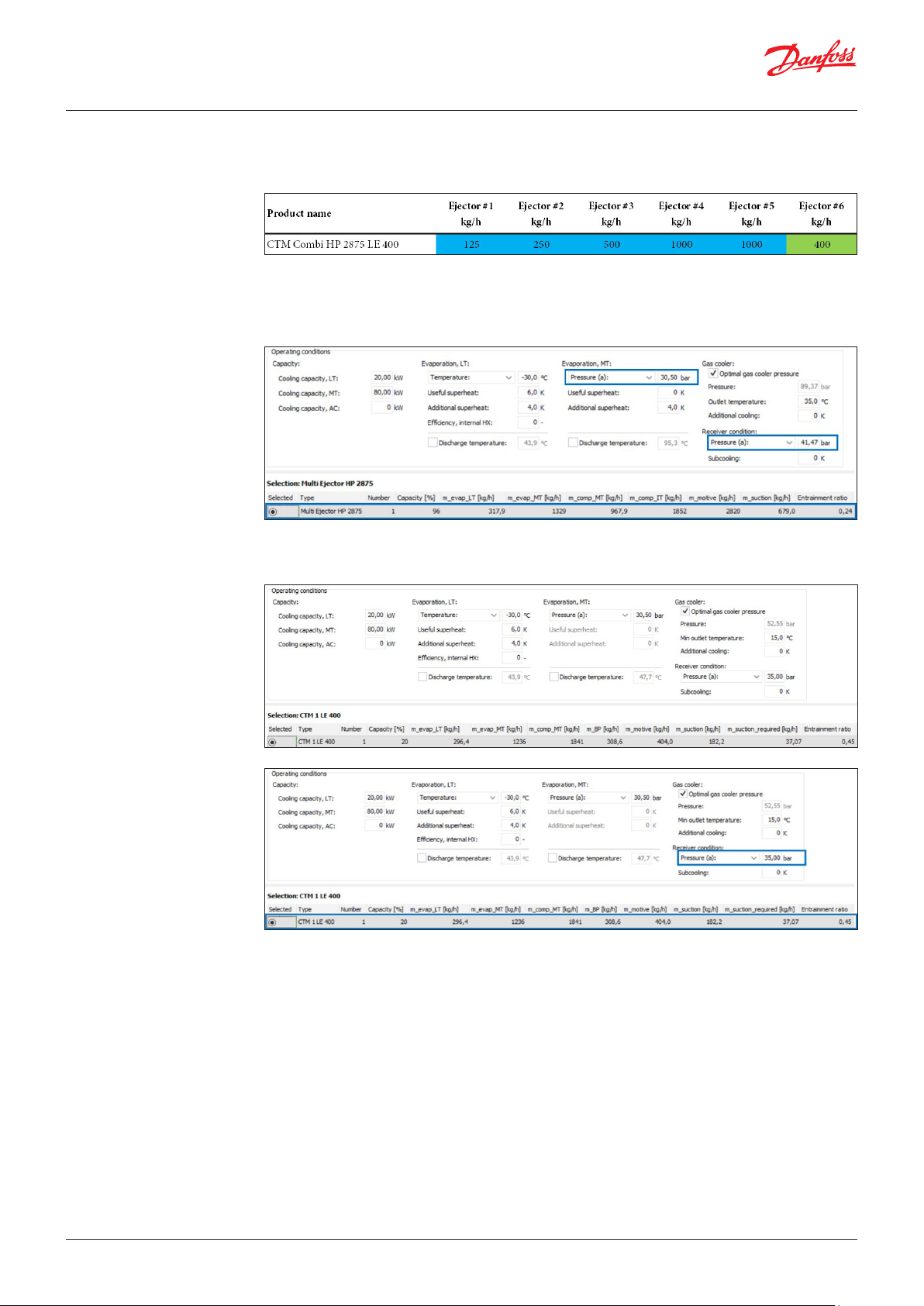
6.3 Combi ejector selection
(HP+LE)
As in Coolselector®2 there is no direct selection for Combi ejector. The selection will be done
separately using an HP and LE module. The below example shows a selection for Combi HP2875 LE400
consisting of 5 x HP ejectors and one LE 400.
The MT evaporating pressure will be higher because of ALC and CALM leading to 0 K Useful superheat.
The receiver pressure level is optimized for the best system efficiency. The HP ejector should fulfill
the necessary motive flow for the given capacity load and gas cooler conditions at high ambient
conditions.
Liquid ejectors should be capable to lift liquid in cold ambient conditions, but with lower receiver
pressure.
© Danfoss | DCS (vt) | 2020.10 AB351943880096en-000101 | 27
7. Multi Ejector Solution™
Danfoss offers a wide range of market leading Multi Ejectors. Including 3 MBS 8250
sensors and additional coils and LED plugs are needed.
CTM Multi Ejector - High Pressure (optimizing parallel compression systems):
• Energy consumption reductions up to 9% annually in warm climates compared to
parallel compression, and by up to 17% compared to booster systems.
• Available ejector types: HP 1874 (4 ejectors), HP 2875 (5 ejectors), HP 3875 (6 ejectors).
• It is recommended for stores with a refrigeration load in the range of 35 – 140 kW.
CTM Multi Ejector - Liquid Ejector (optimal evaporator utilization and efficient
compressor protection):
• Energy consumption can be lowered by 2 – 12% annually in any climate compared to
regular booster systems.
• Available ejector types: LE 200 (1 ejector), LE 400 (1 ejector), LE 400 (2 ejectors),
LE 600 (2 ejectors), LE 800 (3 ejectors).
• It is recommended for stores with a refrigeration load in the range of 25 – 480 kW.
CTM Multi Ejector - Combi HP/LE (optimizing parallel compression systems and
evaporator utilization and efficient compressor protection):
• Enables 15 – 35 % savings on compressor swept volume, compared to booster
systems.
• Available ejector types: Combi HP 1875 LE 400 (6 ejectors),
Combi HP 2875 LE 200 (6 ejectors), Combi HP 2875 LE 400 (6 ejectors).
• It is recommended for stores with a refrigeration load in the range of 35 – 120 kW.
CTM Multi Ejector - Low Pressure (optimizing booster system energy consumption):
• Energy consumption can be lowered by up to 15% compared to a booster system.
• Available ejector types: LP 935 (4 ejectors), LP 1435 (5 ejectors), LP 1935 (6 ejectors).
• It is recommended for stores with a refrigeration load in the range of 18 – 72 kW.
Pack controller - AK-PC 782A
Danfoss offers a wide range of market leading Pack Controllers.
Being the flagship and best in class controller for transcritical CO pack controls,
the AK-PC 782A offers the highest possible efficiency with the Multi Ejector.
Coolselector®2 - Transcritical High Pressure Application
Helps you optimize energy consumption and increase efficiency in any system. Run
unbiased calculations based on a set of operating conditions — such as cooling
capacity, refrigerant, evaporation, and condensation temperature — and then select
the best components for your design.
Check out the new Transcritical High Pressure Application area.
© Danfoss | DCS (vt) | 2020.10 AB351943880096en-000101 | 28
ADAP-KOOL®
 Loading...