

Danfoss HHP015T4LP6, HHP015T5LP6, HHP019T4LP6, HHP019T5LP6, HHP021T4LP6 Application guide
...Page 1
Application guidelines
Danfoss Heat Pump scroll
compressors, HHP-Series
50Hz - R407C
http://cc.danfoss.com
Page 2

Page 3

Page 4

Application Guidelines
Content
Scroll compression principle ........................................................................................... 6
Scroll compressor components ................................................................................................................................. 6
The scroll compression process .................................................................................................................................7
Performance ..................................................................................................................................................................... 7
Compressor model designation ...................................................................................... 8
Nomenclature .................................................................................................................................................................. 8
Label .................................................................................................................................................................................... 8
Technical specications ................................................................................................... 9
50-Hz data ......................................................................................................................................................................... 9
Performance table .......................................................................................................................................................... 9
Dimensions ...................................................................................................................... 10
HHP015-019-021-026 ...................................................................................................................................................10
HHP030-038-045 ............................................................................................................................................................11
Electrical data, connections and wiring ......................................................................... 12
Motor voltage .................................................................................................................................................................12
Wiring connections .......................................................................................................................................................12
IP rating .............................................................................................................................................................................13
LRA (Locked Rotor Amp) .............................................................................................................................................13
MCC (Maximum Continuous Current) ....................................................................................................................13
Max Oper. A (Maximum Operating Amp) .............................................................................................................13
Winding resistance ........................................................................................................................................................13
Electrical connections .................................................................................................................................................. 13
Nominal capacitor value .............................................................................................................................................14
Internal motor protection ...........................................................................................................................................14
Phase sequence and reverse rotation protection ..............................................................................................14
Voltage imbalance ........................................................................................................................................................14
Approvals and certications ........................................................................................... 15
Approvals and certicates ..........................................................................................................................................15
Pressure equipment directive 97/23/EC ................................................................................................................15
Low voltage directive 73/23/EC, 93/68/EC ...........................................................................................................15
Internal free volume .....................................................................................................................................................15
Operating conditions ...................................................................................................... 16
Refrigerant and lubricants ..........................................................................................................................................16
Motor supply ...................................................................................................................................................................16
Compressor ambient temperature ..........................................................................................................................16
Application envelope ...................................................................................................................................................17
R407C ................................................................................................................................................................................17
Maximum discharge gas temperature ...................................................................................................................17
High and low pressure protection ...........................................................................................................................18
On/o cycling (cycle rate limit) .................................................................................................................................18
4 FRCC.PC.017.A2.02
Page 5

Application Guidelines
Content
System design recommendations .................................................................................. 19
General ..............................................................................................................................................................................19
Essential piping design considerations .................................................................................................................19
Refrigerant charge limit ..............................................................................................................................................20
Reversible heat pump systems .................................................................................................................................20
Crankcase heater............................................................................................................................................................22
Minimum sump superheat ......................................................................................................................................... 22
Loss of charge protection ...........................................................................................................................................22
Oil level checking and top-up ................................................................................................................................... 22
High pressure ratio ........................................................................................................................................................22
Preventing liquid ood back .....................................................................................................................................22
Testing for excessive liquid ood back ..................................................................................................................22
Water utilising systems ................................................................................................................................................22
Sound and vibration management ................................................................................ 23
Running sound level .....................................................................................................................................................23
Sound generation in a refrigeration system / air conditioning system .....................................................23
Compressor sound radiation .....................................................................................................................................23
Mechanical vibrations ..................................................................................................................................................23
Gas pulsation ...................................................................................................................................................................23
Installation ....................................................................................................................... 24
System cleanliness.........................................................................................................................................................24
Compressor handling and storage ..........................................................................................................................24
Compressor mounting .................................................................................................................................................24
Compressor holding charge ......................................................................................................................................24
Tube brazing procedure .............................................................................................................................................. 24
Brazing material .............................................................................................................................................................24
Vacuum evacuation and moisture removal .........................................................................................................25
Liquid line lter driers ..................................................................................................................................................26
Refrigerant charging .....................................................................................................................................................26
Insulation resistance and dielectric strength ......................................................................................................26
Compressor replacement after motor burn out .................................................................................................26
Ordering information and packaging ............................................................................ 27
Packaging .........................................................................................................................................................................27
Packaging details ...........................................................................................................................................................27
Ordering information and packaging ....................................................................................................................27
Spare parts & accessories ................................................................................................ 28
Run capacitors for PSC wiring ...................................................................................................................................28
Rotolock adaptor set ....................................................................................................................................................28
Rotolock adaptor ...........................................................................................................................................................28
Crankcase heater............................................................................................................................................................28
Discharge temperature protection .........................................................................................................................29
Lubricant ...........................................................................................................................................................................29
Mounting hardware ......................................................................................................................................................29
5FRCC.PC.017.A2.02
Page 6
Application Guidelines
Scroll compression principle
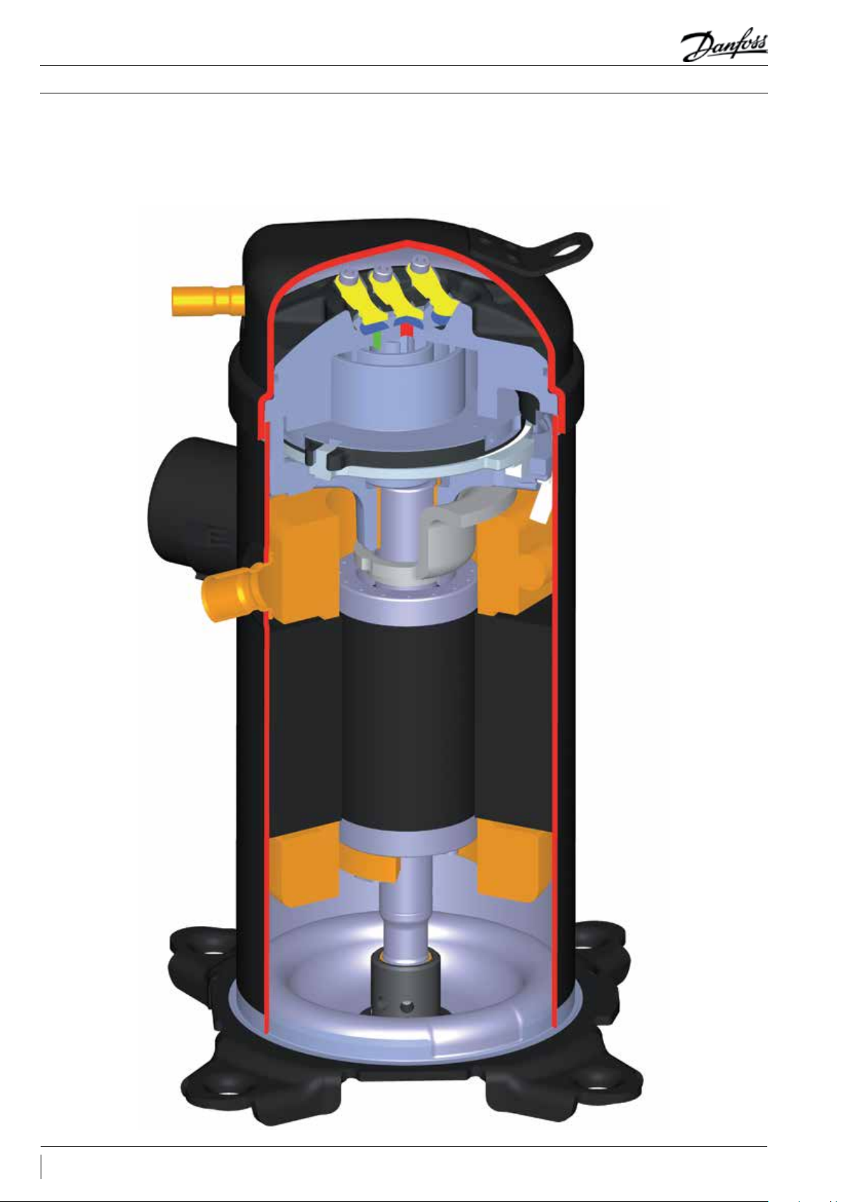
Scroll compressor
components
The motor stator is rigidly attached to the shell.
The rotor is shrink-t onto the eccentric shaft. The
shaft is supported by two bearings, one in the
crankcase and the second below the motor.
6 FRCC.PC.017.A2.02
Page 7
Application Guidelines
Scroll compression principle
The scroll compression
process
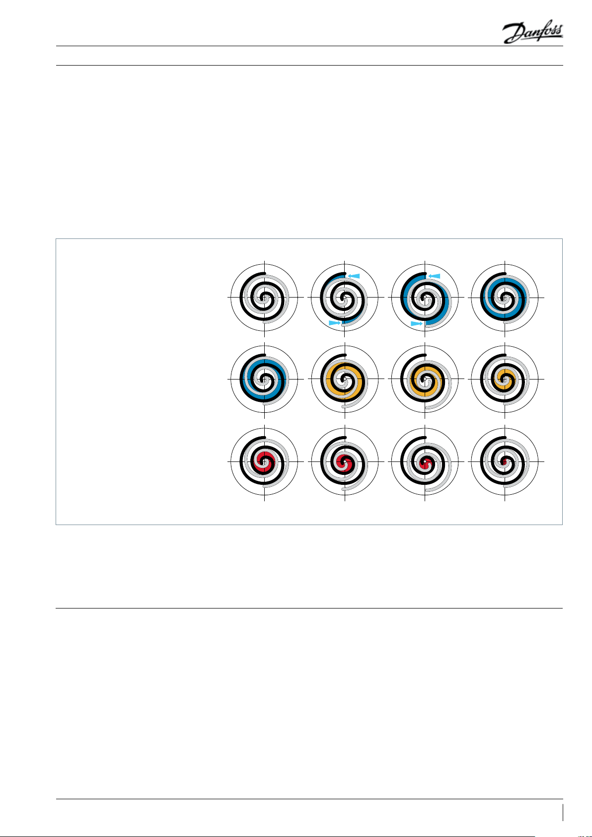
SUCTION
The entire scroll compression process is illustrated
below. The centre of the orbiting scroll traces a
circular path around the centre of the xed scroll.
This movement creates compression pockets
between the two scroll elements.
Low pressure suction gas is trapped within each
crescent-shaped pocket as it forms; continuous
motion of the orbiting scroll serves to seal
the pocket, which decreases in volume as the
pocket moves towards the centre of the scroll
set, with corresponding increase in gas pressure.
Maximum compression is achieved, as the pocket
reaches the discharge port at the centre.
Scroll compression is a continuous process: when
one pocket of gas is being compressed during
the second orbit, another gas quantity enters
a new pocket formed at the periphery, and
simultaneously, another is being discharged.
COMPRESSION
DISCHARGE
Performance
Danfoss Heat Pump scroll compressors are
manufactured using the most advanced
machining, assembly, and process control
techniques. In design of both the compressor
The Danfoss Heat Pump scroll compressor
referenced in this guide is a fully compliant
scroll and actually improves with run time in
and the factory, very high standards of reliability
and process control were rst priority. The result
is a highly ecient product with the highest
reliability obtainable, and a low sound level.
it's early commissioning. A seventy-two hour
run-in is recommended to meet performance
expectations.
7FRCC.PC.017.A2.02
Page 8
Application Guidelines
Nomenclature
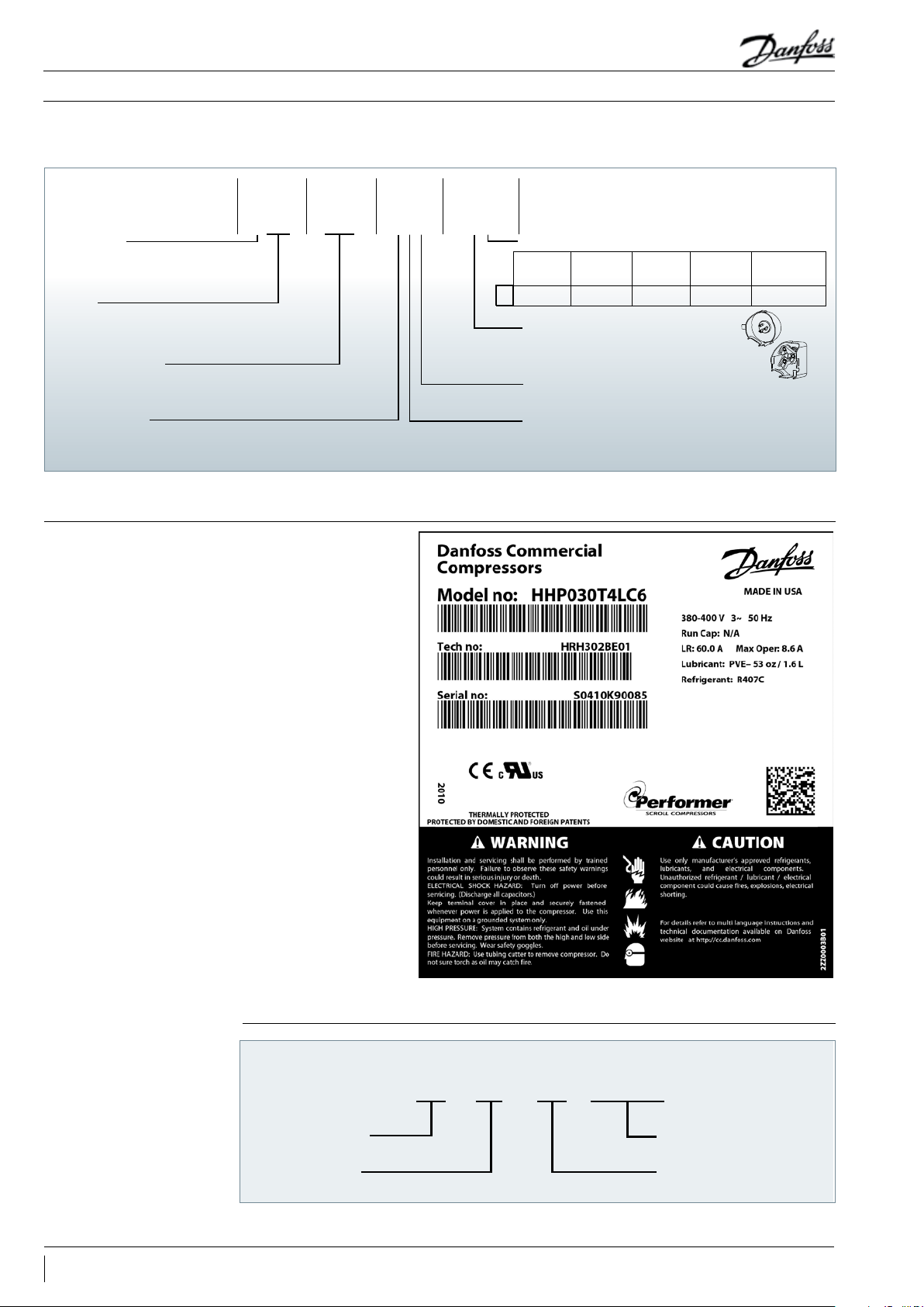
Compressor model designation
Type FeaturesMotorSize
Application:
H: high temperature
Family:
HP: heat pump R407C PVE
Nominal capacity:
Model variation
T motor design
Label
HHP P6T4L
030
Other features
Oil sight
6
Tubing and electrical connections
Motor protection
Motor voltage code
Oil equali-
glass
None
P: brazed connections, spade terminals
C: brazed connections, screw terminals
L: internal motor protection
4: 380-400V/3~/50 Hz
5: 220-240V/1~/50 Hz
sation
None None None None
Oil
drain
LP gauge
port
Gas equali-
sation port
Serial number
8 FRCC.PC.017.A2.02
Production week
Production year
S K 1234509
03
Incremental number
Manufacturing location
Page 9

Application Guidelines
50-Hz data
Technical specications
Model
Heating
capacity
Power input Max. A.
W W A COP W/ W (cm
Heating
eciency
Swept volume Displacement Oil charge Net weight
3
/rev)
m3/hr @2900
rpm
L kg
HHP015T4LP6 4800 154 0 5.1 3.13 34 5.9 1.06 31
HHP015T5LP6 4880 1660 14. 2 2.93 34 5.9 1.06 31
HHP019T4LP6 5780 1910 5.8 3.02 41 7.1 1.06 33
HHP019T5LP6 5830 2040 17.7 2.86 41 7.1 1.06 33
HHP021T4LP6 6 410 2030 5.8 3.16 46 8 1. 06 33
HHP021T5LP6 6630 2110 18. 2 3.15 46 8 1.06 33
HHP026T4LP6 8100 2520 7.1 3.22 57 10 1.06 33
HHP026T5LP6 8160 2680 22.7 3.04 57 10 1.0 6 33
HHP030T4LC6 9700 3070 8.6 3 .17 67 11.7 1.57 33
HHP030T5LC6 9790 3190 27.7 3.07 67 11. 7 1.57 42
HHP038T4LC6 12050 3730 10. 8 3.23 82 14.2 1.57 42
HHP038T5LC6 12140 3850 35.2 3 .16 82 14.2 1.57 42
HHP045T4LC6 13940 4300 12.6 3.25 99 17. 2 1.57 42
Evaporating temperature: -7° C Condensing temperature: 50°C Superheat: 10 K Subcooling: 5 K
Subject to modication without prior notication Conditions: 400V/3ph/50Hz (motor T4), 230V/1ph/50 Hz (motor T5)
For full data details and capacity tables refer to Online Datasheet Generator : www.danfoss.com/odsg
Performance table
Model
HHP015T4
HHP019T4
HHP021T4
HHP026T4
HHP030T4
HHP038T4
HHP045T4
To -25 -20 -15 -10 -5 0 5 10 15
Tc H Pe H Pe H Pe H Pe H Pe H Pe H Pe H Pe H Pe
40 2 550 1.1 3 070 1.1 3 720 1.2 4 510 1. 3 5 450 1.3 6 520 1.4 7 730 1.4 9 080 1.4 10 570 1.4
50 2 620 1.5 3 050 1. 5 3 620 1.5 4 320 1.5 5 15 0 1.6 6 120 1.6 7 220 1.7 8 460 1. 7 9 840 1.7
60 - - - - 3 860 2.2 4 410 2.1 5 090 2.1 5 890 2.1 6 830 2.1 7 900 2.1 9 10 0 2 .1
40 3 070 1.3 3 680 1. 4 4 450 1.5 5 400 1.5 6 520 1.6 7 810 1.7 9 270 1.7 10 900 1.7 12 690 1.7
50 3 180 1.7 3 680 1.7 4 340 1.8 5 180 1.9 6 180 1.9 7 340 2.0 8 670 2.1 10 160 2.2 11 83 0 2.2
60 - - - - 4 660 2.3 5 300 2.4 6 110 2.4 7 070 2.5 8 200 2.6 9 480 2.7 10 930 2.8
40 3 530 1.4 4 250 1. 5 5 090 1. 6 6 080 1.7 7 230 1.7 8 570 1.8 10 100 1.8 11 8 40 1.7 13 82 0 1.7
50 3 430 1.6 4 080 1.8 4 860 1.9 5 770 2.0 6 830 2.1 8 070 2.1 9 500 2.2 11 14 0 2.2 13 000 2.2
60 - - - - 4 710 2.2 5 530 2.3 6 510 2.5 7 650 2.6 8 970 2.7 10 490 2.8 12 24 0 2.8
40 4 540 1.7 5 410 1.9 6 440 2.0 7 650 2 .1 9 070 2 .1 10 74 0 2.2 12 6 90 2.2 14 950 2.1 17 550 2.0
50 4 590 2.0 5 350 2.1 6 260 2.3 7 330 2.4 8 610 2.6 10 120 2.6 11 90 0 2.7 13 9 70 2.7 16 370 2.7
60 - - - - 6 240 2.7 7 150 2.9 8 250 3.0 9 560 3.2 11 1 30 3.3 12 980 3.3 15 150 3.3
40 4 910 2.1 6 100 2.3 7 480 2.4 9 050 2.6 10 830 2.6 12 83 0 2.7 15 0 60 2.7 17 5 20 2.8 20 24 0 2.9
50 4 830 2.3 5 940 2.6 7 230 2.8 8 690 3.0 10 350 3.1 12 200 3. 2 14 270 3.4 16 560 3.5 19 090 3.6
60 - - - - 7 000 3.1 8 330 3.4 9 850 3.6 11 550 3.8 13 4 40 4.0 15 540 4.2 17 870 4.4
40 6 150 2.4 7 600 2.8 9 360 3.0 11 390 3.2 13 6 60 3.2 16 130 3.3 18 750 3. 3 21 510 3.4 24 360 3.6
50 5 730 2.2 7 120 2.8 8 800 3.3 10 740 3.6 12 890 3.8 15 220 4.0 17 7 00 4 .1 20 280 4.2 22 940 4.4
60 - - - - 8 090 3.2 9 930 3.8 11 9 70 4.2 14 17 0 4.5 16 5 00 4.7 18 920 5.0 21 4 00 5.2
40 7 110 3.0 8 80 0 3.1 10 830 3.3 13 18 0 3.5 15 8 00 3.7 18 66 0 3.8 21 700 3.9 24 890 3.8 28 18 0 3.7
50 6 630
60 - - - - 9 360 4.5 11 49 0 4.8 13 8 50 5.1 16 40 0 5.5 19 10 0 5.7 21 890 6.0 24 76 0 6.1
3.5 8 240 3.7 10 190 3.9 12 420 4.2 14 910 4.4 17 610 4.6 20 480 4.7 23 460 4.8 26 540 4.8
Legend: To: Evaporating temperature in °C H: Heating capacity in W Superheat = 5 K
Tc: Condensing temperature in °C Pe: Power input in kW Subcooling = 5 K
9FRCC.PC.017.A2.02
Page 10
Application Guidelines
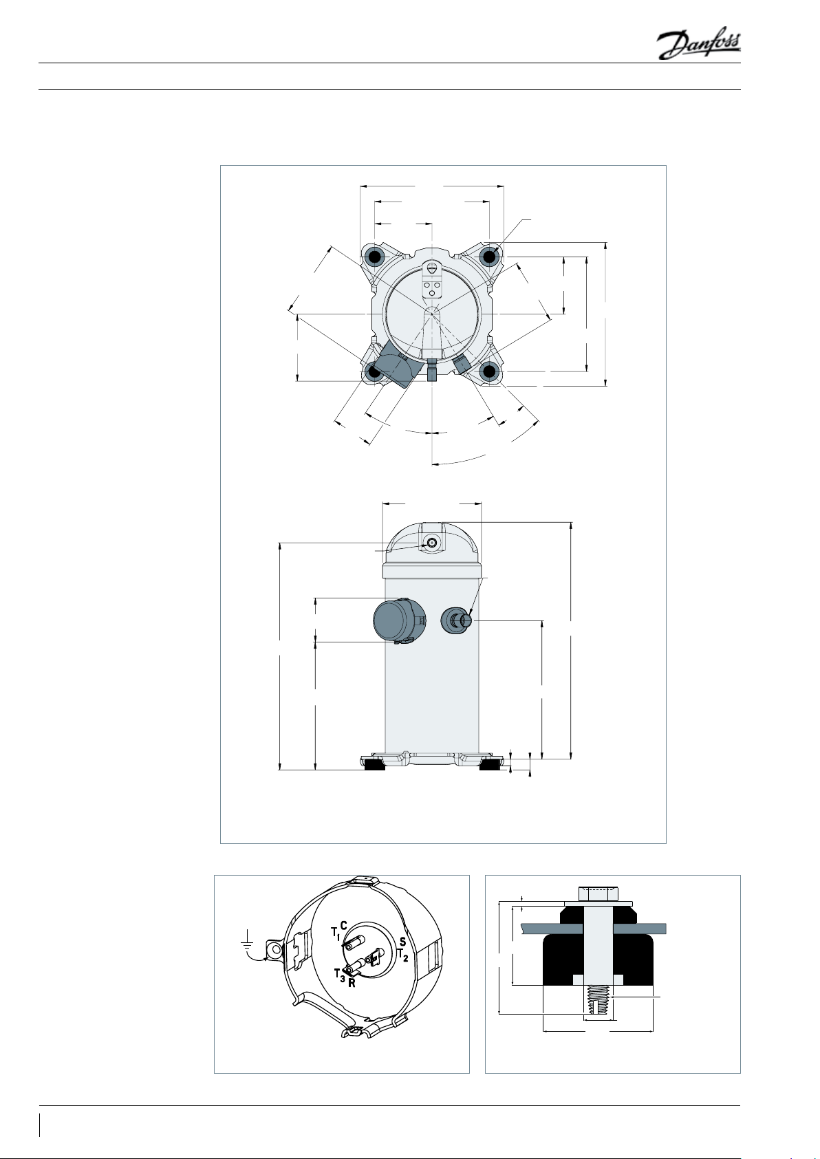
HHP015-019-021-026
Dimensions
238.8
190.25 - 190.75
95.25
4 x Ø 19.0 - 20.0
111.3
360.4
128.5
69.4 - 71.4
Discharge line
12.75-12.85
(1/2 inch)
72.1 - 75.1
34°
163.5 - 165.5
31°
109.7
14°
45°
Suction line
(1) 19.13-19.23
(3/4 inch)
95.25
238.8
190.25 - 190.50
394.4
194.9
HHP 015-019-021-026
All dimensions in mm
Quick connect spade terminals
P terminal box type
230.8
10.7
19
P6
Mounting grommetTerminal box
1.7
29.5
41
5/16” - 18 UNC
Ø11
Ø 41
Recommended torque for mounting bolts:
11 Nm (±1 Nm)
Refer to section "Spare parts and accessories" for overview of shipped mounting accessories
self tapping
10 FRCC.PC.017.A2.02
Page 11

239
Application Guidelines
HHP030-038-045
Dimensions
Discharge line
12.75-12.85
(1/2 inch)
402.7
133.6
121
78.5 - 80.5
92.0 - 94.0
190.25 - 190.75
95.25
34°
182.54 - 184.54
31°
4 x Ø 19.0 - 20.0
95.25
119.2
239
190.25 - 190.75
14°
45°
Suction line
22.30-22.48
(7/8 inch)
435.9
HHP030-038-045
All dimensions in mm
C
T₁
R
T₃
Ring connect screw terminals
C terminal box type
202.4
261
10.9
19
C6
Mounting grommetTerminal boxes
1.7
S
T₂
29.5
41
5/16” - 18 UNC
Ø11
self tapping
Ø 41
Recommended torque for mounting bolts:
11 Nm (±1 Nm)
Refer to section "Spare parts and accessories" for overview of shipped mounting accessories
11FRCC.PC.017.A2.02
Page 12
Application Guidelines
Electrical data, connections and wiring
Danfoss Heat Pump scroll compressors are available in 2 dierent motor voltages.Motor voltage
Motor voltage code 4 Motor voltage code 5
Nominal voltage 50 Hz 380-400V-3-50 Hz 220-240V-1-50 Hz
Voltage range 50 Hz 340 - 440 198 - 264
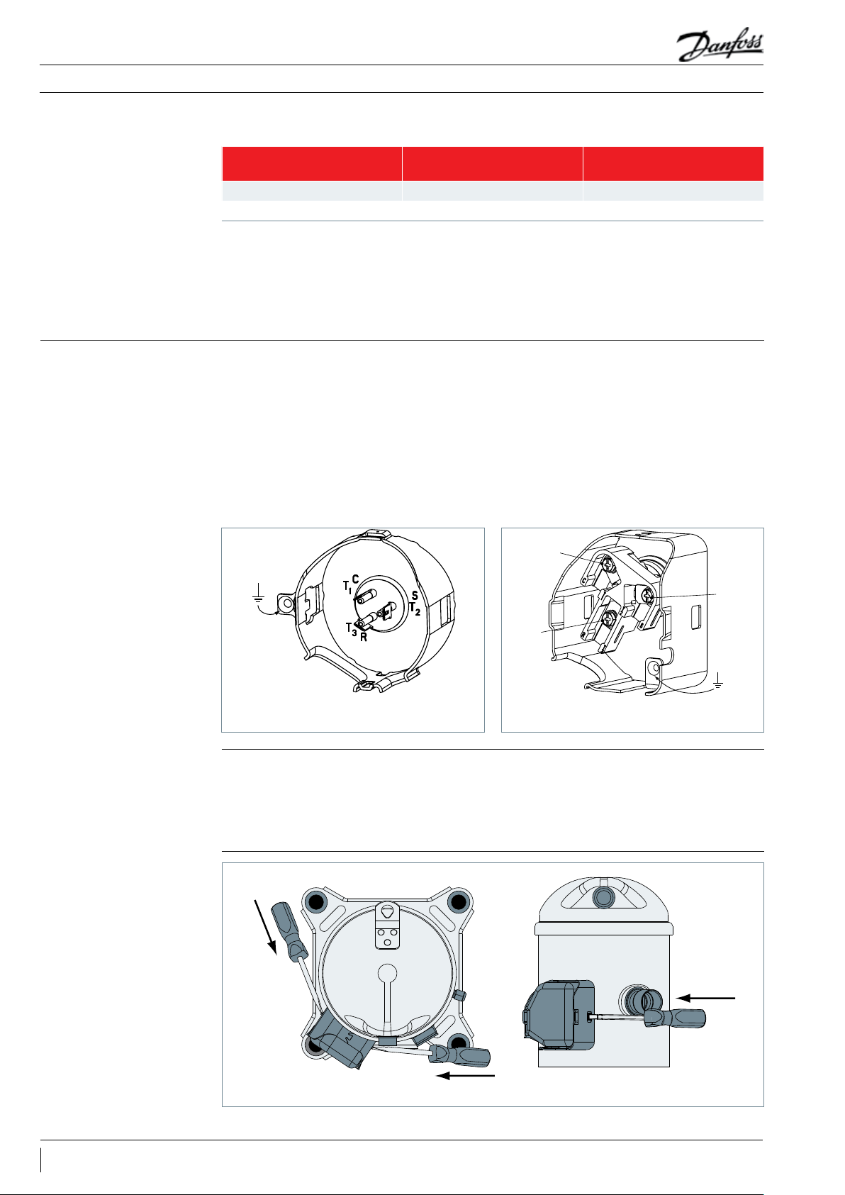
Wiring connections
Prior to energizing, verify that leads and terminal
connectors are in proper working condition.
Danfoss Heat Pump scroll compressors will only
compress gas while rotating counter-clockwise
(when viewed from the compressor top). Since
single-phase motors will start and run in only
one direction, reverse rotation is not a major
consideration. Three-phase motors, however,
will start and run in either direction, depending
on the phase angles of the supplied power. Care
must be taken during installation to ensure that
the compressor operates in the correct direction
Warning: For safety reasons, make voltage
measurements at the unit contactor, not at
compressor terminals. Always keep the terminal
cover in place when the compressor is energized.
(see “Phase sequence and reverse rotation
protection”).
The drawings below show electrical terminal
labelling and should be used as a reference
when wiring the compressor. For three phase
applications, the terminals are labelled T1, T2, and
T3. For single-phase applications the terminals
are labelled C (common), S (start), and R (run).
C
T₁
S
T₂
R
T₃
Terminal cover mounting
Terminal cover removal
Quick connect spade terminals
P terminal box type
The terminal cover and gasket should be installed
prior to operation of the compressor. The terminal
cover has two outside tabs, 180 degrees apart,
that engage the terminal fence. When installing
push
push
Ring connect screw terminals
C terminal box type
the cover, check that it is not pinching the lead
wires. Both the inside of the terminal cover and
the gasket have labels for the terminal pins: C
(common), R (run), and S (start).
push
12 FRCC.PC.017.A2.02
Page 13
Application Guidelines
Electrical data, connections and wiring
IP rating
LRA (Locked Rotor Amp)
MCC (Maximum
Continuous Current)
The compressor terminal box IP rating according to CEI 529 is IP22 for all models. IP ratings is only valid
when correctly sized cable glands of the IP rating is applied.
• First numeral, level of protection against contact and foreign objects
2 protection against object size over 12.5 mm (ngers of similar)
• Second numeral, level of protection against water
2 protection against dripping water when tilted up to 15°
LRA is the higher average current as measured on
a mechanically blocked compressor tested under
nominal voltage. LRA is printed on the nameplate.
The MCC is the current at which the internal
motor protection trips under maximum load and
low voltage conditions.
The LRA value can be used as a rough estimation
for the starting current. However in most cases,
the real starting current will be lower. Many
countries have dened limits for the starting
current in domestic use. A soft starter can be
applied to reduce starting current.
This MCC value is the maximum at which
the compressor can be operated in transient
conditions and out of the application envelope.
Above this value the overload will switch o to
protect the motor.
Max Oper. A (Maximum
Operating Amp)
The Max Oper. A is the current when the
compressor operates at maximum load conditions
and 10% below nominal voltage.
This value which is the max rated load current for
the compressor is new on the nameplate.
Winding resistance Winding resistance is the resistance between
indicated terminal pins at 25°C (resistance value
+/- 7%).
Winding resistance is generally low and it
requires adapted tools for precise measurement.
Use a digital ohm-meter, a ‘4 wires’ method and
measure under stabilised ambient temperature.
Winding resistance varies strongly with winding
temperature ; If the compressor is stabilised at a
dierent value than 25°C, th e measured resistance
must be corrected with following formula:
Electrical connections
The Danfoss Heat Pump scroll compressors are
designed to operate without any assistance if
Max Oper. A can be used to select cables and
contactors.
In normal operation, the compressor current
consumption is always less than the Max Oper. A
value.
a + t
R
= R
tamb
a + t
t
25°C
t
amb
R
25°C
R
amb
25°C
: reference temperature = 25°C
: temperature during measurement (°C)
: winding resistance at 25°C
: winding resistance at t
amb
25°C
amb
coecient a= 234.5
running within the dened nominal voltage. PSC
wiring is sucient (see below).
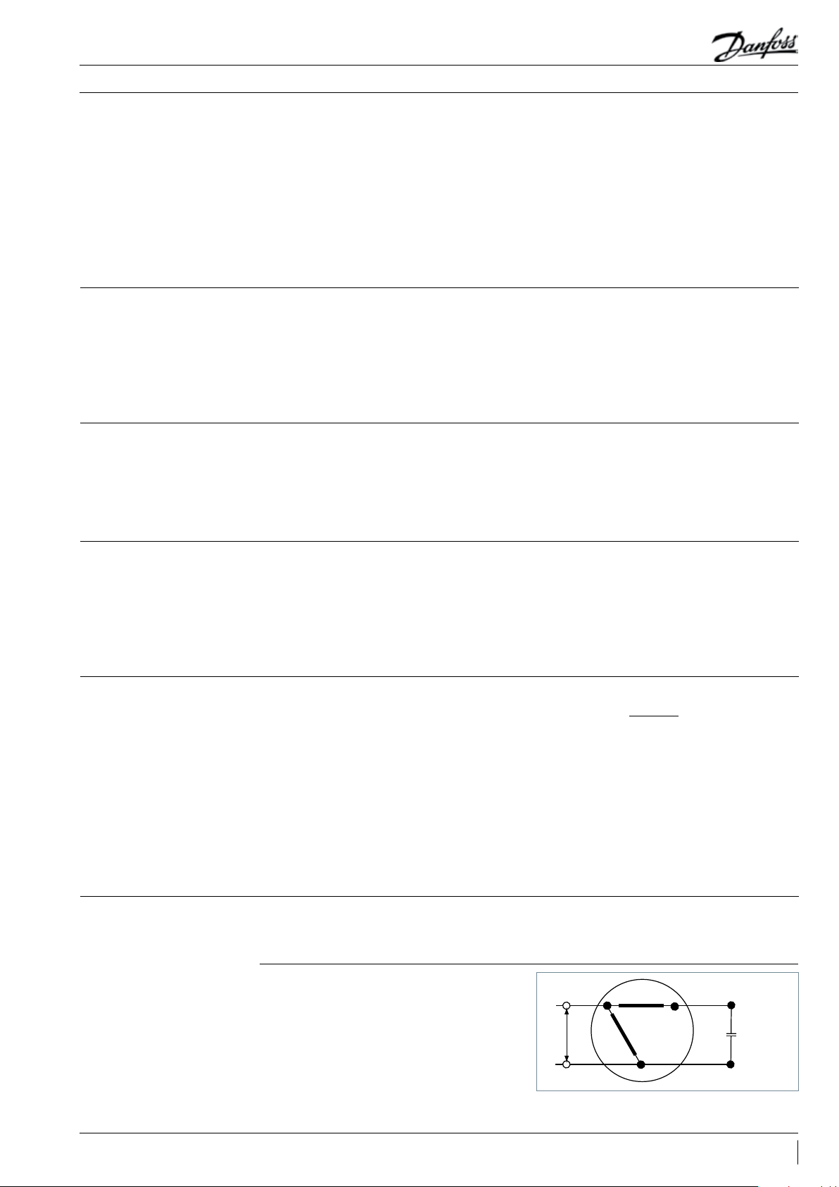
PSC wiring
The start winding (C-S) of the motor remains in
circuit through a permanent (run) capacitor.
This permanent (run) capacitor is connected
between the start winding (C-S) and the run
winding (C-R).
Line
C
S
Run
Capacitor
R
13FRCC.PC.017.A2.02
Page 14

Application Guidelines
Electrical data, connections and wiring
CSR wiring
If start assist is required, in case of operating
below the nominal voltage, a CSR starting device
is required.
During start-up, the start winding (C-S) is
energised through an electromagnetic potential
relay and a start capacitor.
A permanent (run) capacitor is wired between the
start winding (C-S) and the run winding (C-R).
Nominal capacitor value
HHP015T5LP6 40
HHP019T5LP6 60
HHP021T5LP6 60
HHP026T5LP6 70
HHP030T5LC6 50
HHP038T5LC6 55
PSC wiring
Run capacitor
Internal motor protection The Danfoss Heat Pump scroll compressors are
equipped with an internal line break protector
mounted on the motor windings. The protector
is an automatic reset device, containing a snap
action bimetal switch.
Internal protectors respond to over-current and
overheating. They are designed to interrupt
motor current under a variety of fault conditions,
such as failure to start, running overload, and fan
failure.
5
Potential
Relay
2
Run
Capacitor
1
Start
Capacitor
Line
C
S
R
If the internal overload protector trips out, it must
cool down to about 60°C to reset. Depending on
ambient temperature, this may take up to several
hours.
In single-phase compressors, internal protectors
guard against external miswiring, such as
reversing electrical connections to the Run (R) and
Start (S) terminals. In three-phase compressors
the internal protectors provide protection during
secondary single-phase conditions (loss of phase).
Phase sequence and
reverse rotation
protection
Voltage imbalance
The Danfoss Heat Pump scroll compressors will
only operate properly in a single direction. Use
a phase meter to establish the phase orders and
connect line phases L1, L2 and L3 to terminals
T1, T2 and T3, respectively. For three-phase
compressors, the motor will run equally well
in both directions. Reverse rotation results in
excessive noise; no pressure dierential between
suction and discharge; and suction line warming
rather than immediate cooling. A service
technician should be present at initial start-up to
verify that supply power is properly phased and
that compressor and auxiliaries are rotating in the
correct direction.
For three-phase applications the voltage
measured at the compressor terminals for each
Danfoss Heat Pump scroll compressors are
designed to operate for a maximum of 150 hours
in reverse, but as a reverse rotation situation can
go unnoticed for longer periods, phase monitors
are recommended.
At brief power interruptions, reverse rotation can
occur with single phase compressors. In this case
the internal protector will stop the compressor.
It will have to cool down and will restart safely
afterwards.
phase should be within ± 2% of the average for
all phases.
14 FRCC.PC.017.A2.02
Page 15

Application Guidelines
Approvals and certications
Approvals and certicates
Pressure equipment
directive 97/23/EC
Low voltage directive
73/23/EC, 93/68/EC
The Danfoss Heat Pump scroll compressors
comply with the following approvals and
Certicates are listed on the product datasheets:
http://www.danfoss.com/odsg
certicates.
CE 0062 or CE 0038
(European Directive)
UL
(Underwriters Laboratories)
Other approvals / certicates CB certicate available upon request
Products HHP015-019-021-026-030-038
Refrigerating uids Group 2
Category PED I
Evaluation module no scope
Products
Manufacturer's declaration of incorporation
ref. EC Machines Directives 98/392/CE
All models
All models
Contact Danfoss
Internal free volume
Products Internal free volume at LP side without oil (litre)
HHP015-019-021-026 2.93
HHP030-038-045 3.44
15FRCC.PC.017.A2.02
Page 16

Application Guidelines
Operating conditions
The Danfoss Heat Pump scroll compressors
application range is inuenced by several
parameters which need to be monitored for a
safe and reliable operation.
These parameter s and the main recommendations
for good prac tice and safety devices are explained
hereunder.
Refrigerant and lubricants
General information
Oil type - PVE Polyvinyl ether (PVE) is an innovative refrigeration
When choosing a refrigerant, dierent aspects
must be taken into consideration:
• Legislation (now and in the future)
• Safety
• Application envelope in relation to expected
running conditions
• Compressor capacity and eciency
• Compressor manufacturer recommendations &
guidelines
lubricant for HFC refrigerant systems. PVE is as
hygroscopic as existing polyolester lubricants
(POE), but PVE doesn’t chemically react with
water; no acids are formed and compressor
evacuation is easier.
• Refrigerant and lubricants
• Motor supply
• Compressor ambient temperature
• Application envelope (evaporating
temperature, condensing temperature, return
gas temperature)
Additional points could inuence the nal choice:
• Environmental considerations
• Standardisation of refrigerants and lubricants
• Refrigerant cost
• Refrigerant availability
The compressor technology applied in the
Danfoss Heat Pump scroll compressors in
combination with PVE lubricant provides the
best possible result in terms of reliability and
compressor lifetime.
The PVE lubricant is compatible with R22 which
makes the Danfoss Heat Pump scroll compressors
a very versatile multi- refrigerant solution.
Motor supply
Compressor ambient
temperature
High ambient temperature
Low ambient temperature
The Danfoss Heat Pump scroll compressors can
be operated at nominal voltages as indicated in
section "Electrical data, connections and wiring".
Under-voltage and over-voltage operation is
allowed within the indicated voltage ranges. In
The Danfoss Heat Pump scroll compressors
can be applied from -35°C to 50°C ambient
temperature. The compressors are designed
In case of enclosed tting and high ambient
temperature it’s recommend to check the
temperature of power wires and conformity to
their insulation specication.
Although the compressor itself can withstand low
ambient temperature, the system may require
specic design features to ensure safe and reliable
case of risk of under-voltage operation, special
attention must be paid to current draw and
start assist for single-phase compressors may be
required.
as 100 % suction gas cooled without need for
additional fan cooling. Ambient temperature has
very little eect on the compressor performance.
In case of safe tripping by the internal compressor
overload protection the compressor must cool
down to about 60°C before the overload will
reset. A high ambient temperature can strongly
delay this cool-down process.
operation. See section ‘Specic application
recommendations’.
16 FRCC.PC.017.A2.02
Page 17

Application Guidelines
Operating conditions
Application envelope
R407C
The operating envelope for Danfoss Heat
Pump scroll compressors are given in the gure
below, where the condensing and evaporating
temperatures represent the range for steady-s tate
operation. Under transient conditions, such as
start-up and defrost for heat pump applications,
the compressor may operate outside this
envelope for short periods.
The operating limits serve to dene the
envelope within which reliable operations of the
compressor are guaranteed:
70
60
50
40
Continuous operation ranges - R407C dew
SH = 5 K
SH = 10 K
• Maximum discharge gas ow temperature:
140 °C,
• A suction superheat below 5 K is not
recommended due to the risk of liquid ood
back,
• Maximum superheat of 30 K as long as maximum
discharge gas temperature is not exceeded,
• Minimum and maximum evaporating and
condensing temperatures as per the operating
envelopes.
Maximum discharge gas
temperature
Discharge gas temperature
protection (DGT)
30
Condensing temperature (°C)
20
10
-25 -20 -15 -10 -5 0 5 10 15 20
Evaporating temperature (°C)
The discharge temperature depends mainly on
the combination of evaporating temperature,
condensing temperature and suction gas
superheat. Discharge gas temperature should
be controlled with an isolated thermocouple or
DGT protection is required if the high and low
pressure switch settings do not protect the
compressor against operations beyond its
specic application envelope. Please refer to
the examples below, which illustrate where DGT
thermostat attached to the discharge line 15 cm
from the compressor shell. Maximum discharge
gas temperature must not exceed 140°C when
the compressor is running within the approved
operating envelope.
The compressor must not be allowed to cycle
on the discharge gas thermostat. Continuous
operations beyond the compressor’s operating
range will cause serious damage to the
compressor!
protection is required (n°1) and where it is not
(n°2).
A DGT accessory is available from Danfoss: refer to
section "Spare parts and accessories".
17FRCC.PC.017.A2.02
Page 18

Application Guidelines
Operating conditions
Example 1 (R407C)
LP switch setting: LP1= 1.1 bar (g) (-20°C)
HP switch setting: HP1= 24.3 bar (g) (60°C)
The LP and HP switches don't protect
suciently from operation outside the
envelope. A DGT protection is required
to avoid operation in the hatched area.
Example 2 (R407C)
LP switch setting: LP2 = 2.3 bar (g) (-9°C)
HP switch setting: HP2 = 18.8 bar (g) (50°C)
The LP and HP switches protect from
operation outside the envelope. No
DGT protection required.
70
60
50
40
30
Condensing temperature °C
20
10
-30 -25 -20 -15 -10 -5 0 5 10 15 20
Continuous operation ranges - R407C dew
LP1
LP2
Evaporating temperature °C
The discharge gas thermostat accessory kit
includes all components required for installation,
as shown below. The thermostat must be
attached to the discharge line within 150 mm
from the compressor discharge port.
Example 1
Example 2
Discharge line
Bracket
HP1
HP2
Thermostat
Insulation
High and low pressure
protection
High pressure
Low pressure
R407C
Working pressure range high side bar (g)
Working pressure range low side bar (g)
Maximum high pressure safety switch setting bar (g) 30
Minimum low pressure safety switch setting
bar (g)
Maximum test pressure bar (g) 30
LP safety switch shall never be bypassed. Depends on the models, check on the nameplate
A high-pressure (HP) safety switch is
recommended to shut down the compressor
should the discharge pressure exceed the values
shown in the table below. The high-pressure
switch can be set to lower values depending on
the application and ambient conditions. The HP
switch must either be placed in a lockout circuit or
consist of a manual reset device to prevent cycling
around the high-pressure limit. If a discharge
to the service valve gauge port, which must not
be isolated.
Note: because power consumption of scroll
compressors is almost directly proportional to
discharge pressure, the high-pressure control can
be used to indirectly limit the maximum current
draw. A high-pressure control used in this manner
however can never replace an external overload
protector.
7.8 - 27. 4
0.7 - 6.6
0.5
valve is used, the HP switch must be connected
A low pressure (LP) safety switch is recommended.
Deep vacuum operations of a scroll compressor
can cause internal electrical arcing and scroll
instability. Danfoss Heat Pump scroll compressors
exhibit high volumetric eciency and may draw
very low vacuum levels, which could induce such
a problem. The minimum low-pressure safety
switch (loss of charge safety switch) setting is
given in the above table. For systems without
pump-down, the LP safety switch must either be
a manual lockout device or an automatic switch
wired into an electrical lockout circuit. The LP
switch tolerance must not allow for vacuum
operations of the compressor. LP switch settings
for pump-down cycles with automatic reset are
also listed in the table above.
On/o cycling (cycle rate
limit)
18 FRCC.PC.017.A2.02
Danfoss recommends a restart delay timer to limit
compressor cycling. The timer prevents reverse
compressor rotation, which may occur during
brief power interruptions.
The system must be designed in a way that
guarantees a minimum compressor running time
of 2 minutes so as to provide for sucient motor
cooling after start-up along with proper oil return.
Note that the oil return may vary since it depends
upon system design.
There must be no more than 12 starts per hour, a
number higher than 12 reduces the service life of
the motor-compressor unit. A three-minute (180sec) time out is recommended.
Page 19

Application Guidelines
System design recommendations
General Successful application of scroll compressors is
dependent on careful selection of the compressor
for the application. If the compressor is not correc t
Essential piping design
considerations
Proper piping practices should be employed to
ensure adequate oil return, even under minimum
load conditions with special consideration given
to the size and slope of the tubing coming
from the evaporator. Tubing returns from the
evaporator should be designed so as not to trap
oil and to prevent oil and refrigerant migration
back to the compressor during o-cycles.
If the evaporator lies above the compressor, the
suction line must have a loop at the evaporator
outlet to prevent refrigerant from draining into
the compressor during o-cycles.
If the evaporator were situated below the
compressor, the suction riser must be trapped so
as to prevent liquid refrigerant from collecting at
the thermal bulb location (see g. 1).
When the condenser is mounted at a higher
position than the compressor, a suitably sized
«U»-shaped trap close to the compressor is
necessary to prevent oil leaving the compressor
for the system, it will operate beyond the limits
given in this manual. Poor performance, reduced
reliability, or both may result.
from draining back to the discharge side of the
compressor during o cycle. The upper loop also
helps avoid condensed liquid refrigerant from
draining back to the compressor when stopped
(see g. 2). The maximum elevation dierence
between the indoor and outdoor section cannot
exceed 8 m. System manufacturers should specify
precautions for any applications that exceed
these limits to ensure compressor reliability.
Piping should be designed with adequate three-
dimensional exibility. It should not be in contact
with the surrounding structure, unless a proper
tubing mount has been installed. This protection
proves necessary to avoid excess vibration, which
can ultimately result in connection or tube failure
due to fatigue or wear from abrasion. Aside from
tubing and connection damage, excess vibration
may be transmitted to the surrounding structure
and generate an unacceptable noise level within
that structure as well (for more information on
noise and vibration, see the section on: "Sound
and vibration management").
g.1
max. 4 m
max. 4 m
0.5 % slope,
4 m/s or more
U-trap, as short as possible
8 to 12 m/s
0.5 % slope,
4 m/s or more
U-trap, as short as possible
U-trap
Evaporator
To condenser
g. 2
Upper loop
Condenser
HP
U-trap
LP
3D exibility
19FRCC.PC.017.A2.02
Page 20

Application Guidelines
System design recommendations
Refrigerant charge limit
Danfoss Heat Pump scroll compressors can
tolerate liquid refrigerant up to a certain extend
without major problems. However, excessive
liquid refrigerant in the compressor is always
unfavourable for service life. Besides, the
installation cooling capacity may be reduced
because of the evaporation taking place in the
compressor and/or the suction line instead of the
evaporator. System design must be such that the
amount of liquid refrigerant in the compressor
is limited. In this respect, follow the guidelines
given in the section: “Essential piping design
recommendations” in priority.
Depending on test results, crankcase heaters, Liquid Line Solenoid Valve or suction accumulator must
be applied see below.
BELOW charge limit ABOVE charge limit
Packaged units No test or additional safeties required
System with remote heat exchanger O cycle migration test
Recommended Required No test or additional safeties required
REQREC
REC
Use the tables below to quickly evaluate the
required compressor protection in relation
with the system charge and the application.
More detailed information can be found in the
paragraphs hereafter. Please contact Danfoss for
any deviation from these guidelines.
Notes: for reversible heat pump systems and
other specic applications, please refer to section
"Specic application recommendations".
Compressor models Refrigerant charge limit (kg)
HHP015-019-021-026 3.6
HHP030-038-045 5.4
O cycle migration test
REQ
Liquid ood back test
REQ
O cycle migration test
REQ
Liquid ood back test
REQ
Note: for special conditions such as low ambient temperature, low load operation or brazed plate heat exchangers please refer to corresponding sections
Reversible heat pump
systems
Transients are likely to occur in reversible heat
pump systems, i.e. a changeover cycle from
cooling to heating, defrost or low-load short
accumulator needs to be installed. A crankcase
heater and discharge gas thermostat are required
for reversible heat pump applications.
cycles. These transient modes of operation may
lead to liquid refrigerant carryover (or ood back)
or excessively wet refriger ant return conditions. As
such, reversible cycle applications require specic
precautions for ensuring a long compressor
life and satisfactory operating characteristics.
These considerations cover the most important
issues in the realm of common applications.
Each application design however should be
thoroughly tested to ensure acceptable operating
characteristics.
Regardless of the refrigerant charge in the
system, specic tests for repetitive ood back
are required to conrm whether or not a suction
Split unit heating mode Repeat the test, but with the system in heating
mode and the outdoor temperature at -18°C
Requirement graph on the next page, a suction
accumulator is required.
dry bulb. If the sump superheat is not in the
“ACCEPTABLE ZONE” shown in the Flood back
20 FRCC.PC.017.A2.02
Page 21

Application Guidelines
System design recommendations
Heat pumps
INDOOR COIL
Expansion device
OUTDOOR COIL
Expansion device
SYSTEM CHARGE
TEST REQUIRED
ACCEPTABLE SUMP
SUPERHEAT
TEMPERATURE
ACCUMULATOR
REQUIRED
INDOOR COIL
Expansion device
OUTDOOR COIL
Expansion device
NON-
BLEED
NON-
BLEED
<3.6 kg (1)
<5.4 kg (2)
NO
NO YES
NO
BLEED BLEED
NON-
BLEED
YES NO YES
YES
NON-
BLEED
BLEED
>3.6 kg (1)
>5.4 kg (2)
BLEED
(1) HHP015-019-021-026
(2) HHP030-038-045
SYSTEM CHARGE
TEST REQUIRED
ACCEPTABLE SUMP
SUPERHEAT
TEMPERATURE
ACCUMULATOR
REQUIRED
18
16
14
12
10
8
6
Sump Superheat, K
4
<3.6 kg (1)
<5.4 kg (2)
`
YES
NO YES
YES NO YES
>3.6 kg (1)
>5.4 kg (2)
Floodback Requirement
Acceptable
<3.6 kg (1)
<5.4 kg (2)
YES
NO YES
YES NO YES
Unacceptable
>3.6 kg (1)
>5.4 kg (2)
2
0
-25 -20 -15 -10 -5 0 5 10 15
Saturated Suction Temp. °C
21FRCC.PC.017.A2.02
Page 22

Application Guidelines
System design recommendations
Crankcase heater
Minimum sump
superheat
Crankcase heaters provide extra compressor
protection, and should be considered for all
applications. For initial installation of precharged
The minimum sump temperature is in the
range from 6K to 17K above saturated suction
Loss of charge protection Danfoss Heat Pump scroll compressors do not
include a thermal valve protection; therefore,
all applications should consider loss of charge
protection :
• A low pressure switch in the low pressure side of
the system is required.
Oil level checking and
top-up
High pressure ratio
In installations with good oil return and line
runs up to 15 m, no additional oil is required. If
installation lines exceed 15 m, additional oil may
be needed. 1 or 2% of the total system refrigerant
charge (in weight) can be used to roughly dene
the required oil top-up quantity.
Danfoss Heat Pump scroll compressors are
machines with xed volume ratio, and operate
more eciently near the design pressure ratio. In
the extreme, do not exceed a 11:1 pressure ratio
(absolute discharge pressure to absolute suction
systems and for any ex tended power interruptions ,
the crankcase heater should be energized for 24
hours prior to compressor startup.
temperature. Refer to the ood back test criteria
section "System design recommendations".
• A discharge line thermostat set no higher than
140°C is recommended. The thermostat must
be a manual lockout type device (or electrical
lockout circuit) and be located within 150 mm
of the compressor discharge connection. The
discharge line thermostat must be insulated to
insure proper sensing and operation.
Always use oil from new cans.
Top-up the oil while the compressor is idle. Use
any accessible connector on the compressor
suction line and a suitable pump.
pressure) for extended periods. The Danfoss Heat
Pump scroll compressor is equipped with an
internal pressure relief valve for p rotection against
blocked condenser and fan failure conditions.
Preventing liquid ood
back
Testing for excessive
liquid ood back
Danfoss recommends the use of a thermostatic
expansion valve for all air conditioning and heat
pump applications. A TXV has two key benets:
it provides modulating control of the system
under varying load conditions, and it protects
the compressors from ood back during adverse
running conditions.
When the use of xed orice devices is specied
in the system design, and when a TXV is applied
at the limit of its control range, the following tests
should be conducted to determine if a suction
Water utilising systems Apart from residual moisture in the system
after commissioning, water could also enter the
refrigeration circuit during operation. Water in the
system shall always be avoided. Not only because
it can shortly lead to electrical failure, sludge in
sump and corrosion but in particular because it
can cause serious safety risks.
Common causes for water leaks are corrosion and
freezing.
Corrosion: Materials in the system shall be
compliant with water and protected against
corrosion.
Excessive liquid refrigerant ood back during
steady state operation is a major system design
consideration for all types of compressors. Oil
dilution that occurs with excessive ood back
can have a signicant adverse eect on bearing
reliability. Suction accumulators may be required
in some applications to prevent ood back.
accumulator is needed. Refer to the owcharts
section "System design recommendations" to
determine when to apply the excessive liquid
ood back test.
Freezing: When water freezes into ice its volume
expands which can damage heat exchanger
walls and cause leaks. During o periods water
inside heat exchangers could start freezing when
ambient temperature is lower than 0°C. During on
periods ice banking could occur when the circuit
is running continuously at too low load. Both
situations should be avoided by connecting a
pressure and thermostat switch in the safety line.
22 FRCC.PC.017.A2.02
Page 23

Application Guidelines
Sound and vibration management
Running sound level
Sound generation in a
refrigeration system / air
conditioning system
Danfoss Heat Pump scroll compressors are
designed with optimised discharge ports and
Code 4 Code 5
Model
HHP015
HHP019
HHP021
HHP026
HHP030
HHP038
HHP045
Sound power (dBA)
Without jacket
70 62 70 62
70 62 70 62
71 63 71 63
71 63 71 63
72 64 72 64
72 64 72 64
73 65 - -
Sound power (dBA)
wrap geometry to reduce the sound level
when a compressor is running.
With jacket
Typical sound and vibration in refrigeration and
air conditioning systems encountered by design
and service engineers may be broken down into
the following three source categories.
Sound radiation: This generally takes an
airborne path.
Sound power (dBA)
Without jacket
Sound power (dBA)
With jacket
Mechanical vibrations: These generally extend
along the parts of the unit and structure.
Gas pulsation: This tends to travel through the
cooling medium, i.e. the refrigerant.
The following sections will focus on the causes
and methods of mitigation for each of the above
sources.
Compressor sound
radiation
For sound radiating from the compressor, the
emission path is airborne and the sound waves
are travelling directly from the machine in all
directions.
The Danfoss Heat Pump scroll compressor is
designed to be quiet and the frequency of the
sound generated is pushed into the higher
ranges, which not only are easier to reduce but
also do not generate the penetrating power of
lower-frequency sound.
Mechanical vibrations V ibration isolation constitutes the primar y method
for controlling structural vibration. Danfoss Heat
Pump scroll compressors are designed to produce
minimal vibration during operations. The use of
rubber isolators on the compressor base plate or
on the frame of a manifolded unit is very eective
in reducing vibration being transmitted from
the compressor(s) to the unit. Rubber grommets
are supplied with all Danfoss compressors.
Once the supplied rubber grommets have been
properly mounted, vibration transmitted from
the compressor base plate to the unit are held
to a strict minimum. In addition, it is extremely
Use of sound-insulation materials on the inside of
unit panels is an eective means of substantially
reducing the sound being transmitted to the
outside. Ensure that no components capable
of transmitting sound/vibration within the unit
come into direct contact with any non-insulated
parts on the walls of the unit.
Because of the Danfoss’s unique design of a fullsuction gas & oil cooled motor, compressor body
insulation across its entire operating range is
possible.
important that the f rame supporting the mounted
compressor be of sucient mass and stiness to
help dampen any residual vibration potentially
transmitted to the frame. The tubing should be
designed so as to both reduce the transmission
of vibrations to other structures and withstand
vibration without incurring any damage. Tubing
should also be designed for three-dimensional
exibility. For more information on piping design,
please see the section entitled "Essential piping
design considerations".
Gas pulsation The Danfoss Heat Pump scroll compressors
have been designed and tested to ensure that
gas pulsation has been optimised for the most
commonly encountered pressure ratio. On heat
pump installations and other installations where
the pressure ratio lies beyond the typical range,
testing should be conducted under all expected
conditions and operating congurations to
ensure that minimum gas pulsation is present. If
an unacceptable level is identied, a discharge
muer with the appropr iate resonant volume and
mass should be installed. This information can be
obtained from the component manufacturer.
23FRCC.PC.017.A2.02
Page 24

Application Guidelines
Installation
Each Danfoss Heat Pump scroll compressor is shipped with printed Instructions for installation.
System cleanliness The refrigerant compression system, regardless
of the type of compressor used, will only provide
high eciency and good reliability, along with a
long operating life, if the system contains solely
the refrigerant and oil it was designed for. Any
other substances within the system will not
improve performance and, in most cases, will be
highly detrimental to system operations.
The presence of non-condensable substances
and system contaminants, such as metal
shavings, solder and ux, have a negative
impact on compressor service life. Many of these
contaminants are small enough to pass through a
mesh screen and can cause considerable damage
within a bearing assembly. The use of highly
hygroscopic POE and PVE oils in R407C and R410A
compressors requires that the oil be exposed to
the atmosphere just as little as possible.
Compressor handling and
storage
Compressors are provided with a lifting lug. This
lug should always be used to lift the compressor.
Once the compressor is installed, the lifting
lug should never be used to lift the complete
installation. The compressor must be handled
System contamination is one of main factors
aecting equipment reliability and compressor
service life. It is important therefore to take
system cleanliness into account when assembling
a refrigeration system.
During the manufacturing process, circuit
contamination may be caused by:
• Brazing and welding oxides,
• Filings and particles from the removal of burrs
in pipe-work,
• Brazing ux,
• Moisture and air.
Consequently, when building equipment and
assemblies, the following precautions must be
taken: never drill holes into the pipe-work after
installation.
with caution in the vertical position, with a
maximum inclination of 15° from vertical. Store
the compressor between -35°C and 50°C, not
exposed to rain or corrosive atmosphere.
Compressor mounting Maximum inclination from the vertical plane,
while operating must not exceed 7 degrees.
All compressors are delivered with 4 rubber
Compressor holding
charge
Each compressor is shipped with a nominal dry
nitrogen holding charge between 0.4 bar and
0.7 bar, and is sealed with elastomer plugs. The
plugs should be removed with care to avoid
oil loss when the holding charge is released.
Remove the suction plug rst and the discharge
Tube brazing procedure Do not bend the compressor discharge or suction
lines or force system piping into the compressor
connections, because this will increase stresses
Brazing material For copper suction and discharge ttings, use
copper-phosphorus brazing material. Sil-Fos® and
other silver brazing materials are also acceptable.
grommets and metal sleeves. Compressors must
always be mounted with these grommets.
plug afterwards. The plugs shall be removed only
just before connecting the compressor to the
installation in order to avoid moisture entering
the compressor. When the plugs are removed, it
is essential to keep the compressor in an upright
position to avoid oil spillage.
that are a potential cause of failure. Re commended
brazing procedures and material, are described
on following page.
If ux is required for the brazing operation, use
coated rod or ux core wire. To avoid system
contamination, do not brush ux on.
24 FRCC.PC.017.A2.02
Page 25

Heat shield
C B A
Application Guidelines
Compressor connection When brazing the compressor ttings, do not
Installation
overheat the compressor shell, which could
severely damage certain internal components
due to excessive heating. Use of a heat shield
and/or a heat-absorbent compound is highly
recommended. For brazing the suction and
discharge connections, the following procedure
is advised:
•
Make sure that no electrical wiring is connected
to the compressor.
•
Protect the terminal box and compressor
painted surfaces from torch heat damage (see
diagram).
•
Use only clean refrigeration-grade copper
tubing and clean all connections.
•
Purge nitrogen or CO2 through the compressor
in order to prevent against oxidation and
ammable conditions. The compressor should
not be exposed to the open air for extended
periods.
•
Use of a double-tipped torch is recommended.
•
Apply heat evenly to Area A until the brazing
temperature is reached. Move the torch to Area
B
and apply heat evenly until the brazing
temperature has been reached there as well, and
then begin adding the brazing material. Move
the torch evenly around the joint, in applying
only enough brazing material to ow the full
circumference of the joint.
•
Move the torch to area C only long enough to
draw the brazing material into the joint, but not
into the compressor.
•
Remove all remaining ux once the joint has
been soldered with a wire brush or a wet cloth.
Remaining ux would cause corrosion of the
tubing.
Ensure that no ux is allowed to enter into the
tubing or compressor. Flux is acidic and can cause
substantial damage to the internal parts of the
system and compressor.
The PVE oil used in Danfoss Heat Pump scroll
compressors is highly hygroscopic and will
rapidly absorb moisture from the air. The
compressor must therefore not be left open to
the atmosphere for a long period of time. The
compressor tting plugs shall be removed just
before brazing the compressor.
Before eventual unbrazing the compressor
or any system component, the refrigerant
charge must be removed from both the high
and low pressure sides. Failure to do so may
result in serious personal injury. Pressure
gauges must be used to ensure all pressures
are at atmospheric level.
For more detailed information on the appropriate
materials required for brazing or soldering, please
contact the product manufacturer or distributor.
For specic applications not covered herein,
please contact Danfoss for further information.
Vacuum evacuation and
moisture removal
Moisture obstruc ts the proper functioning of b oth
the compressor and the refrigeration system.
Air and moisture reduce service life and increase
condensing pressure, which causes abnormally
high discharge temperatures that are then
capable of degra ding the lubricating properties of
the oil. The risk of acid formation is also increased
by air and moisture, and this condition can also
lead to copper plating. All these phenomena may
cause both mechanical and electrical compressor
failures. The typical method for avoiding such
problems is a vacuum pump-down executed
with a vacuum pump, thus creating a minimum
vacuum of 500 microns (0.67 mbar). Please refer
to Bulletin "Vacuum pump down and dehydration
procedure".
Be sure to follow all government regulations
regarding refrigerant reclamation and storage.
25FRCC.PC.017.A2.02
Page 26

Application Guidelines
Installation
Liquid line lter driers A properly sized lter drier is required for all
Danfoss scroll applications. Danfoss recommends
DML (100% molecular seives) driers for HFC
refrigerants R407C with PVE oil. For servicing
of existing installations where acid formation is
present the Danfoss DCL solid core lter driers
Refrigerant charging
Insulation resistance and
dielectric strength
It is recommended that system charging be
done using the weighed charge method, adding
refrigerant to the high side of the system.
Charging the high and low sides of a system
Insulation resistance must be greater than 1
megohm when measured with a 500 volt direct
current megohm tester.
Each compressor motor is tested at the factory
with a high potential voltage (hi-pot) that
exceeds the UL requirement both in potential and
in duration. Leakage current is less than 0.5 mA.
Danfoss Heat Pump scroll compressors are
congured with the pump assembly at the top
of the shell, and the motor below. As a result, the
motor can be partially immersed in refrigerant
containing activated alumina are recommended.
The drier is to be oversized rather than under
sized. When selecting a drier, always take into
account its capacity (water content capacity),
the system refrigeration capacity and the system
refrigerant charge.
with gas simultaneously at a controlled rate is
also an acceptable method. Do not exceed the
recommended unit charge, and never charge
liquid to the low side.
and oil. The presence of refrigerant around the
motor windings will result in lower resistance
values to ground and higher leakage current
readings. Such readings do not indicate a faulty
compressor, and should not be cause for concern.
In testing insulation resistance, Danfoss
recommends that the system be rst operated
briey to distribute refrigerant throughout the
system. Following this brief operation, retest the
compressor for insulation resistance or current
leakage.
Compressor replacement
after motor burn out
If there has been a motor burnout follow the
evacuation procedure described on previous
page. Remove and replace the liquid line lter
drier and install a Danfoss type DAS burnout drier
of appropriate capacity.
Refer to the DAS drier instructions and technical
information on correct use and monitoring of the
burnout drier and the liquid line and suction line
lter driers.
26 FRCC.PC.017.A2.02
Page 27

Application Guidelines
Packaging
Ordering information and packaging
Single pack
Industrial pack
Compressors are packed individually in a
cardboard box. They can be ordered in any
quantity. Minimum ordering quantity = 1. As far
as possible, Danfoss will ship the boxes on full
pallets of 6 compressors according below table.
• Each box also contains following accessories:
• 4 grommets
• 4 assemblies of self tapping US thread bolts,
washers and sleeves
• 4 additional sleeves
• 1 screw for earth connection
• start capacitor for single phase (individual pack)
Compressors are not packed individually but are
shipped all together on one pallet. They can be
ordered in quantities of full pallets only, multiples
of 12 .
Each industrial pack pallet contains following
accessories:
• 4 grommets per compressor
• 4 sleeves per compressor
Packaging details
HHP015-019-021-026 198 407
HHP030-038-045 249 504
Model Weight for single pack (kg) Weight for Industrial pack (kg)
Ordering information and
packaging
Model Model Variation Connections Features
HHP015 T P 6 121U90 02 121U9004 121U9001 121U90 03
HHP019 T P 6 121U9006 121U 9008 121U9005 121U9007
HHP021 T P 6 121U9010 121U9012 121U9 009 121U9 011
HHP026 T P 6 121U9014 121U9016 121U 9013 121U9015
HHP030 T C 6 121U9 018 121U9020 121U9 017 121U9 019
HHP038 T C 6 121U 9022 121U9024 121U9 021 121U90 23
HHP045 T C 6 121U9 026 - 121U9 025 -
Single pack Industrial pack
4 5 4 5
27FRCC.PC.017.A2.02
Page 28
Application Guidelines
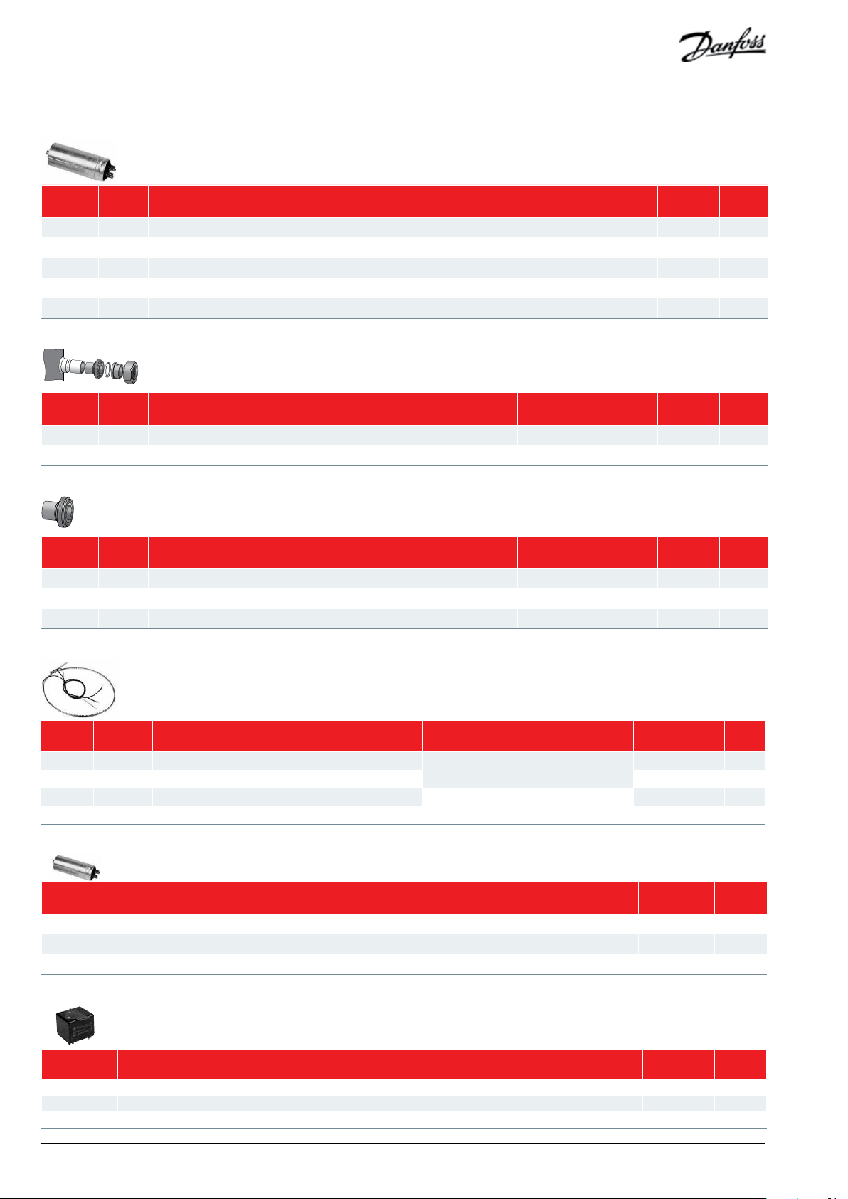
Run capacitors for PSC wiring
Spare parts & accessories
Typ e Code n° Description Application Packaging
40 µF 8173231 Run capacitor (µF) HHP015 Multipack 10
60 µF 120Z 005 0 Run capacitor (µF) HHP019, HHP021 Multipack 10
70 µF 120 Z0051 Run capacitor (µF) HHP026 Multipack 10
50 µF 8173 233 Run capacitor (µF) HHP030 Multipack 10
55 µF 817 3234 Run capacitor (µF) HHP038 Multipack 10
Rotolock adaptor set
Typ e Code n° Description Application Packaging
120Z0126 Rotolock adaptor set (1-1/4" ~ 3/4") , (1" ~ 1/2") HHP015-019-021-026 Multipack 6
120Z0127 Rotolock adaptor set (1-1/4" ~ 7/8") , (1" ~ 1/2") HHP030-038-045 Multipack 6
Rotolock adaptor
Typ e Code n° Description
120Z0366 Rotolock adaptor (1-1/4" ~ 3/4") HHP015-019-021-026 suction Multipack 10
120Z0367 Rotolock adaptor (1-1/4" ~ 7/8") HHP030-038-045 suction Multipack 10
120Z0365 Rotolock adaptor (1" ~ 1/2") HHP - all discharge Multipack 10
Application
(see above group)
Packaging
Pack
size
Pack
size
Pack
size
Crankcase heater
Typ e Code No Description Application Packaging
120Z0 055 Belt type crankcase heater, 40 W, 230 V, CE mark
120Z0 056 Belt type crankcase heater, 40 W, 400 V, CE mark Multipack 6
120Z0 057 Belt type crankcase heater, 50 W, 230 V, CE mark
120Z0058 Belt type crankcase heater, 50 W, 400 V, CE mark Multipack 6
HHP015-019-021-026
HHP030-038-045
Multipack 6
Multipack 6
Start capacitors for CSR wiring
Code n° Description Application Packaging Pack size
120Z0399 CSR wiring Start Capacitor 145-175 µF, motor voltage code 5 - 220-240V / 1 / 50Hz HHP015-019-021-026 Multipack 10
120Z0 400 CSR wiring Start Capacitor 161-193 µF, motor voltage code 5 - 220-240V / 1 / 50Hz HHP030 Multipack 10
81730 01 CSR wiring Start Capacitor 88-108 µF, motor voltage code 5 - 220-240V / 1 / 50Hz HHP038 Multipack 10
Starting relays for CSR wiring
Pack
Size
Code n° Description Application Packaging Pack size
120Z0393 Starting relay RVA9CKL HHP015-019-021-026 Multipack 10
120Z0394 Starting relay RVA3EKL HHP030 Multipack 10
120Z0395 Starting relay RVA4GKL HHP038 Multipack 10
28 FRCC.PC.017.A2.02
Page 29

Application Guidelines
Spare parts & accessories
Discharge temperature protection
Typ e Code No Description Application Packaging
7750009 Discharge thermostat kit All models Multipack 10
7973008 Discharge thermostat kit All models Industry pack 50
Lubricant
Typ e Code No Description Application Packaging
120Z50 34 PVE (0.95 liter can) HHP015 to 045 Multipack 1
Mounting hardware
Typ e Code No Description Application Packaging
120Z50 05
Mounting kit for 1 scroll compressor including 4
grommets, 4 sleeves, 4 bolts, 4 washers
All models Single pack 1
Pack
Size
Pack
Size
Pack
Size
29FRCC.PC.017.A2.02
Page 30

Page 31

Page 32

Danfoss Commercial Compressors
Danfoss Inverter Scrolls
is a worldwide manufacturer of compressors and condensing units for refrigeration and HVAC applications. With a wide range
of high quality and innovative products we help your company to find the best possible energy efficient solution that respects
the environment and reduces total life cycle costs.
We have 40 years of experience within the development of hermetic compressors which has brought us amongst the global
leaders in our business, and positioned us as distinct variable speed technology specialists. Today we operate from engineering
and manufacturing facilities spread across three continents.
Danfoss Turbocor Compressors
Danfoss Scrolls
Danfoss Optyma Condensing Units
Danfoss Maneurop Reciprocating Compressors
Secop Compressors for Danfoss
Our products can be found in a variety of applications such as rooftops, chillers, residential air conditioners,
heatpumps, coldrooms, supermarkets, milk tank cooling and industrial cooling processes.
http://cc.danfoss.com
Danfoss Commercial Compressors, BP 331, 01603 Trévoux Cedex, France | +334 74 00 28 29
FRCC.PC.017.A2.02 - January 2015 - Replaces FRCC.PC.017.A1.02 April 2010 © Copyright Danfoss | Commercial Compressors | 2015.01
 Loading...