

Page 1
Data Sheet
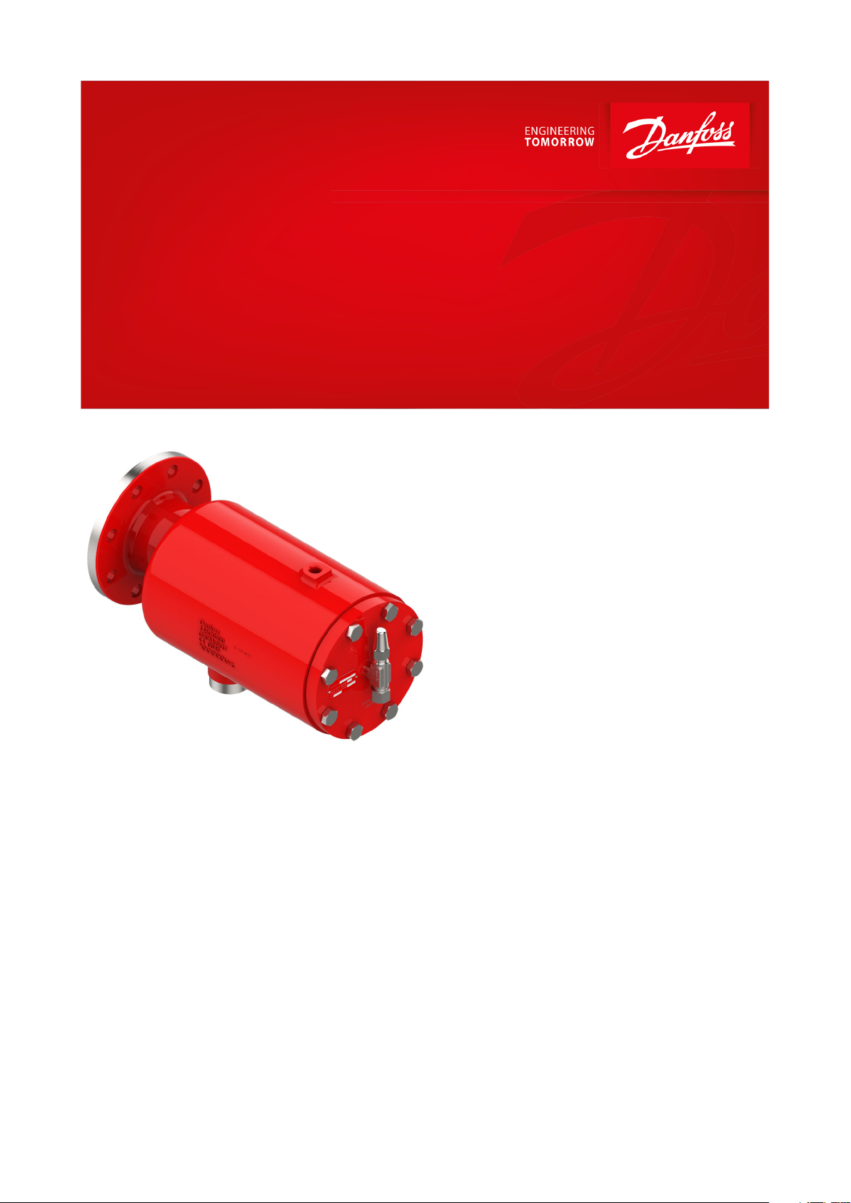
Float valve
Type HFI
Robust and reliable solution for high pressure control
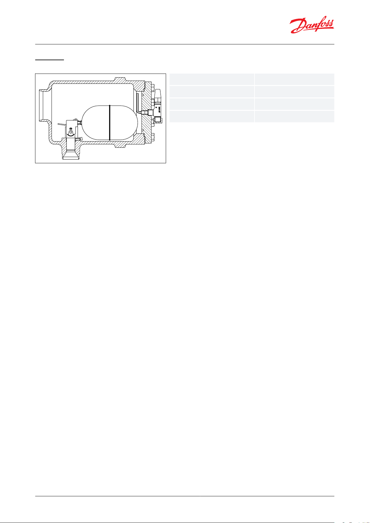
HFI is a high pressure oat valve with internal
liquid measuring device. The oat valve is
designed for direct ange mounting or welding
on to plate heat exchanger type condensers, as
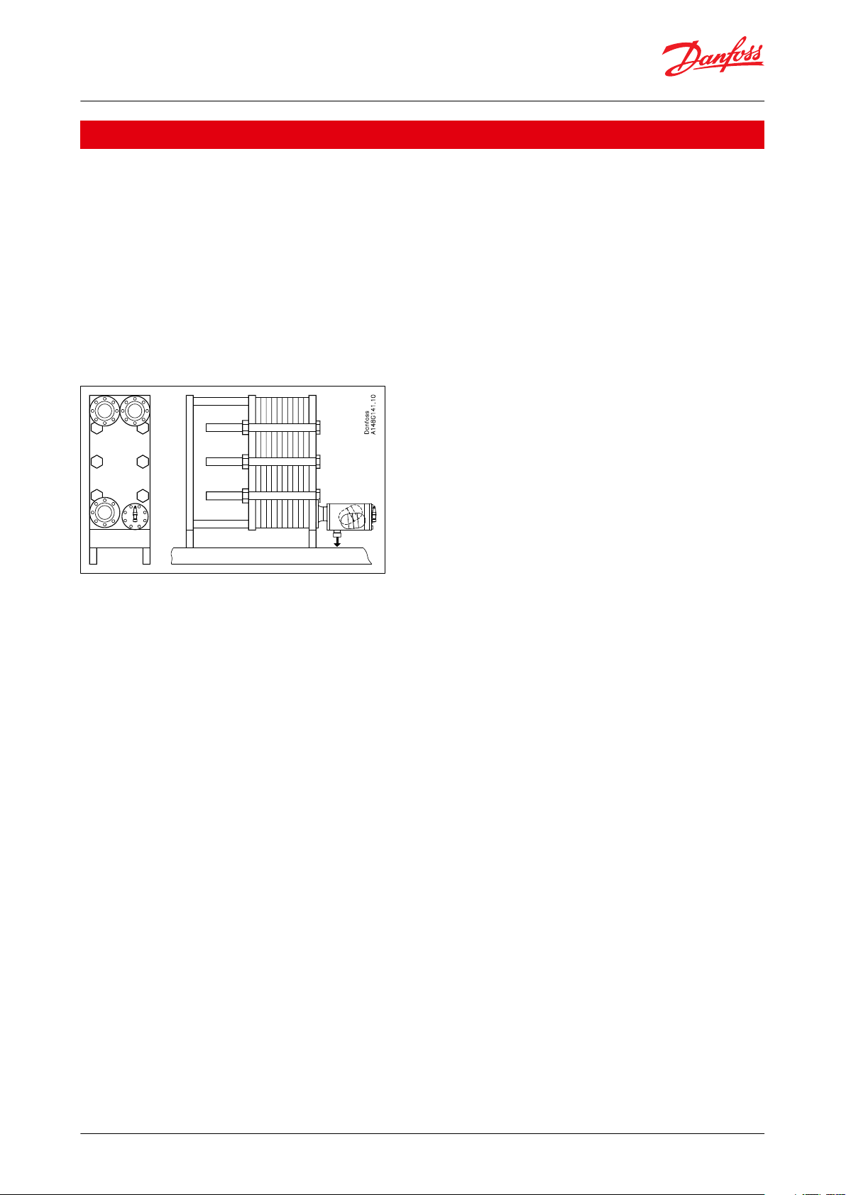
illustrated in Figure 1: Plate heat exchanger
HFI is direct acting, therefore no dierential
pressure is required to activate the valve.
HFI is robust and reliable due to its simple
design. The oat valve is equipped with a purge
valve for purging non condensable gases e.g.
air from the top of the valve housing. This
feature is also useful if the valve has to be
serviced.
The HFI is available with two external
connections on the housing for drainage and
pressure equalizations.
AI220786430153en-001101
Page 2
Float valve, type HFI
Features
• Designed for direct ange mounting on to plate heat exchanger type condensers
• Can be mounted directly on vessels
• Temperature range: -50 °C /+80 °C (-58 °F/+176 °F)
• Equipped with purge valve for purging non condensable gasses
• Available with external connections for drainage and pressure equalizations
• Maximum operating pressure is 25 bar (363 psig)
• Suitable for R717 (ammonia), HCFC and HFC with a density of 500 through 700 kg/m3 (31.21 - 43.70 lb/ft3). For
densities outside this range please contact your local Danfoss sales company.
• Housing i.e. shell and ange are made of special steel approved for low temperature application
• Classication: DNV, CRN, BV, EAC etc. To get an updated list of certication on the products please contact your
local Danfoss Sales Company.
Figure 1: Plate heat exchanger
© Danfoss | Climate Solutions | 2021.09 AI220786430153en-001101 | 2
Page 3

Float valve, type HFI
Media
Refrigerants
Refrigerants
Suitable for R717 (ammonia), HCFC and HFC with a density of 500 through 700 kg/m3 (31.21 - 43.70 lb/ft3). For
densities outside this range please contact your local Danfoss sales company.
Flammable hydrocarbons are not recommended. For further information please contact your local Danfoss Sales
Company.
New refrigerants
Danfoss products are continually evaluated for use with new refrigerants depending on market requirements.
When a refrigerant is approved for use by Danfoss, it is added to the relevant portfolio, and the R number of the
refrigerant (e.g. R513A) will be added to the technical data of the code number. Therefore, products for specic
refrigerants are best checked at store.danfoss.com/en/, or by contacting your local Danfoss representative.
© Danfoss | Climate Solutions | 2021.09 AI220786430153en-001101 | 3
Page 4
Description
Values
Temperature range
-50 °C / +80 °C (–58 °F /+176 °F)
The oat valve is designed for: Maximum operating pressure
Housing PED 28 bar (407 psig)
Ball (oat) 25 bar (363 psig)
Float valve, type HFI
Product specication
Design
Housing
Housing i.e. shell and ange is made of special steel approved for low temperature operation.
Installation
Refer to installation instruction for HFI.
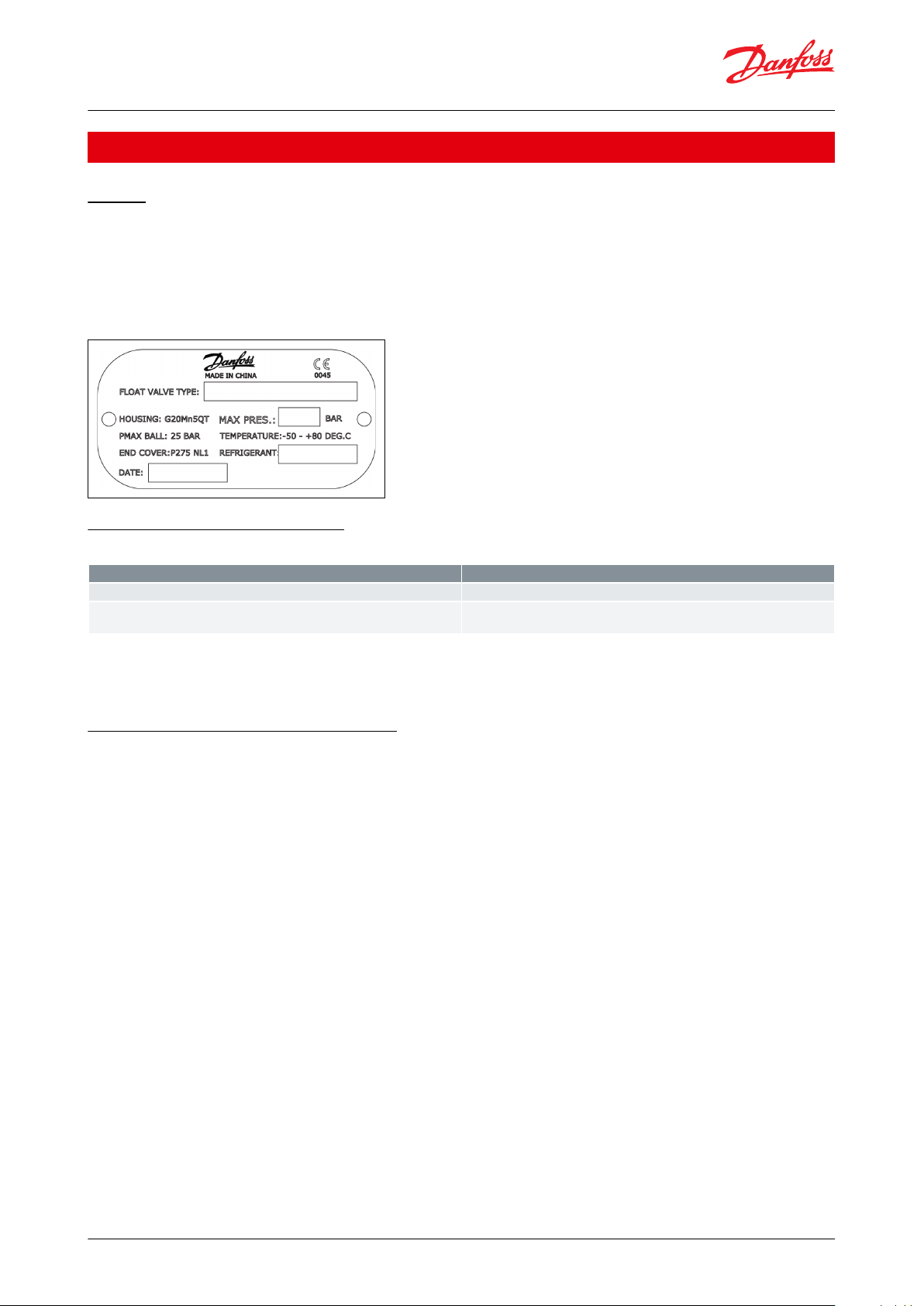
Figure 2: Identication:
Pressure and temperature data
Table 1: Pressure and temperature
If test pressure exceeds 25 bar (363 psi g) the ball should be removed during test.
Valves for higher pressure are available on request.
The principle of high pressure control
Introduction
In installations with one application high pressure control is an eective and cost saving way of expanding liquid
from the condenser to the low pressure side.
High pressure refrigerant entering the condenser will start to condense, consequently condensate will accumulate
at the bottom of the condenser and in the oat valve.
When capacity demands increase, the liquid level in the oat valve will rise, which will cause the valve to open and
the refrigerant to expand into the separator at the low pressure side.
When the valve is closed, there will still be a small by-pass over the seat, so any remaining liquid will equalize slowly
to the low pressure side, for instance during an o cycle. Therefore the system will equalize automatically and the
compressor can start up without excessive back pressure. The size of the bypass is predetermined and dened by
geometry of the elements.
It follows from the above, that almost all the refrigerant will be accumulated on the low pressure side under normal
conditions. Therefore under normal conditions no high pressure receiver is necessary when using the HFI for high
pressure control.
© Danfoss | Climate Solutions | 2021.09 AI220786430153en-001101 | 4
Page 5

ΔpρK
Valve type
Nominal capacity
[kW]
(R 717, –10/+35°C)
Valve constant [K]
HFI 040 FD
400
16.79
HFI 050 FD
800
33.58
HFI 060 FD
1200
50.36
HFI 070 FD
2400
100
dierential pressure [bar]
density of liquid [kg/m3]
valve constant (from the above table)
Condens‐
ing temp.
(°C)
Evaporating temperature (°C)
–40
–35
–30
–25
–20
–15
–10–505101520
50
45
40
35
475
460
440
420
480
460
440
420
480
460
440
420
475
460
440
415
475
455
435
415
475
455
430
405
470
445
425
400
460
440
415
390
455
430
405
375
445
420
390
360
430
405
375
340
415
385
350
315
395
360
325
280
30
25
20
15
400
380
360
340
400
380
355
335
400
375
355
330
395
370
350
325
390
365
340
315
385
360
330
300
375
345
315
285
360
330
300
265
345
315
280
240
325
290
250
200
300
260
210
150
270
220
155
230
160
10
5
0
–5
–10
315
290
270
245
220
310
285
260
235
210
305
280
255
225
200
295
270
240
210
180
285
255
225
190
155
270
240
205
165
115
250
215
175
120
225
185
125
195
135
140
Float valve, type HFI
Insert for the high pressure oat valve
Figure 3: Detail A Fully closed Figure 4: Detail B Fully open
Computation and selection
In R 717 plants (ammonia)
On the following pages you will nd tables with capacities of the oat valve at various operating conditions.
Select a valve using the specic operating conditions. The chosen valve must have a capacity higher than the
required capacity during nominal operation, as well as during plant start up.
In plants using other refrigerants than ammonia
The capacity of the oat valve can be calculated by using the values and the equation to the right. However, the
density of the refrigerant must be in the range: 500 to 700 kg/m3.
For densities outside this range please contact your local Danfoss Sales Company.
Table 2: Valve capacity values
Mass ow
G = K Δp × ρ
[kg / h]
Computation and selection capacity tables - SI units
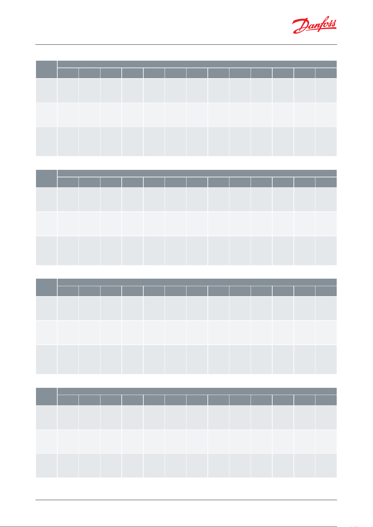
Table 3: HFI 040 - R 717, evaporating capacity [kW]
© Danfoss | Climate Solutions | 2021.09 AI220786430153en-001101 | 5
Page 6
Condens‐
ing temp.
(°C)
Evaporating temperature (°C)
–40
–35
–30
–25
–20
–15
–10–505101520
50
45
40
35
955
920
880
845
955
920
880
845
955
920
880
840
955
915
875
835
950
910
870
825
945
905
860
815
935
895
850
800
925
880
830
780
910
860
810
755
890
835
780
720
865
805
745
680
830
770
700
625
790
725
645
560
30
25
20
15
805
765
720
675
800
760
715
670
800
755
705
660
790
745
695
645
780
730
680
630
765
715
660
605
750
695
635
570
725
665
600
530
695
630
555
480
655
580
500
405
605
520
420
295
540
440
310
455
320
10
5
0
–5
–10
630
585
540
490
440
625
575
525
475
420
610
560
505
455
395
595
540
485
425
360
570
515
450
385
305
545
480
405
325
230
505
430
345
240
455
365
255
385
270
285
Condens‐
ing temp.
(°C)
Evaporating temperature (°C)
–40
–35
–30
–25
–20
–15
–10–505101520
50
45
40
35
1430
1380
1325
1265
1435
1380
1325
1265
1435
1380
1320
1260
1430
1375
1315
1250
1425
1370
1305
1240
1420
1360
1290
1220
1405
1340
1270
1200
1385
1320
1245
1170
1365
1290
1215
1130
1335
1255
1170
1080
1295
1210
1120
1020
1245
1155
1055
940
1190
1085
970
840
30
25
20
15
1205
1145
1080
1015
1205
1140
1070
1005
1195
1130
1060
990
1185
1115
1045
970
1170
1100
1020
940
1150
1075
990
905
1120
1040
950
860
1085
995
900
795
1040
940
835
715
980
870
750
605
905
780
635
445
810
660
465
685
485
10
5
0
–5
–10
945
875
805
735
660
935
860
785
710
635
915
840
760
680
595
890
810
725
635
540
860
770
675
575
460
815
720
610
490
340
755
645
520
360
680
550
380
580
405
425
Condens‐
ing temp.
(°C)
Evaporating temperature (°C)
–40
–35
–30
–25
–20
–15
–10–505101520
50
45
40
35
2445
2680
2545
2400
2775
2640
2490
2335
2725
2580
2425
2260
2665
2510
2340
2160
2590
2420
2235
2035
2495
2310
2105
1880
2375
2170
1940
1680
30
25
20
15
2090
1940
2340
2195
2040
1885
2300
2145
1980
1810
2245
2080
1900
1715
2170
1995
1800
1595
2080
1885
1670
1435
1960
1745
1500
1210
1815
1565
1265
890
1625
1320
930
1370
965
10
5
0
–5
–10
1470
1325
1725
1575
1425
1265
1835
1680
1520
1360
1190
1785
1620
1450
1270
1080
1715
1540
1350
1150
920
1630
1435
1220
980
685
1515
1295
1040
725
1365
1100
765
1160
810
850
Condens‐
ing temp.
(°F)
Evaporating temperature (°F)
–40
–30
–20
–10010203040506070
80
120
110
100
90
134
129
123
117
135
129
123
117
135
129
122
116
134
128
122
115
134
127
120
113
132
126
118
111
131
123
116
107
128
121
112
103
125
117
108
98
121
112
102
91
116
106
94
81
109
98
84
69
101
87
71
50
80
70
60
50
110
103
97
90
110
103
96
88
109
102
94
86
107
100
92
83
105
97
89
80
102
94
84
74
99
89
79
67
94
83
71
57
87
75
60
42
78
63
44
66
47
49
40
30
20
10
82
75
67
59
81
73
65
56
78
70
61
51
75
65
55
44
70
59
47
33
63
51
35
54
38
40
Float valve, type HFI
Table 4: HFI 050 - R 717, evaporating capacity [kW]
Table 5: HFI 060 - R 717, evaporating capacity [kW]
Table 6: HFI 070 - R717, evaporating capacity [kW]
Table 7: HFI 040 - R 717, evaporating capacity [TR]
© Danfoss | Climate Solutions | 2021.09 AI220786430153en-001101 | 6
Page 7

Condens‐
ing temp.
(°F)
Evaporating temperature (°F)
–40
–30
–20
–10010203040506070
80
120
110
100
90
268
258
246
234
269
258
246
233
269
257
245
232
269
256
243
229
267
254
241
226
265
251
237
221
261
247
232
215
256
241
224
207
250
233
215
196
242
224
204
181
231
211
189
163
218
195
169
138
201
175
143
101
80
70
60
50
221
207
193
179
220
206
191
176
218
203
188
172
215
200
184
167
211
194
177
159
205
187
169
149
197
178
157
134
187
166
142
114
174
149
121
84
156
127
89
132
93
97
40
30
20
10
165
150
135
119
161
145
129
112
156
139
121
102
149
130
110
88
140
118
95
65
127
102
70
108
75
80
Condens‐
ing temp.
(°F)
Evaporating temperature (°F)
–40
–30
–20
–10010203040506070
80
120
110
100
90
403
386
369
350
404
387
368
350
404
386
367
348
403
384
365
344
401
381
361
339
397
377
355
332
392
370
347
322
385
362
337
310
375
350
323
293
363
335
305
272
347
317
283
244
327
293
253
207
302
262
214
151
80
70
60
50
331
310
290
269
329
309
287
265
327
305
282
259
322
299
275
250
316
292
266
239
307
281
253
223
296
267
236
202
281
249
213
172
261
224
181
126
234
190
133
199
140
146
40
30
20
10
247
225
202
178
242
218
194
168
234
209
182
153
224
196
165
132
209
178
142
98
190
152
106
162
113
120
Condens‐
ing temp.
(°F)
Evaporating temperature (°F)
–40
–30
–20
–10010203040506070
80
120
110
100
90
678
710
664
784
741
695
645
769
723
673
620
750
700
646
587
725
671
611
544
694
633
566
489
654
586
507
413
603
524
428
302
80
70
60
50
517
599
551
500
632
583
532
477
615
562
506
446
592
534
472
403
561
497
426
343
521
447
362
253
469
380
267
397
279
292
40
30
20
10
404
357
483
436
387
336
469
418
364
307
448
391
331
263
419
355
284
195
380
305
211
325
226
240
Float valve, type HFI
Table 8: HFI 050 - R 717, evaporating capacity [TR]
Table 9: HFI 060 - R 717, evaporating capacity [TR]
Table 10: HFI 070 - R717, evaporating capacity [TR]
© Danfoss | Climate Solutions | 2021.09 AI220786430153en-001101 | 7
Page 8

Compressor
Vapor
Water chiller (evaporator)
Liquid
High pressure
Float Valve - HFI
High pressure
condenser
1
2
3
4
5
6
7
8
No
Part
Material
DIN/EN
ASTM
1
Housing
Steel
G20Mn5+QT
EN10213-3
2
Float Ball
Steel3Tube
Steel4Gasket
Aluminium
5
Gasket
Non asbestos
6
End cover with cylinder
Steel
PE275 NL1
EN 10028-3
7
Purge valve, SNV-ST
(1)
8
Set screw
Stainless steel
A2-70
Float valve, type HFI
High pressure control in refrigeration system with condenser/evaporator
Figure 5: A water chiller with plate heat exchanger as both condenser and evaporator. HFI is anged directly on to the
condenser.
Material specication
Figure 6: Housing parts
Table 11: Material specication
(1)
(1)
SNV-ST G½-G½ (148B3745).
SNV-ST G½-G½ (148B3745).
© Danfoss | Climate Solutions | 2021.09 AI220786430153en-001101 | 8
Page 9

OD
T
HFI size mm
HFI size in.
Outlet
For use with valve
type
ODmmTmmOD
in.Tin.
100460.3
2.9
2.37
0.11
HFI 040
HFI 050
HFI 060
HFI 070
150660.3
2.9
2.37
0.11
HFI 050
HFI 060
HFI 070
OD
T
HFI size mm
HFI size in.
Outlet
For use with valve
type
ODmmTmmOD
in.Tin.
100460.3
3.9
2.37
0.15
HFI 040
HFI 050
HFI 060
HFI 070
150660.3
3.9
2.37
0.15
HFI 050
HFI 060
HFI 070
OD
T
Float valve, type HFI
Connections
Available connections
Flange:
Inlet: Flange DN 100 or DN 150 (DIN-2635/DIN 2512-F)
Outlet: Welding connection DN 50 (EN 10220)
Butt-weld, DIN:
Inlet: DN 100 or DN 150 (EN 10220)
Outlet: Welding connection DN 50 (EN 10220)
Butt-weld, ANSI:
Inlet: DN 100 (4 in.) or DN 150 (6 in.) (ANSI B 36.10)
Outlet: Welding connection DN 50 (2 in.) (ANSI 36.10)
Figure 7: DIN - Outlet
Table 12: Butt-weld DIN (EN 10220)
Figure 8: ANSI - Outlet
Table 13: Butt-weld ANSI (B 36.10 Schedule 40)
Figure 9: DIN - Inlet
© Danfoss | Climate Solutions | 2021.09 AI220786430153en-001101 | 9
Page 10

HFI size mm
HFI size in.
Inlet
For use with valve
type
ODmmTmmOD
in.Tin.
1004114.3
3.6
4.50
0.14
HFI 040
HFI 050
HFI 060
HFI 070
1506168.3
4.5
6.63
0.18
HFI 050
HFI 060
HFI 070
OD
T
HFI size mm
HFI size in.
Inlet
For use with valve
type
ODmmTmmOD
in.Tin.
1004114.3
6.3
4.50
0.25
HFI 040
HFI 050
HFI 060
HFI 070
1506168.3
7.1
6.63
0.28
HFI 050
HFI 060
HFI 070
øDbøk
ød42ød
43
F
ød2
Z
Size 100 (4 in.)
mm
in.
235
9.3240.94
190
7.48
129
5.08
149
5.87
4.5
0.18220.97
8 pcs.
Size 150 (6 in.)
mm
in.
300
11.8281.10
250
9.84
183
7.20
203
7.99
4.5
0.18261.02
8 pcs.
Float valve, type HFI
Table 14: Butt-weld DIN (EN 10220)
Figure 10: ANSI - Inlet
Table 15: Butt-weld ANSI (B 36.10 Schedule 40)
Figure 11: Inlet ange
Table 16: 40 bar / DIN 2635 / DIN 2512-F*
*Inlet ange and DIN outlet
© Danfoss | Climate Solutions | 2021.09 AI220786430153en-001101 | 10
Page 11

B
A1
A3
A2
C
D
Fmin
Valve size
A1A2A3BC
ΦD
F
min
Weight
HFI 100
mm
in.
192
7.56
113
4.45250.98
280.5
11.05
440
17.32
227
8.94
200
7.87
43 kg
94.8 lb
HFI 150
mm
in.
167
6.57
113
4.45
280.5
11.05
440
17.32
227
8.94
200
7.87
43 kg
94.8 lb
B
A1
A3
A2
D
C
Fmin
Valve size
A1A2A3BC
ΦD
F
min
Weight
HFI 100
mm
in.
192
7.56
180
7.09250.98
280.5
11.05
506
19.92
227
8.94
200
7.87
49 kg
108 lb
HFI 150
mm
in.
167
6.57
189
7.44
280.5
11.05
506
19.92
227
8.94
200
7.87
49 kg
108 lb
Float valve, type HFI
Dimensions and weights
Figure 12: High pressure oat valve without ange
Table 17: High pressure oat valve without ange
NOTE:
Specied weights are approximate values only.
Figure 13: High pressure oat valve with ange
Table 18: High pressure oat valve with ange
NOTE:
Specied weights are approximate values only.
© Danfoss | Climate Solutions | 2021.09 AI220786430153en-001101 | 11
Page 12

B
A1
A3
A2
C
D
Fmin
E
A4
EXC1
EXC2
External Connections
EXC1
EXC2
⅜ - 18 NPT
½ - 14 NPT
B
A1
A3
A2
D
C
Fmin
E
A4
EXC1
EXC2
External Connections
EXC1
EXC2
⅜ - 18 NPT
½ - 14 NPT
Valve size
A1A2A3A4BCΦD
E
F
min
Weight
HFI 100
mm
in.
192
7.56
113
4.45250.98
176
6.93
280.5
11.05
440
17.32
227
8.94
247
9.72
200
7.87
43 kg
94.8 lb
HFI 150
mm
in.
167
6.57
113
4.45
176
6.93
280.5
11.05
440
17.32
227
8.94
247
9.72
200
7.87
43 kg
94.8 lb
Valve size
A1A2A3A4BCΦD
E
F
min
Weight
HFI 100
mm
in.
192
7.56
180
7.09250.98
176
6.93
280.5
11.05
506
19.92
227
8.94
251
9.88
200
7.87
49 kg
108 lb
HFI 150
mm
in.
167
6.57
180
7.09
176
6.93
280.5
11.05
506
19.92
227
8.94
247
9.72
200
7.87
49 kg
108 lb
Float valve, type HFI
Dimensions and weights (HFI with external connections)
Figure 14: High pressure oat valve without ange
Table 19: High pressure oat valve without ange
NOTE:
Specied weights are approximate values only.
Figure 15: High pressure oat valve with ange
Table 20: High pressure oat valve with ange
NOTE:
Specied weights are approximate values only.
© Danfoss | Climate Solutions | 2021.09 AI220786430153en-001101 | 12
Page 13
Internal volume (gross):
Internal volume with oat ball:
Liquid volume at max. level:
Liquid volume at min. level:
11.4 × 10⁻³ m3 (3.01 US
gal
)
9.6 × 10⁻³ m3 (2.54 US
gal
)
6.3 × 10⁻³ m3 (1.66 US
gal
)
3.6 × 10⁻³ m3 (0.95 US
gal
)
Float valve, type HFI
Volumes
Figure 16: Min. and Max. volumes
© Danfoss | Climate Solutions | 2021.09 AI220786430153en-001101 | 13
Page 14
Type
Inlet connection size
Nozzle size
Code numbers
HFI 040 FD 100
100 (4 in.) DIN Flange
40
148G3102
HFI 050 FD 100
50
148G3103
HFI 060 FD 100
60
148G3104
HFI 070 FD 100
70
148G3422
HFI 050 FD 150
150 (6 in.) DIN Flange
50
148G3105
HFI 060 FD 150
60
148G3106
HFI 070 FD 150
70
148G3423
HFI 040 D 100
100 (4 in.) DIN BW
40
148G3092
HFI 050 D 100
50
148G3093
HFI 060 D 100
60
148G3094
HFI 070 D 100
70
148G3418
HFI 050 D 150
150 (6 in.) DIN BW
50
148G3095
HFI 060 D 150
60
148G3096
HFI 070 D 150
70
148G3419
HFI 040 A 100
100 (4 in.) ANSI BW
40
148G3097
HFI 050 A 100
50
148G3098
HFI 060 A 100
60
148G3099
HFI 070 A 100
70
148G3420
HFI 050 A 150
150 (6 in.) ANSI BW
50
148G3100
HFI 060 A 150
60
148G3101
HFI 070 A 150
70
148G3421
Type
Inlet connection size
Nozzle size
Code numbers
HFI 040 FD 100 w. 2 ext. con
100 (4 in.) DIN Flange
40
148G3196
HFI 050 FD 100 w. 2 ext. con
50
148G3727
HFI 060 FD 100 w. 2 ext. con
60
148G3670
HFI 070 FD 100 w. 2 ext. con
70
148G3671
HFI 050 FD 150 w. 2 ext. con
150 (6 in.) DIN Flange
50
148G3762
HFI 060 FD 150 w. 2 ext. con
60
148G3763
HFI 070 FD 150 w. 2 ext. con
70
148G3764
HFI 040 D 100 w. 2 ext. con
100 (4 in.) DIN BW
40
148G3765
HFI 050 D 100 w. 2 ext. con
50
148G3704
HFI 060 D 100 w. 2 ext. con
60
148G3766
HFI 070 D 100 w. 2 ext. con
70
148G3720
HFI 050 D 150 w. 2 ext. con
150 (6 in.) DIN BW
50
148G3767
HFI 060 D 150 w. 2 ext. con
60
148G3768
HFI 070 D 150 w. 2 ext. con
70
148G3769
Type
Code numbers
Insert for HFI 070 (complete insert with
oat ball - without oat housing)
148G3584
Insert for HFI 060 ( complete insert with
oat ball - without oat housing)
148G3663
Insert for HFI 050 ( complete insert with
oat ball - without oat housing)
148G3662
Insert for HFI 040 ( complete insert with
oat ball - without oat housing)
148G3661
Float valve, type HFI
Ordering
The table below is used to identify the valve required.
Example: HFI 040 D 100 = 148G3092
Table 21: Type of inlet connection size and nozzle size
Table 22: HFI with 2 external connections
FD = inlet ange DIN
D = Butt welding DIN
A = Butt welding ANSI
Table 23: Connection types
© Danfoss | Climate Solutions | 2021.09 AI220786430153en-001101 | 14
Page 15

Danfoss
148B8106
Type
Connection type
Quantity
Code no.
Welding nipple incl. aluminium gasket
G½-ND6
2 pcs.
148B4184
Al gaskets included
¼” FPT – ½” G
1 pc.
148B3860
Al gaskets included
⅜” G - ½” G
1 pc.
148B3861
Float valve, type HFI
Accessories
Figure 17: Connection types
Table 24: Connection types
© Danfoss | Climate Solutions | 2021.09 AI220786430153en-001101 | 15
Page 16

The HFI-valves are approved in accordance with the European standard specied in the Pressure Equipment Directive and are CE marked.
HFI valves
Nominal bore
DN 100 and 150 mm (4 in. and 6 in.)
Classied for
Fluid group I
Catagory
III
File name
Document type
Document topic
Approval authority
RU Д-DK.БЛ08.В.00191_18
EAC Declaration
Machinery & Equipment
EAC
03709-F0 BV
Marine - Safety Certicate
-BVRU Д-DK.РА01.B.72054_20
EAC Declaration
PED
EAC
RU C-DK.БЛ08.B.01093_20
Pressure - Safety Certicate
PED
EAC
033F0685.AK
EU Declaration
EMCD/PED
Danfoss
033F0691.AE
Manufacturers Declaration
RoHS
Danfoss
0045 202 1204 Z 00355 19 D 001(00)
Pressure - Safety Certicate
-
TÜV
033F0473.AD
Manufacturers Declaration
ATEX
Danfoss
19.10327.266
Marine - Safety Certicate
-
RMRS
Float valve, type HFI
Certicates, declarations, and approvals
The list contains all certicates, declarations, and approvals for this product type. Individual code number may have
some or all of these approvals, and certain local approvals may not appear on the list.
Some approvals may change over time. You can check the most current status at danfoss.com or contact your local
Danfoss representative if you have any questions.
Table 25: Pressure Equipment Directive (PED)
For further details / restrictions - see Installation Instruction
Table 26: Valves specications
Table 27: Certicates and declarations
© Danfoss | Climate Solutions | 2021.09 AI220786430153en-001101 | 16
Page 17

Online support
Danfoss oers a wide range of support along with our products, including digital product information, software,
mobile apps, and expert guidance. See the possibilities below.
The Danfoss Product Store
The Danfoss Product Store is your one-stop shop for everything product related—no matter where
you are in the world or what area of the cooling industry you work in. Get quick access to essential
information like product specs, code numbers, technical documentation, certications, accessories,
and more.
Start browsing at store.danfoss.com.
Find technical documentation
Find the technical documentation you need to get your project up and running. Get direct access to
our ocial collection of data sheets, certicates and declarations, manuals and guides, 3D models
and drawings, case stories, brochures, and much more.
Start searching now at www.danfoss.com/en/service-and-support/documentation.
Danfoss Learning
Danfoss Learning is a free online learning platform. It features courses and materials specically
designed to help engineers, installers, service technicians, and wholesalers better understand the
products, applications, industry topics, and trends that will help you do your job better.
Create your Danfoss Learning account for free at www.danfoss.com/en/service-and-support/learning.
Get local information and support
Local Danfoss websites are the main sources for help and information about our company and
products. Find product availability, get the latest regional news, or connect with a nearby expert—all
in your own language.
Find your local Danfoss website here: www.danfoss.com/en/choose-region.
Spare Parts
Get access to the Danfoss spare parts and service kit catalog right from your smartphone. The app
contains a wide range of components for air conditioning and refrigeration applications, such as
valves, strainers, pressure switches, and sensors.
Download the Spare Parts app for free at www.danfoss.com/en/service-and-support/downloads.
Coolselector®2 - nd the best components for you HVAC/R system
Coolselector®2 makes it easy for engineers, consultants, and designers to nd and order the best
components for refrigeration and air conditioning systems. Run calculations based on your operating
conditions and then choose the best setup for your system design.
Download Coolselector®2 for free at coolselector.danfoss.com.
Any information, including, but not limited to information on selection of product, its application or use, product design, weight, dimensions, capacity or any other
technical data in product manuals, catalogues descriptions, advertisements, etc. and whether made available in writing, orally, electronically, online or via download,
shall be considered informative, and is only binding if and to the extent, explicit reference is made in a quotation or order conrmation. Danfoss cannot accept any
responsibility for possible errors in catalogues, brochures, videos and other material. Danfoss reserves the right to alter its products without notice. This also applies to
products ordered but not delivered provided that such alterations can be made without changes to form, t or function of the product. All trademarks in this material
are property of Danfoss A/S or Danfoss group companies. Danfoss and the Danfoss logo are trademarks of Danfoss A/S. All rights reserved.
© Danfoss | Climate Solutions | 2021.09 AI220786430153en-001101 | 17
 Loading...