

Data sheet
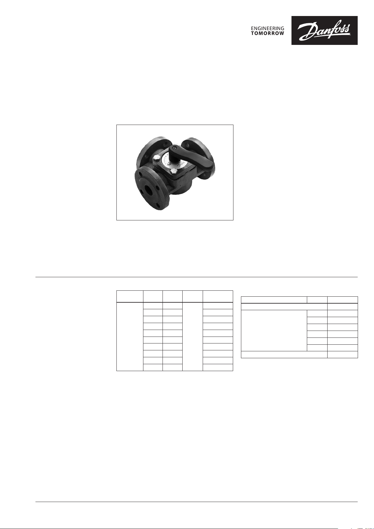
Rotary valves HFE 3
Description
Ordering
Danfoss HFE rotary valves are primarily designed
for regulation of flow temperature in heating
systems where a certain leakage can be accepted
and where a defined control characteristic is not
required.
Typ e
HFE 3
DN
(mm)
20 12
25 18 065Z0429
32 28 065Z0430
40 44 065Z0431
50 60 065Z0432
65 90 065Z0433
80 15 0 065Z0434
100 225 065Z0435
125 280 065Z0436
150 400 065Z0437
k
VS
(m3/h)
PN Code No.
065Z0428
6
HFE rotary valves can be used in combination
with electric actuators AMB 162 and AMB 182.
Features:
• Cast iron body with flange connection
• Lowest leakage in class
• Valve position indicator
• Ergonomic handle
• For mixing and diverting applications
• Flange PN 6 connection
Main data:
• DN 20–150
• kVS 12– 400 m3/h
• PN 6
• t
110 °C
max
• 3-way
• S characteristic
Spare parts and accessories
Typ e DN Code No.
Replacement handle 065Z0443
20-25 065Z0454
32-40 065Z0455
Stuffing box and sealing
Linkage kit for AMB (Gen. 2014) 082H0255
50-65 065Z0456
80 065Z0457
100-125 065Z0458
150 065Z0459
© Danfoss | 2019.10 VD.LH.A5.02 | 1
Data sheet Rotary valves HFE 3
Technical data
Pressure temperature
diagram
Nominal diameter DN 20 25 32 40 50 65 80 100 125 15 0
k
VS
Control characteristic S characteristic
Leakage Diverting: max. 0.75% of kVS / Mixing: max. 1.5% of k
Nominal pressure PN 6
Max. closing pressure bar 0.5
Torque at PN Nm 5 10 15
Medium Circulation water / glycolic mixture up to 50%
Medium pH Min. 7, max. 10
Medium temperature °C 2 … 110
Connections Flanges PN 6
Materials
Valve body and cover Grey cast iron EN-GJL-250 (GG25)
Slide shoe CuZn36Pb2As (BrassDZR, CW 602N)
Stuffing box sealing EPDM
m3/h 12 18 28 44 60 90 15 0 225 280 400
VS
Stainless steel,
EN 1.4301 (304)
PN 6
EN-GJL-250
(GG-25)
Installation
110
Valve mounting
Before valve mounting pipes have to be cleaned
and free from abrasion. Mechanical loads on
valve body caused by the pipes are not allowed.
It is recommended to install a strainer into
application to avoid damaging controlling
components.
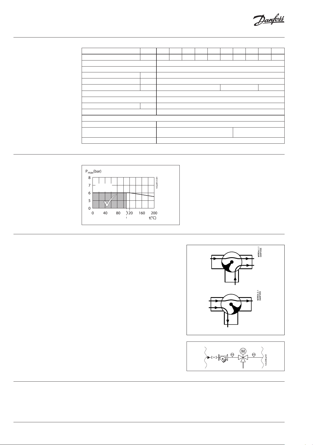
Connection
HFE 3 can be used as a mixing valve, diverting
valve and in connection with heat exchangers
where a certain leakage can be accepted.
Note:
Install a strainer upstream of the valve
(e.g. Danfoss FVR/FVF)
Mixing
Diverting
AMB
FVR/FVF
Disposal
The valve must be dismantled and the elements
sorted into various material groups before
disposal.
2 | VD.LH.A5.02 © Danfoss | 2019.10

Data sheet Rotary valves HFE 3
Application principles
Sizing
HFE 3 mixing function
HFE 3 diverting function
HFE 3 diverting function
Reverse function can be achieved by changing
motor rotation direction (Valve label must also be
turned round). See further details in valve and motor
instructions.
Flow Rate
(liquid w ith specific a gravi ty of 1)
l/sec m3/h
FLOW Pressure drop kPa (100 kPa = 1bar = ~ 10 m H2O)
max
Δp
VD.LH.A5.02 | 3© Danfoss | 2019.10

Danfos
produc
Al
Danfoss A/S
Heating Segment
Data sheet Rotary valves HFE 3
Design
1. Valve body
2. Slide shoe
3. Valve cover
4. Stuffing box
5. Handle
Dimensions
106
n
1
H
H
L
1
B
K
1
L
фd
40
79
1
L
L
L
DN
20 137 92 14 0 131 140 70 45 65 11. 5 4 3.5
25 142 92 14 0 136 150 75 50 75 11. 5 4 4.0
32 158 98 152 14 6 160 80 60 90 15 4 6.6
40 163 98 15 7 146 175 88 65 100 15 4 7. 2
50 177 107 171 155 19 5 98 70 110 15 4 9.4
65 187 107 181 155 200 100 80 130 15 4 11. 5
80 215 120 208 167 235 118 95 15 0 18 4 17
100 233 128 228 177 265 133 105 170 18 4 22.5
125 259 13 9 253 187 300 15 0 120 200 18 8 29.5
150 277 145 271 192 350 175 133 225 18 8 40.2
H H
H
H
1
2
L L
3
mm
B K фd
1
Weight
n
(kg)
Actuator
AMB 162
AMB 182
90
75
92
H
3
H
2
s can accept no responsibility for possible errors in catalogues, brochures and o ther printed material. Danfoss reserves the right to alter its pro ducts without notice. This also applies to
ts already on order provided that such alterations can be m ade without subsequential changes being necessary in specications already agreed.
l trademarks in this material are property of the r espective companies. Danfoss and all Danfoss logot ypes are trademarks of Danfoss A/S. All rights reserved.
• heating.danfoss.com • +45 7488 2222 • E-Mail: heating@danfoss.com
© Danfoss | DHS-SDBT/SI | 2019.104 | VD.LH.A5.02
 Loading...