

Page 1

Installation Guide
Heating mats
Thin concrete < 3 cm
electricheating.danfoss.com
Page 2
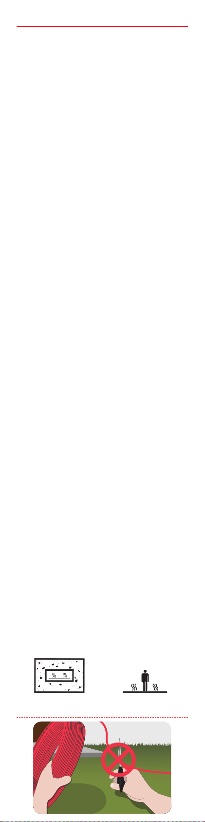
Table of Contents
1.1 Sikkerhedsinstruktioner . . . . . . . . . . . .2
1.2 Installationsvejledning . . . . . . . . . . . .4
2 Installation, trin for trin . . . . . . . . . . . . .5
2.1 Beregning af indbyrdes kabelafstand . . .5
2.2 Planlægning af installationen . . . . . . . .5
2.3 Klargøring af installationsstedet. . . . . . .6
3 Installation af elementer . . . . . . . . . . . . 6
3.1 Installation af varmeelementer . . . . . . .7
3.2 Følerinstallation . . . . . . . . . . . . . . . . .7
4 Indendørs anvendelser. . . . . . . . . . . . . . 8
4.1 Gulvvarme i tynde gulve (< 3 cm . . . . . .8
5 Valgfrie indstillinger . . . . . . . . . . . . . . . 9
1 Introduction
In this installation manual, the word “element” refers
to both heating cables and heating mats.
If the words “heating cable” or “heating mat” are
used, the instruction in question applies only to this
type of element.
All dimensioning, product selection, installation
and commissioning of any given application are the
responsibility of an authorized installer.
Any application using heating elements or thermostats purchased by end user must be approved by an
authorized electrician prior to commissioning.
• Including type, size, installation and connection
of the heating element.
• Including type, size, connection and settings
of the thermostat controlling the heating
element.
• Children shall not play with the heating
element.
• This heating element can be used by children
aged from 8 years and above and persons with
reduced physical, sensory or mental capabilities
or lack of experience and knowledge if they
have been given supervision or instruction
concerning use of the appliance in a safe way
and understand the hazards involved.
• Cleaning and user maintenance shall not be
made by children without supervision.
The intended use of the heating elements covered
by this installation manual is oor heating, only.
• According to IEC 60335 the mats may not be
installed in a metallic oor or storage heating
application.
• Mats shall be fully embedded in at least 5 mm
concrete, screed, tile adhesive or similar. incl.
tiles.
1.1 Safety Instructions
Page 3

Never cut or shorten the heating element
!
1
2
3
4
5
6
7
• Cutting the heating element will void the
warranty.
• Cold leads can be shortened to suit requirements.
Elements must always be installed according to
local building regulations and wiring rules as well
as the guidelines in this installation manual.
• Any other installation may hamper element
functionality or constitute a safety risk, and will
void the warranty.
Elements must always be connected by an authorised electrician using a xed connection.
• De-energize all power circuits before installation and service.
• Each heating element screen must be earthed
in accordance with local electricity regulations
and connected to a residual current device
(RCD).
• RCD trip rating is max. 30 mA.
• Heating elements must be connected via a
switch providing all pole disconnection.
• The element must be equipped with a correctly
sized fuse or circuit breaker according to local
regulations.
1. Heating cable
2. Thermostat
3. Sensor
4. Screen
5. RCD
6. All-pole switch
7. Fuse
The presence of a heating mat must
• be made evident by axing caution signs or
markings at the power connection ttings and/
or frequently along the circuit line where clearly
visible
• be stated in any electrical documentation
following the installation.
Connections
• Phase - Brown
• Neutral - Blue
• Earth - Screen
Page 4

Never exceed the maximum heat density (W/m)
for the actual application.
1.2 Installation guidelines
Prepare the installation site properly by removing
Regularly measure ohmic resistance and insula-
tion resistance before and during installation.
Do not lay heating elements under walls and xed
sharp objects, dirt, etc.
obstacles. Min. 6 cm air is required.
Keep elements clear of insulation material, other
heating sources and expansion joints
Elements may not touch or cross themselves or
other elements and must be evenly distributed
The elements and especially the connection must
be protected from stress and strain.
on areas.
The elements and sensors shall be installed minimum 30 mm away from conductive parts of the
building, e.g. water pipes.
Page 5

A oor sensor is mandatory and must be connect-
ed to a thermostat limiting the oor temperature
The element should be temperature controlled
and not operate at ambient temperature higher
to maximum 35°C.
than 10°C in outdoor applications.
2 Installation step by step
2.1 C-C distance for heating cables
The C-C distance is the distance in centimetres from
the centre of one cable to the centre of the next.
C - C [cm] =
or
C - C[cm] =
• Max. C-C distance for thin beddings (<3 cm)
is10 cm.
• Heating cable bending diameter must be at
least 6 times cable diameter.
• The actual cable length may vary +/- 2 %.
C-C [cm] 5 7.5 10 12.5 15
W/m2 @ 6 W/m 120 80 60 48 40
W/m2 @ 10 W/m 200 130 100 80 67
W/m2 @ 18 W/m - - 180 144 120
W/m2 @ 20 W/m - - 200 160 133
2.2 Planning the installation
Draw a sketch of the installation showing
• element layout
• cold leads and connections
• junction box/cable well (if applicable)
• sensor
• connection box
• thermostat
Area [m]
Cable length [m]
Cable output [W/m]
Heat density [W/m]
230V/400V
x 100 cm
x 100 cm
Page 6

Save the sketch
• Knowing the exact location of these components makes subsequent troubleshooting and
repair of faulty elements easier.
Please the following:
• Observe all guidelines - see section 1.2 .
• Observe correct C-C distance (heating cables
only) - see section 2.1.
• Observe required installation depth and
possible mechanical protection of cold leads
according to local regulations.
• When installing more than one element, never
wire elements in series but route all cold leads
in parallel to the connection box.
• Two or more elements may be installed in
the same room but a single element is not
to be installed across two or more rooms.
• All heating elements in the same room must
have the same heat density (W/m) unless
they are connected to separate oor sensors
and thermostats.
• For single conductor cables, both cold leads
must be connected to the connection box.
2.3 Preparing the installation area
• Remove all traces of old installations, if applicable.
• Ensure that the installation surface is even,
stable, smooth, dry and clean.
• If necessary, ll out gaps around pipes,
drains and walls.
• There must be no sharp edges, dirt or foreign
objects.
3 Installing elements
It is not recommended to install elements at temperatures below -5 °C.
At low temperatures, heating cables can become
rigid. After rolling out the element, briey connect
it to the mains supply to soften the cable before
fastening.
Measuring Resistance
Measure, verify and record element resistance during installation.
• After unpacking
• After fastening the elements
• After the installation in nalized
If ohmic resistance and insulation resistance are not
as labelled, the element must be replaced.
Page 7

• The ohmic resistance must be within -5 to +10
% of the value labelled.
• The insulation resistance should read >20 M
after one minute at min. 500V DC..
3.1 Installing heating elements
Observe all instructions and guidelines in section 1.1
and 1.2.
Heating elements
• Position the heating element so that it is at
least half the C-C distance from obstacles.
• Elements must always be in good contact with
the heat distributor (e.g. concrete), see section
4 for details.
Heating mats
• Always roll out heating mats with the heating
cables facing up.
• When the heating mat reaches the area boundary, cut the liner/net and turn the mat before
rolling it back.
Extending cold leads
• Avoid extending cold leads if possible. Wire
cold leads to e.g. junction boxes or cable wells.
• Be aware of power loss in the cable according
to local regulations.
3.2 Sensor Installation
• Mandatory under wooden oors and on wooden sub oors.
• The oor sensor should be mounted in an insulating conduit, sealed at the oor end, for easy
replacement of the sensor if required.
• The oor sensor must be considered a LIVE cable; therefore any extension made to the sensor
wiring should be treated in the same way as
normal mains voltage cabling.
• The sensor can be extended up to a total of 50
m using 1.5 mm installation cable.
• The minimum bending radius for the pipe is 50
mm (1).
• The sensor cable must be placed between two
loops of the heating cable (2).
• To avoid cracks in the concrete oor do not
switch on the heat until the oor has completely hardened.
Page 8

12
≥
• The conduit should be ush with the sub oor.
1
2
1
234
567
• Route the conduit to the connection box.
4 Indoor applications
Suboor
Wood -
Concrete Max. 200 W/m
Floor types
Wood, parquet, laminate Maks. 150 W/m
Carpet, vinyl, linoleum, etc. Maks. 150 W/m
Tiled oors in bathrooms
conservatories cellars, etc.
Tiled oors in kitchens
living rooms halls, etc.
May be up to 225 W/m in rim zones e.g. under large
windows.
• On concrete sub oors and under tiles, only.
• If connected to a separate oor sensor and
thermostat.
Wooden oor coverings
Wood shrinks and swells naturally depending on the
relative humidity (RH) in the room.
100 - 200 W/m
100 - 150 W/m
• Avoid beech and maple in multilayered oor
coverings unless press dried.
• Install a vapour barrier for sub oors <95% RH
and a damp proof membrane >95%.
• Ensure 100% contact between the element and
the embedding material above (no air pockets).
• Install the heating system in the whole oor
area at 15°C surface temperature.
• Always install a oor sensor to limit the max.
oor temperature.
4.1 Floor heating in thin beddings
New tiles on existing tiles, concrete oors or
wooden oors
1. New tiles.
2. Tile adhesive.
3. Vapour barrier.
4. Self-levelling compound.
5. Heating element.
6. Primer (on concrete) or screed (on wood).
7. Existing tiles, concrete or wooden oor.
Page 9

New oor covering on existing tiles, concrete
5
4
1
2
3
6
7
oors or wooden oors
1. Wooden oor, laminate or carpet.
2. Noise absorption mat.
3. Vapour barrier.
4. Self-levelling compound.
5. Heating mat or heating cable.
6. Primer (on concrete) or screed (on wood).
7. Existing tiles, concrete or wooden oor.
Wooden sub oors must be properly anchored
• Apply screed before laying the heating element.
Vapour barrier
• Apply only if not already installed in existing
oor.
• In wet rooms apply only above the heating
elements.
Tile adhesive or self-levelling compound
• Prime the sub oor as specied by the supplier.
• The heating element should be securely fastened before applying.
• The heating element must be fully embedded
and at least 5 mm.
Installation summary
Cut out a wall groove and x cable ducts and
connection box. Chisel o a groove for the sensor
conduit and cold cable. Fix the sensor conduit e.g.
with a glue gun.
Roll out the element. Attach it to the sub oor. Cut
and turn the mat mesh when meeting walls or
obstacles. Do NOT cut the heating elements.
Apply exible self-levelling compound, vapour
barrier, and tile adhesive, depending on the oor
nish.
5 Optional settings
If the element is connected to a thermostat such
as a ECtemp, congure basic settings according to
the table below and as described in the thermostat
installation manual.
Page 10

If applicable, adjust the temperature limit in accordance with the manufacturer’s recommendations in
order to prevent damage to e.g. the oor or the pipe.
Thermostat Max. load
ECtemp 13x 16A
ECtemp 330 16A
ECtemp 53x 15A
ECtemp 610 10A
ECtemp Touch 16A
Danfoss link CC 15A (FT)
Floor heating
in general
Room temp.
20-22° C.
VIKZB102
 Loading...