

Page 1
Operating Guide
Electronic Heat Cost Allocator
Table of Contents 1. General ..................................................................................................................................... 3
1.1 Application.......................................................................................................................................................... 3
1.2 General Guidelines........................................................................................................................................... 3
1.2.1 Hazards and Disposal .............................................................................................................................. 3
1.2.2 Changing the Battery .............................................................................................................................. 3
1.2.3 Installation with Glue .............................................................................................................................. 3
1.2.4 Warranty ....................................................................................................................................................... 3
1.2.5 Compliant Use ............................................................................................................................................ 3
1.2.6 Non-compliant Use .................................................................................................................................. 3
1.2.7 Notes regarding Installation ................................................................................................................. 3
1.2.8 Protection against Outside Influences.............................................................................................. 3
1.2.9 Data Collection while the Device is open ........................................................................................ 4
1.2.10 Transport in Original Packaging .......................................................................................................... 4
1.2.11 New Programming ................................................................................................................................... 4
1.3 Restrictions ......................................................................................................................................................... 4
1.3.1 Applications ................................................................................................................................................ 4
1.3.2 Measurement using Single or Dual Sensors ................................................................................... 4
1.3.3 Exclusion of Liability ................................................................................................................................ 4
1.3.4 Modifications .............................................................................................................................................. 4
2. Product Description ................................................................................................................ 4
2.1 Packaging ........................................................................................................................................................... 4
2.2 General Description ........................................................................................................................................ 4
2.2.1 Type ................................................................................................................................................................ 4
2.2.2 Design ........................................................................................................................................................... 4
2.2.3 Characteristics ............................................................................................................................................ 5
2.2.4 Display ...........................................................................................................................................................5
2.2.5 Electronics ................................................................................................................................................... 5
2.2.6 Versions......................................................................................................................................................... 5
2.2.7 Optical Interface ........................................................................................................................................ 6
2.2.8 Radio Wireless M-Bus .............................................................................................................................. 6
2.3 Technical data .................................................................................................................................................... 6
3. Settings .................................................................................................................................... 7
3.1 Settings ................................................................................................................................................................ 7
3.2 Operating mode ............................................................................................................................................... 9
3.2.1 Cycle ............................................................................................................................................................... 9
© Danfoss | 2019.03 VU.SH.H1.02 | 1
Page 2

Operating Guide SonoHCA
Table of Contents
(continuous)
3.2.2 Single Sensor Version with Start Sensor ........................................................................................... 10
3.2.3 Dual Sensor Version ................................................................................................................................. 10
3.2.4 Comparison of the Measuring Principles ......................................................................................... 10
3.2.5 Temperature Measurement and Calculation .................................................................................. 10
3.2.6 Calculation of the Displayed Consumption Value ........................................................................ 11
3.2.7 Start of Counting ....................................................................................................................................... 11
3.3 Display and Additional Functions .............................................................................................................. 12
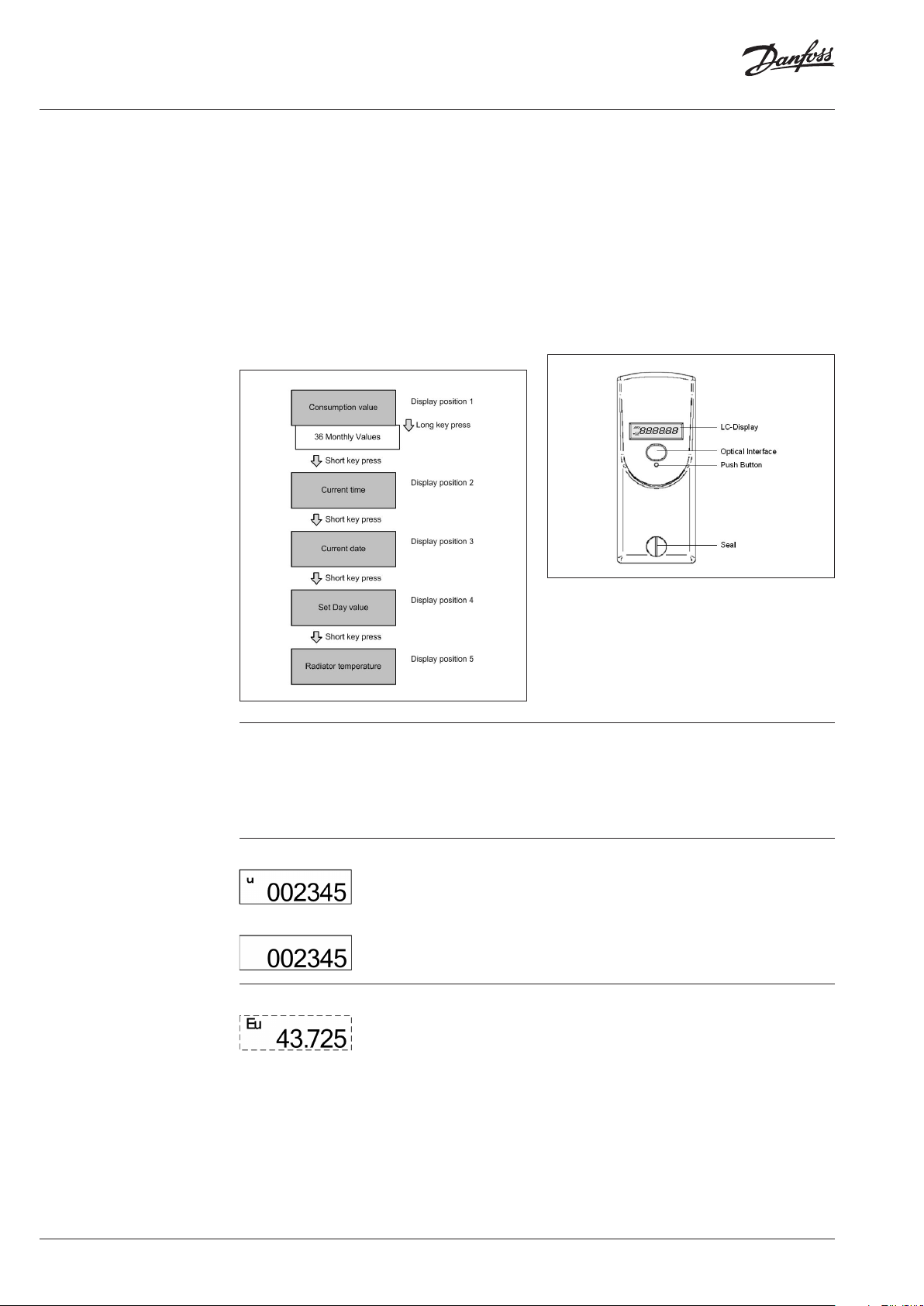
3.3.1 The Menu Sequences of the Digital Display................................................................................... 12
3.3.2 The Digital Display ................................................................................................................................... 12
3.3.3 Rolling Display ........................................................................................................................................... 15
3.3.4 Communication Indicator and Measuring Indicator • .......................................................... 16
3.3.5 Real Time Clock and Calendar ............................................................................................................. 16
3.3.6 Check code.................................................................................................................................................. 16
3.4 Special Functions ............................................................................................................................................. 17
3.4.1 Suppression of Summer Counting ..................................................................................................... 17
3.4.2 Annual Reset of the Consumption Value ......................................................................................... 17
3.4.3 Unit Scale and Product Scale ................................................................................................................ 17
3.5 Parameterization .............................................................................................................................................. 17
3.6 Error ....................................................................................................................................................................... 17
3.6.1 List of Errors ................................................................................................................................................. 17
4. Installation ............................................................................................................................... 18
4.1 Introduction ....................................................................................................................................................... 18
4.2 DIN Standard Requirements for the Installation .................................................................................. 18
4.3 General Restrictions ........................................................................................................................................ 18
4.4 Operating Range .............................................................................................................................................. 18
4.5 Allocator Installation Position – Standard Installation ....................................................................... 19
4.6 Mounting the Remote Sensor ..................................................................................................................... 20
4.7 Wall Mounting ................................................................................................................................................... 21
4.8 Installation of Fastening Parts Kits ............................................................................................................ 22
4.8.1 Installation to Sectional Radiator, direct mounting ..................................................................... 22
4.8.2 Sectional Radiator, wall mounting ..................................................................................................... 22
4.8.3 Installation on Folded Radiator ........................................................................................................... 23
4.8.4 Folded Radiator, wall mounting .......................................................................................................... 23
4.8.5 Installation to Panel Type Radiator ..................................................................................................... 24
4.8.6 Mounting of heat cost allocators with glue .................................................................................... 24
4.8.7 Panel Type Radiator, wall mounting .................................................................................................. 25
4.8.8 Installation to Panel-Type Radiator with Front Convection Plate ........................................... 25
4.8.9 Bathroom radiator – Towel rails ........................................................................................................... 26
4.8.10 Sectional Radiator wide .......................................................................................................................... 27
4.9 Overview mounting accessories ................................................................................................................ 27
4.10 Mounting and Sealing .................................................................................................................................... 28
5. Commissioning ........................................................................................................................28
5.1 Automatic commissioning during the installation.............................................................................. 28
5.2 Commissioning by pressing push button .............................................................................................. 29
5.3 Radio Standby ................................................................................................................................................... 29
5.3.1 Sleeping Mode ........................................................................................................................................... 30
5.3.2 Installation Mode ...................................................................................................................................... 30
5.3.3 Operation Mode ........................................................................................................................................ 30
6. Readout .................................................................................................................................... 30
6.1 Remote Radio Reading .................................................................................................................................. 31
6.1.1 General Information about the Remote Radio Readout............................................................. 31
6.1.2 WireIess M-Bus Remote Radio Readout ............................................................................................ 31
6.1.3 Readout using the Radio Central SonoCollect ............................................................................... 31
7. Rating factors ..........................................................................................................................32
7.1 Taking Measurements ..................................................................................................................................... 32
7.1.1 Rating of Radiators with Over Length or High Nominal Power ............................................... 32
7.1.2 Rating of Radiator ..................................................................................................................................... 32
7.2 Table of Rating Factors ................................................................................................................................... 33
7.3 Rating Factor according EN 834:2013 ........................................................................................................ 33
2 | VU.SH.H1.02 © Danfoss | 2019.03
Page 3
Operating Guide SonoHCA
1. General
This manual serves as a reference for users
and service personnel of the Danfoss heat cost
1.1 Application
allocators. It describes the use of the SonoHCA
heat cost allocators.
The heat cost allocator is a measuring device
to record the heat output of radiators in units.
Units are apartments, offices, and business,
commercial or industrial premises whose heat is
supplied through a central heating system or via
a conjoint district heating station.
The group of units constitutes one billing unit.
If one billing unit includes units with differences,
for example, from a technical standpoint (in
the form of different heating systems) or in
terms of consumption behaviour (i.e. in the
case of industrial premises and apartments), a
subdivision of the billing units into unit groups
may be necessary.
Each radiator is fitted with a heat cost allocator
which records and assesses the heat output of
the radiator and displays the consumption value.
1.2 General Guidelines 1.2.1 Hazards and Disposal
The heat cost allocators a re equipped with
respect the transpor t directives applicable in yo ur
coun try.
lithium batteries . This type of batte ry falls into
the category of ha zardous goods. Please
Handling of Lithium Batteries:
• Store in a dry place.
• Do not heat to more than 100°C and do not
throw into a fire.
• Do not store near a heat source.
• Do not store in direct sunlight.
• Do not short-circuit.
• Do not open or damage.
• Do not recharge.
• Keep out of reach of children.
1.2.2 Changing the Battery
The heat cost allocator’s battery is soldered.
Changing the battery is neither provided for nor
permitted.
Disposal
In order to protect the e nvironment, to
reduce waste of natural resources and
prevent pollution, the European Uni on
has adopted a directive stipulating
that electric al and electronic devices must be
recovered by their manufac turers in order to
ensure proper destruction or recycling.
Should you dispose of the device yourself, please
get information from your local authority on
recycling options.
The consumption value is the basis for allocating
the heating costs to each unit, which is necessary
for the annual billing of the heating costs.
The heat cost allocators are principally used in
the following units:
• Collective housing buildings.
• Offices or administrative buildings.
The typical users are:
• Measuring and billing services.
• Cooperatives or property managers.
• Building service companies, letting agencies.
The heat cost allocators can be installed on:
• Sectional radiators.
• Column/tube radiators.
• Panel radiators with horizontal or vertical
water flow.
• Flat register radiators.
• Convector heaters.
1.2.4 Warranty
The warranty rights are only valid if the devices
have been installed and used in compliance with
regulations and if the technical guidelines in
force have been followed.
1.2.5 Compliant Use
Installation of this product must comply with the
installation directives described in this manual
and carried out by personnel trained for this
purpose.
1.2.6 Non-compliant Use
Any application other than that described above
is not permitted.
1.2.7 Notes regarding Installation
Any inappropriate handling or faulty installation
may result in radiator leakage. Please respect the
recommendations of the installation notice for
the radiator.
1.2.8 Protection against Outside Influences
1.2.8.1 Lead seal
The heat cost allocator is closed with a safety
seal which cannot be removed without causing
damage. It is therefore impossible to open
the device without this being detected. After
installation, the electronic part of the device is
no longer accessible. The LCD display, the push
button and the optical itnterface are protected. It
is impossible to access the interior of the device
without damaging it.
1.2.3 Installation with Glue
Due to their chemical composition, the use of
glues emits vapours and can damage the plastic
casing of the heat cost allocator.
1.2.8.2 Electronic Detection of Opening
The electronic detector detects unauthorised
opening and closing of the heat cost allocator.
As soon as the housing of the heat cost allocator
VU.SH.H1.02 | 3© Danfoss | 2019.03
Page 4
Operating Guide SonoHCA
1.2 General Guidelines
(continuous)
1.3 Restrictions
is opened and / or removed, the electronic
detector triggers an error message. During
this time, the date of opening of the case, the
number of openings and the cumu-lative length
of time for which the case was open are saved
and may be read using the optical interface or
the radio.
1.2.9 Data Collection while the Device is
open
The heat cost allocators continue to collect data,
even if the electronic detector is activated.
1.3.1 Applications
The heat cost allocators may not be used in the
following cases:
• Steam heating.
• Air radiators.
• Floor heating.
• Ceiling radiant heating.
• Flap-controlled radiators.
• Radiators with a removable front plate
(attached with clips).
Heat cost allocators may only be attached to
radiators controlled by a combination of flaps
and valves if the control is disassembled or
locked in the ‘open’ position.
1.2.10 Transport in Original Packaging
The heat cost allocators must be transported in
their original packaging.
1.2.11 New Programming
Before each new instance of programming, save
the history of previous value readings.
1.3.2 Measurement using Single or Dual
Sensors
Combining the two systems in the same building
or in a single calculation unit is not permitted.
1.3.3 Exclusion of Liability
Danfoss rejects all liability when the conditions
of assembly and use described in this manual
as well as those described by the standard EN
834: 2013 are not observed.
1.3.4 Modifications
Danfoss reserves the right, without prior notice,
to make any modifications with a view to
improving the product.
2. Product Description
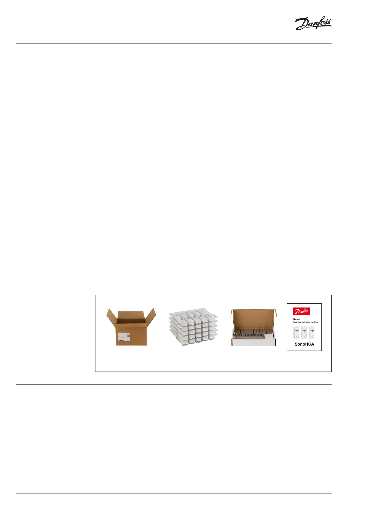
2.1 Packaging
2.2 General Description
Contents of the SonoHCA allocator box:
Box with label describing
the product
5 10-piece trays with
premounted lead seal
2.2.1 Type
The electronic heat cost allocators SonoHCA
operate either according to the single sensor
principle with start sensor or the double sensor
principle. The device has been developed and
approved in accordance with the European
Standard EN 83 4:2013.
2.2.2 Design
The heat cost allocator consists of a
microprocessor, a lithium battery, two
temperature sensors, a heat conducting
aluminium back plate, a multi-functional display
and a plastic housing.
1 box of 50 back plates Installation guide
The measuring circuit consists of the
temperature sensors, the analogue-digital
conversion, the reference resistance for
standardising the measuring transformation and
the microprocessor for accessing the radia-tor
heat output. During each measuring the circuit
tolerances are eliminated with a reference
resistance and the heat cost allocator carries out
an automatic self-test.
4 | VU.SH.H1.02 © Danfoss | 2019.03
Page 5
Operating Guide SonoHCA
2.2 General Description
(continuous)
Standard aluminium back plate for
nearly all existing bolts with common
dimensions and mounting possibilities
– thus easy installation
2.2.3 Characteristics
• Measuring by two temperature sensors,
radiator and ambient temperature sensor
(NTC-resistor).
• Optional measuring principle: 1 sensor mode
with start sensor or two sensor mode.
• Unit scale or product scale.
• Recording of cumulated heat consumption on
the annual set day.
• Recording of 144 monthly values and 18
half monthly values for cumulated heat
consumption.
• Recording of 18 monthly values for the
maximum radiator temperature.
• Optical interface for the readout of the data
and programming
• For heat cost allocator SonoHCA, the radio
module comprises a unidirectional radio
transmitter.
Two telegrams: short telegram, OMS
compliant and long telegram for Walk-by
reading.User-friendly operation by push
button.
• 6-digit and high-contrast LCD display.
• Automatic commissioning during the
mounting on the aluminium back plate
(available when ordering).
• Check code for postcard mail-in method
• Possibility to connect a remote sensor on each
version of heat cost allocator. The remote
sensor will be automatically detected by the
heat cost allocator.
• Remote sensor version with 2 m cable.
• Standard aluminium back plate for nearly
all existing bolts with common dimensions
and installation possibilities – thus easy
installation (no cutting and welding of bolts
necessary).
• Snap-on blind to cover colour shadows for
increased aesthetics.
• Safe operation and fraud/manipulation
detection.
• Lithium battery with a capacity of up to 10+1
year.
• Meets EN 834:2013.
Snap-on blind to cover
colour shadows for
increased aesthetics
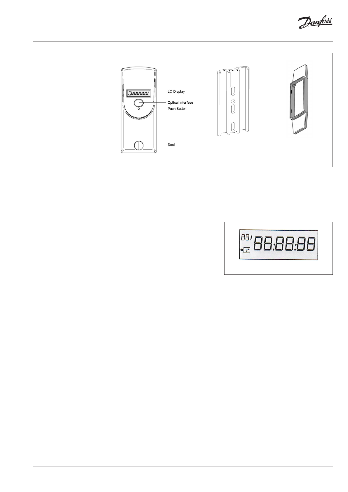
2.2.4 Display
The heat cost allocator has a LCD-display with 6
large main digits on the right and 2 smaller digits
on the left as well as two special symbols and
one communication indicator. The main digits
are separated by four decimal points. Below,
please find the display segments:
Display with all active segments
Normally, the heat cost allocators are supplied
with switched-off LCD-display. On request, the
heat cost allocators can also be supplied with
permanent LCD- display.
2.2.5 Electronics
The device has an electrical circuitry with
an 8-Bit-CMOS-micro controller of the latest
generation STM8L with extremely low current
consumption operating at a voltage as from
1.8 V.
The temperature measuring circuit with
automatic self-calibration measures the
discharging time of a capacitor. The accuracy
of the measuring circuit is independent of the
supply voltage.
2.2.6 Versions
For each version of heat cost allocator, it is
possible to plug the connector of the remote
sensor to an interface inside the heat cost
allocator.
Once equipped with a remote sensor, the heat
cost allocator will only work for an application
with remote sensor. Remote sensor version with
2 m cable.
VU.SH.H1.02 | 5© Danfoss | 2019.03
Page 6
Operating Guide SonoHCA
2.2 General Description
(continuous)
2.3 Technical data
2.2.7 Optical Interface
With a standardised optical probe the
consumption and configuration values can be
transferred directly to a computer. With the radio
heat cost allocator all consumption values can
be readout over the optical interface and over
radio. The data are transmitted in M-bus-format
acc. to EN13757-3. Authorised personnel can alter
the configuration of the device over the optical
interface with an optical probe.
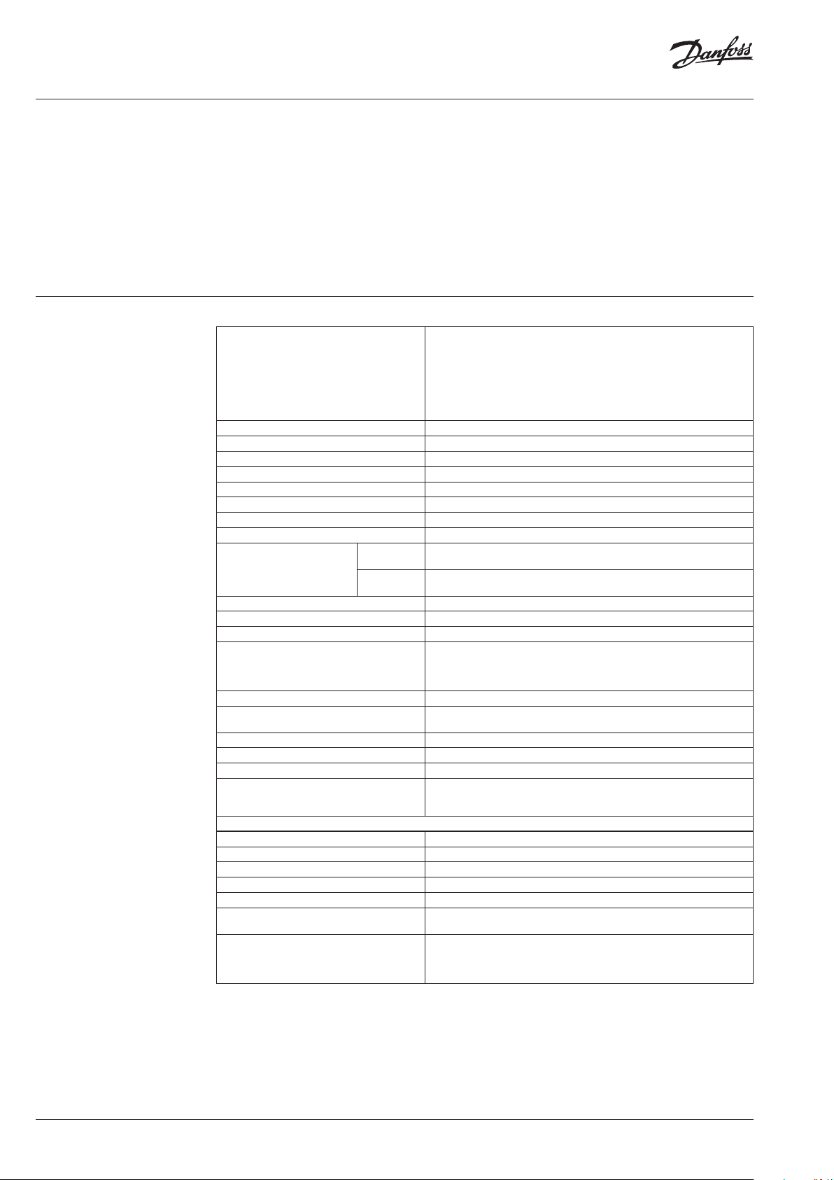
Single sensor device with start sensor
for heating systems with tmmin ≥ 55 °C
Calculation with set reference temperature 20 °C
Optional measuring systems:
Optional scales: Unit scale or product scale
Current supply: 3 V-Lithium-battery
Life-span with 1 battery: > 10 years
Display: Liquid crystal display (LCD-display)
No. of displayed digits: 6 digits (000000 ... 999999)
Sensor temperature range: 0 °C ... 120 °C
Exponent: n = 1.33
Radiator – performance range: 4 Watt ... 16.000 Watt
(tm
... tm
Design temperature range:
Values: Rating fac tors see digital KC-data base
Models: Compact device or remote sensor device
Set day: Freely programmable
Data storage:
Self-test: Before every measuring
Start of counting:
Satndard version: EN 834:2013
Homologation according to: HK VO : A1.0 2. 2015
Conformity: CE
Standard mounting height:
Wireless M-Bus radio communication
Frequency: 868.95 MHz
Communication: Unidirectional
Protocol: Wireless M-Bus
Encryption: AE S-128
Transmission standard: EN 13757-4, mode T1
Broadcasting interval:
Data transmission periods:
(tm
min
min
... tm
Necessar y rating factors: KQ, KC, (KA, KT)
Double sensor device
for heating systems with tmmin ≥ 35 °C
Calculation with variable ref. temperature T-air sensor
Necessar y rating factors: KQ, KC, (KA, KT)
Single sensor device with start sensor
)
max
55 °C ... 105°C / 120 °C (compact- / remote sensor)
Double sensor system
)
max
35 °C ... 105°C / 120 °C (compact- / remote sensor)
144 monthly values and 18 half monthly values for cumulated heat
consumption, 18 monthly values for the maximum radiator temperature.
Maximum temperature of the current and previous year, all relevant
consumption values
Heating period 25°C – 40°C (programmable)
Off-heating period 25°C – 40°C (programmable)
At 75% of the overall height of the radiator.
If the height of the radiator is less than (<) 470 mm, the heat cost allocator
must be installed at 50% BH.
Short telegram (OMS): > 120 s
Long telegram (walk-by): > 120 s
Short telegram (OMS): 24 h/d,
7 days a week
Long telegram (walk-by): < 12 h/d,
7 days a week
2.2.8 Radio Wireless M-Bus
The radio heat cost allocator features a
transmitter circuit in the 868 MHz band with
integrated antenna.
This radio module comprises a unidirectional
radio transmitter which is used to transfer data
according to the wM-Bus (EN 13757-4) radio
communication protocol and in compliance with
the OMS (Open Metering System) Release V3.0.1.
6 | VU.SH.H1.02 © Danfoss | 2019.03
Page 7
Operating Guide SonoHCA
2.3 Technical data
(continuous)
3. Settings
3.1 Settings
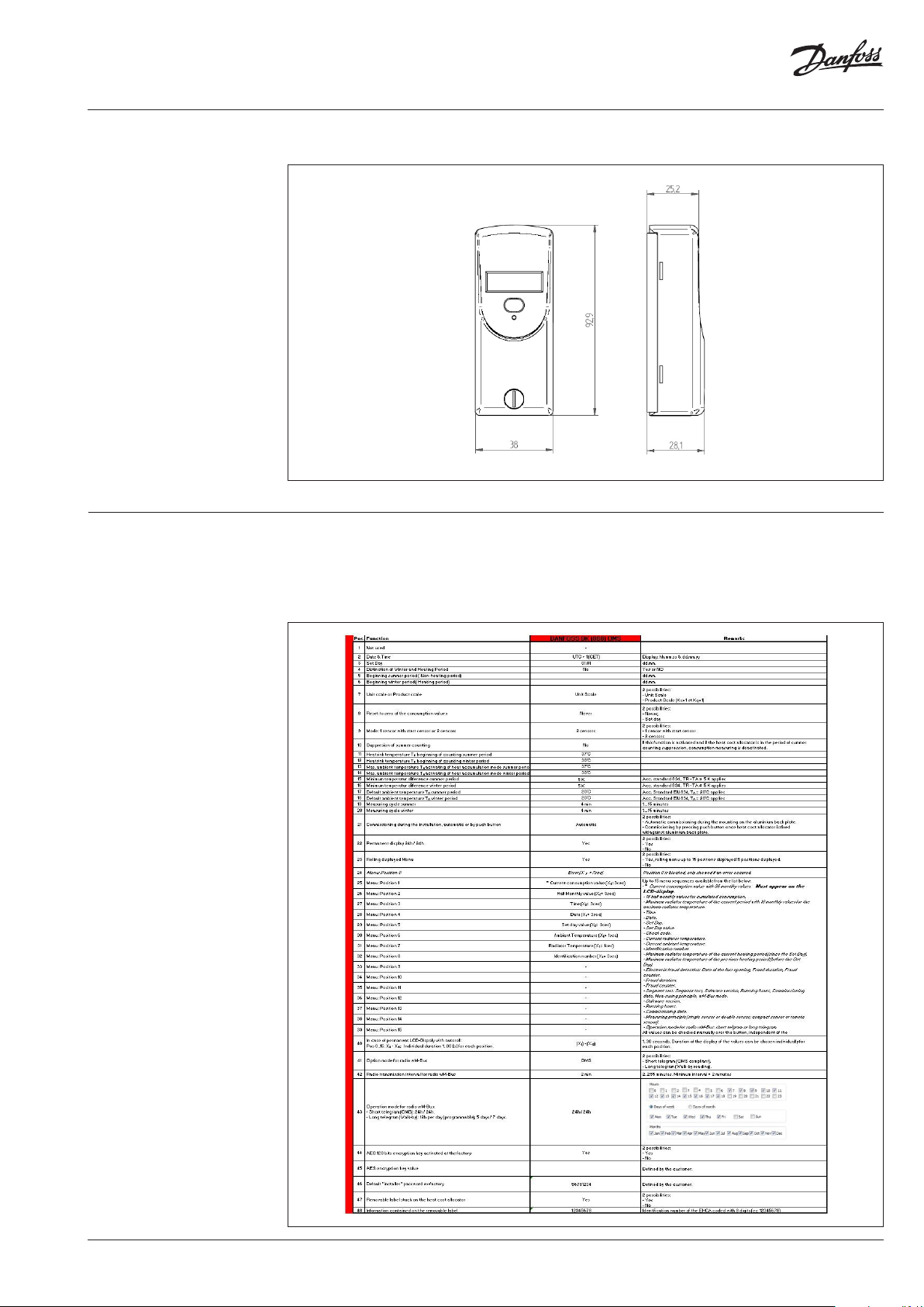
Dimension
The following table can be used to determine
the configuration of the heat cost allocator by
combining the different settings options that
follow.
Due to distinctive technical features, not
all possible combinations are necessarily
achievable.
Configuration sheet for SonoHCA:
VU.SH.H1.02 | 7© Danfoss | 2019.03
Page 8

Operating Guide SonoHCA
3.1 Settings (continuous)
• Position 1: Not used.
• Position 2: Allocator Date and Standard
Time:
The UTC time zone will be programmed
in accordance with the country where the
allocator is in-stalled.
• Position 3: Set Day (yearly date):
It is possible to program an annual set day on
which the cumulative consumption value to
date is recorded.
• Position 4: Setting Winter / Summer
Periods:
2 options: yes / no.
If the ‘yes’ option is chosen, two different
specific heating periods (winter and summer)
with different start temperatures settings
depending on the current period can be
distinguished.
• Position 5: Set the Start of the Summer
Period:
Choose the date on which the summer period
will begin.
• Position 6: Set the Start of the Winter
Period:
Choose the date on which the winter period
or the heating period will begin.
• Position 7: Unit Scale and Product Scale:
2 options: unit scale / product scale.
Set the type of scale used when calculating
the display values.
By default, the KC and KQ evaluation factors
will be set to 1 for the product scale.
• Position 8: Set Cumulative Values to Zero:
2 options: set day / never.
Determine whether the units’ consumption
totalizer will be reset to zero on the set day or
never.
• Position 9: Single Sensor or Dual Sensor
Mode:
Set the measuring method used by the
allocator.
2 options: single sensor / two sensors.
Single sensor: determines the amount of
heat emitted by a radiator by measuring and
assessing the radiator’s temperature with
respect to that of the room temperature
measured at the start and fixed at 20°C.
Two sensors: determines the amount of heat
emitted by a radiator based on the measured
temperature of the radiator via the radiator
temperature sensor and the ambient air
sensor.
• Position 10: Elimination of Summer
Counting:
2 options: yes / no.
If the ‘yes’ option is chosen, consumption will
not be measured during the summer period.
• Position 11: Radiator Temperature TR ,
Start Counting Summer Period:
Set the threshold temperature for the start
(counting) of the allocator. When this start
temperature is reached, the allocator will
begin to count the consumption units.
• Position 12: Radiator Temperature TR ,
Start Counting Winter Period:
Set the threshold temperature for the start
(counting) of the allocator. When this start
temperature is reached, the allocator will
begin to count the consumption units.
• Position 13: Max. room temperature TA ,
Activation of Heat Accumulation Mode,
Sum-mer Period:
Set a reference temperature in order to
avoid an incorrect measurement due to heat
accumulation (e.g. if the radiator is hidden by
panels, thermal accumulation). The allocator
will automatically switch into single-sensor
mode when the ambient temperature
measurement surpasses the defined reference
temperature. Following this, the calculation
will use an ambient temperature set to
20°C rather than the temperature actually
measured.
• Position 14: Max. room temperature TA ,
Activation of Heat Accumulation Mode,
Winter Period:
Set a reference temperature in order to
avoid an incorrect measurement due to heat
accumula-tion (e.g. if the radiator is hidden by
panels, thermal accumulation). The allocator
will automatically switch into single-sensor
mode when the ambient temperature
measurement surpasses the defined reference
temperature. Following this, the calculation
will use an ambient temperature set to
20°C rather than the temperature actually
measured.
• Position 15: Minimum Temperature
Difference, Summer Period:
Set a reference value calculated using the
temperature difference between the radiator
and the ambient air. According to the
standard EN 834: TR - TA ≤ 5 K.
• Position 16: Minimum Temperature
Difference, Summer Period:
Set a reference value calculated using the
temperature difference between the radiator
and the ambient air. According to the
standard EN 834: TR - TA ≤ 5 K.
• Position 17: Standard Ambient
Temperature TA, Summer Period:
Ambient temperature value used to calculate
the unit’s consumption. Set by the standard
EN 834: TA = 20°C.
• Position 18: Standard Ambient
Temperature TA, Winter Period:
Ambient temperature value used to calculate
the unit’s consumption. Set by the standard
EN 834: TA = 20°C.
• Position 19: Measuring Cycle, Summer
Period:
Set a time interval to be used as an operations
measuring cycle. The allocator will therefore
usually be in sleep mode.
• Position 20: Measuring Cycle, Winter
Period:
Set a time interval to be used as an operations
measuring cycle. The allocator will therefore
usually be in sleep mode.
• Position 21: Commissioning of the
Allocator:
2 options: Automatic commissioning upon
installation on the back plate / By pressing
the push button after installation on the back
plate.
The allocator leaves the factory in sleep mode,
meaning that it does not measure or calculate
consumption. The transition from sleep to
installation mode can be carried out in 2
8 | VU.SH.H1.02 © Danfoss | 2019.03
Page 9
Operating Guide SonoHCA
different ways: automatically upon installation
on the aluminium back plate or by pressing
the push button after having installed it on
the aluminium back plate.
• Position 22: 24-hour Active Display:
2 options: yes / no.
If the ‘no’ option is chosen, the display will
always be switched off. By pressing the push
button, the LCD screen will become active.
After 3 minutes of inactivity, the screen will
automatically re-turn to deactivated mode.
If the ‘yes’ option is chosen, the display will be
active 24 hours a day.
• Position 23: Scrolling Display Menu:
2 options: yes / no.
If the ‘no’ option is chosen (static display), the
menu can be changed by pressing the push
button.
If the ‘yes’ option is chosen, the display will
automatically move from one menu to the
next. The display duration can be configured
individually for each duration.
• Position 24: Error Information Display:
If an error occurs, the Err message will appear
on the LCD screen. This information will
appear at the top of the menu sequence.
• Positions 25 to 39: 15 values which can be
displayed.
• Position 40: Programmable Display Time
for Each Value Shown.
• Position 41: Operation Mode for the
Wireless M-Bus Radio:
2 options: short telegram (OMS) / long
telegram (Walk-by).
• Position 42: Transmission Interval for
Wireless M-Bus Radio Telegram:
Set a transmission interval for sending
Wireless M-Bus radio telegrams.
• Position 43: Wireless M-Bus Radio
Telegram Transmission Period.
Short telegram (OMS): 24 hours a day, 7 days a
week.
Long telegram (walk-by): 12 hours chosen per
day (programmable), 7 days a week.
• Position 44: AES-128 Encryption Activated
at Factory:
2 options: yes / no.
If the ‘yes’ option is chosen, the encryption
key can be programmed according at the
customer’s request.
• Position 45: Decryption Key:
Contact the local Danfoss for Decryption Key.
• Position 46: Installer Password:
Default password: 56781234
This may be chosen by the customer.
• Position 47: Detachable Label Attached to
the Heat Cost Allocator:
2 options: yes / no.
If the ‘yes’ option is chosen, a detachable
label will be attached to the front face of the
allocator.
• Position 48: Information Contained on the
Detachable Label:
The information contained on the detachable
label may be chosen by the client.
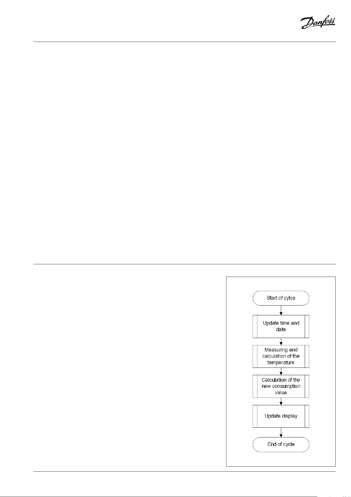
3.2 Operating mode 3.2.1 Cycle
The heat cost allocators SonoHCA operate in a
cycle of 4 minutes. Most of the time, the device is
in sleeping mode. Every 4 minutes the device is
set into operation and operates according to the
adjoining diagram.
The clock-pulse generator is a counter which is
completely independent from the rest of the
program. This counter is designed in a way so
that it is impossible to stall the cycle or to skip
one or more cycles.
Each cycle follows the adjoining diagram.
The measuring and calculating processes are
explained in detail later.
The tasks carried out during one cycle are taking
approx. 100 ms. This means that the device is in
sleeping mode more than 99.8 % of the time. It
can be set into operation between two cycles
over the optical probe or by pushing the button.
In this case it carries out the requested task and
then returns to sleeping mode.
In case an optical probe is connected or the
button is pushed during the course of the cycle,
the respective value is readout at the end of the
cycle.
The button can be pushed for an indefinite
period of time and the optical probe can be
left in its position since the normal function of
the device is not impaired by an influence from
outside.
VU.SH.H1.02 | 9© Danfoss | 2019.03
Page 10

Operating Guide SonoHCA
3.2 Operating mode
(continuous)
3.2.2 Single Sensor Version with Start Sensor
The start sensor of the single sensor version
serves as an ambient temperature sensor which
mainly functions during the heating up period.
The start temperature is the threshold
temperature of the radiator at which the device
always starts to carry out energy ratings. For
these ratings, the measured radiator temperature
and an assumed ambient temperature of 20° C
are used as calculation basis.
3.2.3 Dual Sensor Version
For the dual sensor version basically the
same specifications apply as for the single
sensor version with start sensor. However,
for calculating the room temperature the
real temperature, measured by the ambient
temperature sensor (corrected via the
corresponding radiator-dependent „Kairvalue“),
is used as the basis.
3.2.3.1 Heat Accumulation Mode
In order to avoid faulty measuring due to heat
accumulation (e.g. in case the radiator is hidden
by panels), the device switches from a defined
ambient temperature (e.g. 28°C) to the one
sensor mode and calculates with an ambient
temperature of 20° C.
3.2.4 Comparison of the Measuring
Principles
Single sensor device with start sensor
measuring principle
For heating systems with tm
≥ 55 °C
min
The heat cost allocator calculates with a set
reference temperature of 20 °C
Application:
Single sensor devices with start sensor are used
in areas where normal ambient temperatures are
given. For low temperature heating systems the
double sensor device is recommended.
For radiators which are covered or blocked by
fix-tures, normally the single sensor devices are
used because the double sensor device is not
in a posi-tion to capture the current ambient
temperature due to the heat accumulation.
double sensor system which then switches over
internally to the single sensor mode.
Within one billing unit, only one measuring principle
(either single sensor measuring principle with start sensor
or double sensor measuring principle) can be used. Mixed
fitments or the use of different types of devices in the
same billing unit is therefore also not allowed.
The processes for determining the K-value for
the single sensor device with start sensor and the
double sensor device are identical. It is only the
measuring principle that is different.
3.2.5 Temperature Measurement and
Calculation
The temperature is measured with an NTC –
resistor. For the resistance measurement the
discharging time of the capacitor is measured.
The measurement is carried out as follows:
3.2.5.1 Measuring of a Resistor, Principle
1. Charging of the capacitor
2. Discharging of the capacitor through the
resistance which is to be measured. At the
same time a 16+1 bit-timer starts with the
discharge to measure the discharging time
3. As soon as the voltage on the capacitor
terminals reaches a certain value, an interrupt
is induced and the timer stops. At the same
time the discharging of the capacitor is
stopped as well.
After the three mentioned stages, the timer
provides a 16-bit-value which corresponds to the
discharging time of the capacitor through the
resistance which is to be measured. In case the
resistance is known (reference resistance), the
constant ratio between discharging time and
resistance can be assessed.
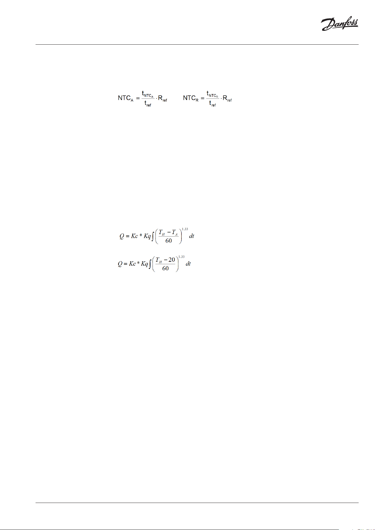
3.2.5.2 Calculation of the Value of an
Unknown Resistance (e.g. sensor
resistance)
The capacitor C is loaded at constant current. The
interrupt at the end of the discharge is triggered
by the same threshold voltage (a fraction of the
discharge voltage). If these two conditions are
met, the discharge time is directly proportional
to the resistance. With a reference resistance R
whose exact value is known, it is now possible to
ref
calculate the unknown resistance value Rx with
the following equation:
Double sensor measuring principle
For heating systems with tm
≥ 35 °C
min
The heat cost allocator calculates with a variable
reference temperature T
air temperature
Application:
Double sensor devices are used in areas where
precise measuring of the ambient temperature
is necessary and/or in low temperature heating
systems.
Radiators which are covered or blocked by
fix-tures are detected automatically by the
From this equation the self-calibration of the
converter can be derived, which is given by
measuring the discharging time through the
reference resistance.
3.2.5.3 Measuring of the Radiator and
Ambient Temperature
The following measurements are carried out
during one cycle:
1. Measuring of the reference resistance Rref
2. Measuring of the ambient temperature sensor
NTC
A
10 | VU.SH.H1.02 © Danfoss | 2019.03
Page 11
Operating Guide SonoHCA
3.2 Operating mode
(continuous)
3. Measuring of the radiator temperature sensor
NTC
R
The measuring values are calculated with the
following formula:
The reference resistance value is defined ex
works with a tolerance of 0.5% with 50 ppm.
The reference resistance features an excellent
temperature and long-term stability.
The capacitor value and the threshold voltage
have to remain stable over the whole cycle.
However, they can vary at the medium- or long
term without causing any failures because the
self-calibration of the converter is repeated
in every cycle while measuring the reference
resistance.
3.2.6 Calculation of the Displayed
Consumption Value
The value displayed on the heat cost allocator is
calculated as follows:
Single sensor device
Double sensor device
3.2.7 Start of Counting
The updating (increment) of the consumption
value is carried out under the following
conditions:
During winter period (heating period):
(TR ≥ 25 °C)
or
(TR ≥ 20 °C) AND (TR - TA ≥ ΔT
MIN
)
During summer period (off heating period):
(TR ≥ 35 °C)
or
(TR ≥ 20 °C) AND (TR - TA ≥ ΔT
MIN
)
Explanation:
TR Radiator temperature
TA Ambient temperature
ΔT
Minimum temperature difference between
MIN
radiator and room
3K for standard device (winter heating
period standard setting)
4K for remote sensor device (summer
heating period standard setting)
Note:
The thresholds of starting (25°C et 35°C) are indicative
values. These temperatures of starting are adjusted
according to the needs and specif icities of the customer.
Explanation:
TH Temperature of the radiator surface in [°C]
TA Ambient temperature in [°C]
Q Displayed consumption value, without
unit
Kc Factor that carries back the ΔT measured at
a normalized value
Kq Factor Kq is a numerical value of the
nominal power of the radiator stated in
[KW]
Unit scale:
Kc = 1 and Kq = 1
Product scale:
Kc <> 1 and Kq <> 1
VU.SH.H1.02 | 11© Danfoss | 2019.03
Page 12
Operating Guide SonoHCA
3.3 Display and
Additional Functions
3.3.1 The Menu Sequences of the Digital
Display
The menu sequences
Ex-factory all menu sequences are activated.
With a software the order of the menu sequences
1 - 15 can be changed in any order. However the
order within the individual menu sequences 1 –
15 cannot be changed. It is also possible to hide
individual menu sequences so that they are not
visible to the end-user.
When reading out over the optical interface
or via radio the complete set of data is always
readout and transferred.
Operation of the Push Button
When pushing the button briefly the digital
display always goes to the next menu sequence.
When pushing the button in one menu sequence
for 2 seconds the individual values within the
selected menu sequence can be accessed. When
the last value within one menu sequence has
been displayed, the 1st position will be displayed
by pushing the button again.
If the button is not pushed for 2 minutes,
the digital display returns to the cumulated
consumption value.
3.3.2 The Digital Display
During normal operation the display is
deactivated and can be activated by pushing the
button.
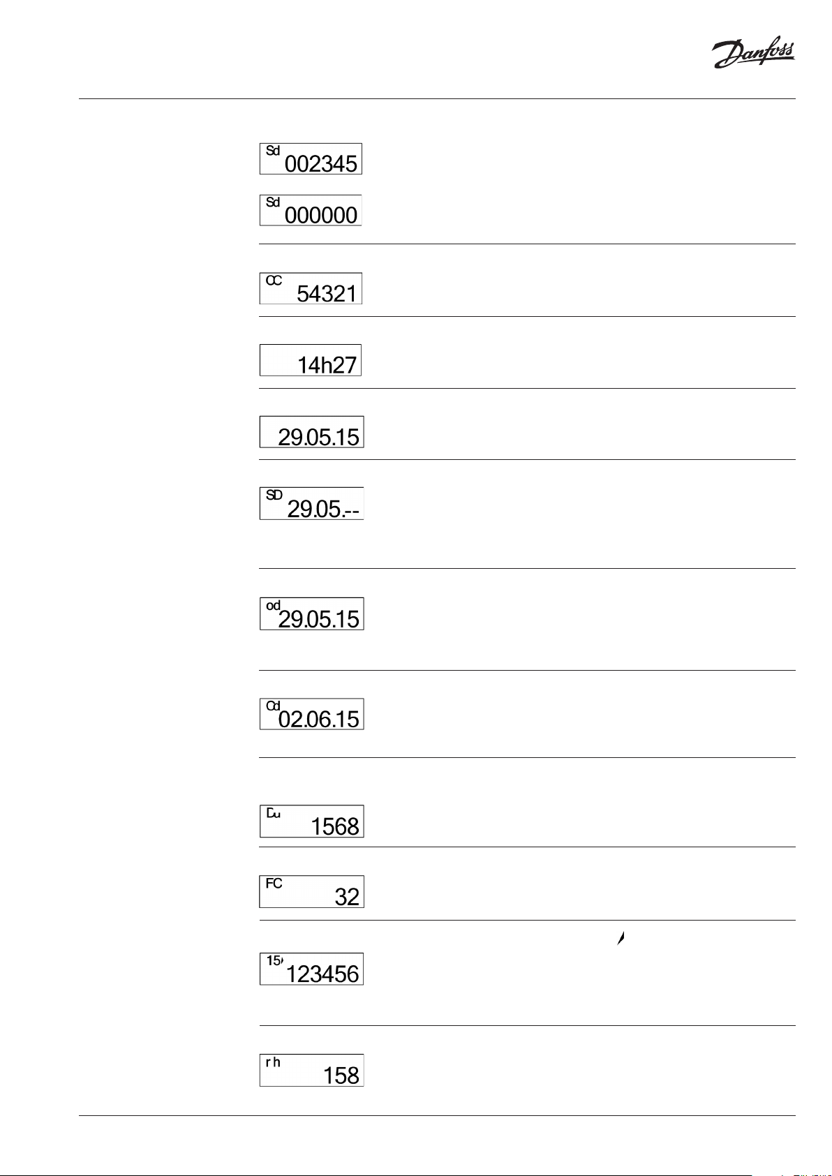
Consumption Value Unit Scale
Consumption Value Product Scale
Indicazione in EURO
If the button is not pushed, the display will be
active for 2 minutes only.
On request, the heat cost allocator is also
available with permanent display 24h/24h or
with a rolling menu displayed.
On the display of the heat cost allocator with
unit scale an index u for unit is shown on the left
side. If the index u is not displayed, the heat cost
allocator is equipped with the product scale.
When commissioning the device this value is
000000. When reaching the value 999999, the
counting restarts automatically at 000000.
The heat cost allocators have the option to
display the heating cost in Euro.
The cost in Euro indicated on the display is only
approximate and is based on historical values
from the previous year.
The displayed cost does not necessarily
represent the charges to be paid.
Manufacturer and supplier decline any claims
concerning the use and interpretation of the
indicated values.
This option can be activated via a software.
12 | VU.SH.H1.02 © Danfoss | 2019.03
Page 13
Operating Guide SonoHCA
3.3 Display and
Additional Functions
3.3.2 The Digital Display
(continuous)
Set day Value
Check code
Time
Date
Set Day
With the index Sd the consumption value
recorded at midnight of the set day is displayed.
The consumption value recorded can be in unit
scale or in product scale. It’s depending of the
unit setting.
If a new device has not yet reached the
programmed set day, 000000 is displayed.
With the index CC the check code for the
plausibility check of the manual readout is
displayed.
The current time (always winter time).
The current date of the heat cost allocator.
It is possible to program an annual set day on
which the cumulated consumption value as
well as the maximal radiator temperature are
recorded.
With the index Sd the programmed annual set
day is displayed.
Date of Opening of the Device
Commissioning Date
Cumulated Duration of the Opening of the
Device
Fraud Counter This value indicates how many times the fraud /
Identification Number
Each heat cost allocator is equipped with a
manipulation protection which detects an
unauthorised opening of the device after
installation to the radiator. The date of the last
opening of the device is recorded and displayed
with the index od.
With the index Cd the commissioning date is
displayed, i.e. the date on which the device has
been activated by pushing the button or during
the mounting of the aluminium back plate if the
function automatic commissioning is set.
With the index du, the cumulated duration in
minutes during which the device was opened
is detected. This display turns up only after
commissioning in case the heat cost allocator
was opened or removed.
manipulation was activated.
With the index an 8 digit identification number
is displayed. Ex-factory the serial number is
identical with the identification number. The
first two digits of the identification number are
the two small digits on the left upper side of the
digital display.
Running Hours With the index rh, the running hours is displayed.
This value can be compared to the battery use
duration.
VU.SH.H1.02 | 13© Danfoss | 2019.03
Page 14
Operating Guide SonoHCA
3.3 Display and
Additional Functions
3.3.2 The Digital Display
(continuous)
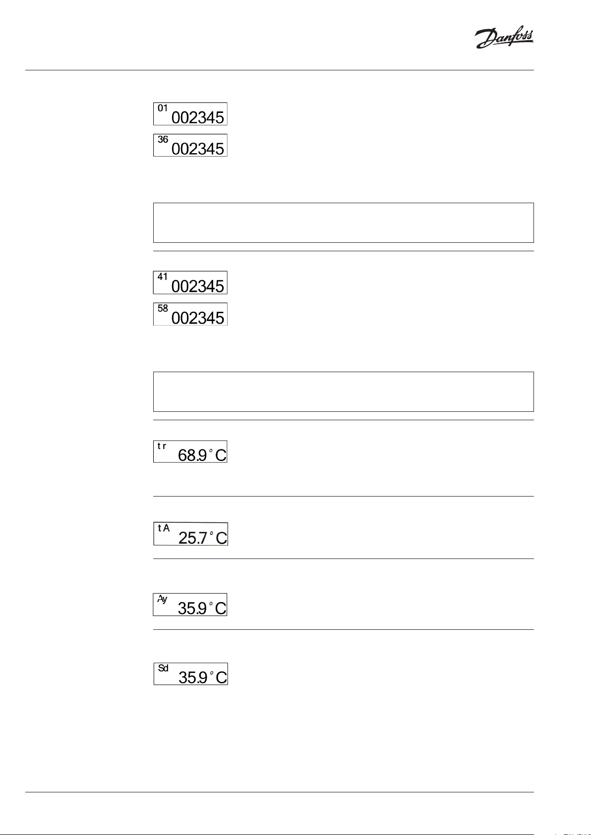
Monthly Values The cumulated consumption values are recorded
automatically at midnight on the last day of each
month.
Number of monthly values: 36
The small digits on the upper left side show
the number of previous monthly values. Digit
01 stands for the recent full month and digit 36
stands for the least recent month. All monthly
values are set to 000000 when the device is
commissioned.
Note :
Short telegram, OMS compliant: no monthly values transmitted via radio telegram.
Long telegram for Walk-by reading, the first 18 monthly values transmitted via radio telegram.
Half Monthly Values The cumulated consumption values are recorded
automatically at midnight on the 16th of each
month.
Number of monthly values: 18
The small digits on the upper left side indicate
the number of half monthly values. Digit 41
stands for the recent half monthly value and digit
58 for the least recent half monthly value. All
half monthly values are set to 000000 when the
device is commissioned.
Note :
Short telegram, OMS compliant and long telegram for Walk-by reading: no half monthly values transmitted
via radio telegram.
Radiator Temperature
Ambiant Temperature
Maximum Radiator Temperature of the
Current Heating Period
Maximum Radiator Temperature of the
Previous Heating Period
With the index tr the current radiator
temperature is displayed.
With the index tA the current ambient
temperature is displayed.
With the index ΠΨ the maximum radiator
temperature of the current heating period (since
the Set Day) is displayed.
With the index Sd the maximum radiator
temperature of the previous heating period
(before the Set Day) is displayed.
14 | VU.SH.H1.02 © Danfoss | 2019.03
Page 15

Operating Guide SonoHCA
3.3 Display and
Additional Functions
3.3.2 The Digital Display
(continuous)
Monthly Value for Maximum Radia-tor
Temperature
Software Version
Measuring Principle
Segment Test
With the index ΠΠ the maximum radiator
temperature of the currently month is displayed.
Number of monthly values: 18
Recording of 18 monthly values for the maximum
radiator temperature.
The small digits on the upper left side show
the number of previous monthly values. Digit
01 stands for the recent full month and digit 18
stands for the least recent month.
All monthly values are set to 000000 when the
device is commissioned.
On the right side the software version x.x.x of the
heat cost allocator is displayed.
The index -- or FF indicates the type of the
radiator sensor:
-- = Standard device, compact sensor.
FF = Remote sensor device, remote sensor.
1 SENS = single sensor device with start sensor.
2 SENS = double sensor device.
Segment test of the display.
Error Message
wM-Bus mode
3.3.3 Rolling Display
The SonoHCA also feature the possibility of a
rolling display 24h/24h.
With a software it is possible to individualize the
rolling display.
Up to 15 parameters can be chosen optionally
from the list below. These parameters can be
combined in any order and are then shown on
the rolling display.
• Consumption value.
• Time.
• Date.
• Set Day.
• Set Day value.
• Monthly values.
• Half monthly values.
• Radiator temperature.
• Ambient temperature.
• Identification number.
If an error is detected, Err is displayed in the first
display sequence with the corresponding error
message.
Telegram defined into heat cost allocator.
Type of telegram must be defined when
ordering.
Short telegram (Short ) used.
Long telegram (LonG) used.
• Maximum radiator temperature of the
previous heating period.
• Maximum radiator temperature of the current
heating period.
• 18 monthly values for the maximum radiator
temperature.
• Error code.
• Manipulation protection: storing of the
duration of the last manipulation with
date and the accumulated duration of all
manipulations in minutes.
• Fraud Counter.
• Segment test.
• Software version.
• Running hours.
• Commissioning date.
• Measuring principle, single sensor device with
start sensor or double sensor device.
• Short or long telegram for radio wM-Bus.
The duration of the display of the values can be
chosen individually between 1 - 30 seconds.
VU.SH.H1.02 | 15© Danfoss | 2019.03
Page 16

Operating Guide SonoHCA
3.3 Display and
Additional Functions
3.3.3 Rolling Display
(continuous)
Example:
Order and duration of display
• Pos 0: Error [5 s]
(parameter ex factory, cannot be changed)
(only displayed in case of an error message)
• Pos 1: Time [1 s]
• Pos 2: Segment test [5 s]
• Pos 3: Consumption value [10 s]
• Pos 4: Set Day [1 s]
• Pos 5: Set Day value [8 s]
• Pos 6: Monthly value [5 s]
• Pos 7: Blank (therefore no display).
• Pos 8 – Pos 15: Blank (therefore no display. It
is not necessary to occupy all positions).
3.3.4 Communication Indicator and
Measuring Indicator •
The communication indicator displays if the heat
cost allocator is currently making a calculation
and/or if it communicates internally or externally
over the optical or wireless interface.
The rolling display can also be deactivated by a
software, i.e. the device operates as in standard
menu mode except that only these values and
the values of the corresponding sub-menus that
have been de-fined in the rolling menu can be
displayed by pushing the button. After 2 minutes
during which the button has not been pushed,
the display goes out.
If the arrow of the communication indicator
points inwardly internal communication takes
place over the optical or wireless interface.
If the arrow of the communication indicator
points outwards external communication takes
place over the optical or wireless interface.
If the frame of the communication indicator
appears the heat cost allocator has detected a
wake-up signal.
If the point indicator appears the heat cost
allocator is carrying out a measuring or a
calculation.
3.3.5 Real Time Clock and Calendar
The device has a 24 h real time clock and a
calendar. However, the change from summer
to winter time is not taken into account. The
calendar is programmed until December 31
If the current date and time have to be updated over the optical interface or via radio, it is necessary to check the
date of the computer first. Date and time of the device aim at those of the computer. If the reading/programming
device (computer/PDA/ Smart Phone) has a wrong time, this time will be programmed into the heat cost allocator
and suddenly no longer be reached at the usual time, because the time of the heat cost allocator possibly is shifted
by several hours.
Important: The time on your readout / programming interface must always be set to winter time
3.3.6 Check code
A special additional feature of the electronic heat
cost allocator is the check code function for the
post-card mail-in method.
With especially developed algorithms a 5 digit
check code is generated out of several device
data. With this check code the values stated on
the postcards mailed-in by tenants can be cross
checked.
2099, including all leap years. The real time clock
as well as the date of the heat cost allocator can
be readout over the optical interface or via radio
and if necessary be updated.
For this check, the following parameters are
required:
• Identification number.
• The date.
• The current consumption value.
• The check code.
For the verification of the check code Danfoss
places all necessary tools (programs, formulas) at
the disposal of the authorized personnel.
16 | VU.SH.H1.02 © Danfoss | 2019.03
Page 17

Operating Guide SonoHCA
3.4 Special Functions
3.4.1 Suppression of Summer Counting
The period during which summer counting is
suppressed can be programmed by the software.
If the heat cost allocator is in the period of
summer counting suppression, consumption
measuring is de-activated. If an automatic
readout is carried out during this period the
temperatures can be read anyway since the
temperature measuring is still active.
3.4.2 Annual Reset of the Consumption Value
The function of the annual reset of the
cumulated consumption value can be
programmed by the soft-ware over the optical
interface. One of the following options can be
chosen for the reset:
• Set Day
• Never
Please note that only the cumulated
consumption value is reset. All other values are
not reset.
3.4.3 Unit Scale and Product Scale
For the heat cost allocators, distinction is made
between the unit scale and the product scale.
See chapter 7.2 Table of Rating Factors.
3.4.3.1 Advantages of the Unit Scale
If heat cost allocators are used with the same
scale on all radiators, this scale is called unit
scale. The display values are the same on the
different radiators if the heat cost allocators are
exposed to the same temperature for the same
period of time.
The evaluation of the display values is carried
out arithmetically with the rating factors of
the calculation software to receive the final
consumption values.
• Easy and quick installation of the heat cost
allocator, no programming necessary.
• Possible errors by doing the scaling on site are
avoided due to allocation by experts.
3.4.3.2 Advantages of the Product Scale
With the product scale, the radiator rating data
are programmed in the heat cost allocator on
site. The overall rating factor K is calculated
directly in the heat cost allocator and thus the
consumption value is displayed immediately.
• The actual consumption of each consuming
point within one billing unit can be compared
easily and quickly on site.
3.5 Parameterization
3.6 Error
A software allows the parameterization over the
optical interface.
To protect heat cost allocator against fraud, a
password has been integrated into the products,
therefore also in the software. The default
‘’installer’’ password ex-factory of the heat cost
allocator is ‘’56781234’’, and may be changed by
the user.
The heat cost allocator displays an error message
with the 3 letters “ Err. ” and a code. If several
errors occur at the same time, the different codes
are added together.
The error is displayed in the first position of the
display menu. It will still be possible to select
all the other display menus by pressing the
navigation button. If the navigation button is
no longer pressed for a period of 2 minutes, the
error code will automatically appear again in the
first position of a display menu.
Display of an error automatically disappears
when the error is no longer present.
3.6.1 List of Errors
• Err. 1 Manipulation (fraud).
• Err. 2 Measuring error.
• Err. 32 Push button constantly pushed.
• Err. 64 Measured temperature not within
temperature range (0...105°C ;
0...120°C remote sensor).
VU.SH.H1.02 | 17© Danfoss | 2019.03
Page 18

Operating Guide SonoHCA
4. Installation
4.1 Introduction
4.2 DIN Standard
Requirements for the
Installation
To guarantee the proper functioning of the heat
cost allocator SonoHCA, it is of great importance
that it is installed by an expert. On one hand, a
constant heat transfer between radiator and heat
cost allocator has to be guaranteed. On the other
hand, the installation of the heat cost allocators
on a large variety of radiator types should be as
easy as possible.
The installation can be carried out in two
different ways.
• The standard device is installed directly on
the radiator.
• For the wall-mounted version the remote
sensor is installed on the radiator and the heat
cost al-locator is wall-mounted.
• Heat cost allocators can be installed in
heating systems where the mean temperature
is between the upper operating temperature
limit t
limit t
technical data, see chapter 2.3 Technical data).
and the lower operating temperature
max
(t
min
max
and t
are stated in the
min
• The installation of the devices has to be
durable and avoid manipulations.
• The devices have to be installed in a place
where sufficient correlation between the
displayed value and the heat output of the
radiator is given over a maximum operating
range.
• Within a billing unit (in case of predistribution of the energy consumption:
within a users’ group) only heat cost allocators
of the same manufacturer and the same type
with identical rating systems may be used.
Each device type has to be identifiable as
such.
For the installation of the heat cost allocators,
special fastening-parts kits are available. To
avoid faulty installation, we also recommend
reading the Kc-data in the data base prior to the
installation.
(See chapter 7.2 Table of Rating Factors).
The heat cost allocator is an electronic device
which – like all other similar devices – has to
be handled with care. It is sensible to electric
discharge and contacting certain areas of the
PCB. Electric discharge can destroy the device
or – even worse - damage it in a way that it fails
after an indefinite period of time.
For this reason it is essential in any case to
avoid contact with the PCB.
• Combinations of radiators and heat cost
allocators with a measured value of c >
0.3 in basic condi-tion are not permitted.
In exceptional cases c-values of up to 0.4
are permitted within a billing unit if the
concerned heating surface does not exceed
25 % of the overall heated surface or if the
mean ambient temperature is above 80°C.
Heat cost allocators may only be installed to
radiators where the c-value is known at the
time of billing.
4.3 General Restrictions
Electronic heat cost allocators cannot be used
with steam heating, floor heating, ceiling radiant
heaters, flap-controlled radiators and electrical
radiator.
In case of combined valve- and flap-controlled
radiators, the installation of an electronic heat
Convector heaters where the performance can
be altered by an electric blower as well as heat
towel racks with an electric heating cartridge
may only be equipped with an electronic
heat cost allocator if the additional electric
attachments are dismounted or shut down.
cost allocator is only permitted if the flap control
is dismounted or maintained in position „open“.
4.4 Operating Range
SonoHCA can be used in heating systems
with the following mean heating medium
temperatures:
For single sensor devices with start sensor
A heat cost allocator can be used in heating
systems where the suitability of the system is in
line with the operating conditions for which the
heat cost allocator has been approved.
• 55°C…105° C for standard heat cost allocator.
• 55°C…120°C for wall-mounted heat cost
allocator (remote sensor).
For double sensor devices
• 35°C…105° C for standard heat cost allocators.
• 55°C…120°C for wall-mounted heat cost
allocators (remote sensor).
18 | VU.SH.H1.02 © Danfoss | 2019.03
Page 19
Operating Guide SonoHCA
4.5 Allocator Installation
Position – Standard
Installation
The installation position on the radiator is
directly related to the type of radiator, its heating
power and the heat cost allocator. To guarantee
the correct data collection, the heat cost
allocators must be installed and used in a certain
position in accordance with requirements
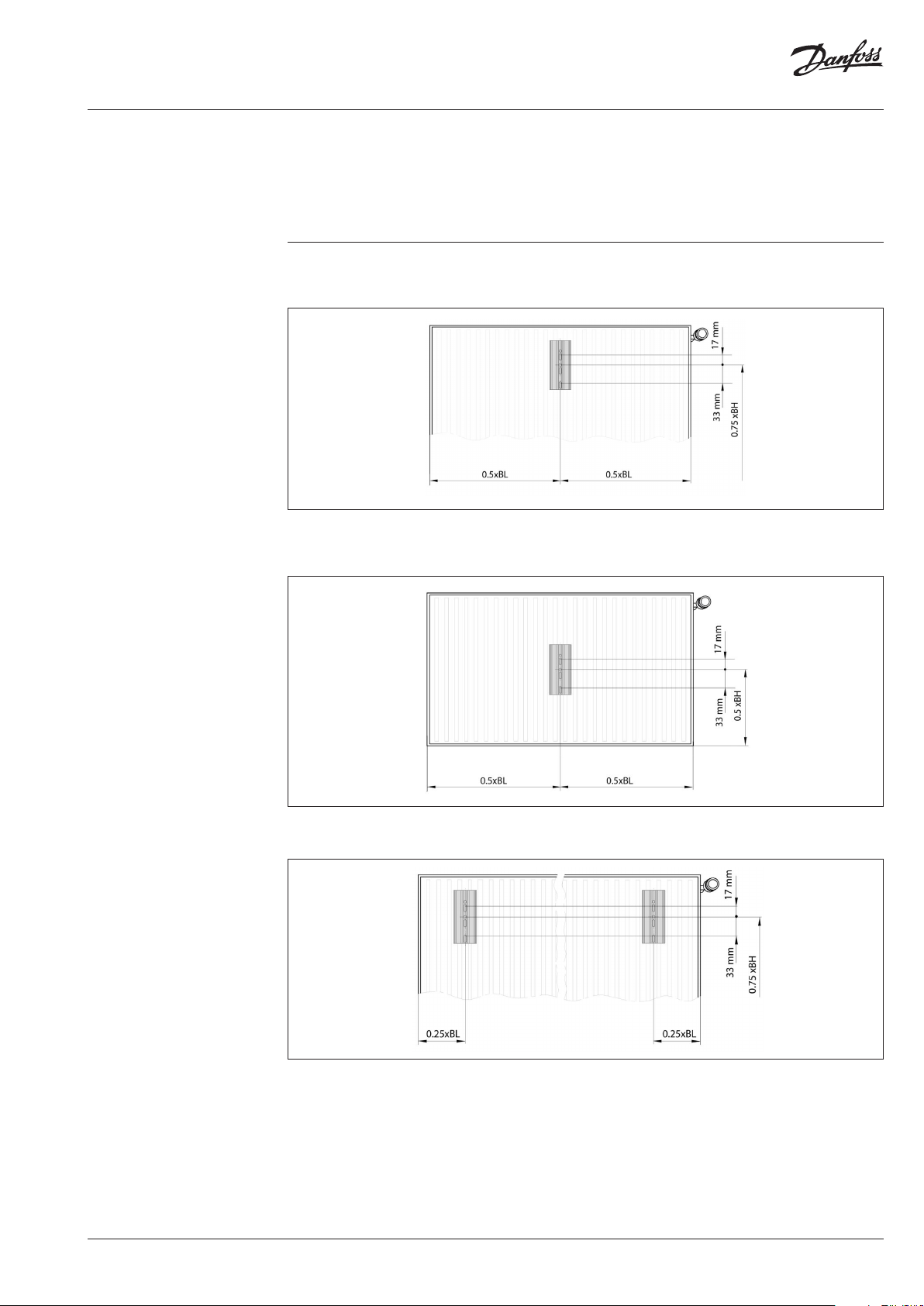
• The SonoHCA heat cost allocator is always
installed in the centre of the overall length
(0.5 x BL) of the radiator, at a height of ¾ of
• If the height of the radiator is less than (<) 470
mm, the heat cost allocator must be installed
at 50% BH.
The radiator’s heat is transmitted directly
via the installation back plate to the device’s
temperature sensor or to its remote sensor
the overall height (0.75 x BH) measured from
the bottom.
• If the radiator has a length of more than 3 m,
two heat cost allocators must be installed.
General notes:
• The spacing for welding the M3 threaded
bolts must be 5 cm. Before welding, the
lacquer has to be removed from the welding
points. It must be ensured that the bolts are
welded onto a water-bearing area or a flute.
• Only use M3 bolts with a maximum length
of 8 mm or there is a risk that the device will
be damaged.
These radiators are considered to be 2
radiators arranged next to each other.
• Welding to aluminium radiators is not
permitted.
• If the radiator has an even number of sections
the heat cost allocator should be installed
between the middle sections.
• If the radiator has an uneven number of
sections the device should be installed next
to the valve-sided middle section.
• Mount the back plate through the 2 oval
holes, adjusted to the top edge of the holes.
VU.SH.H1.02 | 19© Danfoss | 2019.03
Page 20

Operating Guide SonoHCA
4.6 Mounting the Remote
Sensor
For each version of heat cost allocator, it is
possible to plug the connector of the remote
sensor into an interface inside the heat cost
allocator.
The remote sensor will be automatically
detected by the heat cost allocator.
Return the heat cost allocator and plug the connector of the
remote sensor into the interface inside the heat cost allocator.
Proceed to the commissioning of the heat cost
allocator on the aluminium back plate. Take care
not to stick the cable.
Remark concerning the recognition of the
remote sensor:
Once heat cost allocator is fixed with/against the
aluminium back plate, the LCD-display will show
the following message during few seconds:
Once equipped with a remote sensor, the
heat cost allocator will only work for an
application with re-mote sensor.
Remote sensor version with 2 m cable. The cable
includes a stopper-knot.
Stopper-knot
Insert the remote sensor cable into the
groove provided up to the slot of housing.
Place the stopper-knot inside the housing.
The knot will avoid any traction on the
con nect or.
Once heat cost allocator has recognized the
remote sensor, push the seal pre-installed by
Danfoss in the slot of the housing. Then press
until the seal clicks into the aluminium back
plate.
Respect the color code of the radiator sensor
and the remote sensor. For Heat cost allocator
SonoHCA the radiator sensor and the remote
sensor are manufactured in two colors white and
yellow.
Once equipped with a remote sensor, the heat
cost allocator will only work for an application
with remote sensor.
• The index FF indicates that the heat cost
allocator has recognized the remote sensor.
• If the remote sensor is not detected by the
device, the index -- will be displayed. The
index -- indicates also a standard device with
a compact sensor. If the remote sensor is not
recognized, check the plug connector in the
heat cost allocator.
If the remote sensor is disconnected from the
heat cost allocator, an error message will be
displayed.
During the commissioning of the heat cost
allocator on the aluminium back plate, there are
2 possibilities to turn on the heat cost allocator:
1. By an automatic commissioning during the
mounting on the aluminium back plate.
See chapter 5.1 Automatic commissioning
during the installation
By pushing the push button. See chapter
Commisoning by pressing push button.
20 | VU.SH.H1.02 © Danfoss | 2019.03
Page 21

Operating Guide SonoHCA
4.7 Wall Mounting
The heat cost allocator has to be wall-mounted if
the overall height of the radiator is less than 250
mm or if, for aesthetical reasons, the heat cost
allocator cannot be mounted directly onto the
radiator.
In this case, the heat cost allocator is wallmounted on the side opposite to the valve and at
a minimum distance from the radiator of 10 cm.
088H2424
088H2425
088H2420
• After marking and drilling the holes, the
aluminium profile is fastened with 2 metal
screws and 2 spring washer.
• The parts necessary for the wall-mounting are
included in the corresponding fastening-parts
kits for the installation of the remote sensor.
• After installation of the device to the wall and
the sensor to the radiator, the sensor cable is
laid in a cable duct.
088H2423
• Mount the back plate through the 2 oval holes
adjusted to the top edge of the 2 oval holes.
Mounting Accessories Part . No.
2 plastic dowels Ø5 mm 3.25 088H2424
1 aluminium back plate (supplied with
SonoHCA)
2 spring washers 088H2420
2 oval head wood screws 3 x 35 088H2423
088H2425
VU.SH.H1.02 | 21© Danfoss | 2019.03
Page 22
Operating Guide SonoHCA
4.8 Installation of
Fastening Parts Kits
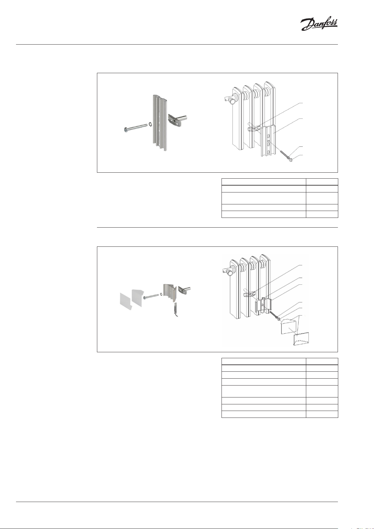
4.8.1 Installation to Sectional Radiator,
direct mounting
• For radiators made from cast iron it is
necessary to apply heat transfer compound
(Electrolube HTS) onto the contact surfaces
of the aluminium profile before installation.
Mount the back plate through the little hole
in the middle.
4.8.2 Sectional Radiator, wall mounting
088H2408
088H2425
088H2420
08 8H 2412
Mounting Accessories Code No.
1 tensioning bracket 088H2408
1 aluminium back plate (supplied with
SonoHCA)
1 cylinder head screw M4 x 40 088H2412
1 spring washer B 4 088H2420
088H2425
• The remote sensor has to be fixed in the
receiver housing with adhesive to avoid
loosening.
• The contact surfaces of the cover angles have
to be coated with adhesive before bringing
them together.
088H2408
Remote sensor
08 8H2410
088H2420
08 8H 2412
088H2406
Mounting Accessories Code No.
1 tensioning bracket 088H2408
1 aluminium profile „receiver housing“ 088H2410
1 spring washer B 4, DIN 128 088H2420
1 cylinder head screw M4 x 40 (with
crosshead)
2 cover angles, white 088H2406
2 plastic dowels Ø5 mm 3.25 (wall) 088H2424
2 oval head wood screws 3 x 35 (wall) 088H2423
088H2412
22 | VU.SH.H1.02 © Danfoss | 2019.03
Page 23
Operating Guide SonoHCA
4.8 Installation of
Fastening Parts Kits
(continuous)
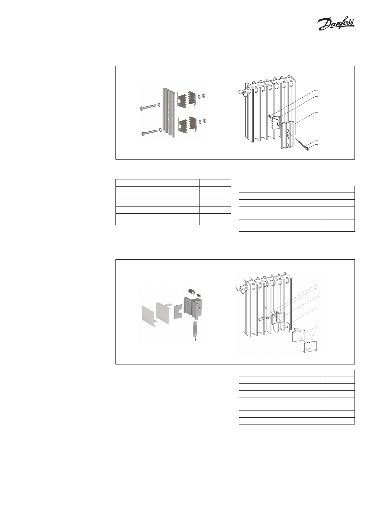
4.8.3 Installation on Folded Radiator
• Mount the aluminium back plate through the
small round hole.
Mounting Accessories Code No.
1 hexagon nut B M4, DIN 934 088H2413
2 bracing angles 088H2421
2 spring washers B4, DIN 128 088H2420
1 oval head screw M4 x 30 088H2411
1 aluminium back plate (supplied with
SonoHCA)
088H2425
08 8H 2413
08 8H2321
088H2425
088H242 0
0 88 H2411
• If necessary use 2 x 2 bracing angles to
improve more stability (photo) and, if needed,
short the screw.
Mounting Accessories Code No.
2 hexagon nut B M4, DIN 934 088H2413
2 x 2 bracing angles 088H2421
4 spring washers B4, DIN 128 088H2420
2 oval head screw M4 x 30 088H2411
1 aluminium back plate (supplied with
SonoHCA)
088H2425
4.8.4 Folded Radiator, wall mounting
• The remote sensor has to be fixed in the
receiver housing with adhesive to avoid
loosening.
• The contact surfaces of the cover angles have
to be coated with adhesive before bringing
them together.
08 8H2 415
08 8H2414
088H24 09
088H2405
088H24 07
Mounting Accessories Code No.
1 tensioning nut 088H2415
1 tensioning bolt 088H2414
1 aluminium profile « receiver housing» 088H2409
1 safety plate 088H2405
2 cover angles, white 088H2407
2 plastic dowels Ø5 mm 3.25 (wall) 088H2424
2 oval head wood screws 3 x 35 (wall) 088H2423
VU.SH.H1.02 | 23© Danfoss | 2019.03
Page 24
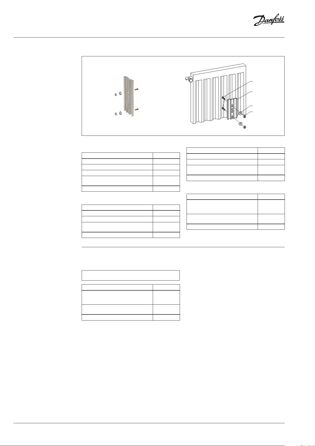
Operating Guide SonoHCA
4.8 Installation of
Fastening Parts Kits
(continuous)
4.8.5 Installation to Panel Type Radiator
• Mount the back plate through the 2 oval holes
adjusted to the top edge of the 2 oval holes.
Mounting Accessories Code No.
2 threaded bolts M3 x 8 (see pag e 19!) 088H2422
2 spring washers B3, DIN 137 088H2418
2 slotted nuts M3, DIN 546 088H2416
1 aluminium back plate (supplied with
SonoHCA)
Tool: Screw driver size 5 for M3
088H2425
or
Mounting Accessories Code No.
2 threaded bolts M3 x 8 (see pag e 19!) 088H2422
2 Nuts M3 6-kant size 5. 5 with flange -
1 aluminium back plate (supplied with
SonoHCA)
Tool: Socket wrench hexagonal size 5.5
088H2425
088H242 2
088H2425
08 8H2418
08 8H2416
or
Mounting Accessories Code No.
2 threaded bolts M3 x 8 (see pag e 19!) 088H2422
2 Nuts M3 mit 6 -kant size 5.5 -
1 aluminium back plate (supplied with
SonoHCA)
Tool: Socket wrench hexagonal size 5.5
088H2425
or
Mounting Accessories Code No.
Silicone glue Pactan 6010,
(Vendor: Tremco Illbruck GmbH & Co. KG
D-92439 Bodenwöhr, T +49 (0) 9434 208 0)
1 aluminium back plate (supplied with
SonoHCA)
Tool: Acetone, Cotton wool
088H2426
088H2425
4.8.6 Mounting of heat cost allocators with
glue
Of using glue for the mounting of heat cost allocator,
please r efer to the Standard EN83 4.
Mounting Accessories Code No.
Silicone glue Pactan 6010,
(Vendor: Tremco Illbruck GmbH & Co. KG
D-92439 Bodenwöhr, T +49 (0) 9434 208 0)
1 aluminium back plate (supplied with
SonoHCA)
Tool: Acetone, Cotton wool
088H2426
088H2425
• Clean the aluminum back plate with Acetone
soaked cotton wool.
• Clean the gluing spot on the radiator with
Acetone soaked cotton wool.
• Before and after the gluing, trash the first and
last 10 cm of glue from the cartridge.
• Assemble the heat cost allocator: Aluminum
back plate to body and seal it.
• Apply 2 tracks of Pactan glue to the aluminum
back plate, left and right of the channel.
• Press the heat cost allocator to dedicated
spot on the radiator and sway the heat cost
allocator to dispense the glue evenly.
• Press firmly and align. Wait 2-3 minutes
check, align and press. Make sure the heat
cost allocator is mounted straight. The heat
cost allocator must hold by itself. After 10
hours the heat cost allocator is firmly glued to
radiator.
• Remove redundant glue with a screw driver.
Clean the radiator with paper towels.
Removal of glued heat cost allocators
• Remove the aluminum back plate with a
screw driver size 2 and a hammer: Position the
screw driver carefully in the middle channel
and hammer until the aluminum plate can be
removed.
• Remove glue carefully with a carpet cutter
and clean glued surface with Acetone.
24 | VU.SH.H1.02 © Danfoss | 2019.03
Page 25

Operating Guide SonoHCA
4.8 Installation of
Fastening Parts Kits
(continuous)
4.8.7 Panel Type Radiator, wall mounting
• The remote sensor has to be coated with heat
transfer compound (Electrolube HTS) on the
contact surface.
088H242 2
Remote sensor
088 H2417
088H2404
Remain inside sensor
Detached part
• Turn on the pull-off nuts 088H2417 till it
breaks. After put on the HK-sensor cover to
ensure the manipulation protection.
088H2424
088H2425
088H2420
088H2423
• Mount the back plate through the 2 oval holes
adjusted to the top edge of the 2 oval holes.
Mounting Accessories Code No.
2 threaded bolts M3 x 8 088H2422
2 pull-off nuts M3 088H2417
1 HK-sensor cover 088H2404
2 plastic dowels Ø5 mm 3.25 (wall) 088H2424
2 oval head wood screws 3 x 35 (wall) 088H2423
4.8.7 Panel Type Radiator, wall mounting
• The contact surfaces of the aluminium
screws have to be coated with heat transfer
compound (Electrolube HTS).
• The aluminium screws have to be fastened
with adhesive to avoid loosening.
088H2425
08 8H2419
Mounting Accessories Code No.
3 sheet-metal screws 2.9 x 9.5 088H2419
1 aluminium back plate 088H2425
VU.SH.H1.02 | 25© Danfoss | 2019.03
Page 26

Operating Guide SonoHCA
4.8 Installation of
Fastening Parts Kits
(continuous)
4.8.9 Bathroom radiator – Towel rails
Heat cost allocator mounted vertically on
distributor or collector part.
• Assembly with 2 threaded bolts welded on
75% BH +50mm on the side or front of the
flow dis-tributor or return collector.
Mounting Accessories Code No.
2 threaded bolts M3 x 8 (see pag e 19!) 088H2422
2 spring washers B3, DIN 137 088H2418
2 slotted nuts M3, DIN 546 088H2416
1 aluminium back plate (supplied with
SonoHCA)
Tool: Screw driver size 5 for M3
088H2425
Heat cost allocator mounted horizontally on
cross tubes
• Assembly to the nearest possible place to the
flow place or return place on the cross tubes
on 75% BH with 2 tensioning brackets .
Mounting Accessories Code No.
2 Equerre de f ixation 088H2408
1 Profil aluminium (livré avec le répartiteur) 088H2425
2 Vis cylindrique M4 x 40 088H2412
2 Rondelles B 4, DIN128 088H2320
26 | VU.SH.H1.02 © Danfoss | 2019.03
Page 27

Operating Guide SonoHCA
4.8 Installation of
Fastening Parts Kits
(continuous)
4.8 Overview mounting
accessories
4.8.10 Sectional Radiator wide
088H2428
088H243 0
088H2427
088H2425
08 8H 2412
088H2429
• Mount the back plate through the 2 oval holes
adjusted to the top edge of the 2 oval holes.
Mounting Accessories Code No.
2 tensioning bracket 50mm 088H2428
2 tensioning bracket 65mm 088H2433
1 aluminium back plate (supplied with
SonoHCA)
Designation Code No.
Replacement seal 1000 pieces 088H2400
088H2425
Mounting Accessories Code No.
1 heat conduc tor aluminium plate 60mm 088H2427
2 cylinder head screw M4 x 40 088H2412
1 cylinder head screw M3 x 10 088H2429
1 Nut M3 088H2430
Aluminium back plate 088H2425
Plastic blind cover 088H2401
Optical head USB 088H2402
Optical head holder 088H2403
Cover for sensor 088H2404
Safety plate 088H2405
Cover angles, white , Sectional radiator (Protection plate white radiator with sections) 088H2406
Cover angles, white , Folded radiator (Protection plate white corrugated radiator) 088H2407
Tensioning bracket (Angle bracket) 088H2408
Aluminium profile «receiver housing» (Aluminium plate case support for corrugated
radiator)
Aluminium profile «receiver housing» (Aluminium plate case support for radiator with
sec tions)
Raised head screw M4 x 30 088H2411
Pan head screw 4 x 40 088H2412
Hexagon Nut B M4, DIN 934 088H2413
Pins 088H2414
Tensioning nut 088H2415
Slotted nuts M3, DIN 546 088H2416
Two -nu ts M3 088H2417
Spring washers B3, DIN 137 088H2418
Tapping screw 2.9 x 9.5 088H2419
Spring washers 088H2420
Angle spreader 088H2421
Headless pins M3 x 8 088H2422
Crosshead wood screws 3 x 35 088H2423
Plastic screw plug Ø5 mm 3.25 088H2424
Aluminium plate case support for front plate radiator 088H2425
Glue Pactan 6010, 2 cartridge 310 ml 088H2426
Heat conductor aluminium plate 60mm 088H2427
Angle bracket 50mm 088H2428
Cylinder screw M3 x 10 088H2429
Nut M3 088H2430
088H2409
088H2410
VU.SH.H1.02 | 27© Danfoss | 2019.03
Page 28
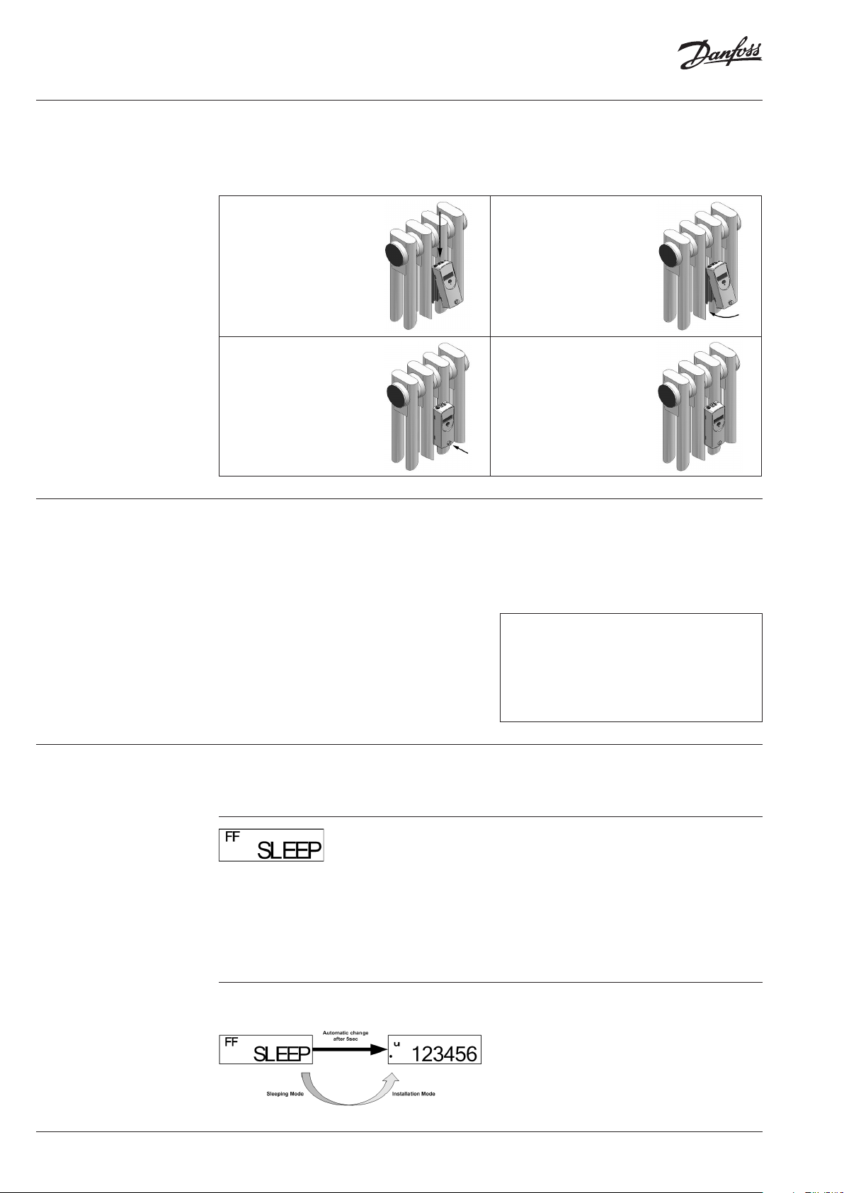
Operating Guide SonoHCA
4.10 Mounting and Sealing
5. Commissioning
After installation of the respective fasteningparts kit to the radiator, the heat cost allocator
can be mounted and sealed by the installer as
described below:
1.
The heat cost allocator is
placed at the upper end of
the aluminium back plate.
Move the heat cost allocator
down so that the hooks in the
housing fit in the aluminium
back plate.
3.
Push the seal preinstalled
by Danfoss in the slot of the
housing, then press until the
seal clicks into the aluminium
back plate.
Ex-factory the heat cost allocators SonoHCA
are in the so-called sleeping mode. In this
mode no measuring is carried out and thus no
consumption values are calculated. Furthermore
the digital display, the radio communication
options as well as the device opening detection
are deactivated. Only the optical communication
interface is available.
The date and time are running in the
background.
2.
The heat cost allocator is
placed on the aluminium back
plate in the direction of the
arrow.
4.
Now the heat cost allocator
can only be opened by
destroying the seal.
Transition from sleeping to installation mode is
achieved by pushing the button once when the
heat cost allocator is mounted on the aluminium
back plate or by an automatic commissioning
during the mounting on the aluminium back
plate.
After the commissioning and before leaving
a new site, we recommend to perform
a radio read out test and to create an
installation protocol, to ensure that all the
radio communication between the heat cost
allocators and the radio central or radio
modem was successful.
5.1 Automatic
commissioning during
the installation
Once heat cost allocator is fixed with/against the
aluminium back plate, the LCD-display will show
the following message:
The index FF indicates that the heat cost
allocator has recognized the remote sensor.
If the remote sensor is not detected by the
device, the index -- will be displayed.
The index -- indicates also a standard device with
a compact sensor.
This message will be displayed during 5 seconds
and after that, the transition from sleeping mode
to installation mode will be done automatically.
Transition from sleeping to installation mode is
achieved automatically after 5 seconds:
The • symbol indicates that the heat cost
allocator is in installation mode.
Once installed on the back plate or the wall, the
heat cost allocator switches automatically from
the installation mode into the operating mode at
the second transition of midnight.
28 | VU.SH.H1.02 © Danfoss | 2019.03
Page 29

Operating Guide SonoHCA
5.2 Commissioning by
pressing push button
5.3 Radio Standby
Once heat cost allocator is fixed with/against the
aluminium back plate, the LCD-display will show
the following message:
The index FF indicates that the heat cost
allocator has recognized the remote sensor.
If the remote sensor is not detected by the
device, the index -- will be displayed.
The index -- indicates also a standard device with
a compact sensor.
This message will be displayed during 2 minutes
before the LCD-display will switch off.
Transition from sleeping to installation mode
is achieved by pushing the push button during
3 seconds:
The • symbol indicates that the heat cost
allocator is in installation mode.
Once installed on the back plate or the wall,
the heat cost allocator switches automatically
into operating mode at the second transition of
midnight.
In order to achieve a user-friendly and powersaving radio standby, the radio heat cost
allocator features the following different
operating modes:
* : SLEEP information will be displayed by pushing the push button.
Transition from sleeping mode to installation
mode is achieved by two different ways:
• Pushing the push button once the heat cost
allocator is mounted on the aluminium back
plate.
• An automatic detection during the mounting
on the aluminium back plate. This function
VU.SH.H1.02 | 29© Danfoss | 2019.03
Page 30

Operating Guide SonoHCA
5.3 Radio Standby
(continuous)
5.3.1 Sleeping Mode
Ex-factory the radio heat cost allocator is in
sleeping mode, but the internal clock and the
date are running.
Current consumption is reduced to a minimum
since no measuring and no calculations are
carried out. Only the optical communication
interface is available.
Transition from sleeping to installation mode is
achieved by pushing the button once the heat
5.3.2 Installation Mode
The • symbol indicates that the heat cost
allocator is in installation mode.
During the installation mode all functions of the
radio heat cost allocator SonoHCA are carried
out.
5.3.3 Operation Mode
The choice of the telegram is done when ordering. It is
not possible to se lect the telegram typ e on the device
itself.
5.3.3.1 Readout over the short telegram
(OMS compliant)
With this operating mode, SonoHCA transmits
data:
• Transmission interval each 120 seconds
(minimum).
• Radio reading, 24h/24h.
cost allocator is mounted on the aluminium back
plate or by an automatic commissioning during
the mounting on the aluminium back plate (must
be specified when ordering).
When the device switches from sleep mode to
installation mode, the following counters are
automatically reset to zero:
• Current totaliser, totaliser at set day, historical
totaliser values.
• Max. radiator temperature.
• For heat cost allocator SonoHCA, an
installation telegram is activated during the
installation phase. Data are transmitted each
30 seconds (short and long telegram) till at
the end of the second day at midnight.
The radio heat cost allocator SonoHCA switches
automatically into operating mode at the end of
the second day at midnight.
If heat cost allocator is removed from the aluminium back
plate during the installation mode, the heat cost allocator
switches to the sleeping mode.
5.3.3.2 Readout over the long telegram for
Walk-by reading
With this operating mode, the SonoHCA
transmits data:
• Transmission interval each 120 seconds
(minimum).
• Radio reading and periods, 12h per day
(programmable), 7days/7days.
6. Readout
The current and monthly values recorded by the
heat cost allocator SonoHCA as well as several
other parameters can be readout over the optical
interface or also over radio.
The following parameters are transmitted:
Optical Interface:
• Identification number (information in header).
• Date and time.
• Consumption value.
• Set Day.
• Set Day value.
• Maximum radiator temperature of previous
heating period.
• 36 monthly values and 18 half monthly values
for cumulated consumption.
• Rating factor KC.
• Rating factor KQ.
• Current radiator temperature.
• Current ambient temperature.
• Maximum radiator temperature of the current
heating period.
• Manipulation protection:
- Duration of the manipulations.
- Date of the last manipulation.
- Manipulation counter.
• Error code.
• Firmware version.
• Commissioning date.
• State of parameters.
• 36 half monthly values for the average
ambient temperature.
• 18 monthly values for the maximum radiator
temperature.
30 | VU.SH.H1.02 © Danfoss | 2019.03
Page 31

Operating Guide SonoHCA
6. Readout (continuous)
6.1 Remote Radio
Reading
The following parameters are transmitted by
SonoHCA wM-Bus:
Short telegram, OMS compliant :
• Identification number (information in header).
• Date and time.
• Consumption value.
• Set Day.
• Set Day value.
• Error code.
• Current radiator temperature.
• Current ambient temperature
• State of parameters.
Long telegram for Walk-by reading:
• Identification number (information in header).
• Date and time.
• Consumption value.
6.1.1 General Information about the Remote
Radio Readout
The transmission of radio data depends on the
technical specifications of the buildings and their
surroundings. Due to these external factors, a
readout may not be possible at certain times and
in certain locations. It is solely incumbent on the
user to check the radio propagation conditions
at the planned installation point.
• Set Day.
• Set Day value.
• 18 monthly values for the cumulated
consumption.
• Current radiator temperature.
• Current ambient temperature.
• Manipulation protection:
- Manipulation counter.
• Error code.
• Commissioning date
• State of parameters.
AES 128 bits encryption is available for all radio
versions.
Short or long telegram rad io wM-Bus
The choice of the telegram is done when ordering. It is
not possible to se lect the telegram typ e in the device
itself.
6.1.2 WireIess M-Bus Remote Radio Readout
The Wireless M-Bus radio communication
interface enables data to be relayed using Wire
less M-Bus radio protocol (EN 13757-4) and
complies with open metering system (OMS)
specifications version V3.0.1.
The SonoHCA uses one-way radio technology
and transmits the consumption data and
saved settings every 120 seconds for short (OMS)
or long (walk-by) telegrams.
Since the SonnHCA radio heat cost allocator uses
one-way radio technology, it must be
used with a SonoRead 868 mobile data receiver
and a smartphone with the SonoAPP software
program.
6.1.3 Readout using the Radio Central
SonoCollect
The radio central Wireless M-Bus SonoCollect
receives radio data from the SonoHCA or from
other Wireless M-Bus devices.
As the SonoHCA uses one-way radio technology,
it must be used with a SonoCollect Wire-less
M-Bus and a PC with the corresponding software
program.
VU.SH.H1.02 | 31© Danfoss | 2019.03
Page 32

Operating Guide SonoHCA
7. Rating factors
7.1 Taking Measurements
The value displayed by the heat cost allocator
has to be converted to the value of the actual
heat output of each radiator. Thereby the design
and the performance of the radiator as well as
the mode of installation have to be taken into
account.
Therefore each radiator has to be identified
precisely by taking measurements. The following
data have to be established:
• Design and make of radiator
• Overall length
• Overall height
• Overall depth
• Number of sections
• Pitch
• In-line configuration
7.1.2 Rating of Radiator
For each radiator type the K-value is calculated
according to the following diagram:
7.1.1 Rating of Radiators with Over Length
or High Nominal Power
If the radiator has an overall length of approx. 3
m we strongly recommend installing two heat
cost allocators.
Under certain circumstances minimal flows
might not be noticed on these radiators. The
same applies for radiators with an extremely
high nominal output of more than 10.0000 watt
= 10kW.
At least two heat cost allocators should be
installed to these radiators. The standard
performance of each radiator is divided by the
number of heat cost allocators installed.
Example:
Standard performance KQ= 16.000 W = 16
Number of heat cost allocators installed to the
radiator = 2
KQ individual = 16 / 2 = 8
The heat cost allocator determines the heat
output of the radiator, displays the consumption
and records the consumption values on the set
day.
The heating medium temperature is captured by
the temperature sensor installed to the radiator.
Thus the heat output of the radiator is calculated
in consideration of the radiator performance.
These calculations are started as soon as the
temperature difference between ambient
temperature and heating medium temperature
is bigger than the parameterised value.
Out of this functional principle the necessity
arises to rate the display of the heat cost
allocator. For the calculation of the heat output
of the radiator it is not sufficient to measure the
heating medium temperature. Radiators with
different performances also feature different
medium temperature is the same. Furthermore
different designs lead to different measuring
conditions for the temperature sensor installed
to the radiator.
K: Rating factor total
KQ: Rating factor for the standard performance
of the radiator, stated in KW. This value is
calculated with the data received by taking
measurements and the manufacturer’s data.
KC: Rating of the C-value of the radiator
temperature sensor. For each type of
radiator this value is measured on the test
rig. The respective KC-value can be taken
from the table with the rating factors.
KT: Rating of the design ambient temperature.
Normally KT = 1.
For the definition of the rating factors according
to EN 834, please see chapter 9.3.
heat output quantities even if the heating
32 | VU.SH.H1.02 © Danfoss | 2019.03
Page 33
Operating Guide SonoHCA
7.2 Table of Rating
Factors
7.3 Rating Factor
according EN
834: 2013
A detailed summary of Kc values in Excel / PDF
format is available upon request.
There is also a PC software program available at
the following website:
http://www.thermosoft2000.de/eng/
Excerpt
Rating factor (Chapter 3.36):
With the following rating factors the display
values of each heat cost allocator can be
converted into consumption values which are
suitable to be used for billing the heating costs
according to consumption.
Rating factor KQ for the heat output of the
radiator (Chapter 3.37 and 5.3.1):
The rating factor KQ is the (non-dimensional)
numerical value of the standard performance of
the radiator stated in watts or kilowatts.
The thermal output of a radiator in a thermally
stable test booth at flow, return and air
temperatures of 90 °C, 70 °C and 20 °C, the air
temperature being measured at a height of
0,75 m above the floor and a distance of 1,5 m
in front of the heating surface, is the reference
output relevant for the rating factor KQ (reference
system Q(60 K)).
Rating factor KC for the thermal coupling of
the sensors (Chapitre 3.38 et 5.3.2):
The rating factor Kc takes into account the
different thermal couplings to the temperature
sensors and the different designs of the effective
heating surfaces.
Kc is calculated as the quotient of the basic
counting rate RB and the counting rate RE at the
temperatures of the sensors on the radiator to be
rated operated at base condition:
Rating factor KT for rooms with low design
ambient temperatures which deviate
from the basic reference air temperature
(Chapter 3.39)
For heat cost allocators with the single sensor
measuring system, the rating factor KT takes
into account the change in performance and the
change in temperature of the sensors at design
ambient temperatures which are lower than the
reference temperature.
Resulting Rating Factor K (Chapter 5.3.3)
The overall rating factor K is received by
multiplying the individual rating factors:
VU.SH.H1.02 | 33© Danfoss | 2019.03
Page 34

Operating Guide SonoHCA
34 | VU.SH.H1.02 © Danfoss | 2019.03
Page 35

Operating Guide SonoHCA
VU.SH.H1.02 | 35© Danfoss | 2019.03
Page 36
Operating Guide SonoHCA
© Danfoss | DHS-SRMT/SI | 2019.0336 | VU.SH.H1.02
 Loading...