

Installation Guide
HDU-SF (Horizontal Distribution Units - Single Flat)
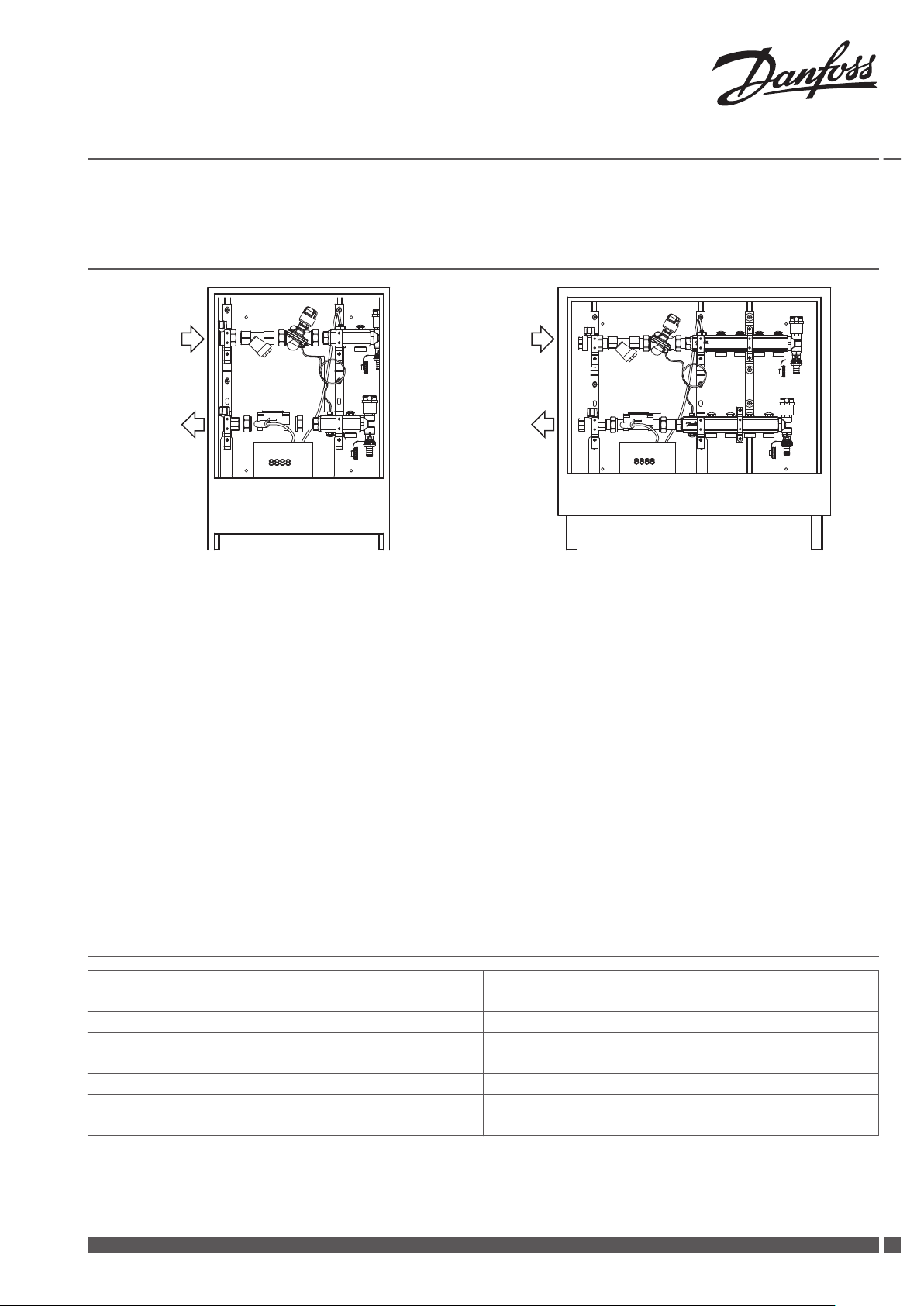
1 Introduction
HDU-SF single-port HDU-SF multi-port
1. Ball valve for in- and outlet connection to the riser.
2. Strainer to trap dirt, sand etc. from pipe water (replacement filter available as accessory).
3. AB-PM automatic balancing valve, combines three functions: differential pressure controller, control valve with linear characteristic and
flow limiter.
4. Manifold for radiator connection, flow.
5. Manifold for radiator connection, return.
6. Automatic air vent and drainage (both inlet and outlet has drainage and air vent possibilities).
7. Heat Meter for energy measuring, with 8-digit LCD.
8. Cabinet.
Note!
The HDU-SF must only be installed in a dry and frost-free environment.
▪
Operation of the HDU-SF outside the specified operating and environmental conditions is not permitted.
▪
Joints may be loose after transportation. Please check and re-tighten, if necessary.
▪
HDU-SF are available with left or right side connections to riser. All illustrations are shown for the left side version.
▪
Service guide is placed on the inside of the cabinet door.
▪
2 Technical Data
Max. temperature 90 °C
Max. working pressure in heating system piping before the unit 2 bar
Nominal required differential pressure over unit (HDU-SF) 0.26 bar*
Max. differential pressure in a control loop 0.22 bar
Max. static pressure 10 bar (PN 10)
Connection to riser (in and out) R 3/4"
Connection to manifold (out) 3/4"
Power supply (Heat Meter) A-cell battery, 3.6 VDC
* At differential pressure in control loop 10kPa at 100% AB-PM setting.
Danfoss Heating Solutions VIIGA102
1
260
380
51
49
2389
72
25
95
125
480
380
62
95
51
49
23
213
113 200
266
50
25
125
B
A
Installation Guide HDU-SF (Horizontal Distribution Units - Single Flat)
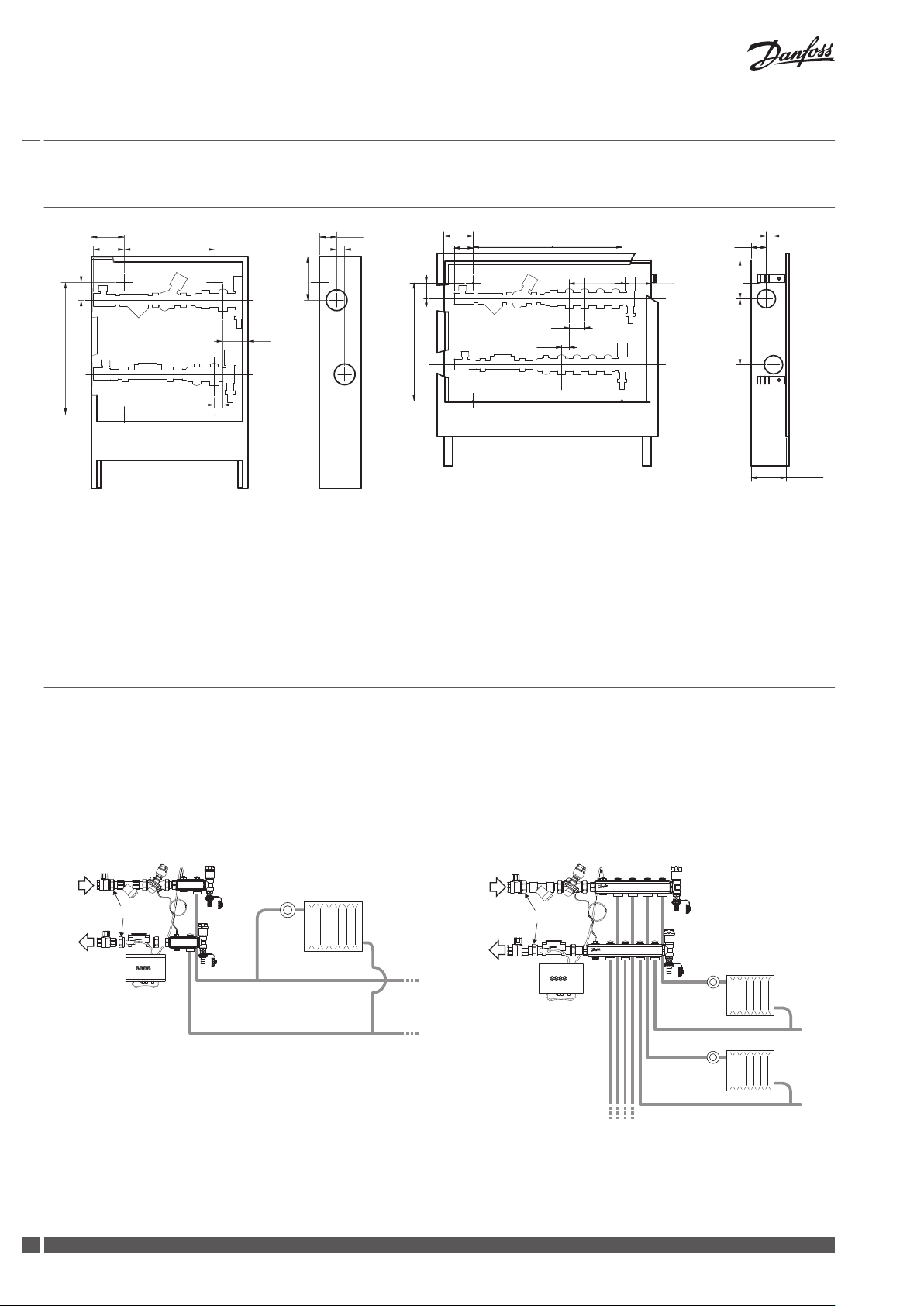
3 Mounting on Wall
HDU-SF single-port HDU-SF multi-port
HDU-SF 4-port
A = 480 mm
HDU-SF 7-port
A = 630 mm
The HDU-SF is mounted vertically, tilted angle is to be checked with a spirit level. Available for wall or recess mounting, depth can be
regulated by moving the face frame. The cabinet has four holes in the back plate, intended for mounting with the supplied screws and
rawlplugs.
4 Connections
4.1 Connection to riser
Connect the HDU-SF to the riser according to flow direction:
1. Riser inlet
2. Riser outlet
3. The connections are size DN20 with internal thread. Remember backstop to prevent the ball valves from loosening.
HDU-SF single-port
HDU-SF multi-port
2
VIIGA102 Danfoss Heating Solutions

Installation Guide HDU-SF (Horizontal Distribution Units - Single Flat)
4.2 Connection to radiator
Connection of system pipes to the HDU-SF manifold should be made with compression fittings, DN should be chosen according to the
piping type and diameter.
1. Mount fittings by hand. 2. Tighten with spanner, max. ½ to 1 turns.
Danfoss recommends using the following compression fittings:
Compression fittings Size Code no.
for PEX tubing
(in accordance with ISO 15875)
for AluPEX tubing
for steel and copper tubing
- PN6
- G ¾” internal thread
- PN10
- G ¾” internal thread
- PN10
- G ¾” internal thread
16 x 2 mm 013G4156
20 x 2 mm 013G4160
20 x 2.25 mm 013G4093
20 x 2.5 mm 013G4161
16 x 2 mm 013G4186
20 x 2 mm 013G4190
20 x 2.25 mm 013G4093
20 x 2.5 mm 013G4191
16 mm 013G4126
18 mm 013G4128
5 Check and Test
1. Ensure that the capillary tube in AB-PM valve is mounted correctly.
2. Fill the system with water and make sure that all connections
are tight and without leaks.
3. Check function of the Heat Meter. The meter will only measure energy if the pipes are completely filled with water, otherwise a corresponding error message (E - 7) is shown in the
display.
4. Check the flow rate display for plausibility. If the flow rate display is not steady, bleed the system. Regulate the system using the flow rate display.
5. Read the meter counts for energy, volume and operating
hours.
Error messages for wrong installation
E - 3: Temperature sensors reversed during installation or connection.
E - 6: Heat meter has not been installed in the intended flow direction.
Note! Please refer to the Service Guide (placed on the inside of the
cabinet door) for other error codes.
HDU-SF single-port
Danfoss Heating Solutions VIIGA102
HDU-SF multi-port
3

10%
100%
≠
h
h+ 2 mm, DN 15-20
h+ 4 mm, DN 25
1.5 mm
Installation Guide HDU-SF (Horizontal Distribution Units - Single Flat)
6 Settings
Setting of the AB-PM is done during the commissioning. The ABPM automatic balancing valve is set to the wanted flow by
turning the top of the valve (or more information, please refer to
separate data sheet for AB-PM).
Push down on the top to lock the AB-PM settings.
To unlock, simply lift up the top.
Danfoss A/S
Heating Solutions
Haarupvaenget 11
8600 Silkeborg
Denmark
Phone:+45 7488 8000
Fax: +45 7488 8100
Email: heating.solutions@danfoss.com
www.heating.danfoss.com
Danfoss can accept no responsibility for possible errors in catalogues, brochures and other printed material. Danfoss reserves the right to alter its products without notice. This also applies to products
already on order provided that such alterations can be made without subsequential changes being necessary in specifications already agreed. All trademarks in this material are property of the respective
companies. Danfoss Heating Solutions and the Danfoss Heating Solutions logotype are trademarks of Danfoss A/S. All rights reserved.
013R2142 & VIIGA102 Produced by Danfoss Heating Solutions © 08/2012
 Loading...