

Page 1
MAKING MODERN LIVING POSSIBLE
Service
Guide
HDU-SF (Horizontal Distribution Units - Single Flat)
www.heating.danfoss.com
Page 2

Danfoss A/S is not liable or bound by warranty if these
instructions are not adhered to during installation or service.
The English language is used for the original instructions.
Other languages are a translation of the original instructions.
(Directive 2006/42/EC)
© 2012 Copyright Danfoss A/S
Page 3
Service Guide HDU-SF (Horizontal Distribution Units - Single Flat)
Table of Contents
1 Introduction .................................................................... 3
2 Drain and Vent .................................................................. 4
3 Replacing the Strainer Filter ......................................................... 5
4 Shutting off the Flow .............................................................. 5
5 Heat Meter ..................................................................... 5
6 Replacing the Heat Meter ........................................................... 11
1 Introduction
1.1 Overview
1.1 Overview .................................................................. 3
1.2 Technical Data ............................................................... 4
1.3 Accessories and Spare Parts ...................................................... 4
5.1 General .................................................................... 5
5.2 Power Supply ................................................................ 6
5.3 Operation .................................................................. 6
5.4 Display Indications ............................................................ 7
5.5 Error Codes ................................................................. 8
5.6 Extension Modules ............................................................ 8
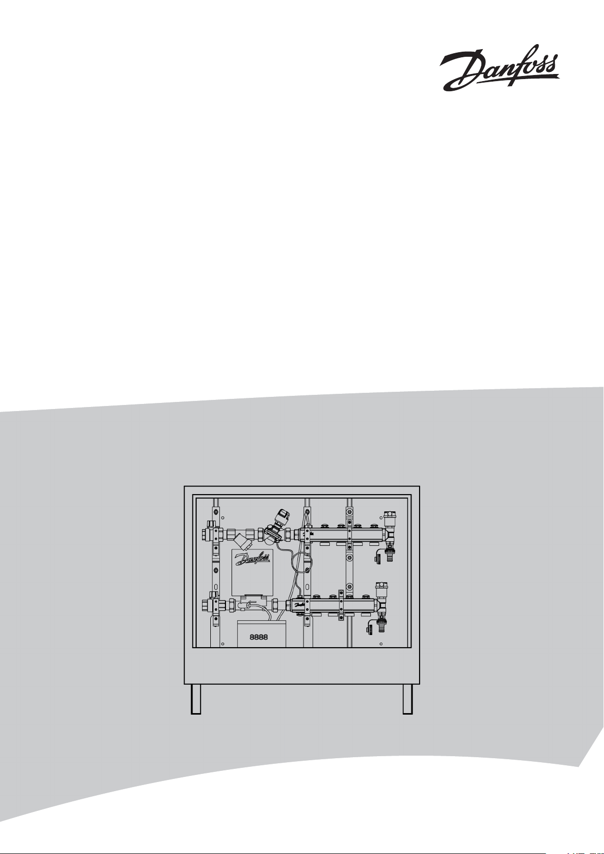
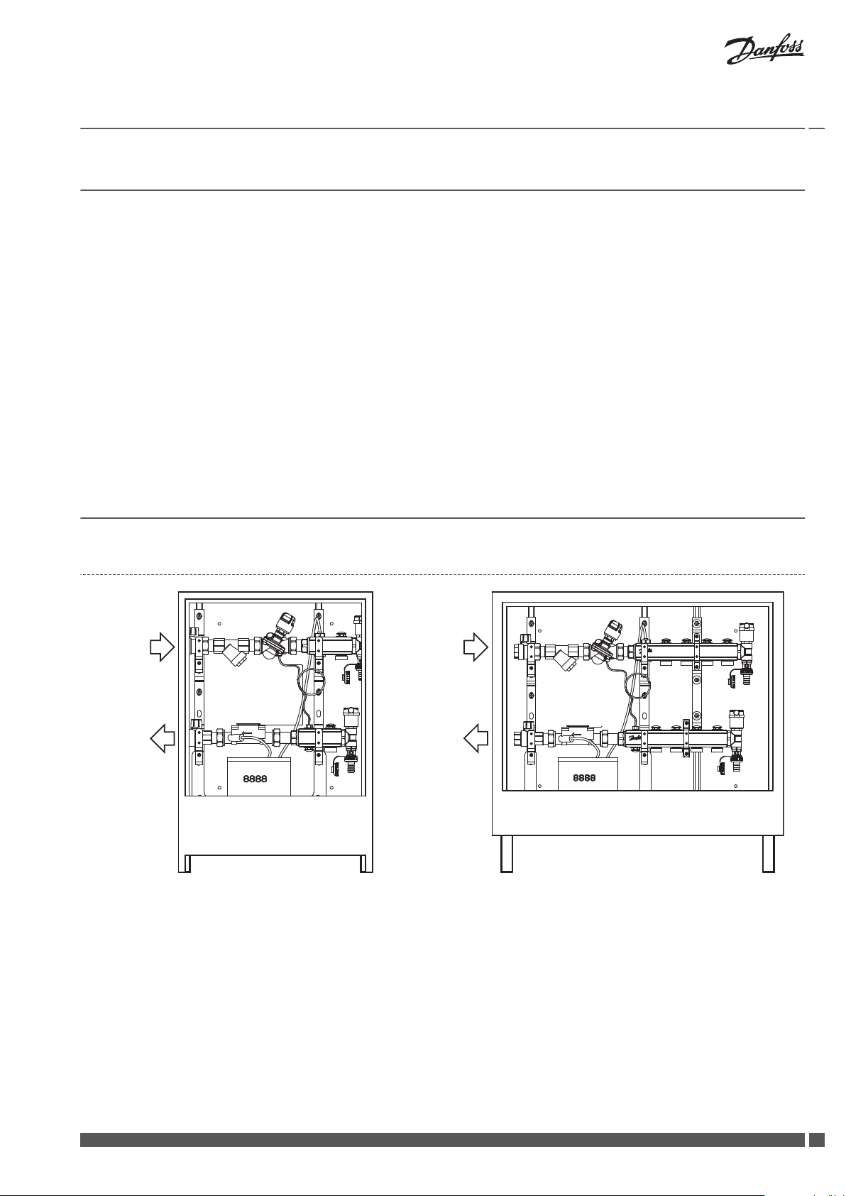
HDU-SF single-port HDU-SF multi-port
1. Ball valve for in- and outlet connection to the riser.
2. Strainer to trap dirt, sand etc. from pipe water (replacement filter available as accessory).
3. AB-PM automatic balancing valve, combines three functions: differential pressure controller, control valve with linear characteristic and
flow limiter.
4. Manifold for radiator connection, flow.
5. Manifold for radiator connection, return.
6. Automatic air vent and drainage (both inlet and outlet has drainage and air vent possibilities).
7. Heat meter for energy measuring, with 8-digit LCD.
8. Cabinet.
Danfoss Heating Solutions VIIGB102
3
Page 4
Service Guide HDU-SF (Horizontal Distribution Units - Single Flat)
Note! HDU-SF are available with left or right side connections to riser. In this Service Guide all illustrations are shown for the left side
version.
1.2 Technical Data
Max. temperature 90 °C
Max. working pressure 2 bar
Nominal required differential pressure over Unit (HDU-SF) 0.26 bar*
Max. differential pressure in a control loop 0.22 bar
Max. static pressure 10 bar (PN 10)
Connection to riser (in and out) R 3/4"
Connection to radiator 3/4"
Power supply (Heat meter) A-cell battery, 3.6 VDC
* At differential pressure in control loop 10kPa at 100% AB-PM setting.
1.3 Accessories and Spare Parts
Product Code no.
Manifold port plugs (10 pcs.) 003L1246
Filter for strainer 065B8248
Impulse tube with fittings for AB-PM 003L8152
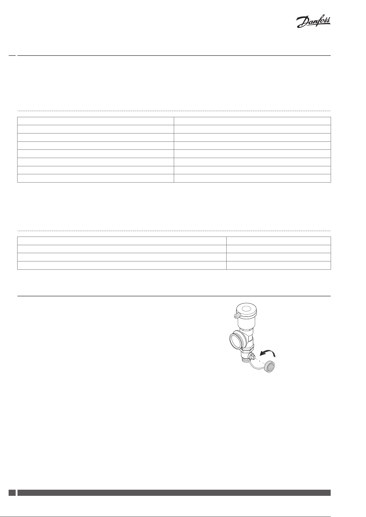
2 Drain and Vent
For draining the inlet and outlet:
close ball valves on supply and return inlet pipes.
▪
use the cap hanging on the drain to open the drain.
▪
The HDU-SF is automatically vented, if necessary.
4
VIIGB102 Danfoss Heating Solutions
Page 5
SONOMETER™1100
Heat meter
Made in Germany
3030716
087G6103
Installation: high temp.
S/N: 41598383
qs: 5m3/h
qp: 2.5m3/h
qi: 0.025m3/h
PS/PN: 16
DN20 IP54
Θq: 5...130°C
Θ: 1....180°C
ΔΘ: 3...177K
Pt 500
class 2
E1 / M1
P.-Year 2012
GPM
V
ΔT Δ
T
-V
Service Guide HDU-SF (Horizontal Distribution Units - Single Flat)
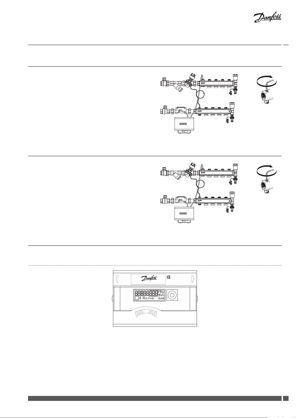
3 Replacing the Strainer Filter
1. Close ball valves on supply and return inlet pipes.
2. Close all inlet manifold circuits after the AB-PM, using a 5 mm Al-
len key.
3. Remove the strainer cap and replace the filter.
4 Shutting off the Flow
1. Close both ball valves to shut off all radiator circuits in the apartment.
2. Use the manual shut off in the manifold to close a single radiator
circuit., using a 5 mm Allen key. Make sure to close both inlet and
outlet for the circuit.
5 Heat Meter
5.1 General
The following guidelinesmust be observed:
The cables supplied with the meter must not be shortened or changed in any other way.
▪
The regulations on the use of energy meters must be observed!
▪
The meter installation is only to be performed by an authorized installer and/or electrical contractor using personnel trained in the
▪
installation and use of electrical equipment and familiar with the Low Voltage Directive.
The specified operating/ambient conditions are 5 … 55 °C; IP54; 93 % rel. humidity.
▪
The IZAR@SET software is used for readout/parametrization.
Danfoss Heating Solutions VIIGB102
5
Page 6

GPM
V
ΔT Δ
T
-V
ΔT
-V
Service Guide HDU-SF (Horizontal Distribution Units - Single Flat)
5.2 Power Supply
A 3.6 V DC lithium battery is fitted in the heat meter.
▪
The battery is not to be charged or short-circuited.
▪
Ambient temperatures below 40 °C extend the life of the battery.
▪
Used batteries must be disposed of according to the applicable regulations.
▪
Caution!
Risk of explosion if the battery is replaced by an incorrect type.
5.3 Operation
Display
The meter readings are displayed with units and symbols on an 8-digit LCD.
1. Quadrant display
2. Loop display
3. Tarif enrgy
4. Error symbol
5. Maximum values
6. Flow rate indicator
Simple operation
A pushbutton mounted on the front of the meter is used to switch to the
various displays.
To show the data read out by the integrator in the display (e.g. amount of
energy, operating hours, volume of water, current temperatures, …)., various windows that can be called up in succession are used.
The meter has 6 different display loops: main loop, set day loop, information loop, pulse input loop, tariff loop and month loop.
The window content of each loop is programmed with the standard information ex works. Various display windows comprise two (seven) displays
that change successively at intervals of 2 - 4 s. The loops in the display are
numbered from 1 to 6 to help the user find his way around quickly. The
main loop (loop 1) is programmed with the current data as default setting,
e.g. for energy, volume, flow rate.
1. Loop display (for loop 1)
A few fragments of the loops or even whole loops can be turned off, using
the IZAR@SET software. It simplifies arrangement of the windows.
The pushbutton is used to switch through the various displays. The button can be pressed for a short or a long time:
Button press Result
Short press (< 3 seconds) Switches to the next display within a loop
Long press (> 3 seconds) Switches to the next display loop
Button not pressed for 4 minutes Meter switches off the display automatically (to save power, but only if no error exists)
Button pressed again Meter shows the basic display
6
VIIGB102 Danfoss Heating Solutions
Page 7

Service Guide HDU-SF (Horizontal Distribution Units - Single Flat)
5.4 Display Indications
Loop Sequence Window 1 Window 2
"1"
Main loop
Loop Sequence Window 1 Window 2 Window 3
"2"
Accounting date loop
1.1 Accumulated energy
1.2 Volume
1.3 Flow
1.4 Power
1.5 Forward temperature Return temperature
1.6 Difference temperature
1.7 Operating days
1.9 Error status
1.10 Display test
2.1 Accounting date 1 (date 1) Accounting date 1 energy 'Accd 1A'
2.2 Next accounting date 1 (date 1) Next accounting date 1 energy 'Accd 1L'
2.3 Previous accounting date 1 (date 1) Previous accounting date 1 energy 'Accd 1'
2.4 'Accd 1' Date of next accounting date 1
2.5 Accounting date 2 (date 2) Accounting date 2 energy 'Accd 2A'
2.6 Next accounting date 2 (date 2) Next accounting date 2 energy 'Accd 2L'
2.7 Previous accounting date 2 (date 2) Previous accounting date 2 energy 'Accd 2'
2.8 'Accd 2' Date of next accounting date 2
Loop Sequence Window 1 Window 2
"3"
Info loop
Loop Sequence Window 1 Window 2 Window 3
"4"
Pulse input loop
Loop Se-
"5"
Tariff loop
Loop Se-
"6"
Monthly value loop
quence
quence
6.24 'Date month - 23' date month - 23 Energy Tariff 1 Tariff 2 Volume
3.1 Current date
3.2 'SEC_Adr' Secondary address
3.3 'Pri_Adr 1' Primary address 1
3.4 'Pri_Adr 2' Primary address 2
3.5 Installation position
3.6 'Port 1' No. of the mounted module at port 1
3.7 'Port 2' No. of the mounted module at port 2
3.8 Status integrated radio (Sequence will be shown only in meters with integrated radio)
3.9 No. of error hours
3.10 'F01-001' (software version) Checksum
4.1 'In1' Accumulated values pulse input 1 'PPI' pulse value 1
4.2 'In2' Accumulated values pulse input 2 'PPI' pulse value 2
Window 1 Window 2 Window 3 Window 4 Window 5 Window 6 Window 7
The tariff loop is switched off as a standard at the heat meter or meter for cooling.
Window 1 Window 2 Window 3 Window 4 Window 5 Window 6
6.1 'Date last month' Accumulated ener-
6.2 'Date month - 1' date month - 1 Energy Tariff 1 Tariff 2 Volume
6.3 'Date month - 2' date month - 2 Energy Tariff 1 Tariff 2 Volume
...
... ...
gy
Energy Tariff 1 Tariff 2 Volume
Danfoss Heating Solutions VIIGB102
7
Page 8

Service Guide HDU-SF (Horizontal Distribution Units - Single Flat)
5.5 Error Codes
The error code is displayed in the main loop if an error occurs.
The error display disappears automatically as soon as the cause of the error has been cleared. All errors present longer than 6 minutes
are saved in the error log.
Error display Error description
C - 1 Basic parameter error in flash or RAM
E 1 Temperature measuring error
temperature range exceeds [-9.9 C...190 C]
▪
sensor short-circuit
▪
sensor break
▪
E 3 Forward and return sensor reversed
E 4 Hardware error in ultrasonic measurement
transducer/drive defective
▪
transducer/drive short-circuit
▪
E 5 Communication not possible (too frequent reading)
E 6 Wrong direction of flow in volume measuring component
E 7 No primary power supply (only if mains unit used)
Supply is via back-up battery
E 8 Warning! Battery almost flat. Battery should be replaced.
E 9 Warning! Battery almost flat. Battery should be replaced.
E A* Leakage: pipe break detected
E b* Leakage: leakage detected in energy meter
E C* Leakage: leakage pulse input 1
E d* Leakage: leakage pulse input 2
* optional
5.6 Extension Modules
The Heat Meter has two slots for extension modules. These modules have no effect on consumption recording and can be fitted without
damaging the verification mark.:
Slot 1 Slot 2
Pulse In (2x) Pulse In (2x)
Pulse In (2x) / Out (1x) Pulse Out (2x)
RS232 Pulse In (2x) / Out (1x)
M-Bus RS232
RS485 M-Bus
L-BUS (for external radio) RS485
Analogue Out (4-20 mA) L-BUS (for external radio)
8
VIIGB102 Danfoss Heating Solutions
Page 9

Attention!
Keep free a
t
radio version!
Slot 1
Slot 2
Test Output
Service Guide HDU-SF (Horizontal Distribution Units - Single Flat)
Installation of modules
1. Open the integrator by releasing the side catches.
2. Engage the module in the relevant slot and carefully connect the preformed ribbon cable at both ends.
3.
Close the lid and check the meter for correct operation by pressing the
push button.
Communication modules (upon order)
The meter supports two communication channels over the same or different interfaces. An additional communication module can be
used in radio operation. The protocol is different for each of the two channels and is preset ex works, but can be set to customer-specific
requirements using the IZAR@Set software.
Each channel has its own primary address, but only one secondary address exists, which is set to the serial number ex works.
M-Bus
The M-Bus communication module is a serial interface for communication
with external M-Bus control centre. The module contains a 2-pole terminal
strip with terminals marked 24, 25, which are connected to M-Bus control
centre.
M-Bus protocol to EN 1434-3 standard:
Connection for 2 x 2.5 mm² wires
▪
The connection is electrically isolated
▪
Current drawn: one M-Bus load
▪
L-Bus
The L-Bus module is an adapter for an external radio module. Packet length can be configured, conforms to EN1434-3. Data reading
and parametrization are carried out using two-wire scheme with different polarity.
Communication over radio
The integrated radio module is an interface for communication with Hydrometer radio receivers.
Unidirectional communication has the following specification:
The module sends every 6 ... 25 s (variable, depending on protocol length)
▪
The radio module always accesses the current meter registers
▪
Transmission frequency: 868 MHz or 434 MHz
▪
Various Hydrometer receivers are available for receiving the protocol (e.g. Bluetooth, GPRS, LAN, …)
▪
The protocol corresponds to the Open Metering or HYD standard and is encrypted
▪
Reading modes: walk-by, drive-by, fixed network
▪
RS232 communication module
The RS232 communication module is a serial interface for communication
with external devices, e.g. PC.
The module contains a 3-pole terminal strip with terminals marked 62(Dat),
63(Req) and 64(GND). A special adapter cable is required for connection
(order no. 087H0121). The coloured wires are to be connected as shown:
62 = brown
▪
63 = white
▪
64 = green
▪
Danfoss Heating Solutions VIIGB102
9
Page 10

V
cc
Pulse
GND
Pu
lse
output
module
Energy external
meter
Service Guide HDU-SF (Horizontal Distribution Units - Single Flat)
RS485 communication module
The RS485 communication module is a serial interface for communication
with external devices, e.g. PC.
The module contains a 4-pole terminal strip with terminals marked D+, Dund +12-. The module needs an external power supply of 12 V DC ±5 V.
Pulse input function module
Module for two additional pulse counters. The module contains a 4-pole
terminal strip with pulse input 1 marked as “I1 - |_” and input 2 as “I2 - |_”.
Pulse inputs 1 and 2 are programmable for a value of: 1, 2.5, 10, 25,
▪
100, 250, 1000, 2500 litres per pulse.
Possible units are all the energy units available in the meter, the vol-
▪
ume unit m³ or no unit
Input frequency is in the range < 8 Hz.
▪
Min. pulse duration 10 ms.
Input resistance 2.2 MΩ.
▪
Terminal voltage 3 V DC.
Data is accumulated separately in registers
▪
Data is readable as IN1 and IN2 in the display and can be transmitted
▪
over the communication modules
Cable length up to 10 m
▪
Pulse output function module
The module contains connections for 2 pulse outputs, , proportional to the
flow or heat consumption. The module contains a 4-pole terminal strip with
pulse input 1 marked as “O1 - |_” and input 2 as “O2 - |_”.
External supply: Vcc = 3-30 V DC
Output current < 20 mA with a residual voltage of < 0.5 V Open collector
(drain) Electrically isolated Output 1: f < 4 Hz
Pulse duration: 125 ms ±10 %
Pulse break: > 125 ms –10 %
Output 1:
Output frequency: f < 4 Hz
▪
Pulse duration: 125 ms ±10 %
▪
Pulse break: > 125 ms –10 %
▪
Output 2:
Output frequency: f < 100 Hz
▪
Pulse duration
▪
Pulse break ~1:1
▪
Volume pulse value is programmable as desired
▪
10
VIIGB102 Danfoss Heating Solutions
Page 11

Heat meter
Made in Germany
303
0716
087G6103
Installation: high temp.
S/N: 41598383
qs: 5m3/h
qp: 2.5m3/h
qi: 0.025m3/h
PS/PN: 16
DN20 IP54
Θ
q: 5...130°C
Θ: 1....180°C
ΔΘ: 3...177K
Pt 500
class 2
E1 / M1
P.-Year 2012
GPM
V
ΔT Δ
T
-V
Heat meter
Made in Germany
3030716
087G6103
Installation: high temp.
S/N: 41598383
qs: 5m
3
/h
qp: 2.5m
3
/h
qi: 0.025m
3
/h
PS/PN: 16
DN20 IP54
Θ
q: 5...130
C
Θ
: 1....180
C
ΔΘ
: 3...177K
Pt 500
class 2
E1 / M1
P.-Year 2012
GPM
V
Δ
T ΔT
-V
SONOMETER™1100
087G6103
P.-Year 2012
Service Guide HDU-SF (Horizontal Distribution Units - Single Flat)
Combined function module
The combined module is equipped with 2 inputs and 1 output.
The pulse input specification is the same as that of the pulse input module
above.
The pulse output specification is the same as pulse output module above,
but not electrically isolated.
Analogue output function module
The module contains connections for 2 passive analogue outputs, which
can be programmed as desired using the IZAR@SET software. The outputs
are marked on the terminal strip as “1” and “2” with the respective polarity
“+” and “–”. When connecting to outputs, one should observe polarity.
Passive analog output
▪
External power supply: 10…30 V DC
▪
Current loop 4 … 20 mA
▪
Errors are generated at 3.5 mA or 22.6 mA (programmable)
▪
Output values: power, flow rate, temperatures
▪
Test output
This test output located on the side is intended for use by test centres. The manufacturer provides two special cables for this: 1. Volume
test pulses and 2. Energy test pulses. Other specifications (pulse value, pulse duration/break, pulse frequency) can be obtained from
the Inspection and Test Instruction.
6 Replacing the Heat Meter
Ordering a new Heat Meter
A new Heat Meter can be ordered at Danfoss by using the informations on
the existing Heat Meter:
1. Product name
2. Ordering number
3. Production year
Removing the existing Heat Meter
1. Close both shut-off valves.
2. Manually close all ports on the return manifold with a 5 mm Allen key.
Loosen the Allen screw and pull out the temperature sensor from the
3.
manifold pocket.
4. Remove the Heat Meter electronic by sliding it off the bracket.
5. Remove the brass part from the return flow (remember backstop to
prevent the shut-off valves from loosening).
Danfoss Heating Solutions VIIGB102
11
Page 12

Service Guide HDU-SF (Horizontal Distribution Units - Single Flat)
Installing a new Heat Meter
1. Install the brass part, use 2 new flat gaskets and remember backstop
to prevent the ball valves from loosening. Make sure the arrow is
placed in accordance with the flow direction.
2. Slide the Heat Meter electronic onto the bracket.
3.
Handle the temperature sensors with care! Make sure that the sensor
is inserted as deep as possible in the manifold pocket and secured
with the Allen screw.
Please note! Check function of the new Heat Meter
The Heat Meter will only measure energy if the pipes are completely filled with water, otherwise a corresponding error message (E - 7) is
shown in the display.
Check the flow rate and temperature display for plausibility. If the flow rate display is not steady, bleed the system.
Error messages for wrong installation
E - 3: Temperature sensors reversed during installation or connection.
E - 6: Heat Meter has not been installed in the intended flow direction.
1. Arrow indication direction
2. Direction of flow
12
VIIGB102 Danfoss Heating Solutions
Page 13

Service Guide HDU-SF (Horizontal Distribution Units - Single Flat)
Danfoss Heating Solutions VIIGB102
13
Page 14

Service Guide HDU-SF (Horizontal Distribution Units - Single Flat)
14
VIIGB102 Danfoss Heating Solutions
Page 15

Service Guide HDU-SF (Horizontal Distribution Units - Single Flat)
Danfoss Heating Solutions VIIGB102
15
Page 16

Service
Guide HDU-SF (Horizontal Distribution Units - Single Flat)
Danfoss A/S
Heating Solutions
Haarupvaenget 11
8600 Silkeborg
Denmark
Phone:+45 7488 8000
Fax: +45 7488 8100
Email: heating.solutions@danfoss.com
www.heating.danfoss.com
Danfoss can accept no responsibility for possible errors in catalogues, brochures and other printed material. Danfoss reserves the right to alter its products without notice. This also applies to products
already on order provided that such alterations can be made without subsequential changes being necessary in specifications already agreed. All trademarks in this material are property of the respective
companies. Danfoss Heating Solutions and the Danfoss Heating Solutions logotype are trademarks of Danfoss A/S. All rights reserved.
013R2141 & VIIGB102 Produced by Danfoss Heating Solutions © 08/2012
 Loading...