

Page 1
Data Sheet
Horizontal Distribution Units - HDU Multi-port
Application
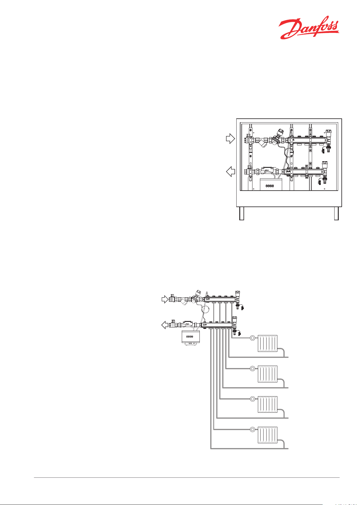
Installation Example
Danfoss pre-fabricated HDU distribution units are
made for distribution and measuring of waterbased heating in 2-pipe horizontal systems.
A HDU is easily mounted on the apartment wall
and connected to the riser. The radiators in the
apartment are connected through the manifold.
The unit design provides a good overview of the
installation, which makes after-service easy.
All Danfoss distribution units are equipped with:
heat meter, for individual measuring of en-
▪
ergy consumption.
dP controller, to ensure hydraulic stability in
▪
the heating system.
HDU multi-port units are wall-mounted and created for parallel radiator distribution. HDU multiport units are available with 4 or 7 manifold
ports, each in two versions with left or right connection.
HDU 4-port
- with left connection
HDU multi-port system
Danfoss Heating Solutions VDIGB102 © Danfoss 08/2012 1
Page 2
Data Sheet Horizontal Distribution Units - HDU Multi-port
Technical Data
Ordering
Max. temperature 90 °C
Max. working pressure in heating system piping before the unit 2 bar
Normal required differential pressure over unit (HDU-SF) 0.26 bar*
Max. differential pressure in a control loop 0.22 bar
Max. static pressure 10 bar (PN10)
Connection to riser (in and out) R ¾"
Connection to manifold (out) ¾"
Power supply (Heat Meter) A-cell battery, 3.6 VDC
*At differential pressure in control loop 10 kPa at
100% AB-PM setting.
HDU-SF Connection Code no.
Horizontal Distribution Unit Single Flat - HDU-SF 4-port left 003L1222
Horizontal Distribution Unit Single Flat - HDU-SF 4-port right 003L1228
Horizontal Distribution Unit Single Flat - HDU-SF 7-port left 003L1225
Horizontal Distribution Unit Single Flat - HDU-SF 7-port right 003L1231
Accessories and Spare Parts Code no.
Manifold port plug (10 pcs.) 003L1246
Capillary tube for AB-PM 003L8152
Filter for strainer 065B8248
Modules for Heat Meter Code no.
M-Bus module 087G6027
Communication
Function
Compression Fittings Data Size Code no.
For PEX tubing
(in accordance with ISO 15875)
For ALUPEX tubing
For steel and copper tubing
Note! Max. flow temperature given by the tube manufacturer must not be exceeded.
L-Bus module (use for external radio) 087G6035
RS232 module 087G6029
RS485 module 087G6032
Analogue output module (4 - 20 mA) 087G6034
Combined module (2 pulse inputs / 1 pulse output) 087G6041
Pulse input module (2 inputs) 087G6037
Pulse output module (2 outputs) 087G6039
16 x 2 mm 013G4156
PN6
G ¾” internal thread
PN10
G ¾” internal thread
PN10
G ¾” internal thread
20 x 2 mm 013G4160
20 x 2.25 mm 013G4093
20 x 2.5 mm 013G4161
16 x 2 mm 013G4186
20 x 2 mm 013G4190
20 x 2.25 mm 013G4093
20 x 2.5 mm 013G4191
16 mm 013G4126
18 mm 013G4128
2 VDIGB102 © Danfoss 08/2012 Danfoss Heating Solutions
Page 3
1
2
3
4
6
7
Data Sheet Horizontal Distribution Units - HDU Multi-port
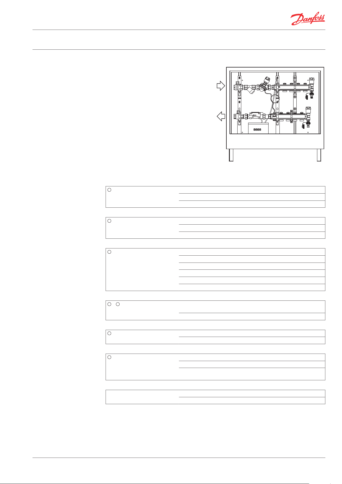
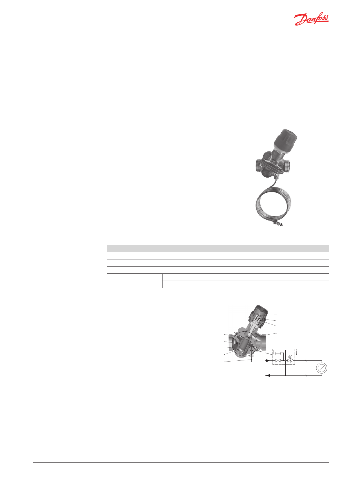
Design
Materials in Contact with
Water
1. Ball valve for in- and outlet connection to the
riser.
2. Strainer to trap dirt, sand etc. from pipe water
(replacement filter available as accessory).
3. AB-PM automatic balancing valve, combines
three functions: differential pressure controller,
control valve with linear characteristic and
flow limiter.
4. Manifold for radiator connection, flow.
5. Manifold for radiator connection, return.
6. Automatic air vent and drainage (both inlet
and outlet has drainage and air vent possibilities).
7. Heat Meter for energy measuring, with 8-digit
LCD.
8. Cabinet (with lockable door).
Shut- off valves Body, tailpiece, ball Brass
Seals PTFE
O-ring EPDM
Strainer Body Brass
Filter Stainless steel
O-ring EPDM
AB-PM valve Body, cone (CV), seat (CV) Brass
Membrane, O-ring, seat (PC) EPDM
Spring, cone (PC), screw Stainless steel
Flat gasket NBR
Sealing agent Dimethacrylate Ester
Capillary tube Copper
& 5 Manifold Inlet adapter, shutter, manifold
Air vent & drainage Body Brass
Heat Meter Body of flow meter Brass
Other parts Assembly nipples Brass
pipe, Euro cone connector
O-rings EPDM
Seals EPDM
Temperature sensors, reflectors Stainless steel
Measuring tube qp 0.6 - 2.5 --> PES
Flat gaskets Aramide fibres, NBR
Brass
qp 3.5 - 60 --> PEEK-GF or PPS-GF
Danfoss Heating Solutions VDIGB102 © Danfoss 08/2012 3
Page 4
ΔP_a
ΔP_a ≥ ΔP_v + ΔP_loop
ΔP_loop
ΔP_loop
ΔP_loop
ΔP_loop
Q [l/h]
ΔP_v
100%
90%
80%
70%
60%
50%
40%
30%
20%
5 6 7
8 9 10
11 12 13 14 15 16 17 18
700
600
500
400
300
200
100
0
Data Sheet Horizontal Distribution Units - HDU Multi-port
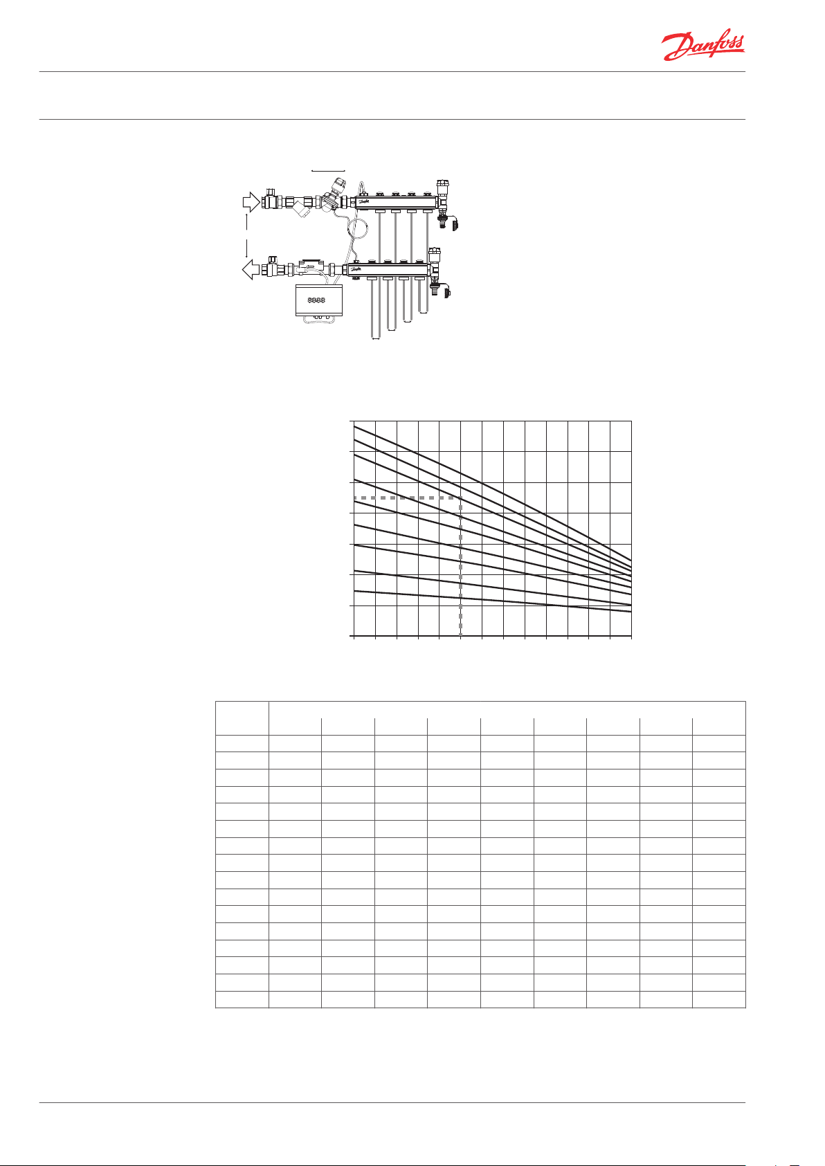
Settings
Q = Needed design flow for the loop.
Δ P_loop = Needed design Δ P for the loop.
Δ P_a = available Δ P.
Δ P_V = min needed Δ P for AB-PM (starting Δ PV) = 16 kPa
Flow l/h
Δ P_loop [kPa]
Δ P_loop
[kPa]
20% 30% 40% 50% 60% 70% 80% 90% 100%
5 142 209 294 360 443 509 591 642 684
6 138 201 284 346 424 484 563 611 655
7 134 193 274 331 405 460 534 580 626
8 129 185 263 316 386 435 505 548 595
9 125 177 252 300 366 410 476 516 564
10 120 168 240 285 346 386 447 484 531
11 115 160 228 269 326 361 418 452 498
12 110 151 215 253 305 337 388 420 464
13 104 142 202 237 284 313 359 388 430
14 99 134 189 221 263 288 329 355 394
15 93 125 175 205 241 264 299 322 357
16 87 116 161 188 219 240 269 289 320
17 81 107 146 172 196 216 239 256 282
18 74 97 131 155 174 192 209 222 243
19 68 88 116 138 150 168 179 189 203
20 61 79 100 120 127 144 148 155 162
Flow [l/h] - average
4 VDIGB102 © Danfoss 08/2012 Danfoss Heating Solutions
Page 5
Data Sheet Horizontal Distribution Units - HDU Multi-port
Example Given:
Design flow trough radiatorsloop: 450 l/h
Pressure drop trough the loop at design flow: 10 kPa
Solution:
Set to 80 %, AB-PM will control differential pressure of 10 kPa when design flow is achieved. It will at any loads including keep it under 22 kPa at zero load, while limiting the
flow to radiator system to 450 l/h.
AB-PM Automatic Balancing Valve
AB-PM is a combined automatic balancing valve. It
features three functions in a compact valve body:
1. Differential pressure controller.
2. Control valve with linear characteristic.
3. Flow limiter.
Benefits:
Reliable heating system resulting in proper
▪
heat distribution even at partial loads and
noise free operation based on stable low Δp
over thermostatic radiator valves even in installation where higher pump head is needed.
Lower heating cost.
▪
Better indoor temperature control • Faster in
▪
simpler installation with less installation space
needed.
Technical data
Nominal diameter DN20
Control valves characteristic Linear
Shut-off leakage rate Acc. to ISO 5208 class A - no visible leakage
CV stroke 2.25 mm
Connection
Ext. thread ISO 228/1 G 1 A
Actuator M 30 x 1.5
Design
1. Spindle.
2. Stuffing box.
3. Pointer.
4. Control valve’s cone.
5. Membrane.
6. Main spring.
7. Hollow cone (pressure controller).
8. Vulcanized seat (pressure controller).
9. Impulse tube.
AB-PM is a combined automatic balancing valve. It is working as Δp controller, flow limiter and zone
controller. Higher pressure acts on the upper side of the control diaphragm (5) while via an impulse
tube (9) lower pressure in the return pipe acts on the lower side of the diaphragm. When available
pressure increases at partial loads, the membrane closes and thus keeps stable Δp inside the controlled loop. Δp controller keeps constant differential pressure on the controlled loop including the control part of AB-PM (similar as if ASV-I would be integrated into ASV-P).
Danfoss Heating Solutions VDIGB102 © Danfoss 08/2012 5
The control part of AB-PM is working as a flow limiter. This enables to set both the design flow as well
as needed Δp. The flow rate is defined by presetting AB-PM, based on pressure demand of the loop.
With actuator mounted on the valve, AB-PM can be used as zone valve. When connected to the room
controller with time programs, functions such as night setback, holiday mode, etc become available.
Page 6

SONOMETER™1100
Heat meter
Made in Germany
3030716
087G6103
Installation: high temp.
S/N: 41598383
qs: 5m3/h
qp: 2.5m3/h
qi: 0.025m3/h
PS/PN: 16
DN20 IP54
Θq: 5...130°C
Θ: 1....180°C
ΔΘ: 3...177K
Pt 500
class 2
E1 / M1
P.-Year 2012
GPM
V
ΔT ΔT
-V
Data Sheet Horizontal Distribution Units - HDU Multi-port
Sonometer 1100 Heat Meter
The SONOMETER™1100 is an ultrasonic static
compact energy meter especially designed for
heating, cooling or combined heating/cooling
application in local and district energy systems.
The SONOMETER™1100 as a compact energy meter consists of the following components:
Ultrasonic flow sensor.
▪
Calculator with integral hardware and soft-
▪
ware for measuring flow rate, temperature
and energy consumption.
Pair of temperature sensors.
▪
Features
Complete dynamic range: ≥ 1 : 1500.
▪
Lithium battery, 230 V AC or 24 V AC mains unit.
▪
Battery lifetime 11 years (16 years optional).
▪
Unique free- beam principle.
▪
Swirl-free flow around reflector.
▪
Lower pressure loss.
▪
Robust stainless steel reflector.
▪
Insensitive to dirt.
▪
Measuring accuracy meets the requirements of EN 1434 ( MID) class 2.
▪
Special features
Remote reading via M-Bus, L-Bus, RS 232, RS 485, Radio or optical interface.
▪
Individual remote reading (Automatic Meter Reading) with add on modules Plug & Play.
▪
2 communication ports (e.g. M-Bus + M-Bus).
▪
Insensitive to presence of magnetite parts in heating water.
▪
Straight parts before and after HDU-SF are not required.
▪
History memory for 24 months.
▪
Extensive diagnostic displays.
▪
IZAR@SET parameterization software on Windows basis guarantees optimum adaptation to the
▪
user’s specific needs.
Software
The IZAR@SET parameterization software on windows basis is a convenient tool for handling the energy meter. The IZAR@SET software is available on web site www.hydrometer.de.
It is used for:
commissioning
▪
reading out measured values
▪
printing out energy meter logs
▪
energy meter configuration
▪
application analysis
▪
print the meter protocol
▪
6 VDIGB102 © Danfoss 08/2012 Danfoss Heating Solutions
Page 7

Data Sheet Horizontal Distribution Units - HDU Multi-port
Technical Data
Temperature sensors Type Pt 500 with 2-wire leads
Sensor current mA Pt 500 peak < 2; rms < 0.012
Measuring cycle T s Mains unit supply: 2 (A-cell battery: 16; D-cell battery: 4)
Input
Supply
voltage
Basic
features
Display
indication
Max. temperature difference
Min. temperature difference
Starting temperature
difference
Absolute temperature
measuring range
Operating voltage
Ambient class EN 1434 class E1 + M1
Protection class IP 54
Type Static energy meter to EN 1434 (MID)
Measuring process Ultrasonic volume measurement
Display LCD, 8-digit
Units MWh - kWh - GJ - Gcal - MBtu - gal - GMP - °C - °F - m³ - m³/h
Total values 99 999 999 - 9999 999.9 - 999 999.99 - 99 999.999
Values displayed Power - energy - flow rate - temperature - volume
Δθmax K 177
Δθmax K 3
Δθmax K 0.125
θ °C 1...180
U
N
3.6 V DC (Lithium-battery) / 230 V AC / 24 V AC
Measuring accuracy to EN 1434 Class 2
Design and Function
The SONOMETER™1100 as a compact energy meter consists of the following components:
Ultrasonic flow sensor.
▪
Calculator with integral hardware and software for measuring flow rate, temperature and ener-
▪
gy consumption.
Optimized pair of temperature sensors.
▪
The calculator contains all the necessary circuits for recording the flow rate and temperature and for
calculating, logging and displaying the data. The energy meter can be conveniently read from a single-line 8-digit display with units and symbols. A push-button provides user-friendly control of the
various display loops.
All failures and faults are recorded automatically and shown on the LC display. To protect the reading data, all the relevant data are saved in a non-volatile memory (EEPROM). This memory saves the
measured values, device parameters and types of error at regular intervals.
Danfoss Heating Solutions VDIGB102 © Danfoss 08/2012 7
Page 8

Data Sheet Horizontal Distribution Units - HDU Multi-port
Ultrasonic flow sensor
The ultrasonic technology of the flow sensor permits very high measuring accuracy and can be used
in the supply or return line. The flow sensor meets the requirements of EN 1434 / class 2.
Supply voltage: Lithium battery 3.6 V DC A-cell (11 years typical lifetime).
Temperature Sensors
Pairs of Pt 500 temperature sensors with 2-wire leads are used.
8 VDIGB102 © Danfoss 08/2012 Danfoss Heating Solutions
Page 9

Data Sheet Horizontal Distribution Units - HDU Multi-port
Interfaces
Optical: ZVEI interface as standard, for communication and testing, M-Bus protocol.
▪
M-Bus: The M-Bus communication module is a serial interface for communication with external
▪
M-Bus control centre. The module contains a 2-pole terminal strip with terminals marked 24, 25,
which are connected to M-Bus control centre. M-Bus protocol to EN 1434-3 standard.
L-Bus: Adapter for external radio module; configurable telegram, according to EN1434-3. Data
reading and parametrization are via two wires with polarity reversal protection. M-Bus protocol.
RS232:The RS232 communication module is a serial interface for communication with external
▪
devices, e.g. PC. The module contains a 3-pole terminal strip with terminals marked 62(Dat),
63(Req) and 64(GND). A special adapter cable is required for connection. (order no. 087H0121).
RS485: The RS485 communication module is a serial interface for communication with external
▪
devices, e.g. PC.
The module contains a 4-pole terminal strip with terminals marked "D+", "D-", "+12V", "-12V".
The module needs an external power supply of 12 V DC ±5 V.
Pulse output: The module contains connections for 2 pulse outputs, , proportional to the flow or
▪
heat consumption. The module contains a 4-pole terminal strip with pulse input 1 marked as
“O1 - |_” and input 2 as “O2 - |_”. External supply: Vcc = 3-30 V DC. Output current < 20 mA with
a residual voltage of < 0.5 V Open collector (drain) Electrically isolated Output 1: f < 4 Hz. Pulse
duration: 125 ms ±10 %. Pulse break: > 125 ms –10 %
Output 1:
▪
Output frequency: f < 4 Hz
▪
Pulse duration: 125 ms ±10 %
▪
Pulse break: > 125 ms –10 %
▪
Output 2:
▪
Output frequency: f < 100 Hz
▪
Pulse duration
▪
Pulse break ~1:1
▪
Volume pulse value is configurablevia IZAR@SET software
▪
Pulse input: Module for two additional pulse counters. The module contains a 4-pole terminal
▪
strip with pulse input 1 marked as “I1 - |_” and input 2 as “I2 - |_”.
Pulse inputs 1 and 2 are programmable for a value of: 1, 2.5, 10, 25, 100, 250, 1000, 2500 litres
▪
per pulse.
Possible units are all the energy units available in the meter, the volume unit m³ or no unit
▪
Input frequency is in the range < 8 Hz. Min. pulse duration 10 ms.
▪
Input resistance 2.2 MΩ.
▪
Terminal voltage 3 V DC.
▪
Data is accumulated separately in registers
▪
Data is readable as IN1 and IN2 in the display and can be transmitted over the communication
▪
modules
Cable length up to 10 m
▪
The combined module is equipped with 2 inputs and 1 output. Combined pulse input / out-
▪
put:The pulse input specification is the same as that of the pulse input module above. The pulse
output specification is the same as pulse output module above, but not electrically isolated.
pulse duration /pulse break ~ 1:1. Configurable via IZAR@SET software.
Analogue output:
▪
The module contains connections for 2 passive analogue outputs, which can be programmed
as desired using the IZAR@SET software. The outputs are marked on the terminal strip as “1”
and “2” with the respective polarity “+” and “–”.
Passive; external power supply: 10…30 V DC
▪
Current loop 4 … 20 mA, where 4 mA = 0 value; 20 mA = programmed max. value
▪
Overload up to 20.5 mA, then fault current
▪
Errors are generated at 3.5 mA or 22.6 mA (programmable)
▪
Output values: power, flow rate, Configurable via IZAR@SET software.
▪
Danfoss Heating Solutions VDIGB102 © Danfoss 08/2012 9
Page 10

Data Sheet Horizontal Distribution Units - HDU Multi-port
Slot 1
Analogue output module (4-20 mA).
▪
Combined module (2 pulse inputs / 1 pulse output).
▪
Pulse input module (2 inputs).
▪
M-Bus module.
▪
L-Bus module (use for external radio).
▪
RS232 module.
▪
RS485 module.
▪
Slot 2
Pulse output module.
▪
Combined module (2 pulse inputs / 1 pulse output).
▪
Pulse input module (2 inputs).
▪
M-Bus module.
▪
L-Bus module (use for external radio).
▪
RS232 module.
▪
RS485 module.
▪
Event Memory
Events such as changes and faults are stored in a nonvolatile memory with a capacity of up to 127
entries.
The following events are recorded:
Checksum error.
▪
Temperature measurement error.
▪
Ultrasonic operating time measurement errors.
▪
Start and end of test mode.
▪
Changing of the main configuration.
▪
10 VDIGB102 © Danfoss 08/2012 Danfoss Heating Solutions
Page 11

Data Sheet Horizontal Distribution Units - HDU Multi-port
Monthly Memory
The SONOMETER™1100 has a history memory of 24 months. The following values are stored in the
EEPROM on the programmable interval (daily, weekly, monthly):
Date/ Time.
▪
Cumulated energy.
▪
Tariff energy 1.
▪
Tariff energy 2.
▪
Tariff definition 1.
▪
Tariff definition 2.
▪
Cumulated volume.
▪
Error hour counter.
▪
Value of max. flow.
▪
Time max. flow.
▪
Date max. flow.
▪
Value of max. power.
▪
Time max. power.
▪
Date max. power.
▪
Pulse input counter 1.
▪
Pulse input counter 2.
▪
Pulse 1 definition.
▪
Pulse 2 definition.
▪
Operating days.
▪
Max. forward temperature.
▪
Time max. forward temperature.
▪
Date max. forward temperature.
▪
Max. return temperature.
▪
Time max. return temperature.
▪
Date max. return temperature.
▪
Log Memory
The large two log memory blocks are used to store consumption values. The storage frequency can
be selected from various storage intervals (1, 2, 3, 4, 5, 6, 10, 12, 15, 20, 30, 60 minutes or the default
setting of 24 hours, Day in the month, Day of the week, (1024 seconds), 15th or end of month).
The data saved in the log memory can be used for the following analyses:
Reading the calculator on a certain day. Example: If the day for reading is 01.10, the calculator
▪
reading is displayed for the period from 01.10 of the previous year to 30.09 of the current year.
Comparison of the last consumption period with the preceding period.
▪
Extract of possible log memory settings
Memory
block
area 1 1 hour Error status, overload time temperature, overload
area 2 24 hours 16 byte 299 299 days
area 1 1 hour 8 byte 1113 46 days
area 2 24 hours 8 byte 599 599 days
Storage
interval
Values Date block size
example
16 byte 556 23 days
time flow rate, supply temperature, return temperature, date and time, energy, tariff energy 1, tariff energy 2, tariff definition 1, tariff definition 2, volume, error day counter
Number of
data records
Recording
period
Max. Actual Values Memories
The calculator creates maximum values for power, flow rate and temperatures based on consumption time, which are stored in the EEPROM. The integration intervals are adjustable to 6, 15, 30 or 60
minutes, 24 hours (and 1024 seconds). Default setting is 60 minutes.
Danfoss Heating Solutions VDIGB102 © Danfoss 08/2012 11
Page 12

Data Sheet Horizontal Distribution Units - HDU Multi-port
Tariff Function
The calculator offers four optional tariff memories for monitoring plant load states for limit tariffs.
Extensive tariff conditions make it possible to adapt the energy meter individually to the required
customer-specific applications.
The following limit types are possible (this example applies to the display with 3 decimal places):
Type LIMIT LIMIT resolution
∆T 1 ... 255 °C 1 °C
TR T
F
P 1 ... 255 °C 1 kW
Q 100 ... 25 500 l/h 100 l/h
Z 15 minutes
Display Control
The readings are displayed on the calculator by a 8-digit LCD with units and symbols.
Loop Structure
The SONOMETER™1100 display has six loops. Some display windows consist of two (to maximum
seven) displays that are shown alternately at 4-second intervals. Some pictures in loops or a complete loop can be deactivated separately.
For quick visual guidance, the loops in the display are numbered from 1 to 6.
The main loop with the current data, e.g. for energy, volume and flow rate is programmed as default
setting.
1 ... 255 °C 1 °C
Overview of Loops
12 VDIGB102 © Danfoss 08/2012 Danfoss Heating Solutions
Page 13

Data Sheet Horizontal Distribution Units - HDU Multi-port
Informative Displays
Loop Sequence Window 1 Window 2
"1"
Main loop
Loop Sequence Window 1 Window 2 Window 3
"2"
Accounting date loop
1.1 Accumulated energy
1.2 Volume
1.3 Flow
1.4 Power
1.5 Forward temperature Return temperature
1.6 Difference temperature
1.7 Operating days
1.9 Error status
1.10 Display test
2.1 Accounting date 1 (date 1) Accounting date 1 energy 'Accd 1A'
2.2 Next accounting date 1 (date 1) Next accounting date 1 energy 'Accd 1L'
2.3 Previous accounting date 1 (date 1) Previous accounting date 1 energy 'Accd 1'
2.4 'Accd 1' Date of next accounting date 1
2.5 Accounting date 2 (date 2) Accounting date 2 energy 'Accd 2A'
2.6 Next accounting date 2 (date 2) Next accounting date 2 energy 'Accd 2L'
2.7 Previous accounting date 2 (date 2) Previous accounting date 2 energy 'Accd 2'
2.8 'Accd 2' Date of next accounting date 2
Loop Sequence Window 1 Window 2
"3"
Info loop
Loop Se-
"4"
Pulse input loop
Loop Se-
"5"
Tariff loop
Loop Se-
"6"
Monthly value loop
3.1 Current date
3.2 'SEC_Adr' Secondary address
3.3 'Pri_Adr 1' Primary address 1
3.4 'Pri_Adr 2' Primary address 2
3.5 Installation position
3.6 'Port 1' No. of the mounted module at port 1
3.7 'Port 2' No. of the mounted module at port 2
3.8 Status integrated radio (Sequence will be shown only in meters with
3.9 No. of error hours
3.10 'F01-001' (software version) Checksum
quence
4.1 'In1' Accumulated values pulse input 1 'PPI' pulse value 1
4.2 'In2' Accumulated values pulse input 2 'PPI' pulse value 2
Window 1 Window 2 Window 3 Window 4 Window 5 Window 6 Window 7
quen
ce
Window 1 Window 2 Window 3 Window 4 Window 5 Window 6
quen
ce
6.1 'Date last
month'
6.2 'Date month -1'date month -1Energy Tariff 1 Tariff 2 Volume
Window 1 Window 2 Window 3
The tariff loop is switched off as a standard at the heat meter or meter for cooling.
Accumulated
energy
Energy Tariff 1 Tariff 2 Volume
integrated radio)
6.3 'Date month -2'date month -2Energy Tariff 1 Tariff 2 Volume
...
... ...
6.24 'Date month -
date month -23Energy Tariff 1 Tariff 2 Volume
23'
Danfoss Heating Solutions VDIGB102 © Danfoss 08/2012 13
Page 14

480
380
62
95
51
49
23
213
113 200
266
50
25
125
B
A
C
D
665
685
120
Data Sheet Horizontal Distribution Units - HDU Multi-port
Loop review
A push-button mounted on the front of the calculator is used to switch to the various displays. The
button can be pressed for a short or long time. A short press of the button ( < 3 seconds) switches to
the next display within a loop and a long press ( > 3 seconds) switches to the next display loop. The
“Energy” window (sequence 1.1) in the main loop is the basic display.
The calculator switches automatically to power save mode if the button is not pressed for approx. 4
minutes and returns to the basic display when the button is pressed again. The loop settings can be
programmed to suit the customer’s individual requirements using the IZAR@SET software.
Dimensions
4-port 7-port
A 480 mm 630 mm
B 265 mm 365 mm
C 670 mm 820 mm
D 715 mm 865 mm
14 VDIGB102 © Danfoss 08/2012 Danfoss Heating Solutions
Page 15

Data Sheet Horizontal Distribution Units - HDU Multi-port
Danfoss Heating Solutions VDIGB102 © Danfoss 08/2012 15
Page 16

Data Sheet Horizontal Distribution Units - HDU Multi-port
Danfoss A/S
Heating Solutions
Haarupvaenget 11
8600 Silkeborg
Denmark
Phone:+45 7488 8000
Fax: +45 7488 8100
Email: heating.solutions@danfoss.com
www.heating.danfoss.com
Danfoss can accept no responsibility for possible errors in catalogues, brochures and other printed material. Danfoss reserves the right to alter its products without notice. This also applies to products
already on order provided that such alterations can be made without subsequential changes being necessary in specifications already agreed. All trademarks in this material are property of the respective
companies. Danfoss Heating Solutions and the Danfoss Heating Solutions logotype are trademarks of Danfoss A/S. All rights reserved.
16 VDIGB102 © Danfoss 08/2012 Danfoss Heating Solutions
 Loading...