

Page 1
MAKING MODERN LIVING POSSIBLE
Design Guide
VLT® Refrigeration Drive FC 103
1.1–90 kW
vlt-drives.danfoss.com
Page 2

Page 3

Contents Design Guide
Contents
1 Introduction
1.1 Purpose of the Design Guide
1.2 Organisation
1.3 Additional Resources
1.4 Abbreviations, Symbols and Conventions
1.5 Safety Symbols
1.6 Denitions
1.7 Document and Software Version
1.8 Approvals and Certications
1.8.1 CE Mark 10
1.8.1.1 Low Voltage Directive 10
1.8.1.2 EMC Directive 10
1.8.1.3 Machinery Directive 11
1.8.1.4 ErP Directive 11
1.8.2 C-tick Compliance 11
1.8.3 UL Compliance 11
1.8.4 Marine Compliance (ADN) 11
7
7
7
7
8
9
9
10
10
1.8.5 Export Control Regulations 12
1.9 Safety
1.9.1 General Safety Principles 12
2 Product Overview
2.1 Introduction
2.2 Description of Operation
2.3 Sequence of Operation
2.3.1 Rectier Section 18
2.3.2 Intermediate Section 18
2.3.3 Inverter Section 18
2.4 Control Structures
2.4.1 Control Structure Open Loop 19
2.4.2 Control Structure Closed Loop 19
2.4.3 Local (Hand On) and Remote (Auto On) Control 20
2.4.4 Reference Handling 21
2.4.5 Feedback Handling 23
2.5 Automated Operational Functions
12
14
14
17
18
19
24
2.5.1 Short-circuit Protection 24
2.5.2 Overvoltage Protection 24
2.5.3 Missing Motor Phase Detection 24
2.5.4 Mains Phase Imbalance Detection 25
MG16G202 Danfoss A/S © 08/2015 All rights reserved. 1
Page 4

Contents
VLT® Refrigeration Drive FC 103
2.5.5 Switching on the Output 25
2.5.6 Overload Protection 25
2.5.7 Automatic Derating 25
2.5.8 Automatic Energy Optimisation 25
2.5.9 Automatic Switching Frequency Modulation 25
2.5.10 Automatic Derating for High Switching Frequency 26
2.5.11 Automatic Derating for Overtemperature 26
2.5.12 Auto Ramping 26
2.5.13 Current Limit Circuit 26
2.5.14 Power Fluctuation Performance 26
2.5.15 Motor Soft Start 26
2.5.16 Resonance Damping 26
2.5.17 Temperature-controlled Fans 26
2.5.18 EMC Compliance 26
2.5.19 Current Measurement on All Three Motor Phases 27
2.5.20 Galvanic Isolation of Control Terminals 27
2.6 Custom Application Functions
2.6.1 Automatic Motor Adaptation 27
2.6.2 Motor Thermal Protection 27
2.6.3 Mains Drop-out 27
2.6.4 Built-in PID Controllers 28
2.6.5 Automatic Restart 28
2.6.6 Flying Start 28
2.6.7 Full Torque at Reduced Speed 28
2.6.8 Frequency Bypass 28
2.6.9 Motor Preheat 28
2.6.10 Four Programmable Set-ups 29
2.6.11 DC Braking 29
2.6.12 Sleep Mode 29
2.6.13 Run Permissive 29
2.6.14 Smart Logic Control (SLC) 29
2.6.15 Safe Torque O Function 30
27
2.7 Fault, Warning and Alarm Functions
31
2.7.1 Operation at Overtemperature 31
2.7.2 High and Low Reference Warning 31
2.7.3 High and Low Feedback Warning 31
2.7.4 Phase Imbalance or Phase Loss 31
2.7.5 High Frequency Warning 31
2.7.6 Low Frequency Warning 31
2.7.7 High Current Warning 31
2 Danfoss A/S © 08/2015 All rights reserved. MG16G202
Page 5

Contents Design Guide
2.7.8 Low Current Warning 31
2.7.9 No Load/Broken Belt Warning 31
2.7.10 Lost Serial Interface 32
2.8 User Interfaces and Programming
2.8.1 Local Control Panel 32
2.8.2 PC Software 33
2.8.2.1 MCT 10 Set-up Software 33
2.8.2.2 VLT® Harmonics Calculation Software MCT 31 33
2.8.2.3 Harmonic Calculation Software (HCS) 33
2.9 Maintenance
2.9.1 Storage 34
3 System Integration
3.1 Ambient Operating Conditions
3.1.1 Humidity 35
3.1.2 Temperature 36
3.1.3 Cooling 36
3.1.4 Motor-generated Overvoltage 37
3.1.5 Acoustic Noise 37
3.1.6 Vibration and Shock 37
3.1.7 Aggressive Atmospheres 37
32
34
35
35
3.1.8 IP Rating Denitions 38
3.1.9 Radio Frequency Interference 39
3.1.10 PELV and Galvanic Isolation Compliance 39
3.2 EMC, Harmonics, and Ground Leakage Protection
3.2.1 General Aspects of EMC Emissions 40
3.2.2 EMC Test Results (Emission) 42
3.2.3 Emission Requirements 43
3.2.4 Immunity Requirements 43
3.2.5 Motor Insulation 44
3.2.6 Motor Bearing Currents 44
3.2.7 Harmonics 45
3.2.8 Ground Leakage Current 47
3.3 Energy Eciency
3.3.1 IE and IES Classes 50
3.3.2 Power Loss Data and Eciency Data 50
3.3.3 Losses and Eciency of a Motor 51
3.3.4 Losses and Eciency of a Power Drive System 51
40
49
3.4 Mains Integration
3.4.1 Mains Congurations and EMC Eects 51
MG16G202 Danfoss A/S © 08/2015 All rights reserved. 3
51
Page 6

Contents
VLT® Refrigeration Drive FC 103
3.4.2 Low-frequency Mains Interference 52
3.4.3 Analysing Mains Interference 53
3.4.4 Options for Reducing Mains Interference 53
3.4.5 Radio Frequency Interference 53
3.4.6 Classication of the Operating Site 53
3.4.7 Use with Isolated Input Source 54
3.4.8 Power Factor Correction 54
3.4.9 Input Power Delay 54
3.4.10 Mains Transients 54
3.4.11 Operation with a Standby Generator 54
3.5 Motor Integration
3.5.1 Motor Selection Considerations 55
3.5.2 Sine-wave and dU/dt Filters 55
3.5.3 Proper Motor Grounding 55
3.5.4 Motor Cables 55
3.5.5 Motor Cable Shielding 56
3.5.6 Connection of Multiple Motors 56
3.5.7 Motor Thermal Protection 57
3.5.8 Output Contactor 58
3.5.9 Energy Eciency 58
3.6 Additional Inputs and Outputs
3.6.1 Wiring Schematic 59
3.6.2 Relay Connections 60
3.6.3 EMC-compliant Electrical Connection 61
3.7 Mechanical Planning
3.7.1 Clearance 62
3.7.2 Wall Mounting 63
55
59
62
3.7.3 Access 63
3.8 Options and Accessories
3.8.1 Communication Options 66
3.8.2 Input/Output, Feedback, and Safety Options 66
3.8.3 Sine-wave Filters 66
3.8.4 dU/dt Filters 66
3.8.5 Harmonic Filters 66
3.8.6 IP21/NEMA Type 1 Enclosure Kit 67
3.8.7 Common-mode Filters 69
3.8.8 Remote Mounting Kit for LCP 69
3.8.9 Mounting Bracket for Enclosure Sizes A5, B1, B2, C1, and C2 70
3.9 Serial Interface RS485
3.9.1 Overview 71
4 Danfoss A/S © 08/2015 All rights reserved. MG16G202
63
71
Page 7

Contents Design Guide
3.9.2 Network Connection 72
3.9.3 RS485 Bus Termination 72
3.9.4 EMC Precautions 73
3.9.5 FC Protocol Overview 73
3.9.6 Network Conguration 73
3.9.7 FC Protocol Message Framing Structure 73
3.9.8 FC Protocol Examples 77
3.9.9 Modbus RTU Protocol 78
3.9.10 Modbus RTU Message Framing Structure 79
3.9.11 Access to Parameters 82
3.9.12 FC Drive Control Prole 83
3.10 System Design Checklist
4 Application Examples
4.1 Application Examples
4.2 Selected Application Features
4.2.1 SmartStart 91
4.2.2 Start/Stop 92
4.2.3 Pulse Start/Stop 92
4.2.4 Potentiometer Reference 93
4.3 Application Set-up Examples
5 Special Conditions
5.1 Derating
5.2 Manual Derating
5.3 Derating for Long Motor Cables or Cables with Larger Cross-section
5.4 Derating for Ambient Temperature
6 Type Code and Selection
89
91
91
91
93
99
99
99
99
100
104
6.1 Ordering
6.1.1 Introduction 104
6.1.2 Type Code 104
6.2 Options, Accessories, and Spare Parts
6.2.1 Ordering Numbers: Options and Accessories 105
6.2.2 Ordering Numbers: Harmonic Filters 107
6.2.3 Ordering Numbers: Sine-wave Filter Modules, 200–480 V AC 107
6.2.4 Ordering Numbers: Sine-wave Filter Modules, 525-600/690 V AC 108
6.2.5 Harmonic Filters 109
6.2.6 Sine-wave Filters 111
6.2.7 dU/dt Filters 113
6.2.8 Common Mode Filters 114
MG16G202 Danfoss A/S © 08/2015 All rights reserved. 5
104
105
Page 8

Contents
VLT® Refrigeration Drive FC 103
7 Specications
7.1 Electrical Data
7.1.1 Mains Supply 3x200–240 V AC 115
7.1.2 Mains Supply 3x380–480 V AC 117
7.1.3 Mains Supply 3x525–600 V AC 119
7.2 Mains Supply
7.3 Motor Output and Motor Data
7.4 Ambient Conditions
7.5 Cable Specications
7.6 Control Input/Output and Control Data
7.7 Connection Tightening Torque
7.8 Fuses and Circuit Breakers
7.9 Power Ratings, Weight, and Dimensions
7.10 dU/dt Testing
7.11 Acoustic Noise Ratings
7.12 Selected Options
7.12.1 VLT® General Purpose I/O Module MCB 101 135
115
115
121
121
122
122
123
126
127
132
133
135
135
7.12.2 VLT® Relay Card MCB 105 136
7.12.3 VLT® Extended Relay Card MCB 113 138
8 Appendix - Selected Drawings
8.1 Mains Connection Drawings
8.2 Motor Connection Drawings
8.3 Relay Terminal Drawings
8.4 Cable Entry Holes
Index
140
140
143
145
146
151
6 Danfoss A/S © 08/2015 All rights reserved. MG16G202
Page 9

Introduction Design Guide
1 Introduction
1.1 Purpose of the Design Guide
This design guide for VLT® Refrigeration Drive FC 103
frequency converters is intended for:
Project and systems engineers.
•
Design consultants.
•
Application and product specialists.
•
The design guide provides technical information to
understand the capabilities of the frequency converter for
integration into motor control and monitoring systems.
The purpose of the design guide is to provide design
considerations and planning data for integration of the
frequency converter into a system. The design guide caters
for selection of frequency converters and options for a
diversity of applications and installations.
Reviewing the detailed product information in the design
stage enables developing a well-conceived system with
optimal functionality and
VLT® is a registered trademark.
Organisation
1.2
Chapter 1 Introduction: The general purpose of the design
guide and compliance with international directives.
Chapter 2 Product Overview: The internal structure and
functionality of the frequency converter and operational
features.
Chapter 3 System Integration: Environmental conditions;
EMC, harmonics, and ground leakage; mains input; motors
and motor connections; other connections; mechanical
planning; and descriptions of options and accessories
available.
Chapter 4 Application Examples: Samples of product
applications and guidelines for use.
eciency.
Chapter 8 Appendix - Selected Drawings: A compilation of
graphics illustrating:
Mains and motor connections
•
Relay terminals
•
Cable entries
•
1.3 Additional Resources
Resources available to understand advanced operation of
the frequency converter, programming, and directives
compliance:
The VLT® Refrigeration Drive FC 103 Operating
•
Instructions (referenced as operating instructions in
this manual) provide detailed information for the
installation and start-up of the frequency
converter.
The VLT® Refrigeration Drive FC 103 Design Guide
•
provides information required for design and
planning for integration of the frequency
converter into a system.
®
The VLT
•
Guide (referenced as programming guide in this
manual) provides greater detail about how to
work with parameters and many application
examples.
The VLT® Safe Torque O Operating Instructions
•
describe how to use Danfoss frequency
converters in functional safety applications. This
manual is supplied with the frequency converter
when the STO option is present.
Supplemental publications and manuals are available for
download from vlt-drives.danfoss.com/Products/Detail/
Technical-Documents.
Refrigeration Drive FC 103 Programming
NOTICE
Optional equipment is available that may change some
of the information described in these publications. Be
sure to see the instructions supplied with the options for
specic requirements.
1 1
Chapter 5 Special Conditions: Details on unusual operational
environments.
Chapter 6 Type Code and Selection: Procedures for ordering
equipment and options to meet the intended use of the
system.
Chapter 7
table and graphics format.
MG16G202 Danfoss A/S © 08/2015 All rights reserved. 7
Specications: A compilation of technical data in
Contact a Danfoss supplier or visit www.danfoss.com for
more information.
Page 10
Introduction
VLT® Refrigeration Drive FC 103
11
1.4 Abbreviations, Symbols and
Conventions
60° AVM 60° asynchronous vector modulation
A Ampere/AMP
AC Alternating current
AD Air discharge
AEO Automatic energy optimisation
AI Analog input
AMA Automatic motor adaptation
AWG American wire gauge
°C
CD Constant discharge
CDM Complete drive module: the frequency converter,
CM Common mode
CT Constant torque
DC Direct current
DI Digital input
DM Dierential mode
D-TYPE Drive dependent
EMC Electromagnetic compatibility
EMF Electromotive force
ETR Electronic thermal relay
f
JOG
f
M
f
MAX
f
MIN
f
M,N
FC Frequency converter
g Gramme
Hiperface®Hiperface® is a registered trademark by Stegmann
HO High overload
hp Horse power
HTL HTL encoder (10–30 V) pulses - High-voltage
Hz Hertz
I
INV
I
LIM
I
M,N
I
VLT,MAX
I
VLT,N
kHz Kilohertz
LCP Local control panel
lsb Least signicant bit
m Meter
Degrees celsius
feeding section and auxiliaries
Motor frequency when jog function is activated.
Motor frequency
Maximum output frequency, the frequency
converter applies on its output.
Minimum motor frequency from the frequency
converter
Nominal motor frequency
transistor logic
Rated inverter output current
Current limit
Nominal motor current
Maximum output current
Rated output current supplied by the frequency
converter
ms Millisecond
msb Most signicant bit
η
VLT
Eciency of the frequency converter dened as
ratio between power output and power input.
nF Capacitance in nano Farad
NLCP Numerical local control panel
Nm Newton meter
NO Normal overload
n
s
Online/
Oine
Synchronous motor speed
Changes to online parameters are activated
immediately after the data value is changed.
Parameters
P
br,cont.
Rated power of the brake resistor (average power
during continuous braking).
PCB Printed circuit board
PCD Process data
PDS Power drive system: a CDM and a motor
PELV Protective extra low voltage
P
m
Frequency converter nominal output power as
high overload (HO).
P
M,N
Nominal motor power
PM motor Permanent magnet motor
Process PID PID (Proportional Integrated Dierential) regulator
that maintains the speed, pressure, temperature,
and so on.
R
br,nom
Nominal resistor value that ensures a brake power
on the motor shaft of 150/160% for 1 minute
RCD Residual current device
Regen Regenerative terminals
R
min
Minimum permissible brake resistor value by
frequency converter
RMS Root mean square
RPM Revolutions per minute
R
rec
Recommended brake resistor resistance of
Danfoss brake resistors
s Second
SFAVM Stator ux-oriented asynchronous vector
modulation
STW Status word
SMPS Switch mode power supply
THD Total harmonic distortion
T
LIM
Torque limit
TTL TTL encoder (5 V) pulses - transistor transistor
logic
U
M,N
Nominal motor voltage
V Volts
VT Variable torque
VVC+
Voltage vector control plus
Table 1.1 Abbreviations
mA Milliampere
MCM Mille circular mil
MCT Motion control tool
mH Inductance in milli Henry
mm Millimeter
8 Danfoss A/S © 08/2015 All rights reserved. MG16G202
Page 11
Introduction Design Guide
Conventions
Numbered lists indicate procedures.
Bullet lists indicate other information and description of
illustrations.
Italicised text indicates:
Cross reference.
•
Link.
•
Footnote.
•
Parameter name, parameter group name,
•
parameter option.
All dimensions are in mm (inch).
* indicates a default setting of a parameter.
1.5 Safety Symbols
The following symbols are used in this manual:
WARNING
Indicates a potentially hazardous situation that could
result in death or serious injury.
CAUTION
Indicates a potentially hazardous situation that could
result in minor or moderate injury. It can also be used to
alert against unsafe practices.
NOTICE
Indicates important information, including situations that
can result in damage to equipment or property.
1.6 Denitions
Coast
The motor shaft is in free mode. No torque on the motor.
CT characteristics
Constant torque characteristics used for all applications
such as:
Conveyor belts.
•
Displacement pumps.
•
Cranes.
•
Initialising
If initialising is carried out (parameter 14-22 Operation
Mode), the frequency converter returns to the default
setting.
Intermittent duty cycle
An intermittent duty rating refers to a sequence of duty
cycles. Each cycle consists of an on-load and an
period. The operation can be either periodic duty or nonperiodic duty.
o-load
Power factor
The true power factor (lambda) considers all the
harmonics. The true power factor is always smaller than
the power factor (cosphi) that only considers the 1st
harmonics of current and voltage.
cosϕ =
Cosphi is also known as displacement power factor.
Both lambda and cosphi are stated for Danfoss VLT
frequency converters in chapter 7.2 Mains Supply.
The power factor indicates to which extent the frequency
converter imposes a load on the mains supply.
The lower the power factor, the higher the I
same kW performance.
In addition, a high power factor indicates that the
harmonic currents are low.
All Danfoss frequency converters have built-in DC coils in
the DC link. The coils ensure a high power factor and
reduce the THDi on the main supply.
Set-up
Save parameter settings in 4 set-ups. Change between the
4 parameter set-ups and edit 1 set-up while another set-up
is active.
Slip compensation
The frequency converter compensates for the motor slip by
giving the frequency a supplement that follows the
measured motor load, keeping the motor speed almost
constant.
Smart logic control (SLC)
The SLC is a sequence of
when the associated user-dened events are evaluated as
true by the SLC. (Parameter group 13-** Smart Logic).
FC standard bus
Includes RS485 bus with FC protocol or MC protocol. See
parameter 8-30 Protocol.
Thermistor
A temperature-dependent resistor placed where the
temperature is to be monitored (frequency converter or
motor).
Trip
A state entered in fault situations, such as when the
frequency converter is subject to an overtemperature or
when it protects the motor, process, or mechanism. Restart
is prevented until the cause of the fault has disappeared
and the trip state is cancelled. Cancel the trip state by:
Do not use trip for personal safety.
P kW
P kVA
Activating reset, or
•
Programming the frequency converter to reset
•
automatically
UλxIλxcosϕ
=
UλxIλ
®
for the
RMS
user-dened actions executed
1 1
MG16G202 Danfoss A/S © 08/2015 All rights reserved. 9
Page 12
Introduction
VLT® Refrigeration Drive FC 103
11
Trip lock
A state entered in fault situations when the frequency
converter is protecting itself and requires physical
intervention, for example if the frequency converter is
subject to a short circuit on the output. A locked trip can
only be cancelled by cutting o mains, removing the cause
of the fault, and reconnecting the frequency converter.
Restart is prevented until the trip state is cancelled by
activating reset or, in some cases, by being programmed to
reset automatically. Do not use trip for personal safety.
VT characteristics
Variable torque characteristics for pumps and fans.
1.7 Document and Software Version
This manual is regularly reviewed and updated. All
suggestions for improvement are welcome.
Table 1.2 shows the document version and the
corresponding software version.
Edition Remarks Software version
MG16G2xx Replaces MG16G1xx 1.4x
Table 1.2 Document and Software Version
Approvals and Certications
1.8
Frequency converters are designed in compliance with the
directives described in this section.
NOTICE
Frequency converters with an integrated safety function
must comply with the machinery directive.
EU Directive Version
Low Voltage Directive 2014/35/EU
EMC Directive 2014/30/EU
Machinery Directive
ErP Directive 2009/125/EC
ATEX Directive 2014/34/EU
RoHS Directive 2002/95/EC
Table 1.3 EU Directives Applicable to Frequency Converters
1) Machinery Directive conformance is only required for frequency
converters with an integrated safety function.
Declarations of conformity are available on request.
1)
1.8.1.1 Low Voltage Directive
The Low Voltage Directive applies to all electrical
equipment in the 50–1000 V AC and the 75–1600 V DC
voltage ranges.
The aim of the directive is to ensure personal safety and
avoid property damage, when operating electrical
equipment that is installed, maintained, and used as
intended.
2014/32/EU
1.8.1.2 EMC Directive
For more information on approvals and certicates, go to
the download area at vlt-marine.danfoss.com/support/type-
approval-certicates/.
1.8.1 CE Mark
Illustration 1.1 CE
The CE mark (Communauté Européenne) indicates that the
product manufacturer conforms to all applicable EU
directives. The EU directives applicable to the design and
manufacture of frequency converters are listed in Table 1.3.
The purpose of the EMC (electromagnetic compatibility)
Directive is to reduce electromagnetic interference and
enhance immunity of electrical equipment and installations. The basic protection requirement of the EMC
Directive is that devices that generate electromagnetic
interference (EMI), or whose operation could be aected
by EMI, must be designed to limit the generation of
electromagnetic interference. The devices must have a
suitable degree of immunity to EMI when properly
installed, maintained, and used as intended.
Electrical equipment devices used alone or as part of a
system must bear the CE mark. Systems do not require the
CE mark, but must comply with the basic protection
requirements of the EMC Directive.
NOTICE
The CE mark does not regulate the quality of the
product. Technical specications cannot be deduced from
the CE mark.
10 Danfoss A/S © 08/2015 All rights reserved. MG16G202
Page 13

Introduction Design Guide
1.8.1.3 Machinery Directive
The aim of the Machinery Directive is to ensure personal
safety and avoid property damage for mechanical
equipment used in its intended application. The Machinery
Directive applies to a machine consisting of an aggregate
of interconnected components or devices of which at least
1 is capable of mechanical movement.
Frequency converters with an integrated safety function
must comply with the Machinery Directive. Frequency
converters without a safety function do not fall under the
Machinery Directive. If a frequency converter is integrated
into a machinery system, Danfoss can provide information
on safety aspects relating to the frequency converter.
When frequency converters are used in machines with at
least 1 moving part, the machine manufacturer must
provide a declaration stating compliance with all relevant
statutes and safety measures.
1.8.1.4 ErP Directive
The ErP Directive is the European Ecodesign Directive for
energy-related products. The directive sets ecodesign
requirements for energy-related products, including
frequency converters. The aim of the directive is to
increase energy eciency and the level of protection of
the environment, while increasing the security of the
energy supply. Environmental impact of energy-related
products includes energy consumption throughout the
entire product life cycle.
1.8.2 C-tick Compliance
Illustration 1.2 C-tick
1.8.3 UL Compliance
UL Listed
Illustration 1.3 UL
NOTICE
525–690 V frequency converters are not certied for UL.
The frequency converter complies with UL 508C thermal
memory retention requirements. For more information,
refer to chapter 2.6.2 Motor Thermal Protection.
1.8.4 Marine Compliance (ADN)
Units with ingress protection rating IP55 (NEMA 12) or
higher prevent spark formation, and are classied as
limited explosion risk electrical apparatus in accordance
with the European Agreement concerning International
Carriage of Dangerous Goods by Inland Waterways (ADN).
For units with ingress protection rating IP20/Chassis, IP21/
NEMA 1, or IP54, prevent risk of spark formation as follows:
Do not install a mains switch.
•
Ensure that parameter 14-50 RFI Filter is set to [1]
•
On.
Remove all relay plugs marked RELAY. See
•
Illustration 1.4.
Check which relay options are installed, if any.
•
The only permitted relay option is VLT® Extended
Relay Card MCB 113.
Go to vlt-marine.danfoss.com/support/type-approval-certif-
icates/ for additional marine approvals information.
1 1
The C-tick label indicates compliance with the applicable
technical standards for Electromagnetic Compatibility
(EMC). C-tick compliance is required for placing electrical
and electronic devices on the market in Australia and New
Zealand.
The C-tick regulatory is about conducted and radiated
emission. For frequency converters, apply the emission
limits specied in EN/IEC 61800-3.
A declaration of conformity can be provided on request.
MG16G202 Danfoss A/S © 08/2015 All rights reserved. 11
Page 14
1
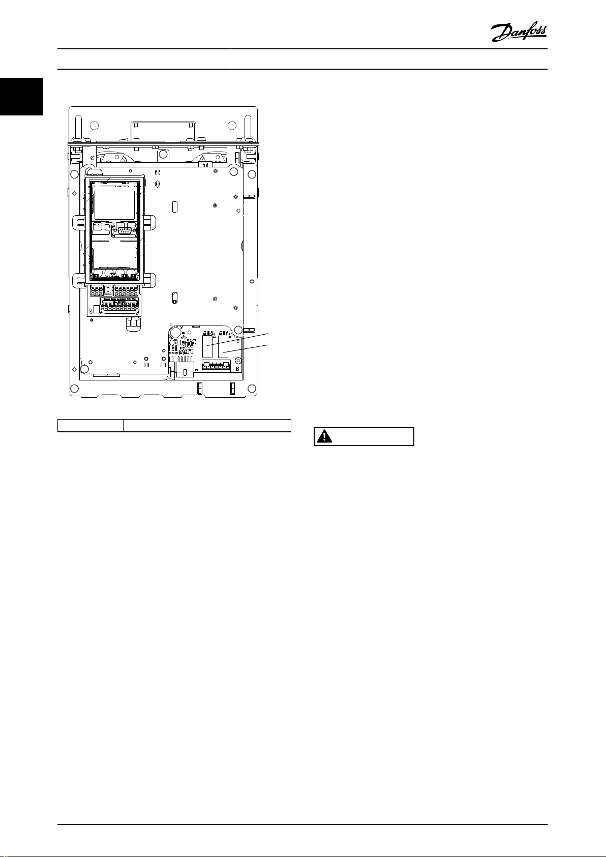
2
130BD832.10
Introduction
VLT® Refrigeration Drive FC 103
11
1.9
Safety
1.9.1 General Safety Principles
If handled improperly, frequency converters have the
potential for fatal injury as they contain high-voltage
components. Only
operate the equipment. Do not attempt repair work
without rst removing power from the frequency converter
and waiting the designated amount of time for stored
electrical energy to dissipate.
Strict adherence to safety precautions and notices is
mandatory for safe operation of the frequency converter.
Correct and reliable transport, storage, installation,
operation, and maintenance are required for the troublefree and safe operation of the frequency converter. Only
qualied personnel are allowed to install and operate this
equipment.
Qualied personnel are dened as trained sta, who are
authorised to install, commission, and maintain equipment,
systems, and circuits in accordance with pertinent laws and
regulations. Additionally, the qualied personnel must be
familiar with the instructions and safety measures
described in these operating instructions.
1, 2 Relay plugs
qualied personnel should install and
WARNING
Illustration 1.4 Location of Relay Plugs
Manufacturer declaration is available on request.
1.8.5 Export Control Regulations
Frequency converters can be subject to regional and/or
national export control regulations.
HIGH VOLTAGE
Frequency converters contain high voltage when
connected to AC mains input, DC supply, or load sharing.
Failure to perform installation, start-up, and maintenance
by qualied personnel can result in death or serious
injury.
Only qualied personnel must perform instal-
•
lation, start-up, and maintenance.
The frequency converters that are subject to export control
regulations are classied by an ECCN number.
The ECCN number is provided in the documents
accompanying the frequency converter.
In case of re-export, it is the responsibility of the exporter
to ensure compliance with the relevant export control
regulations.
12 Danfoss A/S © 08/2015 All rights reserved. MG16G202
Page 15
Introduction Design Guide
WARNING
UNINTENDED START
When the frequency converter is connected to AC mains,
DC supply, or load sharing, the motor may start at any
time. Unintended start during programming, service, or
repair work can result in death, serious injury, or
property damage. The motor can start via an external
switch, a eldbus command, an input reference signal
from the LCP, or after a cleared fault condition.
To prevent unintended motor start:
Disconnect the frequency converter from the
•
mains.
Press [O/Reset] on the LCP before
•
programming parameters.
Completely wire and assemble the frequency
•
converter, motor, and any driven equipment
before connecting the frequency converter to
AC mains, DC supply, or load sharing.
WARNING
DISCHARGE TIME
The frequency converter contains DC-link capacitors,
which can remain charged even when the frequency
converter is not powered. High voltage may be present
even when the warning LED indicator lights are o.
Failure to wait the specied time after power has been
removed before performing service or repair work, could
result in death or serious injury.
1. Stop the motor.
2. Disconnect AC mains, permanent magnet type
motors, and remote DC-link supplies, including
battery back-ups, UPS, and DC-link connections
to other frequency converters.
3. Wait for the capacitors to discharge fully, before
performing any service or repair work. The
duration of waiting time is specied in Table 1.4.
WARNING
LEAKAGE CURRENT HAZARD
Leakage currents exceed 3.5 mA. Failure to ground
frequency converter properly can result in death or
serious injury.
Ensure the correct grounding of the equipment
•
by a certied electrical installer.
WARNING
EQUIPMENT HAZARD
Contact with rotating shafts and electrical equipment
can result in death or serious injury.
Ensure that only trained and qualied personnel
•
perform installation, start-up, and maintenance.
Ensure that electrical work conforms to national
•
and local electrical codes.
Follow the procedures in this manual.
•
WARNING
UNINTENDED MOTOR ROTATION
WINDMILLING
Unintended rotation of permanent magnet motors
creates voltage and can charge the unit, resulting in
death, serious injury, or equipment damage.
Ensure that permanent magnet motors are
•
blocked to prevent unintended rotation.
CAUTION
INTERNAL FAILURE HAZARD
An internal failure in the frequency converter can result
in serious injury, when the frequency converter is not
properly closed.
Ensure that all safety covers are in place and
•
securely fastened before applying power.
1 1
Voltage [V] Minimum waiting time (minutes)
4 15
200–240 1.1–3.7 kW 5.5–45 kW
380–480 1.1–7.5 kW 11–90 kW
525–600 1.1–7.5 kW 11–90 kW
Table 1.4 Discharge Time
MG16G202 Danfoss A/S © 08/2015 All rights reserved. 13
Page 16
130BD889.10
60
50
40
30
20
10
H
s
0 100 200 300 400
(mwg)
1350rpm
1650rpm
0
10
20
30
(kW)
40
50
60
200100 300
(
m3 /h
)
(
m3 /h
)
400
1350rpm
1650rpm
P
shaft
1
Product Overview
VLT® Refrigeration Drive FC 103
2 Product Overview
22
2.1 Introduction
2.1.2 Energy Savings
This chapter provides an overview of the frequency
converter’s primary assemblies and circuitry. It describes
the internal electrical and signal processing functions. A
description of the internal control structure is also
included.
Also described are automated and optional frequency
converter functions available for designing robust
operating systems with sophisticated control and status
reporting performance.
2.1.1 Product Dedication to Refrigeration
Applications
The VLT® Refrigeration Drive FC 103 is designed for refrigeration applications. The integrated application wizard
guides the user through the commissioning process. The
range of standard and optional features includes:
Multi-zone cascade control
•
Neutral zone control.
•
Floating condensing temperature control.
•
Oil return management.
•
Multi-feedback evaporator control.
•
Cascade control.
•
Dry-run detection.
•
End of curve detection.
•
Motor alternation.
•
STO.
•
Sleep mode.
•
Password protection.
•
Overload protection.
•
Smart logic control.
•
Minimum speed monitor.
•
Free programmable texts for information,
•
warnings, and alerts.
When comparing with alternative control systems and
technologies, a frequency converter is the optimum energy
control system for controlling fan and pump systems.
By using a frequency converter to control the ow, a pump
speed reduction of 20% leads to energy savings of about
50% in typical applications.
Illustration 2.1 shows an example of the achievable energy
reduction.
1 Energy saving
Illustration 2.1 Example: Energy Saving
14 Danfoss A/S © 08/2015 All rights reserved. MG16G202
Page 17
n
100%
50%
25%
12,5%
50% 100%
80%
80%
175HA208.10
Power ~n
3
Pressure ~n
2
Flow ~n
500
[h]
t
1000
1500
2000
200100 300
[m
3
/h]
400
Q
175HA210.11
Product Overview Design Guide
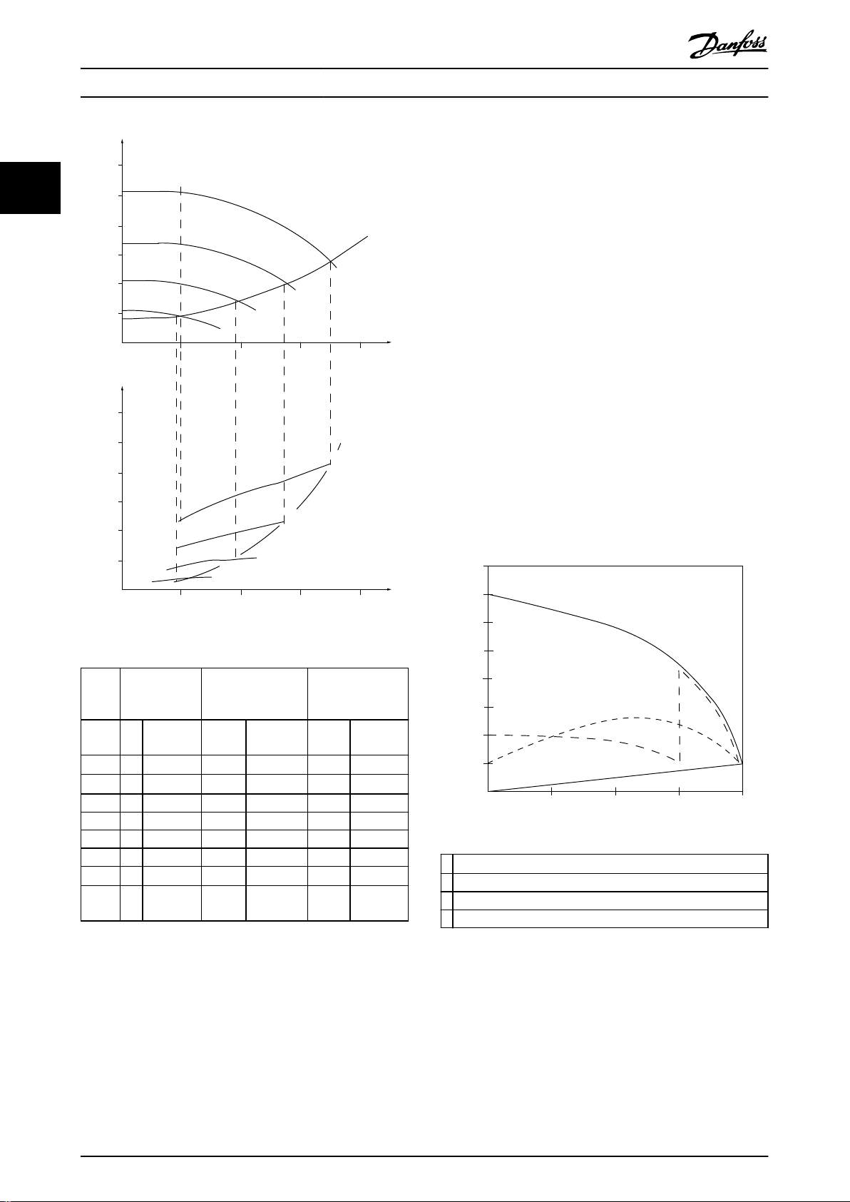
2.1.3 Example of Energy Savings
As shown in Illustration 2.2, the ow is controlled by
changing the pump speed, measured in RPM. By reducing
the speed only 20% from the rated speed, the ow is also
reduced by 20%. The ow is directly proportional to the
speed. The consumption of electricity is reduced by up to
50%.
If the system only has to supply a ow that corresponds to
100% a few days in a year, while the average is below 80%
of the rated ow for the remainder of the year, the energy
savings are even greater than 50%.
Illustration 2.2 describes the dependence of
and power consumption on pump speed in RPM for
centrifugal pumps.
ow, pressure,
2.1.4 Example with Varying Flow over 1
Year
This example is calculated based on pump characteristics
obtained from a pump datasheet, shown in Illustration 2.4.
The result obtained shows energy savings in excess of 50%
at the given ow distribution over a year,
see Illustration 2.3. The payback period depends on the
price of electricity and the price of the frequency
converter. In this example, payback is less than a year,
when compared with valves and constant speed.
2 2
t [h] Duration of ow. See also Table 2.2.
Flowrate
Illustration 2.2 Anity Laws for Centrifugal Pumps
Q
n
1
Flow:
Pressure:
Power:
1
=
Q
n
2
2
H
1
=
H
2
P
1
=
P
2
2
n
1
n
2
3
n
1
n
2
Q [m3/h]
Illustration 2.3 Flow Distribution over 1 Year (Duration versus
Flowrate)
Assuming an equal eciency in the speed range.
Q=Flow P=Power
Q1=Flow 1 P1=Power 1
Q2=Reduced ow P2=Reduced power
H=Pressure n=Speed regulation
H1=Pressure 1 n1=Speed 1
H2=Reduced pressure n2=Reduced speed
Table 2.1 Anity Laws
MG16G202 Danfoss A/S © 08/2015 All rights reserved. 15
Page 18
175HA209.11
60
50
40
30
20
10
H
s
0 100 200 300 400
(mwg)
B
C
A
750rpm
1050rpm
1350rpm
1650rpm
0
10
20
30
(kW)
40
50
60
200100 300
(
m3 /h
)
(
m3 /h
)
400
750rpm
1050rpm
1350rpm
1650rpm
P
shaft
C
1
B
1
A
1
Full load
% Full-load current
& speed
500
100
0
0 12,5 25 37,5 50Hz
200
300
400
600
700
800
4
3
2
1
175HA227.10
Product Overview
VLT® Refrigeration Drive FC 103
2.1.5 Improved Control
22
or pressure of a system.
Use a frequency converter to vary the speed of the
compressor, fan, or pump, obtaining variable control of
ow and pressure.
Furthermore, a frequency converter can quickly adapt the
speed of the compressor, fan, or pump to new ow or
pressure conditions in the system.
Obtain simple control of process (ow, level, or pressure)
utilising the built-in PI control.
2.1.6 Star/Delta Starter or Soft Starter
When large motors are started, it is necessary in many
countries to use equipment that limits the start-up current.
In more traditional systems, a star/delta starter or soft
starter is widely used. If a frequency converter is used,
such motor starters are not required.
As illustrated in Illustration 2.5, a frequency converter does
not consume more than rated current.
Use a frequency converter to improve control of the ow
Illustration 2.4 Energy Consumption at Dierent Speeds
Flow
Distribution Valve regulation Frequency
rate
% Duration Power Consump-
[m3/h]
[h] [kW] [kWh] [kW] [kWh]
350 5 438
42.5
300 15 1314 38.5 50.589 29.0 38.106
250 20 1752 35.0 61.320 18.5 32.412
200 20 1752 31.5 55.188 11.5 20.148
150 20 1752 28.0 49.056 6.5 11.388
100 20 1752
1008760 – 275.064 – 26.801
Σ
23.0
Table 2.2 Result
1) Power reading at point A1.
2) Power reading at point B1.
3) Power reading at point C1.
16 Danfoss A/S © 08/2015 All rights reserved. MG16G202
1)
2)
tion
18.615
40.296
Power Consump-
42.5
3.5
converter
control
1)
18.615
3)
tion
6.132
1
VLT® Refrigeration Drive FC 103
2 Star/delta starter
3 Soft starter
4 Start directly on mains
Illustration 2.5 Start-up Current
Page 19
Product Overview Design Guide
2.2 Description of Operation
The frequency converter supplies a regulated amount of
mains AC power to the motor to control its speed. The
frequency converter supplies variable frequency and
voltage to the motor.
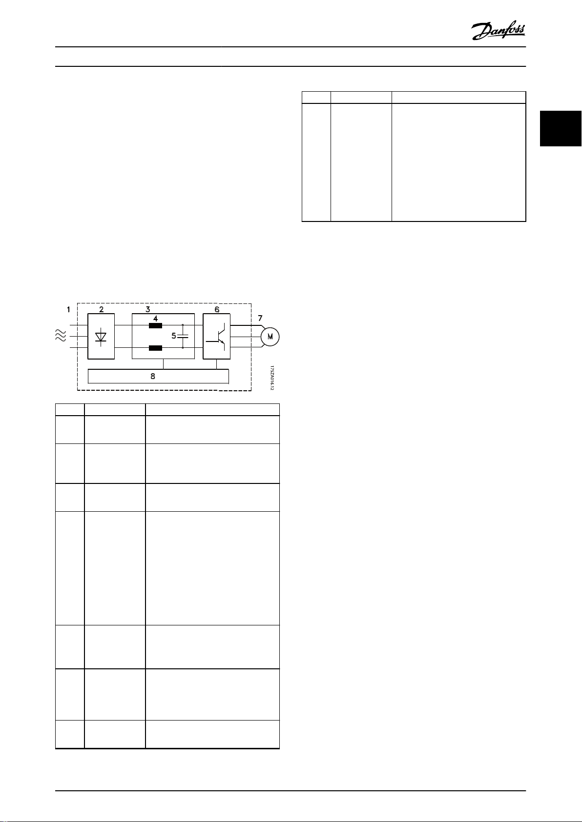
The frequency converter is divided into 4 main modules:
Rectier
•
Intermediate DC bus circuit
•
Inverter
•
Control and regulation
•
Illustration 2.6 is a block diagram of the internal
components of the frequency converter.
Area Title Functions
Input power, internal processing,
•
output, and motor current are
monitored to provide ecient
operation and control.
User interface and external
8 Control circuitry
Illustration 2.6 Frequency Converter Block Diagram
•
commands are monitored and
performed.
Status output and control can be
•
provided.
2 2
Area Title Functions
3-phase AC mains supply to the
1 Mains input
2 Rectier
3 DC bus
4 DC reactors
5 Capacitor bank
6 Inverter
7 Output to motor
•
frequency converter.
The rectier bridge converts the
•
AC input to DC current to supply
inverter power.
Intermediate DC bus circuit
•
handles the DC current.
Filter the intermediate DC circuit
•
voltage.
Prove mains transient protection.
•
Reduce RMS current.
•
Raise the power factor reected
•
back to the line.
Reduce harmonics on the AC
•
input.
Stores the DC power.
•
Provides ride-through protection
•
for short power losses.
Converts the DC into a controlled
•
PWM AC waveform for a
controlled variable output to the
motor.
Regulated 3-phase output power
•
to the motor.
MG16G202 Danfoss A/S © 08/2015 All rights reserved. 17
Page 20
Inrush
R inr
Load sharing -
Load sharing +
LC Filter (5A)
LC Filter +
(5A)
Brake
Resistor
130BA193.14
M
L2 92
L1 91
L3 93
89(+)
88(-)
R+
82
R81
U 96
V 97
W 98
P 14-50 R Filter
Product Overview
VLT® Refrigeration Drive FC 103
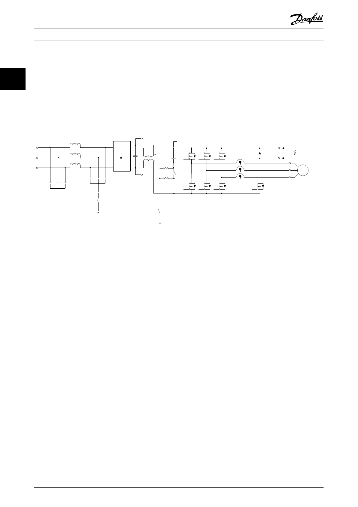
2.2.1 Control Structure Principle
speed control of 3-phased, standard asynchronous motors
and non-salient PM motors.
The frequency converter recties AC voltage from
22
•
mains into DC voltage.
The DC voltage is converted into an AC current
•
with a variable amplitude and frequency.
The frequency converter manages various motor control
principles such as U/f special motor mode and VVC+. Shortcircuit behaviour of the frequency converter depends on
the 3 current transducers in the motor phases.
The frequency converter supplies the motor with variable
voltage/current and frequency, which enables variable
Illustration 2.7 Frequency Converter Structure
2.3 Sequence of Operation
2.3.1 Rectier Section
When power is applied to the frequency converter, it
enters through the mains terminals (L1, L2, and L3).
Depending on the unit
conguration, the power moves on
to the disconnect and/or RFI lter option.
2.3.2 Intermediate Section
Following the rectier section, voltage passes to the
intermediate section. A lter circuit consisting of the DC
bus inductor and the DC bus capacitor bank smoothes the
rectied voltage.
The DC bus inductor provides series impedance to
changing current. This aids the ltering process while
reducing harmonic distortion to the input AC current
waveform normally inherent in rectier circuits.
2.3.3 Inverter Section
In the inverter section, once a run command and speed
reference are present, the IGBTs begin switching to create
the output waveform. This waveform, as generated by the
Danfoss VVC+ PWM principle at the control card, provides
optimal performance and minimal losses in the motor.
18 Danfoss A/S © 08/2015 All rights reserved. MG16G202
Page 21
130BB153.10
100%
0%
-100%
100%
P 3-13
Reference
site
Local
reference
scaled to
RPM or Hz
Auto mode
Hand mode
LCP Hand on,
o and auto
on keys
Linked to hand/auto
Local
Remote
Reference
Ramp
P 4-10
Motor speed
direction
To motor
control
Reference
handling
Remote
reference
P 4-13
Motor speed
high limit [RPM]
P 4-14
Motor speed
high limit [Hz]
P 4-11
Motor speed
low limit [RPM]
P 4-12
Motor speed
low limit [Hz]
P 3-4* Ramp 1
P 3-5* Ramp 2
P 20-81
PID Normal/Inverse
Control
PID
Ref.
Handling
Feedback
Handling
Scale to
speed
P 4-10
Motor speed
direction
To motor
control
(Illustration)
(Illustration)
130BA359.12
100%
0%
-100%
100%
*[-1]
_
+
Product Overview Design Guide
2.4 Control Structures
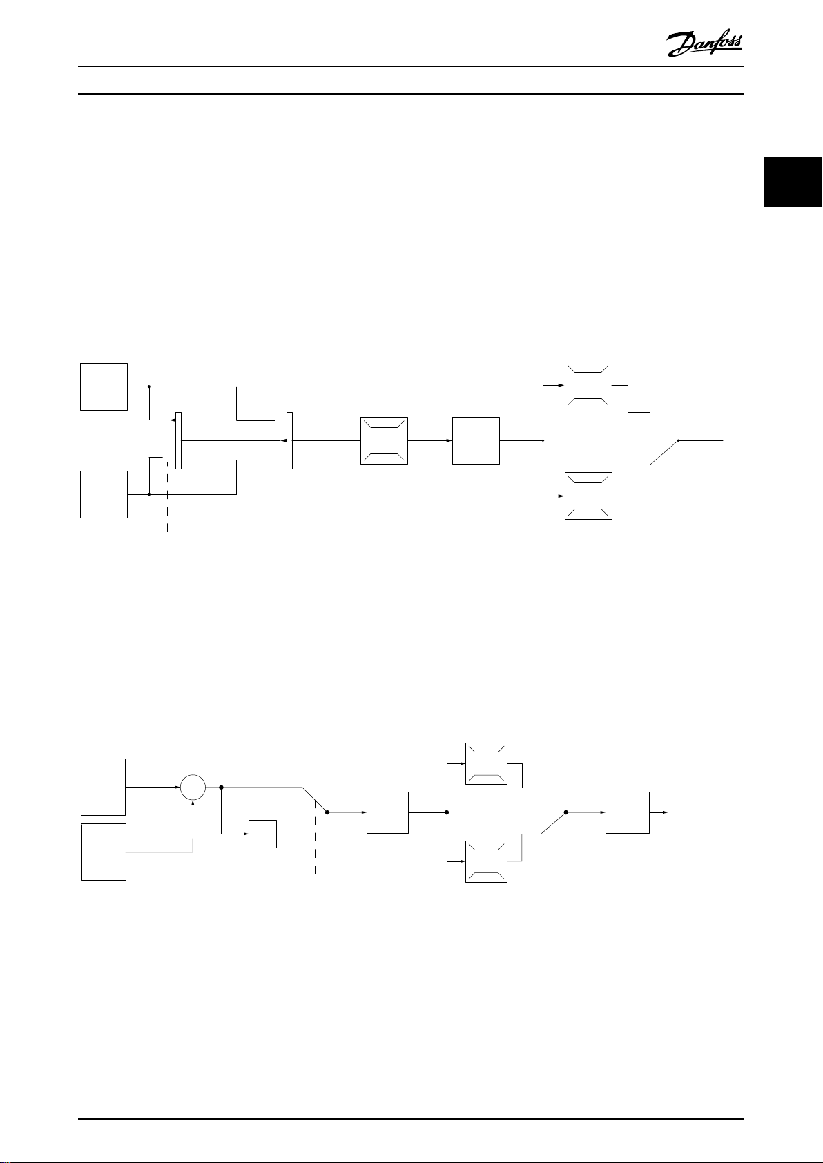
2.4.1 Control Structure Open Loop
When operating in open-loop mode, the frequency
converter responds to input commands manually via the
LCP keys or remotely via the analog/digital inputs or serial
bus.
In the conguration shown in Illustration 2.8, the frequency
converter operates in open-loop mode. It receives input
from either the LCP (Hand mode) or via a remote signal
(Auto mode). The signal (speed reference) is received and
conditioned with the following:
Programmed minimum and maximum motor
•
speed limits (in RPM and Hz).
Ramp-up and ramp-down times.
•
Motor rotation direction.
•
The reference is then passed on to control the motor.
2 2
Illustration 2.8 Block Diagram of Open-loop Mode
2.4.2 Control Structure Closed Loop
frequency converter can provide status and alarm
messages, along with many other programmable options,
In closed-loop mode, an internal PID controller allows the
frequency converter to process system reference and
for external system monitoring while operating
independently in closed loop.
feedback signals to act as an independent control unit. The
Illustration 2.9 Block Diagram of Closed-loop Controller
For example, consider a pump application in which the
speed of a pump is controlled so that the static pressure in
a pipe is constant (see Illustration 2.9). The frequency
converter receives a feedback signal from a sensor in the
system. It compares this feedback to a setpoint reference
value and determines the error, if any, between these 2
MG16G202 Danfoss A/S © 08/2015 All rights reserved. 19
signals. It then adjusts the speed of the motor to correct
this error.
The static pressure setpoint is the reference signal to the
frequency converter. A static pressure sensor measures the
actual static pressure in the pipe and provides this
Page 22
Remote
reference
Local
reference
Auto mode
Hand mode
Linked to hand/auto
Local
Remote
Reference
130BA245.11
LCP Hand on,
o and auto
on keys
P 3-13
Reference site
130BD893.10
open loop
Scale to
RPM or
Hz
Scale to
closed loop
unit
closed loop
Local
ref.
Local
reference
Conguration
mode
P 1-00
Product Overview
VLT® Refrigeration Drive FC 103
information to the frequency converter as a feedback
signal. If the feedback signal exceeds the setpoint
reference, the frequency converter ramps down to reduce
22
the pressure. Similarly, if the pipe pressure is lower than
the setpoint reference, the frequency converter ramps up
to increase the pump pressure.
While the default values for the frequency converter in
closed loop often provide satisfactory performance, system
control can often be optimised by tuning the PID
parameters. Auto tuning is provided for this optimisation.
Other programmable features include:
Inverse regulation - motor speed increases when
•
a feedback signal is high. This is useful in
compressor applications, where speed needs to
be increased if the pressure/temperarure is too
high.
Start-up frequency - lets the system quickly reach
•
an operating status before the PID controller
takes over.
Built-in lowpass lter - reduces feedback signal
•
noise.
2.4.3 Local (Hand On) and Remote (Auto
On) Control
Operate the frequency converter manually via the LCP, or
remotely via analog and digital inputs, and serial bus.
Active reference and conguration mode
The active reference is either a local reference or a remote
reference. Remote reference is the default setting.
To use the local reference, congure in Hand
•
mode. To enable Hand mode, adapt parameter
settings in parameter group 0–4* LCP Keypad. For
more information, refer to the programming
guide.
To use the remote reference, congure in Auto
•
mode, which is the default mode. In Auto mode,
it is possible to control the frequency converter
via the digital inputs and various serial interfaces
(RS485, USB, or an optional eldbus).
Illustration 2.10 shows the conguration mode
•
resulting from active reference selection, either
local or remote.
Illustration 2.11 shows manual conguration mode
•
for local reference.
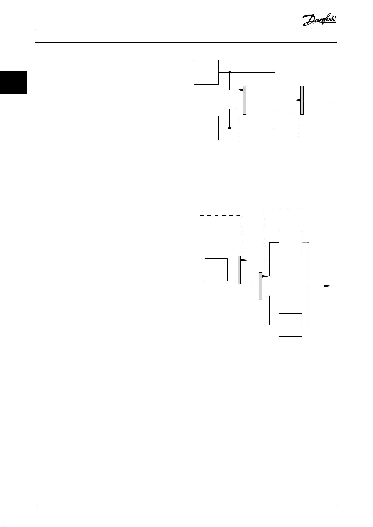
Illustration 2.10 Active Reference
Illustration 2.11 Manual Conguration Mode
Application control principle
Either the remote reference or the local reference is active
at any time. Both cannot be active simultaneously. Set the
application control principle (that is, open loop or closed
loop) in parameter 1-00 Conguration Mode, as shown in
Table 2.3.
When the local reference is active, set the application
control principle in parameter 1-05 Local Mode Congu-
ration.
Set the reference site in parameter 3-13 Reference Site, as
shown in Table 2.3.
For more information, refer to the programming guide.
20 Danfoss A/S © 08/2015 All rights reserved. MG16G202
Page 23

Product Overview Design Guide
[Hand On]
[Auto On]
LCP Keys
Hand Linked to Hand/Auto Local
Hand⇒O
Auto Linked to Hand/Auto Remote
Auto⇒O
All keys Local Local
All keys Remote Remote
Table 2.3 Local and Remote Reference Congurations
Parameter 3-13 Reference
Site
Linked to Hand/Auto Local
Linked to Hand/Auto Remote
Active Reference
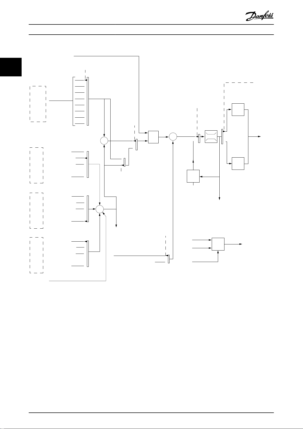
2.4.4 Reference Handling
Reference handling is applicable in both open- and closedloop operation.
Internal and external references
Up to 8 internal preset references can be programmed into
the frequency converter. The active internal preset
reference can be selected externally through digital control
inputs or the serial communications bus.
External references can also be supplied to the frequency
converter, most commonly through an analog control
input. All reference sources and the bus reference are
added to produce the total external reference. As active
reference select one of the following:
The external reference
•
The preset reference
•
The setpoint
•
The sum of all the above 3
•
The active reference can be scaled.
The scaled reference is calculated as follows:
Reference = X + X ×
Where X is the external reference, the preset reference, or
the sum of these references, and Y is parameter 3-14 Preset
Relative Reference in [%].
If Y, parameter 3-14 Preset Relative Reference, is set to 0%,
the scaling does not aect the reference.
Remote reference
A remote reference is comprised of the following (see
Illustration 2.12):
Preset references
•
External references:
•
- Analog inputs
- Pulse frequency inputs
- Digital potentiometer inputs
- Serial communication bus references
A preset relative reference
•
A feedback controlled setpoint
•
Y
100
2 2
MG16G202 Danfoss A/S © 08/2015 All rights reserved. 21
Page 24
Preset relative ref.
Preset ref.Ref. 1 source
Ext. closed loop outputs
No function
Analog inputs
Frequency inputs
No function
No function
Freeze ref.
Speed up/ speed down
ref.
Remote
Ref. in %
[1]
[2]
[3]
[4]
[5]
[6]
[7]
Open loop
Freeze ref.
&
increase/
decrease
ref.
Scale to
RPM,Hz
or %
Scale to
Closed
loop
unit
Relative
X+X*Y
/100
DigiPot
DigiPot
DigiPot
max ref.
min ref.
[0]
on
o
Conguration mode
Closed loop
Input command:
Ref. function
Ref. Preset
Input command:
Preset ref. bit0, bit1, bit2
External
reference
in %
Bus
reference
Open loop
From Feedback Handling
Setpoint
Conguration mode
Input command:
Input command:
Digipot ref.
Increase
Decrease
Clear
DigiPot
Closed loop
Ref. 2 sourceRef. 3 source
Analog inputs
Frequency inputs
Analog inputs
Frequency inputs
Ext. closed loop outputs
Ext. closed loop outputs
P 3-10P 3-15P 3-16P 3-17
Y
X
%
%
P 1-00
P 3-14
±100%
130BA357.12
P 3-04
±200%
±200%
±200%
0%
±200%
P 1-00
±200%
0/1
0/1
0/1
Product Overview
VLT® Refrigeration Drive FC 103
22
Illustration 2.12 Remote Reference Handling
22 Danfoss A/S © 08/2015 All rights reserved. MG16G202
Page 25
Setpoint 1
P 20-21
Setpoint 2
P 20-22
Setpoint 3
P 20-23
Feedback 1 Source
P 20-00
Feedback 2 Source
P 20-03
Feedback 3 Source
P 20-06
Feedback conv.
P 20-01
Feedback conv.
P 20-04
Feedback conv.
P 20-07
Feedback 1
Feedback 2
Feedback 3
Feedback
Feedback Function
P 20-20
Multi setpoint min.
Multi setpoint max.
Feedback 1 only
Feedback 2 only
Feedback 3 only
Sum (1+2+3)
Dierence (1-2)
Average (1+2+3)
Minimum (1|2|3)
Maximum (1|2|3)
Setpoint to
Reference
Handling
0%
0%
0%
0%
130BA354.12
Product Overview Design Guide
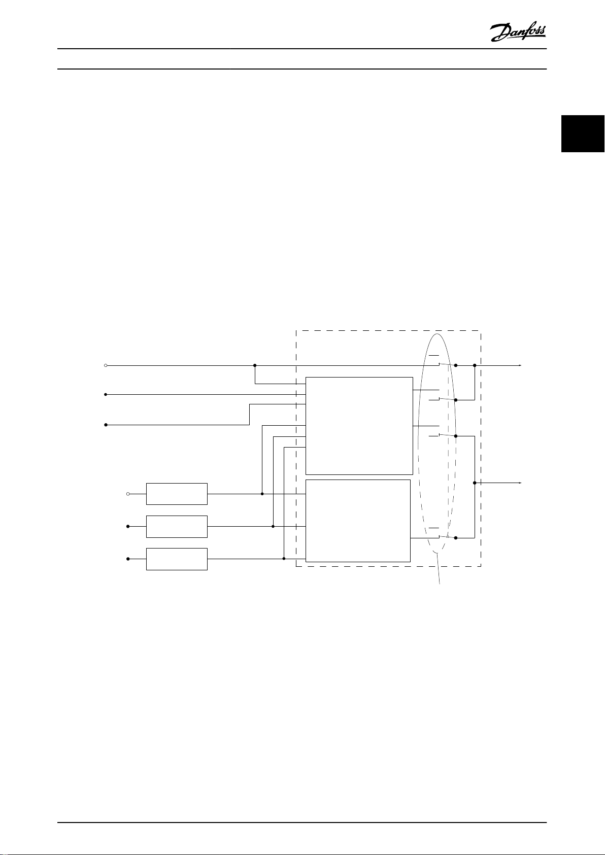
2.4.5 Feedback Handling
Feedback handling can be congured to work with
applications requiring advanced control, such as multiple
setpoints and multiple types of feedback (see
Illustration 2.13.
3 types of control are common:
Single zone, single setpoint
This control type is a basic feedback
Setpoint 1 is added to any other reference (if any) and the
feedback signal is selected.
Multi-zone, single setpoint
This control type uses 2 or 3 feedback sensors but only 1
setpoint. The feedback can be added, subtracted, or
averaged. In addition, the maximum or minimum value can
be used. Setpoint 1 is used exclusively in this congu-
ration.
conguration.
Multi-zone, setpoint/feedback
The setpoint/feedback pair with the largest dierence
controls the speed of the frequency converter. The
maximum attempts to keep all zones at or below their
respective setpoints, while minimum attempts to keep all
zones at or above their respective setpoints.
Example
A 2-zone, 2-setpoint application. Zone 1 setpoint is 15 bar,
and the feedback is 5.5 bar. Zone 2 setpoint is 4.4 bar, and
the feedback is 4.6 bar. If maximum is selected, the zone 2
setpoint and feedback are sent to the PID controller, since
it has the smaller dierence (feedback is higher than
setpoint, resulting in a negative dierence). If minimum is
selected, the zone 1 setpoint and feedback is sent to the
PID controller, since it has the larger dierence (feedback is
lower than setpoint, resulting in a positive dierence).
2 2
Illustration 2.13 Block Diagram of Feedback Signal Processing
MG16G202 Danfoss A/S © 08/2015 All rights reserved. 23
Page 26
+
-
PID
P
P
P
130BA358.11
Ref.
signal
Desired
ow
P 20-07
FB conversion
Ref.
FB
Flow
FB
signal
Flow
P 20-04
P 20-01
Product Overview
VLT® Refrigeration Drive FC 103
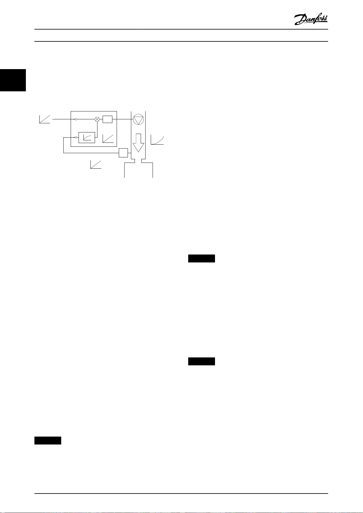
Feedback conversion
In some applications, it is useful to convert the feedback
signal. One example is using a pressure signal to provide
22
ow feedback. Since the square root of pressure is proportional to ow, the square root of the pressure signal yields
a value proportional to the ow, see Illustration 2.14.
Illustration 2.14 Feedback Conversion
2.5 Automated Operational Functions
Automated operational features are active as soon as the
frequency converter is operating. Most of them require no
programming or set-up. Understanding that these features
are present can optimise a system design and possibly
avoid introducing redundant components or functionality.
For details of any set-up required, in particular motor
parameters, refer to the programming guide.
The frequency converter has a range of built-in protection
functions to protect itself and the motor when it runs.
2.5.1 Short-circuit Protection
2.5.2 Overvoltage Protection
Motor-generated overvoltage
When the motor acts as a generator, the voltage in the DC
link increases. This behaviour occurs in the following cases:
The load drives the motor (at constant output
•
frequency from the frequency converter), for
example, the load generates energy.
During deceleration (ramp down) with high
•
inertia moment, low friction, and a too short
ramp-down time for the energy to be dissipated
as a loss in the frequency converter, the motor,
and the installation.
Incorrect slip compensation setting may cause
•
higher DC-link voltage.
Back EMF from PM motor operation. If coasted at
•
high RPM, the PM motor back EMF may
potentially exceed the maximum voltage
tolerance of the frequency converter and cause
damage. To prevent this situation, the value of
parameter 4-19 Max Output Frequency is automatically limited via an internal calculation based on
the value of parameter 1-40 Back EMF at 1000
RPM, parameter 1-25 Motor Nominal Speed, and
parameter 1-39 Motor Poles.
NOTICE
To avoid motor overspeeding (for example due to
excessive windmilling eects or uncontrolled water ow),
equip the frequency converter with a brake resistor.
Handle the overvoltage by either using a brake function
(parameter 2-10 Brake Function) or using overvoltage
control (parameter 2-17 Over-voltage Control).
Motor (phase-phase)
The frequency converter is protected against short circuits
on the motor side by current measurement in each of the
motor phases or in the DC link. A short circuit between 2
output phases causes an overcurrent in the inverter. The
inverter is turned o when the short-circuit current
exceeds the permitted value (Alarm 16, Trip Lock).
Mains side
A frequency converter that works correctly limits the
current it can draw from the supply. Use fuses and/or
circuit breakers on the supply side as protection in case of
component break-down inside the frequency converter
(rst fault). See chapter 7.8 Fuses and Circuit Breakers for
more information.
NOTICE
To ensure compliance with IEC 60364 for CE or NEC 2009
for UL, it is mandatory to use fuses and/or circuit
breakers.
24 Danfoss A/S © 08/2015 All rights reserved. MG16G202
Overvoltage control (OVC)
OVC reduces the risk of the frequency converter tripping
due to an overvoltage on the DC-link. This is managed by
automatically extending the ramp-down time.
NOTICE
OVC can be activated for PM motors (PM VVC+).
2.5.3 Missing Motor Phase Detection
The missing motor phase function (parameter 4-58 Missing
Motor Phase Function) is enabled by default to avoid motor
damage in the case that a motor phase is missing. The
default setting is 1000 ms, but it can be adjusted for a
faster detection.
Page 27

Product Overview Design Guide
2.5.4 Mains Phase Imbalance Detection
Operation under severe mains imbalance conditions
reduces the lifetime of the motor. If the motor is operated
continuously near nominal load, conditions are considered
severe. The default setting trips the frequency converter in
case of mains imbalance (parameter 14-12 Function at
Mains Imbalance).
2.5.5 Switching on the Output
Adding a switch to the output between the motor and the
frequency converter is permitted. Fault messages may
appear. To catch a spinning motor, enable ying start.
2.5.6 Overload Protection
Torque limit
The torque limit feature protects the motor against
overload, independent of the speed. Torque limit is
controlled in parameter 4-16 Torque Limit Motor Mode or
parameter 4-17 Torque Limit Generator Mode, and the time
before the torque limit warning trips is controlled in
parameter 14-25 Trip Delay at Torque Limit.
Current limit
The current limit is controlled in parameter 4-18 Current
Limit.
Speed limit
Dene lower and upper limits for the operating speed
range using 1 or more of the following parameters:
Parameter 4-11 Motor Speed Low Limit [RPM].
•
Parameter 4-12 Motor Speed Low Limit [Hz] and
•
parameter 4-13 Motor Speed High Limit [RPM].
Parameter 4-14 Motor Speed High Limit [Hz].
•
For example, the operating speed range can be dened as
between 30 and 50/60 Hz.
Parameter 4-19 Max Output Frequency limits the maximum
output speed the frequency converter can provide.
ETR
ETR is an electronic feature that simulates a bimetal relay
based on internal measurements. The characteristic is
shown in Illustration 2.15.
Voltage limit
When a certain hard-coded voltage level is reached, the
frequency converter turns o to protect the transistors and
the DC link capacitors.
Overtemperature
The frequency converter has built-in temperature sensors
and reacts immediately to critical values via hard-coded
limits.
2.5.7 Automatic Derating
The frequency converter constantly checks for critical
levels:
High temperature on the control card or heat sink
•
High motor load
•
High DC-link voltage
•
Low motor speed
•
As a response to a critical level, the frequency converter
adjusts the switching frequency. For high internal temperatures and low motor speed, the frequency converters can
also force the PWM pattern to SFAVM.
NOTICE
The automatic derating is dierent when
parameter 14-55 Output Filter is set to [2] Sine-Wave Filter
Fixed.
2.5.8 Automatic Energy Optimisation
Automatic energy optimisation (AEO) directs the frequency
converter to monitor the load on the motor continuously
and adjust the output voltage to maximise eciency.
Under light load, the voltage is reduced and the motor
current is minimised. The motor benets from:
Increased eciency.
•
Reduced heating.
•
Quieter operation.
•
There is no need to select a V/Hz curve because the
frequency converter automatically adjusts motor voltage.
2.5.9 Automatic Switching Frequency
Modulation
The frequency converter generates short electrical pulses
to form an AC wave pattern. The switching frequency is
the rate of these pulses. A low switching frequency (slow
pulsing rate) causes audible noise in the motor, making a
higher switching frequency preferable. A high switching
frequency, however, generates heat in the frequency
converter which can limit the amount of current available
to the motor.
Automatic switching frequency modulation regulates these
conditions automatically to provide the highest switching
frequency without overheating the frequency converter. By
providing a regulated high switching frequency, it quiets
motor operating noise at slow speeds, when audible noise
control is critical, and produces full output power to the
motor when required.
2 2
MG16G202 Danfoss A/S © 08/2015 All rights reserved. 25
Page 28

Product Overview
VLT® Refrigeration Drive FC 103
2.5.10 Automatic Derating for High
2.5.14 Power Fluctuation Performance
Switching Frequency
22
The frequency converter is designed for continuous, fullload operation at switching frequencies between 3.0 and
4.5 kHz (this frequency range depends on power size). A
switching frequency exceeding the maximum permissible
range generates increased heat in the frequency converter
and requires the output current to be derated.
An automatic feature of the frequency converter is loaddependent switching frequency control. This feature allows
the motor to
the load allow.
benet from as high a switching frequency as
2.5.11 Automatic Derating for
The frequency converter withstands mains uctuations
such as:
Transients.
•
Momentary drop-outs.
•
Short voltage drops.
•
Surges.
•
The frequency converter automatically compensates for
input voltages ±10% from the nominal to provide full rated
motor voltage and torque. With auto restart selected, the
frequency converter automatically powers up after a
voltage trip. With
synchronises to motor rotation before start.
ying start, the frequency converter
Overtemperature
Automatic overtemperature derating works to prevent
tripping the frequency converter at high temperature.
Internal temperature sensors measure conditions to protect
the power components from overheating. The frequency
converter can automatically reduce the switching
frequency to maintain the operating temperature within
safe limits. After reducing the switching frequency, the
frequency converter can also reduce the output frequency
and current by as much as 30% to avoid an overtemperature trip.
2.5.15 Motor Soft Start
The frequency converter supplies the right amount of
current to the motor to overcome load inertia and bring
the motor up to speed. This avoids full mains voltage
being applied to a stationary or slow-turning motor, which
generates high current and heat. This inherent soft start
feature reduces thermal load and mechanical stress,
extends motor life, and provides quieter system operation.
2.5.16 Resonance Damping
2.5.12 Auto Ramping
A motor trying to accelerate a load too quickly for the
current available can cause the frequency converter to trip.
The same is true for too quick a deceleration. Auto
ramping protects against these situations by extending the
motor ramping rate (acceleration or deceleration) to match
the available current.
2.5.13 Current Limit Circuit
When a load exceeds the current capability of the
frequency converter normal operation (from an undersized
frequency converter or motor), current limit reduces the
output frequency to ramp down the motor and reduce the
load. An adjustable timer is available to limit operation in
this condition for 60 s or less. The factory default limit is
110% of the rated motor current to minimise overcurrent
stress.
Eliminate high frequency motor resonance noise through
resonance damping. Automatic or manually selected
frequency damping is available.
2.5.17 Temperature-controlled Fans
Sensors in the frequency converter control the temperature
of the internal cooling fans. Often, the cooling fans do not
run during low load operation, or when in sleep mode or
standby. This reduces noise, increases eciency, and
extends the operating life of the fan.
2.5.18 EMC Compliance
Electromagnetic interference (EMI) or radio frequency
interference (RFI, in case of radio frequency) is disturbance
that can aect an electrical circuit due to electromagnetic
induction or radiation from an external source. The
frequency converter is designed to comply with the EMC
product standard for frequency converters IEC 61800-3 as
well as the European standard EN 55011. To comply with
the emission levels in EN 55011, screen and terminate the
motor cable properly terminated. For more information
regarding EMC performance, see chapter 3.2.2 EMC Test
Results (Emission).
26 Danfoss A/S © 08/2015 All rights reserved. MG16G202
Page 29
1.21.0 1.4
30
10
20
100
60
40
50
1.81.6 2.0
2000
500
200
400
300
1000
600
t [s]
175ZA052.12
f
OUT
= 2 x f
M,N
f
OUT
= 0.2 x f
M,N
f
OUT
= 1 x f
M,N
(par. 1-23)
IMN(par. 1-24)
I
M
Product Overview Design Guide
2.5.19 Current Measurement on All Three
Motor Phases
Output current to the motor is continuously measured on
all 3 phases to protect the frequency converter and motor
against short circuits, ground faults, and phase loss. Output
ground faults are instantly detected. If a motor phase is
lost, the frequency converter stops immediately and
reports which phase is missing.
2.5.20 Galvanic Isolation of Control
Terminals
All control terminals and output relay terminals are galvanically isolated from mains power. This means the controller
circuitry is completely protected from the input current.
The output relay terminals require their own grounding.
This isolation meets the stringent protective extra-low
voltage (PELV) requirements for isolation.
The components that make up the galvanic isolation are:
Power supply, including signal isolation.
•
Gate drive for the IGBTs, trigger transformers, and
•
optocouplers.
The output current Hall eect transducers.
•
2.6.2 Motor Thermal Protection
Motor thermal protection can be provided in 3 ways:
Via direct temperature sensing via the PTC sensor
•
in the motor windings and connected on a
standard AI or DI.
Mechanical thermal switch (Klixon type) on a DI.
•
Via the built-in electronic thermal relay (ETR) for
•
asynchronous motors.
ETR calculates motor temperature by measuring current,
frequency, and operating time. The frequency converter
shows the thermal load on the motor in percentage and
can issue a warning at a programmable overload setpoint.
Programmable options at the overload allow the frequency
converter to stop the motor, reduce output, or ignore the
condition. Even at low speeds, the frequency converter
meets I2t Class 20 electronic motor overload standards.
2 2
Custom Application Functions
2.6
Custom application functions are the most common
features programmed in the frequency converter for
enhanced system performance. They require minimum
programming or set-up. Understanding that these
functions are available can optimise the system design and
possibly avoid introducing redundant components or
functionality. See the programming guide for instructions
on activating these functions.
2.6.1 Automatic Motor Adaptation
Automatic motor adaptation (AMA) is an automated test
procedure used to measure the electrical characteristics of
the motor. AMA provides an accurate electronic model of
the motor. It allows the frequency converter to calculate
optimal performance and eciency with the motor.
Running the AMA procedure also maximises the automatic
energy optimisation feature of the frequency converter.
AMA is performed without the motor rotating and without
uncoupling the load from the motor.
MG16G202 Danfoss A/S © 08/2015 All rights reserved. 27
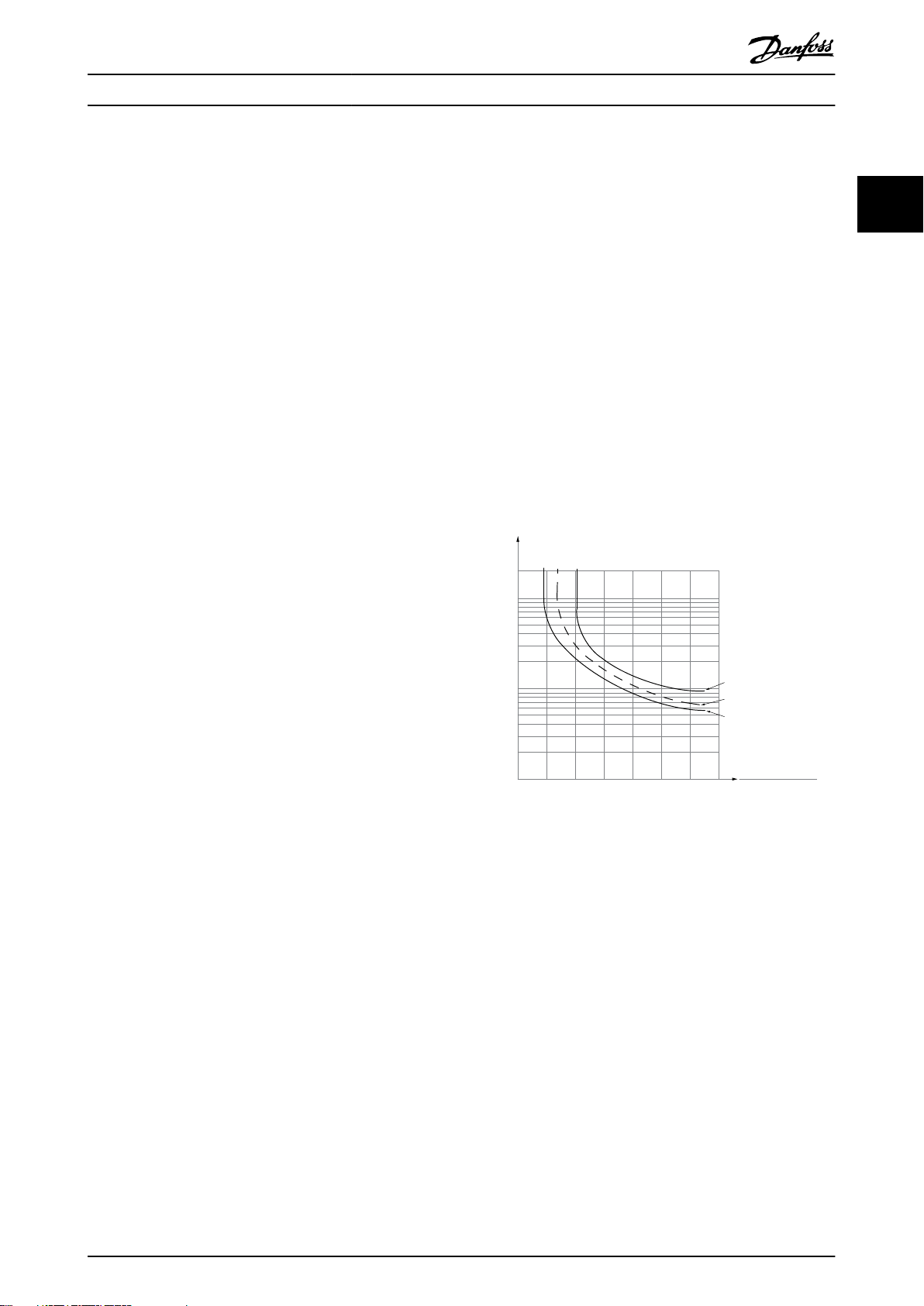
Illustration 2.15 ETR Characteristics
The X-axis in Illustration 2.15 shows the ratio between I
and I
before the ETR cuts o and trips the frequency converter.
The curves show the characteristic nominal speed, at twice
the nominal speed and at 0.2 x the nominal speed.
At lower speed, the ETR cuts o at lower heat due to less
cooling of the motor. In that way, the motor is protected
from being overheated even at low speed. The ETR feature
calculates the motor temperature based on actual current
and speed. The calculated temperature is visible as a
readout parameter in parameter 16-18 Motor Thermal.
nominal. The Y-axis shows the time in seconds
motor
2.6.3 Mains Drop-out
During a mains drop-out, the frequency converter keeps
running until the DC-link voltage drops below the
minimum stop level. The minimum stop level is typically
15% below the lowest rated supply voltage. The mains
motor
Page 30

Product Overview
VLT® Refrigeration Drive FC 103
voltage before the drop-out and the motor load
determines how long it takes for the frequency converter
to coast.
22
Congure the frequency converter(parameter 14-10 Mains
Failure) to dierent types of behaviour during mains drop-
out,
Trip lock once the DC link is exhausted.
•
Coast with ying start whenever mains return
•
(parameter 1-73 Flying Start).
Kinetic back-up.
•
Controlled ramp down.
•
Flying start
This selection makes it possible to catch a motor that spins
freely due to a mains drop-out. This option is relevant for
centrifuges and fans.
Kinetic back-up
This selection ensures that the frequency converter runs as
long as there is energy in the system. For short mains
drop-out, the operation is restored after mains return,
without bringing the application to a stop or losing control
at any time. Several variants of kinetic back-up can be
selected.
Congure the behaviour of the frequency converter at
mains drop-out, in parameter 14-10 Mains Failure and
parameter 1-73 Flying Start.
NOTICE
Coast is recommended for compressors as the inertia is
too small for ying start in most situations.
2.6.5 Automatic Restart
The frequency converter can be programmed to restart the
motor automatically after a minor trip, such as momentary
power loss or uctuation. This feature eliminates the need
for manual resetting and enhances automated operation
for remotely controlled systems. The number of restart
attempts as well as the duration between attempts can be
limited.
2.6.6 Flying Start
Flying start allows the frequency converter to synchronise
with an operating motor rotating at up to full speed, in
either direction. This prevents trips due to overcurrent
draw. It minimises mechanical stress to the system since
the motor receives no abrupt change in speed when the
frequency converter starts.
2.6.7 Full Torque at Reduced Speed
The frequency converter follows a variable V/Hz curve to
provide full motor torque even at reduced speeds. Full
output torque can coincide with the maximum designed
operating speed of the motor. This diers from variable
torque frequency converters and constant torque
frequency converters. Variable torque frequency converters
provide reduced motor torque at low speed. Constant
torque frequency converters provide excess voltage, heat,
and motor noise at less than full speed.
2.6.8 Frequency Bypass
2.6.4 Built-in PID Controllers
The 4 built-in proportional, integral, derivative (PID)
controllers eliminate the need for auxiliary control devices.
One of the PID controllers maintains constant control of
closed-loop systems where regulated pressure, ow,
temperature, or other system requirements are maintained.
The frequency converter can provide self-reliant control of
the motor speed in response to feedback signals from
remote sensors. The frequency converter accommodates 2
feedback signals from 2 dierent devices. This feature
allows regulating a system with dierent feedback
requirements. The frequency converter makes control
decisions by comparing the 2 signals to optimise system
performance.
Use the 3 additional and independent controllers for
controlling other process equipment, such as chemical feed
pumps, valve control, or for aeration with
dierent levels.
In some applications, the system may have operational
speeds that create a mechanical resonance. This can
generate excessive noise and possibly damage mechanical
components in the system. The frequency converter has 4
programmable bypass-frequency bandwidths. These allow
the motor to step over speeds that induce system
resonance.
2.6.9 Motor Preheat
To preheat a motor in a cold or damp environment, a small
amount of DC current can be trickled continuously into the
motor to protect it from condensation and cold starts. This
can eliminate the need for a space heater.
28 Danfoss A/S © 08/2015 All rights reserved. MG16G202
Page 31

. . .
. . .
Par. 13-11
Comparator Operator
Par. 13-43
Logic Rule Operator 2
Par. 13-51
SL Controller Event
Par. 13-52
SL Controller Action
130BB671.13
Coast
Start timer
Set Do X low
Select set-up 2
. . .
Running
Warning
Torque limit
Digital input X 30/2
. . .
=
TRUE longer than..
. . .
. . .
130BA062.14
State 1
13-51.0
13-52.0
State 2
13-51.1
13-52.1
Start
event P13-01
State 3
13-51.2
13-52.2
State 4
13-51.3
13-52.3
Stop
event P13-02
Stop
event P13-02
Stop
event P13-02
Product Overview Design Guide
2.6.10 Four Programmable Set-ups
The frequency converter has 4 set-ups that can be
independently programmed. Using multi-setup, it is
possible to switch between independently programmed
functions activated by digital inputs or a serial command.
Independent set-ups are used, for example, to change
references, or for day/night or summer/winter operation, or
to control multiple motors. The LCP shows the active setup.
Set-up data can be copied from frequency converter to
frequency converter by downloading the information from
the removable LCP.
2.6.11 DC Braking
Some applications may require braking a motor to slow or
stopping it. Applying DC current to the motor brakes the
motor and eliminates the need for a separate motor brake.
DC brake can be set to activate at a predetermined
frequency or after receiving a signal. The rate of braking
can also be programmed.
2.6.12 Sleep Mode
Sleep mode automatically stops the motor when demand
is low for a specied time. When the system demand
increases, the frequency converter restarts the motor. Sleep
mode provides energy savings and reduces motor wear.
Unlike a setback clock, the frequency converter is always
available to run when the preset wake-up demand is
reached.
2.6.13 Run Permissive
The frequency converter can wait for a remote system
ready signal before starting. When this feature is active, the
frequency converter remains stopped until receiving
permission to start. Run permissive ensures that the system
or auxiliary equipment is in the proper state before the
frequency converter is allowed to start the motor.
2.6.14 Smart Logic Control (SLC)
Smart logic control (SLC) is a sequence of user-dened
actions (see parameter 13-52 SL Controller Action [x])
executed by the SLC when the associated user-dened
event (see parameter 13-51 SL Controller Event [x]) is
evaluated as TRUE by the SLC.
The condition for an event can be a particular status or
that the output from a logic rule or a comparator operand
becomes TRUE. That leads to an associated action as
shown in Illustration 2.16.
MG16G202 Danfoss A/S © 08/2015 All rights reserved. 29
Illustration 2.16 SLC Event and Action
Events and actions are each numbered and linked in pairs
(states). This means that when event [0] is fullled (attains
the value TRUE), action [0] is executed. After this, the
conditions of event [1] is evaluated and if evaluated TRUE,
action [1] is executed and so on. Only one event is
evaluated at any time. If an event is evaluated as FALSE,
nothing happens (in the SLC) during the current scan
interval and no other events are evaluated. This means
that when the SLC starts, it evaluates event [0] (and only
event [0]) each scan interval. Only when event [0] is
evaluated TRUE, the SLC executes action [0] and starts
evaluating event [1]. It is possible to programme from 1 to
20 events and actions.
When the last event/action has been executed, the
sequence starts over again from event [0]/action [0].
Illustration 2.17 shows an example with 4 event/actions:
Illustration 2.17 Order of Execution when 4 Events/Actions are
Programmed
2 2
Page 32

Par. 13-11
Comparator Operator
=
TRUE longer than.
. . .
. . .
Par. 13-10
Comparator Operand
Par. 13-12
Comparator Value
130BB672.10
. . .
. . .
. . .
. . .
Par. 13-43
Logic Rule Operator 2
Par. 13-41
Logic Rule Operator 1
Par. 13-40
Logic Rule Boolean 1
Par. 13-42
Logic Rule Boolean 2
Par. 13-44
Logic Rule Boolean 3
130BB673.10
Product Overview
VLT® Refrigeration Drive FC 103
Comparators
Comparators are used for comparing continuous variables
(output frequency, output current, analog input, and so on)
22
to xed preset values.
Illustration 2.18 Comparators
Logic rules
Combine up to 3 boolean inputs (TRUE/FALSE inputs) from
timers, comparators, digital inputs, status bits, and events
using the logical operators AND, OR, and NOT.
Illustration 2.19 Logic Rules
The logic rules, timers, and comparators are also available
for use outside of the SLC sequence.
For an example of SLC, refer to chapter 4.3 Application Set-
up Examples.
2.6.15 Safe Torque O Function
The frequency converter is available with Safe Torque O
(STO) functionality via control terminal 37. STO disables the
control voltage of the power semiconductors of the
frequency converter output stage. This in turn prevents
generating the voltage required to rotate the motor. When
the STO (terminal 37) is activated, the frequency converter
issues an alarm, trips the unit, and coasts the motor to a
stop. Manual restart is required. The STO function can be
used as an emergency stop for the frequency converter. In
the normal operating mode when STO is not required, use
the regular stop function. When using automatic restart,
ensure the requirements of ISO 12100-2 paragraph 5.3.2.5
are fullled.
Liability conditions
It is the responsibility of the user to ensure personnel
installing and operating the STO function:
Read and understand the safety regulations
•
concerning health, safety, and accident
prevention.
Have a good knowledge of the generic and safety
•
standards applicable to the specic application.
A user is dened as:
Integrator.
•
Operator.
•
Service technician.
•
Maintenance technician.
•
Standards
Use of STO on terminal 37 requires that the user fullls all
provisions for safety including relevant laws, regulations,
and guidelines. The optional STO function complies with
the following standards:
EN 954-1: 1996 Category 3
•
IEC 60204-1: 2005 category 0 – uncontrolled stop
•
IEC 61508: 1998 SIL2
•
IEC 61800-5-2: 2007 – STO function
•
IEC 62061: 2005 SIL CL2
•
ISO 13849-1: 2006 Category 3 PL d
•
ISO 14118: 2000 (EN 1037) – prevention of
•
unexpected start-up
The listed information and instructions are not sucient
for a proper and safe use of the STO functionality. For full
information about STO, refer to the VLT® Safe Torque O
Operating Instructions.
Protective measures
Qualied and skilled personnel are required for
•
installation and commissioning of safety
engineering systems.
Install the unit in an IP54 enclosure or in an
•
equivalent environment. In special applications, a
higher IP degree is required.
The cable between terminal 37 and the external
•
safety device must be short circuit protected
according to ISO 13849-2 table D.4.
When external forces inuence the motor axis (for
•
example, suspended loads), to eliminate potential
hazards, additional measures are required (for
example, a safety holding brake).
30 Danfoss A/S © 08/2015 All rights reserved. MG16G202
Page 33

Product Overview Design Guide
2.7 Fault, Warning and Alarm Functions
The frequency converter monitors many aspects of system
operation including mains conditions, motor load, and
performance, as well as frequency converter status. An
alarm or warning does not necessarily indicate a problem
with the frequency converter itself. It may be a condition
outside of the frequency converter that is being monitored
for performance limits. The frequency converter has various
pre-programmed fault, warning, and alarm responses.
Select additional alarm and warning features to enhance or
modify system performance.
This section describes common alarm and warning
features. Understanding that these features are available
can optimise a system design and possibly avoid
introducing redundant components or functionality.
2.7.1 Operation at Overtemperature
By default, the frequency converter issues an alarm and
trip at overtemperature. If Autoderate and Warning is
selected, the frequency converter warns of the condition
but continues to run and attempt to cool itself by rst
reducing its switching frequency. Then, if necessary, it
reduces the output frequency.
capacitors. Other options are to issue a warning and
reduce output current to 30% of full current or to issue a
warning and continue normal operation. Operating a unit
connected to an imbalanced line may be desirable until
the imbalance is corrected.
2.7.5 High Frequency Warning
When staging on additional equipment such as
compressors or cooling fans, the frequency converter can
warn when the motor speed is high. A specic high
frequency setting can be entered into the frequency
converter. If the output exceeds the set warning frequency,
the unit shows a high frequency warning. A digital output
from the frequency converter can signal external devices
to stage on.
2.7.6 Low Frequency Warning
When staging o equipment, the frequency converter can
warn when the motor speed is low. A specic low
frequency setting can be selected for warning and to stage
o external devices. The unit does not issue a low
frequency warning when it stops nor after start-up until
after the operating frequency has been reached.
2 2
Autoderating does not replace the user settings for
derating for ambient temperature (see chapter 5.4 Derating
for Ambient Temperature).
2.7.2 High and Low Reference Warning
In open-loop operation, the reference signal directly
determines the speed of the frequency converter. The
display shows a ashing reference high or low warning
when the programmed maximum or minimum is reached.
2.7.3 High and Low Feedback Warning
In closed-loop operation, the frequency converter monitors
the selected high and low feedback values. The display
shows a ashing high or ashing low warning when
appropriate. The frequency converter can also monitor
feedback signals in open-loop operation. While the signals
do not aect the operation of the frequency converter in
open loop, they can be useful for system status indication
locally or via serial communication. The frequency
converter handles 39 dierent units of measure.
2.7.4 Phase Imbalance or Phase Loss
2.7.7 High Current Warning
This function is similar to high frequency warning, except a
high current setting is used to issue a warning and stage
on additional equipment. The function is not active when
stopped or at start-up until the set operating current has
been reached.
2.7.8 Low Current Warning
This function is similar to low frequency warning (see
chapter 2.7.6 Low Frequency Warning), except a low current
setting is used to issue a warning and stage o equipment.
The function is not active when stopped or at start-up
until the set operating current has been reached.
2.7.9 No Load/Broken Belt Warning
This feature can be used for monitoring a no-load
condition, for example a V-belt. After a low current limit
has been stored in the frequency converter, if loss of the
load is detected, the frequency converter can be
programmed to issue an alarm and trip or to continue
operation and issue a warning.
Excessive ripple current in the DC bus indicates either a
mains phase imbalance or a phase loss. When a power
phase to the frequency converter is lost, the default action
is to issue an alarm and trip the unit to protect the DC bus
MG16G202 Danfoss A/S © 08/2015 All rights reserved. 31
Page 34

130BP066.10
1107 RPM
0 -
**
Operation/Display
1 -
**
Load/Motor
2 -
**
Brakes
3 -
**
Reference / Ramps
3.84 A 1 (1)
Main Menu
Auto
on
Reset
Hand
on
Off
Status
Quick
Menu
Main
Menu
Alarm
Log
Back
Cancel
Info
OK
Status
1(1)
1234rpm 10,4A 43,5Hz
Run OK
43,5Hz
On
Alarm
Warn.
130BB465.10
a
b
c
d
Product Overview
VLT® Refrigeration Drive FC 103
2.7.10 Lost Serial Interface
22
The frequency converter can detect loss of serial communication. A time delay of up to 99 s is selectable to avoid a
response due to interruptions on the serial communications bus. When the delay is exceeded, options available
include for the unit to:
Maintain its last speed.
•
Go to maximum speed.
•
Go to a preset speed.
•
Stop and issue a warning.
•
2.8 User Interfaces and Programming
The frequency converter uses parameters for programming
its application functions. Parameters provide a description
of a function and a menu of options to either select from
or for entering numeric values. A sample programming
menu is shown in Illustration 2.20.
part number 130B1000. A user’s manual provides detailed
operation instructions. See also chapter 2.8.2 PC Software.
Programming control terminals
Each control terminal has specied functions it is
•
capable of performing.
Parameters associated with the terminal enable
•
the function selections.
For proper frequency converter functioning using
•
control terminals, the terminals must be:
- Wired properly.
- Programmed for the intended function.
2.8.1 Local Control Panel
The local control panel (LCP) is a graphic display on the
front of the unit, which provides the user interface through
push-button controls and shows status messages, warnings
and alarms, programming parameters, and more. A
numeric display is also available with limited display
options. Illustration 2.21 shows the LCP.
Illustration 2.20 Sample Programming Menu
Local user interface
For local programming, parameters are accessible by
pressing either [Quick Menu] or [Main Menu] on the LCP.
The Quick Menu is intended for initial start-up and motor
characteristics. The Main Menu accesses all parameters and
allows for advanced applications programming.
Remote user interface
For remote programming, Danfoss oers a software
program for developing, storing, and transferring
programming information. MCT 10 Set-up Software allows
the user to connect a PC to the frequency converter and
perform live programming rather than using the LCP
keypad. Or programming can be done o-line and
downloaded to the unit. The entire frequency converter
prole can be loaded onto the PC for back-up storage or
analysis. A USB connector and RS485 terminal are available
for connecting to the frequency converter.
MCT 10 Set-up Software is available for free download at
www.VLT-software.com. A CD is also available by requesting
Illustration 2.21 Local Control Panel
32 Danfoss A/S © 08/2015 All rights reserved. MG16G202
Page 35

130BT308.10
Product Overview Design Guide
2.8.2 PC Software
The PC is connected via a standard (host/device) USB
cable, or via the RS485 interface.
USB is a serial bus utilising 4 screened wires with ground
pin 4 connected to the screen in the PC USB port. By
connecting the PC to a frequency converter through the
USB cable, there is a potential risk of damaging the PC USB
host controller. All standard PCs are manufactured without
galvanic isolation in the USB port.
Any ground potential dierence caused by not following
the recommendations described in the operating
instructions, can damage the USB host controller through
the screen of the USB cable.
When connecting the PC to a frequency converter through
a USB cable, use a USB isolator with galvanic isolation to
protect the PC USB host controller from ground potential
dierences.
Do not use a PC power cable with a ground plug when
the PC is connected to the frequency converter through a
USB cable. It reduces the ground potential dierence, but
does not eliminate all potential dierences due to the
ground and screen connected in the PC USB port.
Example 1: Data storage in PC via MCT 10 Set-up
Software
1. Connect a PC to the unit via USB or via the RS485
interface.
2. Open MCT 10 Set-up Software.
3. Select the USB port or the RS485 interface.
4. Select copy.
5. Select the project section.
6. Select paste.
7. Select save as.
All parameters are now stored.
Example 2: Data transfer from PC to frequency converter
via MCT 10 Set-up Software
1. Connect a PC to the unit via USB port or via the
RS485 interface.
2. Open MCT 10 Set-up Software.
3. Select Open – stored les are shown.
4. Open the appropriate le.
5. Select Write to drive.
All parameters are now transferred to the frequency
converter.
A separate manual for MCT 10 Set-up Software is available.
Download the software and the manual from
www.danfoss.com/BusinessAreas/DrivesSolutions/Softwaredownload/.
2 2
Illustration 2.22 USB Connection
2.8.2.1 MCT 10 Set-up Software
The MCT 10 Set-up Software is designed for commissioning and servicing the frequency converter including
guided programming of pack controller, real time clock,
smart logic controller, and preventive maintenance.
This software provides easy control of details as well as a
general overview of systems, large, or small. The tool
handles all frequency converter series, VLT® Advanced
Active Filters AAF 006 and VLT® Soft Starter-related data.
2.8.2.2
VLT® Harmonics Calculation
Software MCT 31
The MCT 31 Harmonic Calculation PC tool enables easy
estimation of the harmonic distortion in a given
application. Both the harmonic distortion of Danfoss
frequency converters as well as non-Danfoss frequency
converters with additional harmonic reduction devices,
such as Danfoss VLT® Advanced Harmonic Filters AHF
005/AHF 010 lters and 12–18 pulse rectiers, can be
calculated.
MCT 31 can also be downloaded from www.danfoss.com/
BusinessAreas/DrivesSolutions/Softwaredownload/.
2.8.2.3 Harmonic Calculation Software
(HCS)
HCS is an advanced version of the harmonic calculation
tool. The calculated results are compared to relevant norms
and can be printed afterwards.
For more information, see www.danfoss-hcs.com/
Default.asp?LEVEL=START
MG16G202 Danfoss A/S © 08/2015 All rights reserved. 33
Page 36

Product Overview
VLT® Refrigeration Drive FC 103
2.9 Maintenance
Danfoss frequency converter models up to 90 kW are
22
maintenance-free. High-power frequency converters (rated
at 110 kW or higher) have built-in lter mats, which require
periodic cleaning by the operator, depending on the
exposure to dust and contaminants. Maintenance intervals
for the cooling fans (approximately 3 years) and capacitors
(approximately 5 years) are recommended in most
environments.
2.9.1 Storage
Like all electronic equipment, frequency converters must
be stored in a dry location. Periodic forming (capacitor
charging) is not necessary during storage.
It is recommended to keep the equipment sealed in its
packaging until installation.
34 Danfoss A/S © 08/2015 All rights reserved. MG16G202
Page 37

System Integration Design Guide
3 System Integration
This chapter describes the considerations necessary to
integrate the frequency converter into a system design.
The chapter is divided into these sections:
Chapter 3.1 Ambient Operating Conditions
•
Ambient operating conditions for the frequency
converter including:
- Environment.
- Enclosures.
- Temperature.
- Derating.
- Other considerations.
Chapter 3.2 EMC, Harmonics, and Ground Leakage
•
Protection
Input (regeneration) from the frequency converter
to the power grid including:
- Power.
- Harmonics.
- Monitoring.
- Other considerations.
Chapter 3.4 Mains Integration
•
Input into the frequency converter from the
mains side including:
- Power.
- Harmonics.
- Monitoring.
- Cabling.
- Fusing.
- Other considerations.
Chapter 3.5 Motor Integration
•
Output from the frequency converter to the
motor including:
- Motor types.
- Load.
- Monitoring.
- Cabling.
- Other considerations.
Chapter 3.6 Additional Inputs and Outputs,
•
chapter 3.7 Mechanical Planning
Integration of the frequency converter input and
output for optimal system design including:
- Frequency converter/motor matching.
- System characteristics.
- Other considerations.
A comprehensive system design anticipates potential
problem areas while implementing the most eective
combination of frequency converter features. The
information that follows provides guidelines for planning
and specifying a motor-control system incorporating
frequency converters.
Operational features provide a range of .design concepts,
from simple motor speed control to a fully integrated
automation system with for example:
Handling of feedback.
•
Operational status reporting.
•
Automated fault responses.
•
Remote programming.
•
A complete design concept includes detailed
of needs and use.
Frequency converter types
•
Motors
•
Mains requirements
•
Control structure and programming
•
Serial communication
•
Equipment size, shape, weight
•
Power and control cabling requirements; type and
•
length
Fuses
•
Auxiliary equipment
•
Transportation and storage
•
See chapter 3.10 System Design Checklist for a practical
guide for selection and design.
Understanding features and strategy options can optimise
a system design and possibly avoid introducing redundant
components or functionality.
Ambient Operating Conditions
3.1
specication
3.1.1 Humidity
Although the frequency converter can operate properly at
high humidity (up to 95% relative humidity), avoid condensation. There is a specic risk of condensation when the
frequency converter is colder than moist ambient air.
Moisture in the air can also condense on the electronic
components and cause short circuits. Condensation occurs
in units without power. Install a cabinet heater when
3 3
MG16G202 Danfoss A/S © 08/2015 All rights reserved. 35
Page 38

System Integration
VLT® Refrigeration Drive FC 103
condensation is possible due to ambient conditions. Avoid
installation in areas subject to frost.
Alternatively, operating the frequency converter in standby mode (with the unit connected to the mains) reduces
33
the risk of condensation. Ensure that the power dissipation
is sucient to keep the frequency converter circuitry free
of moisture.
3.1.2 Temperature
Minimum and maximum ambient temperature limits are
specied for all frequency converters. Avoiding extreme
ambient temperatures prolongs the life of the equipment
and maximises overall system reliability. Follow the
recommendations listed for maximum performance and
equipment longevity.
Although the frequency converter can operate at
•
temperatures down to -10 °C, proper operation at
rated load is only guaranteed at 0 °C or higher.
Do not exceed the maximum temperature limit.
•
The lifetime of electronic components decreases
•
by 50% for every 10 °C when operated above the
design temperature.
Even devices with IP54, IP55, or IP66 protection
•
ratings must adhere to the specied ambient
temperature ranges.
Extra air conditioning of the enclosure or instal-
•
lation site may be required.
3.1.3 Cooling
Frequency converters dissipate power in the form of heat.
The following recommendations are necessary for eective
cooling of the units.
Maximum air temperature to enter enclosure
•
must never exceed 40 °C (104 °F).
Day/night average temperature must not exceed
•
35 °C (95 °F).
Mount the unit to allow free cooling airow
•
through the cooling ns. See
chapter 3.7.1 Clearance for correct mounting
clearances.
Provide minimum front and rear clearance
•
requirements for cooling airow. See the
operating instructions for proper installation
requirements.
3.1.3.1 Fans
The frequency converter has built-in fans to ensure
optimum cooling. The main fan forces the air ow along
the cooling ns on the heat sink, ensuring cooling of the
internal air. Some power sizes have a small secondary fan
close to the control card, ensuring that the internal air is
circulated to avoid hot spots.
The internal temperature in the frequency converter
controls the main fan. The speed gradually increases along
with temperature, reducing noise and energy consumption
when the need is low, and ensuring maximum cooling
when the need is there. The fan control can be adapted
via parameter 14-52 Fan Control to accommodate any
application, also to protect against negative eects of
cooling in cold climates. In case of overtemperature inside
the frequency converter, it derates the switching frequency
and pattern. See chapter 5.1 Derating for more info.
3.1.3.2 Calculation of Airow Required for
Cooling the Frequency Converter
The airow required to cool a frequency converter, or
multiple frequency converters in 1 enclosure, can be
calculated as follows:
1. Determine the power loss at maximum output for
all frequency converters from data tables in
chapter 7 Specications.
2. Add power loss values of all frequency converters
that can operate at same time. The calculated
sum is the heat Q to be transferred. Multiply the
result with the factor f, read from Table 3.1. For
example, f = 3.1 m3 x K/Wh at sea level.
3. Determine the highest temperature of the air
entering the enclosure. Subtract this temperature
from the required temperature inside the
enclosure, for example 45 °C (113 °F).
4. Divide the total from step 2 by the total from
step 3.
The calculation is expressed by the formula:
f xQ
V =
Ti − T A
where
airow in m3/h
V =
f = factor in m3 x K/Wh
Q = heat to be transferred in W
Ti = temperature inside the enclosure in °C
TA = ambient temperature in °C
f = cp x ρ (specic heat of air x density of air)
36 Danfoss A/S © 08/2015 All rights reserved. MG16G202
Page 39

System Integration Design Guide
NOTICE
Specic heat of air (cp) and density of air (ρ) are not
constants, but depend on temperature, humidity, and
atmospheric pressure. Therefore, they depend on the
altitude above sea level.
Table 3.1 shows typical values of the factor f, calculated for
dierent altitudes.
Altitude
[m] [kJ/kgK]
500 0.9348 1.167 3.3
1000 0.9250 1.112 3.5
1500 0.8954 1.058 3.8
2000 0.8728 1.006 4.1
2500 0.8551 0.9568 4.4
3000 0.8302 0.9091 4.8
3500 0.8065 0.8633 5.2
Table 3.1 Factor f, Calculated for Dierent Altitudes
Example
What is the airow required to cool 2 frequency converters
(heat losses 295 W and 1430 W) running simultaneously,
mounted in an enclosure with an ambient temperature
peak of 37 °C?
•
•
•
•
If the
= 0.589 CFM.
For the example above, 711.6 m3/h = 418.85 CFM.
3.1.4 Motor-generated Overvoltage
The DC voltage in the DC link (DC bus) increases when the
motor acts as a generator. This situation can occur in 2
ways:
•
•
The frequency converter cannot regenerate energy back to
the input. Therefore, it limits the energy accepted from the
motor when set to enable autoramping. If the overvoltage
Specic heat of aircpDensity of airρFactor
f
[kg/m3] [m3⋅K/Wh]
0 0.9480 1.225 3.1
The sum of the heat losses of both frequency
converters is 1725 W.
Multiplying 1725 W by 3.3 m3 x K/Wh gives 5693
m x K/h.
Subtracting 37 °C from 45 °C gives 8 °C (=8 K).
Dividing 5693 m x K/h by 8 K gives: 711.6 m3h.
airow is required in CFM, use the conversion 1 m3/h
The load drives the motor when the frequency
converter is operated at a constant output
frequency. This is referred to as an overhauling
load.
During deceleration, if the inertia of the load is
high and the deceleration time of the frequency
converter is set to a short value.
occurs during deceleration, the frequency converter
attempts to do this by automatically lengthening the
ramp-down time. If this is unsuccessful, or if the load
drives the motor when operating at a constant frequency,
the frequency converter shuts down and shows a fault
when reaching a critical DC bus voltage level.
3.1.5 Acoustic Noise
Acoustic noise from the frequency converter comes from 3
sources:
DC-link (intermediate circuit) coils
•
RFI lter choke
•
Internal fans
•
See Table 7.40 for acoustic noise ratings.
3.1.6 Vibration and Shock
The frequency converter is tested according to a procedure
based on the IEC 68-2-6/34/35 and 36. These tests subject
the unit to 0.7 g forces, over the range of 18–1000 Hz
randomly, in 3 directions, for 2 hours. All Danfoss
frequency converters comply with requirements that
correspond to these conditions when the unit is wall- or
oor-mounted, as well as when mounted within panels, or
bolted to walls or oors.
3.1.7 Aggressive Atmospheres
3.1.7.1 Gases
Aggressive gases, such as hydrogen sulphide, chlorine, or
ammonia can damage frequency converter electrical and
mechanical components. Contamination of the cooling air
can also cause the gradual decomposition of PCB tracks
and door seals. Aggressive contaminants are often present
in sewage treatment plants or swimming pools. A clear
sign of an aggressive atmosphere is corroded copper.
In aggressive atmospheres, restricted IP enclosures are
recommended along with conformal-coated circuit boards.
See Table 3.2 for conformal-coating values.
NOTICE
The frequency converter comes standard with class 3C2
coating of circuit boards. On request, class 3C3 coating is
available.
3 3
MG16G202 Danfoss A/S © 08/2015 All rights reserved. 37
Page 40

System Integration
VLT® Refrigeration Drive FC 103
Class
3C1 3C2 3C3
Gas type Unit
33
Sea salt n/a None Salt mist Salt mist
Sulphur
oxides
Hydrogen
sulphide
Chlorine mg/
Hydrogen
chloride
Hydrogen
uoride
Ammonia mg/
Ozone mg/
Nitrogen mg/
Table 3.2 Conformal-coating Class Ratings
1) Maximum values are transient peak values not to exceed 30
minutes per day.
mg/
m
mg/
m
m
mg/
m
mg/
m
m
m
m
3
3
3
3
3
3
3
3
Average
value
0.1 0.3 1.0 5.0 10
0.01 0.1 0.5 3.0 10
0.01 0.1 0.03 0.3 1.0
0.01 0.1 0.5 1.0 5.0
0.003 0.01 0.03 0.1 3.0
0.3 1.0 3.0 10 35
0.01 0.05 0.1 0.1 0.3
0.1 0.5 1.0 3.0 9.0
Maximum
value
1)
Average
value
Maximum
value
1)
3.1.7.2 Dust Exposure
Installation of frequency converters in environments with
high dust exposure is often unavoidable. Dust aects wallor frame-mounted units with IP55 or IP66 protection
ratings, and also cabinet-mounted devices with IP21 or
IP20 protection ratings. Consider the 3 aspects described in
this section when frequency converters are installed in
such environments.
Reduced cooling
Dust forms deposits on the surface of the device and
inside on circuit boards and the electronic components.
These deposits act as insulation layers and hamper heat
transfer to the ambient air, reducing the cooling capacity.
The components become warmer, which causes
accelerated aging of the electronic components, and the
service life of the unit decreases. Dust deposits on the heat
sink in the back of the unit also decrease the service life of
the unit.
Cooling fans
The airow for cooling the unit is produced by cooling
fans, mostly located on the back of the device. The fan
rotors have small bearings into which dust can penetrate
Filters
High-power frequency converters are equipped with
cooling f,ans that expel hot air from the interior of the
device. Above a certain size, these fans are tted with lter
mats. These lters can become quickly clogged when used
in dusty environments. Preventive measures are necessary
under these conditions.
Periodic maintenance
Under the conditions described above, it is recommended
to clean the frequency converter during periodic
maintenance. Remove dust from the heat sink and fans,
and clean the lter mats.
3.1.8 IP Rating Denitions
First digit
Second
digit
First letter
Extra letter
Against penetration by
solid foreign objects
0 (not protected) (not protected)
1
≥50 mm diameter
2 12.5 mm diameter Finger
3 2.5 mm diameter Tool
4
≥1.0 mm diameter
5 Dust protected Wire
6 Dust-tight Wire
Against water
penetration with
harmful eect
0 (not protected) –
1 Drops falling vertically –
2 Drops at 15° angle –
3 Spraying water –
4 Splashing water –
5 Water jets –
6 Powerful water jets –
7 Temporary immersion –
8 Long-term immersion –
More information
specically for
A Back of hand
B Finger
C Tool
D Wire
More information
specically for
H High-voltage device –
M Device moving during
water test
S Device stationary during
water test
W Weather conditions –
Against access to
hazardous parts by
Back of hand
Wire
–
–
and act as an abrasive. Dust in the bearings leads to
bearing damage and fan failure.
Table 3.3 IEC 60529 Denitions for IP Ratings
38 Danfoss A/S © 08/2015 All rights reserved. MG16G202
Page 41

System Integration Design Guide
3.1.8.1 Cabinet Options and Ratings
Danfoss frequency converters are available with 3 dierent
protection ratings:
IP00 or IP20 for cabinet installation.
•
IP54 or IP55 for local mounting.
•
IP66 for critical ambient conditions, such as
•
extremely high (air) humidity or high concentrations of dust or aggressive gases.
3.1.9 Radio Frequency Interference
The main objective in practice is to obtain systems that
operate constantly without radio frequency interference
between components. To achieve a high level of immunity,
use frequency converters with high-quality RFI lters.
Use Category C1 lters specied in the EN 61800-3 which
conform to the Class B limits of the general standard EN
55011.
Place warning notices on the frequency converter if RFI
lters do not correspond to Category C1 (Category C2 or
lower). The responsibility for proper labelling rests with the
operator.
In practice, there are 2 approaches to RFI lters:
Built in to the equipment
•
- Built-in lters take up space in the
cabinet but eliminate extra costs for
tting, wiring, and material. However,
the most important advantage is the
perfect EMC conformance and cabling
of integrated lters.
External options
•
- Optional external RFI lters that are
installed on the input of the frequency
converter cause a voltage drop. In
practice, this means that the full mains
voltage is not present at the frequency
converter input and a higher-rated
frequency converter may be necessary.
The maximum length of the motor cable
for compliance with EMC limits ranges
from 1–50 m. Costs are incurred for
material, cabling, and assembly. EMC
conformance is not tested.
NOTICE
VLT® Refrigeration Drive FC 103 units are supplied as
standard with built-in RFI lters conforming to category
C1 (EN 61800-3) for use with 400 V mains systems and
power ratings up to 90 kW or category C2 for power
ratings of 110–630 kW. FC 103 units conform to C1 with
screened motor cables up to 50 m or C2 with screened
motor cables up to 150 m. Refer to Table 3.4 for details.
3.1.10 PELV and Galvanic Isolation
Compliance
Ensure the protection against electric shock, when the
electrical supply is of the protective extra-low voltage
(PELV) type, and the installation complies with local and
national PELV regulations.
To maintain PELV at the control terminals, all connections
must be PELV, such as thermistors being reinforced/double
insulated. All Danfoss frequency converter control and
relay terminals comply with PELV (excluding grounded
Delta leg above 400 V).
Galvanic (ensured) isolation is obtained by
requirements for higher isolation and by providing the
relevant creepage/clearance distances. These requirements
are described in the EN 61800-5-1 standard.
Electrical isolation is provided as shown in Illustration 3.1.
The components described comply with both PELV and the
galvanic isolation requirements.
fullling
3 3
NOTICE
To ensure interference-free operation of the frequency
converter/motor system, always use a category C1 RFI
lter.
MG16G202 Danfoss A/S © 08/2015 All rights reserved. 39
Page 42

130BA056.10
1325 4
6
ba
M
System Integration
33
1 Power supply (SMPS) including signal isolation of V DC,
indicating the intermediate current voltage
2 Gate drive for the IGBTs
3 Current transducers
4 Opto-coupler, brake module
5 Internal inrush, RFI, and temperature measurement circuits
6 Custom relays
a Galvanic isolation for the 24 V back-up option
b Galvanic isolation for the RS485 standard bus interface
Illustration 3.1 Galvanic Isolation
Installation at high altitude
WARNING
OVERVOLTAGEInstallations exceeding high altitude
limits may not comply with PELV requirements. The
isolation between components and critical parts could be
insucient. There is a risk for overvoltage. To reduce the
risk for overvoltage, use external protective devices or
galvanic isolation.
For installations at high altitude, contact Danfoss regarding
PELV compliance.
380–500 V (enclosures A, B, and C): Above 2000
•
m (6500 ft)
380–500 V (enclosures D, E, and F): Above 3000 m
•
(9800 ft)
525–690 V: Above 2000 m (6500 ft)
•
EMC, Harmonics, and Ground Leakage
3.2
Protection
3.2.1 General Aspects of EMC Emissions
VLT® Refrigeration Drive FC 103
Uncontrolled interaction between electrical devices in a
system can degrade compatibility and impair reliable
operation. Interference may take the form of:
•
•
•
•
Electrical devices generate interference and are aected by
interference from other generated sources.
Electrical interference usually occurs at frequencies in the
range 150 kHz to 30 MHz. Airborne interference from the
frequency converter system in the range 30 MHz to 1 GHz
is generated from the inverter, motor cable, and the motor.
Capacitive currents in the motor cable coupled with a high
dU/dt from the motor voltage generate leakage currents,
as shown in Illustration 3.2.
The use of a screened motor cable increases the leakage
current (see Illustration 3.2) because screened cables have
higher capacitance to ground than unscreened cables. If
the leakage current is not
interference on the mains in the radio frequency range
below approximately 5 MHz. Since the leakage current (I1)
is carried back to the unit through the screen (I3), there is
only a small electro-magnetic eld (I4) from the screened
motor cable, see Illustration 3.2.
The screen reduces the radiated interference, but increases
the low-frequency interference on the mains. Connect the
motor cable screen to the frequency converter enclosure
as well as on the motor enclosure. The connection is best
done by using integrated screen clamps to avoid twisted
screen ends (pigtails). Pigtails increase the screen
impedance at higher frequencies, which reduces the screen
eect and increases the leakage current (I4).
If a screened cable is used for relay, control cable, signal
interface, and brake, mount the screen on the enclosure at
both ends. In some situations, however, it is necessary to
break the screen to avoid current loops.
If placing the screen on a mounting plate for the
frequency converter, use a mounting plate of metal to
convey the screen currents back to the unit. Moreover,
ensure good electrical contact from the mounting plate
through the mounting screws to the frequency converter
enclosure.
Mains harmonics distortion.
Electrostatic discharges.
Rapid voltage uctuations.
High-frequency interference.
ltered, it causes greater
Frequency converters (and other electrical devices)
generate electronic or magnetic elds that may interfere
with their environment. The electromagnetic compatibility
(EMC) of these eects depends on the power and the
harmonic characteristics of the devices.
40 Danfoss A/S © 08/2015 All rights reserved. MG16G202
When using unscreened cables, some emission
requirements are not complied with, although most
immunity requirements are observed.
To reduce the interference level from the entire system
(unit+installation), make motor and brake cables as short
Page 43

1
2
z
z
z
L1
L2
L3
PE
U
V
W
C
S
I
2
I
1
I
3
I
4
C
S
C
S
C
S
C
S
I
4
C
S
z
PE
3
4
5
6
175ZA062.12
System Integration Design Guide
as possible. Avoid placing cables with a sensitive signal
level alongside motor and brake cables. Especially the
control electronics generate radio interference higher than
50 MHz (airborne).
1 Ground wire 3 AC mains supply 5 Screened motor cable
2 Screen 4 Frequency converter 6 Motor
Illustration 3.2 Generation of Leakage Currents
3 3
MG16G202 Danfoss A/S © 08/2015 All rights reserved. 41
Page 44

System Integration
VLT® Refrigeration Drive FC 103
3.2.2 EMC Test Results (Emission)
The following test results have been obtained using a system with a frequency converter (with options if relevant), a
screened control cable, a control box with potentiometer, as well as a motor and motor screened cable.
33
RFI lter type Conducted emission Radiated emission
Cable length [m] Cable length [m]
Standards
and
requirements
EN/IEC 61800-3 Category C1
H1
1.1–22 kW 220–240 V 50 150 150 No Yes N/A
1.1–45 kW 200–240 V 50 150 150 No Yes Yes
1.1–90 kW 380–480 V 50 150 150 No Yes Yes
H2/H5
1.1–22 kW 220–240 V No No 25 No No N/A
1.1–3.7 kW 200–240 V No No 5 No No No
5.5–45 kW 200–240 V No No 25 No No No
1.1–7.5 kW 380–480 V No No 5 No No No
11–90 kW 380–480 V No No 25 No No No
HX
1.1–90 kW 525–600 V No No No No No No
EN 55011 Class B
Housing, trades,
and light
industries
First environ-
ment Home
and oce
Class A Group
1
Industrial
environ-
ment
Category C2
First environ-
ment Home
and oce
Class A Group 2
Industrial
environ-
ment
Category C3
Second environ-
ment Industrial
Class B
Housing, trades,
and light
industries
Category C1
First
environment
Home and
oce
Class A Group
1
Industrial
environment
Category C2
First
environment
Home and
oce
Class A Group
2
Industrial
environment
Category C3
Second
environment
Industrial
Table 3.4 EMC Test Results (Emission)
HX, H1 or H2 is
HX – No EMC lters built in the frequency converter (600 V units only).
H1 – Integrated EMC lter. Full Class A1/B.
H2 – No additional EMC lter. Full Class A2.
H5 – Marine versions. Full same emissions levels as H2 versions.
dened in the type code pos. 16–17 for EMC lters.
42 Danfoss A/S © 08/2015 All rights reserved. MG16G202
Page 45

System Integration Design Guide
3.2.3 Emission Requirements
The EMC product standard for frequency converters
denes 4 categories (C1, C2, C3, and C4) with specied
requirements for emission and immunity. Table 3.5 states
the denition of the 4 categories and the equivalent classication from EN 55011.
Equivalent
Category Denition
C1 Frequency converters installed in
the rst environment (home and
oce) with a supply voltage less
than 1000 V.
C2 Frequency converters installed in
the rst environment (home and
oce) with a supply voltage less
than 1000 V, which are not plug-in
and not movable, and must be
installed and commissioned by a
professional.
C3 Frequency converters installed in
the second environment (industrial)
with a supply voltage lower than
1000 V.
C4 Frequency converters installed in
the second environment with a
supply voltage equal to or above
1000 V or rated current equal to or
above 400 A or intended for use in
complex systems.
Table 3.5 Correlation between IEC 61800-3 and EN 55011
When the generic (conducted) emission standards are
used, the frequency converters are required to comply with
the limits in Table 3.6.
emission class
in EN 55011
Class B
Class A Group 1
Class A Group 2
No limit line.
Make an EMC
plan.
3.2.4 Immunity Requirements
The immunity requirements for frequency converters
depend on the environment where they are installed. The
requirements for the industrial environment are higher
than the requirements for the home and oce
environment. All Danfoss frequency converters comply
with the requirements for the industrial environment.
Therefore, the frequency converters also comply with the
lower requirements for home and oce environment with
a large safety margin.
To document immunity against electrical interference, the
following immunity tests have been made in accordance
with following basic standards:
EN 61000-4-2 (IEC 61000-4-2): Electrostatic
•
discharges (ESD): Simulation of electrostatic
discharges from human beings.
EN 61000-4-3 (IEC 61000-4-3): Incoming electro-
•
magnetic eld radiation, amplitude modulated
simulation of the eects of radar and radio
communication equipment as well as mobile
communications equipment.
EN 61000-4-4 (IEC 61000-4-4): Burst transients:
•
Simulation of interference brought about by
switching a contactor, relay, or similar devices.
EN 61000-4-5 (IEC 61000-4-5): Surge transients:
•
Simulation of transients brought about for
example by lightning that strikes near installations.
EN 61000-4-6 (IEC 61000-4-6): RF common
•
mode: Simulation of the eect from radiotransmission equipment joined by connection
cables.
See Table 3.7.
3 3
Environment
First
environment
(home and
oce)
Second
environment
(industrial
environment)
Table 3.6 Correlation between Generic Emission Standards and
EN 55011
MG16G202 Danfoss A/S © 08/2015 All rights reserved. 43
Generic emission
standard
EN/IEC 61000-6-3 Emission
standard for residential,
commercial, and light
industrial environments.
EN/IEC 61000-6-4 Emission
standard for industrial
environments.
Equivalent
emission class in
EN 55011
Class B
Class A Group 1
Page 46

System Integration
VLT® Refrigeration Drive FC 103
Basic standard
IEC 61000-4-42)
Acceptance criterion B B B A A
Voltage range: 200–240 V, 380–500 V, 525–600 V, 525–690 V
Line
33
Motor
Control wires
Standard bus 2 kV CM
Relay wires 2 kV CM
Application and Fieldbus
options
LCP cable
External 24 V DC
Enclosure
Table 3.7 EMC Immunity Form
1) Injection on cable screen.
2) Values typically obtained by testing.
2)
Burst
IEC 61000-4-5
4 kV CM
4 kV CM
2 kV CM
2 kV CM
2 kV CM
2 V CM
— —
0.5 kV/2 Ω DM
4 kV/12 Ω CM
1 kV/12 Ω CM
3.2.5 Motor Insulation
2)
Surge
2 kV/2 Ω DM
1)
4 kV/2 Ω
1)
2 kV/2 Ω
1)
2 kV/2 Ω
1)
2 kV/2 Ω
1)
2 kV/2 Ω
1)
2 kV/2 Ω
2)
ESD
IEC
61000-4-2
— — 10 V
— — 10 V
— — 10 V
— — 10 V
— — 10 V
— — 10 V
— — 10 V
— — 10 V
8 kV AD
6 kV CD
Radiated electromagnetic
eld
IEC 61000-4-3
10 V/m —
3.2.6 Motor Bearing Currents
RF common
mode voltage
IEC 61000-4-6
RMS
RMS
RMS
RMS
RMS
RMS
RMS
RMS
Modern motors for use with frequency converters have a
high degree of insulation to account for new generation
high-eciency IGBTs with high dU/dt. For retrot in old
motors, conrm the motor insulation or mitigate with
dU/dt lter or, if necessary, a sine-wave lter.
For motor cable lengths ≤ the maximum cable length
listed in chapter 7 Specications, the motor insulation
ratings listed in Table 3.8 are recommended. If a motor has
lower insulation rating, use a dU/dt or sine-wave lter.
Nominal mains voltage [V] Motor insulation [V]
UN≤420
420 V< UN≤ 500 Reinforced ULL=1600
500 V< UN≤ 600 Reinforced ULL=1800
600 V< UN≤ 690 Reinforced ULL=2000
Table 3.8 Motor Insulation
Standard ULL=1300
To minimise bearing and shaft currents, ground the
following to the driven machine:
Frequency converter
•
Motor
•
Driven machine
•
Standard mitigation strategies
1. Use an insulated bearing.
2. Apply rigorous installation procedures:
2a Ensure that the motor and motor load
are aligned.
2b Strictly follow the EMC Installation
guideline.
2c Reinforce the PE so the high frequency
impedance is lower in the PE than the
input power leads.
2d Provide a good high-frequency
connection between the motor and the
frequency converter, for instance, by
screened cable which has a 360°
connection in the motor and the
frequency converter.
2e Make sure that the impedance from
frequency converter to building ground
is lower that the grounding impedance
44 Danfoss A/S © 08/2015 All rights reserved. MG16G202
Page 47

175HA034.10
System Integration Design Guide
of the machine. This can be dicult for
pumps.
2f Make a direct ground connection
between the motor and motor load (for
example pump).
3. Lower the IGBT switching frequency.
4. Modify the inverter waveform, 60° AVM vs.
SFAVM.
5. Install a shaft grounding system or use an
isolating coupling.
6. Apply conductive lubrication.
7. Use minimum speed settings if possible.
8. Try to ensure that the mains voltage is balanced
to ground. This can be dicult for IT, TT, TN-CS,
or Grounded leg systems.
9. Use a dU/dt or sine-wave lter.
3.2.7 Harmonics
Electrical devices with diode rectiers, such as
Fluorescent lights
•
Computers
•
Copiers
•
Fax machines
•
Various laboratory equipment, and
•
Telecommunications systems
•
can add harmonic distortion to a mains supply. Frequency
converters use a diode bridge input, which can also
contribute to harmonic distortion.
The frequency converter does not draw current uniformly
from the power line. This non-sinusoidal current has
components that are multiples of the fundamental current
frequency. These components are referred to as harmonics.
It is important to control the total harmonic distortion on
the mains supply. Although the harmonic currents do not
directly
aect electrical energy consumption, they generate
heat in wiring and transformers. This heat generation can
aect other devices on the same power line.
3.2.7.1 Harmonic Analysis
Various characteristics of a building’s electrical system
determine the exact harmonic contribution of the
frequency converter to the THD of a facility and its ability
to meet IEEE standards. Generalisations about the
harmonic contribution of frequency converters on a
specic facility is dicult. When necessary, perform an
analysis of the system harmonics to determine equipment
eects.
A frequency converter takes up a non-sinusoidal current
from mains, which increases the input current I
RMS
. A nonsinusoidal current is transformed with a Fourier series
analysis and split up into sine-wave currents with dierent
frequencies, that is, dierent harmonic currents IN with
50 Hz or 60 Hz as the fundamental frequency.
The harmonics do not aect the power consumption
directly, but increase the heat losses in the installation
(transformer, inductors, cables). So, in power plants with a
high percentage of rectier load, keep harmonic currents
at a low level to avoid overload of the transformer,
inductors, and cables.
Abbreviation Description
f
1
I
1
U
1
I
n
U
n
n Harmonic order
Table 3.9 Harmonics-related Abbreviations
Fundamental
current (I1)
Current I
Frequency
[Hz]
Table 3.10 Transformed Non-sinusoidal Current
Current Harmonic current
I
Input current 1.0 0.9 0.4 0.2 < 0.1
Table 3.11 Harmonic Currents Compared to the RMS Input
Current
Illustration 3.3 DC-link Coils
Fundamental frequency
Fundamental current
Fundamental voltage
Harmonic currents
Harmonic voltage
Harmonic current (In)
RMSI1
I
5
1
50 250 350 550
I
7
I
I
5
7
I
11-49
I
11
NOTICE
Some of the harmonic currents can disturb communication equipment connected to the same transformer or
cause resonance with power factor correction capacitors.
To ensure low harmonic currents, the frequency converter
is equipped with passive lters. DC-coils reduce the total
harmonic distortion (THD) to 40%.
The voltage distortion on the mains supply voltage
depends on the size of the harmonic currents multiplied
by the mains impedance for the frequency in question. The
3 3
MG16G202 Danfoss A/S © 08/2015 All rights reserved. 45
Page 48

System Integration
VLT® Refrigeration Drive FC 103
total voltage distortion (THD) is calculated based on the
individual voltage harmonics using this formula:
2
2
+ U
U
THD =
33
3.2.7.2 Harmonics Emission Requirements
+ ... + U
5
7
U1
2
N
Equipment connected to the public supply network
Option Denition
1 IEC/EN 61000-3-2 Class A for 3-phase balanced
equipment (for professional equipment only up to 1
kW total power).
2 IEC/EN 61000-3-12 Equipment 16–75 A and profes-
sional equipment as from 1 kW up to 16 A phase
current.
Table 3.12 Harmonics Emission Standards
currents have on the supply system and for the documentation of compliance with relevant regional guidelines: IEEE
519 -1992; G5/4.
3.2.7.4 Eect of Harmonics in a Power
Distribution System
In Illustration 3.4, a transformer is connected on the
primary side to a point of common coupling PCC1, on the
medium voltage supply. The transformer has an impedance
Z
and feeds a number of loads. The point of common
xfr
coupling where all loads are connected together is PCC2.
Each load is connected through cables that have an
impedance Z1, Z2, Z3.
3.2.7.3 Harmonics Test Results (Emission)
Power sizes up to PK75 in T2 and T4 comply with IEC/EN
61000-3-2 Class A. Power sizes from P1K1 and up to P18K
in T2 and up to P90K in T4 comply with IEC/EN
61000-3-12, Table 4. Power sizes P110–P450 in T4 also
compy with IEC/EN 61000-3-12 even though not required
because currents are above 75 A.
Table 3.13 describes that the short-circuit power of the
supply Ssc at the interface point between the user’s supply
and the public system (R
S
= 3 × R
SC
Actual (typical) 40 20 10 8
Limit for
R
sce
Actual (typical) 46 45
Limit for
R
sce
Table 3.13 Harmonics Test Results (Emission)
≥120
≥120
× U
mains
× I
SCE
It is the responsibility of the installer or user of the
equipment to ensure, by consultation with the distribution
network operator if necessary, that the equipment is
connected only to a supply with a short-circuit power S
greater than or equal to that
To connect other power sizes to the public supply network,
consult the distribution network operator.
Compliance with various system level guidelines:
The harmonic current data in Table 3.13 are provided in
accordance with IEC/EN61000-3-12 with reference to the
power drive systems product standard. They may be used
as the basis for calculation of the inuence harmonic
) is greater than or equal to:
sce
= 3 × 120 × 400 × I
equ
Individual harmonic current In/I1 (%)
I
5
40 25 15 10
Harmonic current distortion factor (%)
I
7
THD PWHD
48 46
equ
I
11
I
13
specied in the equation.
Illustration 3.4 Small Distribution System
Harmonic currents drawn by non-linear loads cause
distortion of the voltage because of the voltage drop on
the impedances of the distribution system. Higher
impedances result in higher levels of voltage distortion.
Current distortion relates to apparatus performance and it
relates to the individual load. Voltage distortion relates to
system performance. It is not possible to determine the
voltage distortion in the PCC knowing only the load’s
harmonic performance. To predict the distortion in the
PCC, the conguration of the distribution system and
relevant impedances must be known.
A commonly used term for describing the impedance of a
grid is the short-circuit ratio R
sc
the ratio between the short circuit apparent power of the
supply at the PCC (Ssc) and the rated apparent power of
the load (S
R
=
sce
S
where
S
ce
equ
Ssc=
equ
Z
).
2
U
supply
and S
equ
. This ratio is dened as
sce
= U × I
equ
46 Danfoss A/S © 08/2015 All rights reserved. MG16G202
Page 49

Non-linear
Current Voltage
System
Impedance
Disturbance to
other users
Contribution to
system losses
130BB541.10
System Integration Design Guide
The negative eect of harmonics is 2-fold
Harmonic currents contribute to system losses (in
•
cabling, transformer).
Harmonic voltage distortion causes disturbance
•
to other loads and increase losses in other loads.
Illustration 3.5 Negative Eects of Harmonics
3.2.7.5 Harmonic Limitation Standards and
Requirements
The requirements for harmonic limitation can be:
Application-specic requirements.
•
Standards that must be observed.
•
The application-specic requirements are related to a
specic installation where there are technical reasons for
limiting the harmonics.
Example
If 1 of the motors is connected directly online and the
other is supplied through a frequency converter, a 250 kVA
transformer with 2 110 kW motors connected is sucient.
If both motors are frequency converter supplied, however,
the transformer is undersized. Using more means of
harmonic reduction within the installation or selecting low
harmonic drive variants makes it possible for both motors
to run with frequency converters.
There are various harmonic mitigation standards,
regulations, and recommendations. Dierent standards
apply in dierent geographical areas and industries. The
following standards are the most common:
IEC61000-3-2
•
IEC61000-3-12
•
IEC61000-3-4
•
IEEE 519
•
G5/4
•
See the VLT® Advanced Harmonic Filter AHF 005/AHF 010
Design Guide for specic details on each standard.
In Europe, the maximum THDv is 8% if the plant is
connected via the public grid. If the plant has its own
transformer, the limit is 10% THDv. The VLT® Refrigeration
Drive FC 103 is designed to withstand 10% THDv.
3.2.7.6 Harmonic Mitigation
In cases where extra harmonic suppression is required,
Danfoss oers a wide range of mitigation equipment.
These are:
12-pulse drives.
•
AHF lters.
•
Low harmonic drives.
•
Active lters.
•
The choice of the right solution depends on several
factors:
The grid (background distortion, mains
•
unbalance, resonance, and type of supply
(transformer/generator).
Application (load prole, number of loads, and
•
load size).
Local/national requirements/regulations (IEEE 519,
•
IEC, G5/4, and so on).
Total cost of ownership (initial cost, eciency,
•
maintenance, and so on).
Always consider harmonic mitigation if the transformer
load has a non-linear contribution of 40% or more.
Danfoss oers tools for calculation of harmonics, see
chapter 2.8.2 PC Software.
3.2.8 Ground Leakage Current
Follow national and local codes regarding protective
earthing of equipment where leakage current exceeds 3.5
mA.
Frequency converter technology implies high frequency
switching at high power. This generates a leakage current
in the ground connection.
The ground leakage current is made up of several contributions and depends on various system congurations,
including:
RFI ltering.
•
Motor cable length.
•
Motor cable screening.
•
Frequency converter power.
•
3 3
MG16G202 Danfoss A/S © 08/2015 All rights reserved. 47
Page 50

130BB955.12
a
b
Leakage current
Motor cable length
130BB956.12
THDv=0%
THDv=5%
Leakage current
130BB958.12
f
sw
Cable
150 Hz
3rd harmonics
50 Hz
Mains
RCD with low f
cut-
RCD with high f
cut-
Leakage current
Frequency
130BB957.11
Leakage current [mA]
100 Hz
2 kHz
100 kHz
System Integration
VLT® Refrigeration Drive FC 103
Using RCDs
Where residual current devices (RCDs), also known as earth
leakage circuit breakers (ELCBs), are used, comply with the
following:
Use RCDs of type B only as they can detect AC
•
33
and DC currents.
Use RCDs with a delay to prevent faults due to
•
transient ground currents.
Dimension RCDs according to the system congu-
•
ration and environmental considerations.
The leakage current includes several frequencies
originating from both the mains frequency and the
switching frequency. Whether the switching frequency is
detected depends on the type of RCD used.
Illustration 3.6 Motor cable length and power size inuence
on leakage current. Power size a > power size b
The leakage current also depends on the line distortion.
Illustration 3.7 Line Distortion Inuences Leakage Current
If the leakage current exceeds 3.5 mA, compliance with
EN/IEC61800-5-1 (power drive system product standard)
requires special care. Reinforce grounding with the
following protective ground connection requirements:
Ground wire (terminal 95) of at least 10 mm
•
cross-section.
2 separate ground wires both complying with the
•
dimensioning rules.
2
See EN/IEC61800-5-1 and EN 50178 for further information.
Illustration 3.8 Main Contributions to Leakage Current
The amount of leakage current detected by the RCD
depends on the cut-o frequency of the RCD.
Illustration 3.9 Inuence of the RCD Cut-o Frequency on
Leakage Current
48 Danfoss A/S © 08/2015 All rights reserved. MG16G202
Page 51

130BD934.10
EP
MS
PDS
CDM
S
DE
MCS
1
2
3
4 5
6
7
8
System Integration Design Guide
3.3 Energy Eciency
The standard EN 50598 Ecodesign for power drive systems, motor starters, power electronics and their driven applications
provides guidelines for assessing the energy eciency of frequency converters.
The standard provides a neutral method for determining
eciency classes and power losses at full load and at part load.
The standard allows combination of any motor with any frequency converter.
3 3
1 Mains and mains cabling EP Extended product
2 Feeding section MS Motor system
3 Auxiliaries PDS Power drive system
4 Basic drive module (BDM) CDM Complete drive module
5 Auxiliaries DE Driven equipment
6 Motor MCS Motor control system (CDM or starter)
7 Transmission S Motor starter
8 Load machine – –
Illustration 3.10 Power Drive System (PDS) and Complete Drive Module (CDM)
MG16G202 Danfoss A/S © 08/2015 All rights reserved. 49
Page 52

100
90
80
70
60
50
40
30
20
10
0
0
10
f [%]
20
30
40
50
60
70
80
90
100
L [%]
130BD932.10
System Integration
VLT® Refrigeration Drive FC 103
3.3.1 IE and IES Classes
Complete drive modules
According to the standard EN 50598-2, the complete drive
module (CDM) comprises the frequency converter, its
33
feeding section, and its auxiliaries.
Energy eciency classes for the CDM:
IE0 = below state of the art.
•
IE1 = state of the art.
•
IE2 = above state of the art.
•
Danfoss frequency converters full energy eciency class
IE2. The energy eciency class is dened at the nominal
point of the CDM.
Power drive systems
A power drive system (PDS) consists of a complete drive
module (CDM) and a motor.
Energy eciency classes for the PDS:
IES0 = Below state of the art.
•
IES1 = State of the art.
•
IES2 = Above state of the art.
•
Depending on the motor
Danfoss VLT® frequency converter typically full energy
eciency class IES2.
The energy eciency class is dened at the nominal point
of the PDS and can be calculated based on the CDM and
the motor losses.
eciency, motors driven by a
3.3.2 Power Loss Data and Eciency Data
The power loss and the eciency of a frequency converter
depend on conguration and auxiliary equipment. Danfoss
provides conguration-specic power loss and eciency
data at the operating points shown in Illustration 3.11. The
frequency and load dene an operating point.
Illustration 3.11 Frequency Converter Operating Points
According to EN 50598-2, Load (L) [%] versus Frequency
(f) [%]
The power loss data are provided in % of rated apparent
output power, and are determined according to EN
50598-2. When the power loss data are determined, the
frequency converter uses the factory settings except for
the motor data which is required to run the motor.
Refer to
loss and eciency data of the frequency converter at the
operating points specied in Illustration 3.11.
Use the VLT® ecoSmart application to calculate IE and IES
eciency classes. The application is available at vlt-
ecosmart.danfoss.com.
Example of available data
The following example shows power loss and eciency
data for a frequency converter with the following characteristics:
Illustration 3.12 and Illustration 3.13 show the power loss
and eciency curves. The speed is proportional to the
frequency.
50 Danfoss A/S © 08/2015 All rights reserved. MG16G202
www.danfoss.com/vltenergyeciency for the power
Power rating 55 kW, rated voltage at 400 V.
•
Rated apparent power, Sr, 67.8 kVA.
•
Rated output power, P
•
Rated eciency, ηr, 98.3%.
•
, 59.2 kW.
CDM
Page 53

130BD930.10
1.80
1.60
1.40
1.20
1.00
0.80
0.60
0.40
0.20
0.00
0 10 20 30 40 50 60 70 80 90 100
N [%]
P
L,CDM
(freq,load)
[%]
1
2
3
130BD931.10
N [%]
0 20 40 60 80 100
100.00
98.00
96.00
94.00
92.00
90.00
η
CDM (freq,load)
[%]
1
2
3
130BE107.10
25
20
15
10
5
0
0 2 4 6 8 10
[kHz]
[%]
1
2
3
System Integration Design Guide
1 100% load
2 50% load
3 25% load
Illustration 3.12 Frequency converter power loss data.
CDM relative losses (P
(n) [% of nominal speed].
) [%] versus speed
L, CDM
Switching frequency
The switching frequency inuences magnetisation losses in
the motor and switching losses in the frequency converter,
as shown in Illustration 3.14.
3 3
1 Motor and frequency converter
2 Motor only
3 Frequency converter only
1 100% load
2 50% load
3 25% load
Illustration 3.13 Frequency converter eciency data.
CDM eciency (η
(n) [% of nominal speed].
CDM(freq, load)
) [%] versus speed
Interpolation of power loss
Determine the power loss at an arbitrary operating point
using 2-dimensional interpolation.
3.3.3 Losses and Eciency of a Motor
The eciency of a motor running at 50–100% of the
nominal motor speed and at 75–100% of the nominal
torque is practically constant. This is valid both when the
frequency converter controls the motor, or when the motor
runs directly on mains.
The eciency depends on the type of motor and the level
of magnetisation.
For more information about motor types, refer to the
motor technology brochure at www.vlt-drives.danfoss.com.
MG16G202 Danfoss A/S © 08/2015 All rights reserved. 51
Illustration 3.14 Losses [%] versus Switching Frequency [kHz]
NOTICE
A frequency converter produces extra harmonic losses in
the motor. These losses decrease when switching
frequency increases.
3.3.4 Losses and Eciency of a Power Drive
System
To estimate the power losses at dierent operating points
for a power drive system, sum the power losses at the
operating point for each system component:
Frequency converter.
•
Motor.
•
Auxiliary equipment.
•
Mains Integration
3.4
3.4.1 Mains Congurations and EMC Eects
There are several types of AC mains systems for supplying
power to frequency converters. Each aects the EMC
characteristics of the system. The 5-wire TN-S systems are
regarded as best for EMC, while the isolated IT system is
the least desirable.
Page 54

System Integration
VLT® Refrigeration Drive FC 103
System
type
TN Mains
Systems
TN-S A 5-wire system with separate neutral (N) and
33
TN-C A 4-wire system with a common neutral and
TT Mains
Systems
IT Mains
System
Table 3.14 AC Mains System Types
3.4.2 Low-frequency Mains Interference
Description
There are 2 types of TN mains distribution systems:
TN-S and TN-C.
protective earth (PE) conductors. It provides the
best EMC properties and avoids transmitting
interference.
protective earth (PE) conductor throughout the
system. The combined neutral and protective earth
conductor results in poor EMC characteristics.
A 4-wire system with a grounded neutral conductor
and individual grounding of the frequency
converter units. It has good EMC characteristics
when grounded properly.
An isolated 4-wire system with the neutral
conductor either not grounded or grounded via an
impedance.
Standard Denition
EN 61000-2-2, EN
61000-2-4, EN 50160
EN 61000-3-2,
61000-3-12
EN 50178 Monitors electronic equipment for use in
Table 3.15 EN Design Standards for Mains Power Quality
Denes the mains voltage limits to
observe in public and industrial power
grids.
Regulates mains interference generated
by connected devices.
power installations.
3.4.2.3 Interference-free Frequency
Converters
Every frequency converter generates mains interference.
Present standards only dene frequency ranges up to 2
kHz. Some frequency converters shift the mains
interference in the region above 2 kHz, which the standard
does not address, and labels them as interference-free.
Limits for this region are currently being studied.
Frequency converters do not shift mains interference.
3.4.2.4 How Mains Interference Occurs
3.4.2.1 Non-sinusoidal Mains Supply
The mains voltage is rarely a uniform sinusoidal voltage
with constant amplitude and frequency. This is partly due
to loads that draw non-sinusoidal currents from the mains
or have non-linear characteristics, such as:
Computers.
•
Television sets.
•
Switching power supplies.
•
Energy-ecient lamps.
•
Frequency converters.
•
Deviations are unavoidable and permissible within certain
limits.
3.4.2.2 EMC Directives Compliance
In most of Europe, the basis for the objective assessment
of the quality of mains power is the Electromagnetic
Compatibility of Devices Act (EMVG). Compliance with this
regulation ensures that all devices and networks connected
to electrical distribution systems full their intended
purpose without generating problems.
Mains interference distortion of the sinusoidal waveform
caused by the pulsating input currents is referred to as
harmonics. Derived from Fourier analysis, it is assessed up
to 2.5 kHz, corresponding to the 50th harmonic of the
mains frequency.
The input rectiers of frequency converters generate this
typical form of harmonic interference on the mains. When
frequency converters are connected to 50 Hz mains
systems, the 3rd harmonic (150 Hz), 5th harmonic (250 Hz)
or 7th harmonic (350 Hz) show the strongest eects. The
overall harmonic content is called the total harmonic
distortion (THD).
3.4.2.5 Eects of Mains Interference
Harmonics and voltage uctuations are 2 forms of lowfrequency mains interference. They have a dierent
appearance at their origin than at any other point in the
mains system when a load is connected. So, a range of
inuences must be determined collectively when assessing
the eects of mains interference. These inuences include
the mains feed, structure, and loads.
Undervoltage warnings and higher functional losses can
occur as a result of mains interference.
Undervoltage warnings
Incorrect voltage measurements due to distortion
•
of the sinusoidal mains voltage.
Cause incorrect power measurements because
•
only RMS-true measuring takes harmonic content
into account.
52 Danfoss A/S © 08/2015 All rights reserved. MG16G202
Page 55

System Integration Design Guide
Higher losses
Harmonics reduce the active power, apparent
•
power, and reactive power.
Distort electrical loads resulting in audible
•
interference in other devices, or, in worst case,
even destruction.
Shorten the lifetime of devices as a result of
•
heating.
NOTICE
Excessive harmonic content puts a load on power factor
correction equipment and may even cause its
destruction. For this reason, provide chokes for power
factor correction equipment when excessive harmonic
content is present.
3.4.3 Analysing Mains Interference
To avoid impairment of mains power quality, various
methods are available for analysing systems or devices that
generate harmonic currents. Mains analysis programs, such
as harmonic calculation software (HCS), analyse system
designs for harmonics. Specic countermeasures can be
tested beforehand and ensure subsequent system compatibility.
For analysing mains systems, go tohttp://www.danfoss-
hcs.com/Default.asp?LEVEL=START for software download.
3.4.5 Radio Frequency Interference
Frequency converters generate radio frequency
interference (RFI) due to their variable-width current
pulses. Frequency converters and motor cables radiate
these components and conduct them into the mains
system.
RFI
lters are used to reduce this interference on the
mains. They provide noise immunity to protect devices
against high-frequency conducted interference. They also
reduce interference emitted to the mains cable or radiation
from the mains cable. The lters are intended to limit
interference to a specied level. Built-in lters are often
standard equipment rated for specic immunity.
NOTICE
All VLT® Refrigeration Drive FC 103 frequency converters
are equipped with integrated mains interference chokes
as standard.
3.4.6 Classication of the Operating Site
Knowing the requirements for the environment the
frequency converter is intended to operate in is the most
important factor regarding EMC compliance.
3.4.6.1 Environment 1/Class B: Residential
3 3
NOTICE
Danfoss has a high level of EMC expertise and provides
EMC analyses with detailed evaluation or mains
calculations to customers in addition to training courses,
seminars, and workshops.
3.4.4 Options for Reducing Mains
Interference
Generally speaking, mains interference from frequency
converters is reduced by limiting the amplitude of pulsed
currents. This reduction improves the power factor λ
(lambda).
Several methods are recommended to avoid mains
harmonics:
Input chokes or DC-link chokes in the frequency
•
converters.
Passive lters.
•
Active lters.
•
Slim DC links.
•
Active front end and low harmonic drives.
•
Rectiers with 12, 18, or 24 pulses per cycle.
•
Operating sites connected to the public low-voltage power
grid, including light industrial areas, are classied as
Environment 1/Class B. They do not have their own high
voltage or medium-voltage distribution transformers for a
separate mains system. The environment classications
apply both inside and outside buildings. Some general
examples are:
Business areas.
•
Residential buildings.
•
Restaurants.
•
Car parks.
•
Entertainment facilities.
•
3.4.6.2 Environment 2/Class A: Industrial
Industrial environments are not connected to the public
power grid. Instead, they have their own high voltage or
medium-voltage distribution transformers. The
environment classications apply both inside and outside
the buildings.
They are dened as industrial and are characterised by
specic electromagnetic conditions:
MG16G202 Danfoss A/S © 08/2015 All rights reserved. 53
Page 56

System Integration
VLT® Refrigeration Drive FC 103
The presence of scientic, medical, or industrial
•
devices.
Switching of large inductive and capacitive loads.
•
The occurrence of strong magnetic elds (for
•
example, due to high currents).
33
3.4.6.3 Special Environments
In areas with medium-voltage transformers clearly
demarcated from other areas, the user decides which type
of environment to classify their facility. The user is
responsible for ensuring the electromagnetic compatibility
necessary to enable the trouble-free operation of all
devices within specied conditions. Some examples of
special environments are:
Shopping centres.
•
Supermarkets.
•
Filling stations.
•
Oce buildings.
•
Warehouses.
•
phase-correction equipment rises because frequency
converters generate harmonics. The load and heat factor
on the capacitors increases as the number of harmonic
generators increases. As a result, t chokes in the power
factor correction equipment. The chokes also prevent
resonance between load inductances and the capacitance.
Frequency converters with cos φ <1 also require chokes in
the power factor correction equipment. Also consider the
higher reactive power level for cable dimensions.
3.4.9 Input Power Delay
To ensure that the input surge suppression circuitry
performs correctly, observe a time delay between
successive applications of input power.
Table 3.16 shows the minimum time that must be allowed
between applications of input power.
Input voltage [V] 380 415 460 600
Waiting time [s] 48 65 83 133
Table 3.16 Input Power Delay
3.4.6.4 Warning Labels
When a frequency converter does not conform to Category
C1, provide a warning notice. This is the responsibility of
the user. Interference elimination is based on classes A1,
A2, and B in EN 55011. The user is ultimately responsible
for the appropriate classication of devices and the cost of
remedying EMC problems.
3.4.7 Use with Isolated Input Source
Most utility power in the United States is referenced to
ground. Although not in common use in the United States,
the input power may be an isolated source. All Danfoss
frequency converters may be used with isolated input
source as well as with ground reference power lines.
3.4.8 Power Factor Correction
Power factor correction equipment serves to reduce the
phase shift (φ) between the voltage and the current to
move the power factor closer to unity (cos φ). This is
necessary when many inductive loads, such as motors or
lamp ballasts, are used in an electrical distribution system.
Frequency converters with an isolated DC link do not draw
any reactive power from the mains system or generate any
phase power factor correction shifts. They have a cos φ of
approximately 1.
For this reason, speed-controlled motors do not have to
take into account when dimensioning power factor
correction equipment. However, the current drawn by the
3.4.10 Mains Transients
Transients are brief voltage peaks in the range of a few
thousand volts. They can occur in all types of power distribution systems, including industrial and residential
environments.
Lightning strikes are a common cause of transients.
However, they are also caused by switching large loads on
o, or switching other mains transients equipment,
line or
such as power factor correction equipment. Transients can
also be caused by short circuits, tripping of circuit breakers
in power distribution systems, and inductive coupling
between parallel cables.
EN 61000-4-1 standard describes the forms of these
transients and how much energy they contain. There are
various ways to limit the harmful eects from transients.
Gas-lled surge arresters and spark gaps provide rst-level
protection against high-energy transients. For second-level
protection, most electronic devices, including frequency
converters, use voltage-dependent resistors (varistors) to
attenuate transients.
3.4.11 Operation with a Standby Generator
Use back-up power systems, when the continued operation
is necessary in the event of mains failure. They are also
used in parallel with the public power grid to achieve
higher mains power. This is common practice for combined
heat and power units, taking advantage of the high
54 Danfoss A/S © 08/2015 All rights reserved. MG16G202
Page 57

System Integration Design Guide
eciency achieved with this form of energy conversion.
When a generator provides back-up power, the mains
impedance is usually higher than when power is taken
from the public grid. This causes the total harmonic
distortion to increase. With proper design, generators can
operate in a system containing devices that induce
harmonics.
When designing a system, consider the use of a stand-by
generator.
When the system is switched from mains
•
operation to generator, the harmonic load usually
increases.
Designers must calculate or measure the increase
•
in the harmonic load to ensure that the power
quality conforms to regulations to prevent
harmonic problems and equipment failure.
Avoid asymmetric loading of the generator since
•
it causes increased losses and may increase total
harmonic distortion.
A 5/6 stagger of the generator winding
•
attenuates the 5th and 7th harmonics, but it
allows the 3rd harmonic to increase. A 2/3
stagger reduces the 3rd harmonic.
When possible, the operator should disconnect
•
power factor correction equipment because it
causes resonance in the system.
Chokes or active absorption
•
resistive loads operated in parallel can attenuate
harmonics.
Capacitive loads operated in parallel create extra
•
load due to unpredictable resonance eects.
A more precise analysis is possible using mains analysis
software, such as HCS. For analysing mains systems, go to
http://www.danfoss-hcs.com/Default.asp?LEVEL=START for
software download.
lters as well as
Motor Integration
3.5
3.5.1 Motor Selection Considerations
The frequency converter can induce electrical stress on a
motor. Therefore, consider the following
motor when matching motor with frequency converter:
Insulation stress
•
Bearing stress
•
Thermal stress
•
eects on the
3.5.2 Sine-wave and dU/dt Filters
Output lters provide benets to some motors to reduce
electrical stress and allow for longer cable length. Output
options include sine-wave lters (also called LC lters) and
dU/dt lters. The dU/dt lters reduce the sharp rise rate of
the pulse. Sine-wave lters smooth the voltage pulses to
convert them into a nearly sinusoidal output voltage. With
some frequency converters, sine-wave lters comply with
EN 61800-3 RFI category C2 for unshielded motor cables,
see chapter 3.8.3 Sine-wave Filters.
For more information on sine-wave and dU/dt
options, refer to chapter 6.2.6 Sine-wave Filters,
chapter 3.8.3 Sine-wave Filters and chapter 6.2.7 dU/dt Filters.
For more information on sine-wave and dU/dt lter
ordering numbers, refer to chapter 3.8.3 Sine-wave Filters,
and chapter 6.2.7 dU/dt Filters.
lter
3.5.3 Proper Motor Grounding
Proper grounding of the motor is imperative for personal
safety and to meet EMC electrical requirements for low
voltage equipment. Proper grounding is necessary for the
eective use of shielding and lters. Design details must
be veried for proper EMC implementation.
3 3
When operating with harmonic-inducing devices, the
maximum loads based on trouble-free facility operation are
shown in the harmonic limits table.
Harmonic limits
B2 and B6
•
generator load.
B6 rectier with choke⇒maximum 20–35% of
•
rated generator load, depending on the
composition.
Controlled B6 rectier⇒maximum 10% of rated
•
generator load.
MG16G202 Danfoss A/S © 08/2015 All rights reserved. 55
rectiers⇒maximum 20% of rated
3.5.4 Motor Cables
Motor cable recommendations and specications are
provided in chapter 7.5 Cable Specications.
All types of 3-phase asynchronous standard motors can be
used with a frequency converter unit. The factory setting is
for clockwise rotation with the frequency converter output
connected as follows.
Page 58

175HA036.11
U
1
V
1
W
1
96 97 98
FC
Motor
U
2
V
2
W
2
U
1
V
1
W
1
96 97 98
FC
Motor
U
2
V
2
W
2
130BD774.10
System Integration
VLT® Refrigeration Drive FC 103
3.5.6 Connection of Multiple Motors
NOTICE
Problems may arise at start and at low RPM values if
motor sizes are widely dierent because small motors'
33
Illustration 3.15 Terminal Connection for Clockwise and
Counterclockwise Rotation
Change the direction of rotation by switching 2 phases in
the motor cable or by changing the setting of
parameter 4-10 Motor Speed Direction.
3.5.5 Motor Cable Shielding
Frequency converters generate steep-edged pulses on their
outputs. These pulses contain high-frequency components
(extending into the gigahertz range), which cause
undesirable radiation from the motor cable. Screened
motor cables reduce this radiation.
relatively high ohmic resistance in the stator calls for a
higher voltage at start and at low RPM values.
The frequency converter can control several parallelconnected motors. When using parallel motor connection,
observe the following:
VCC+ -mode may be used in some applications.
•
The total current consumption of the motors
•
must not exceed the rated output current I
INV
for
the frequency converter.
Do not use common joint connection for long
•
cable lengths, see Illustration 3.17.
The total motor cable length specied in
•
Table 3.4, is valid as long as the parallel cables are
kept short (less than 10 m each), see
Illustration 3.19 and Illustration 3.20.
Consider voltage drop across the motor cable, see
•
Illustration 3.20.
For long parallel cables, use an LC lter, see
•
Illustration 3.20.
For long cables without parallel connection, see
•
Illustration 3.21.
NOTICE
When motors are connected in parallel, set
parameter 1-01 Motor Control Principle to [0] U/f.
The purposes of shielding are to:
The screen captures the high frequency components and
conducts them back to the interference source, in this case
the frequency converter. Screened motor cables also
provide immunity to interference from nearby external
sources.
Even good shielding does not fully eliminate the radiation.
System components located in radiation environments
must operate without degradation.
56 Danfoss A/S © 08/2015 All rights reserved. MG16G202
Reduce the magnitude of radiated interference.
•
Improve the interference immunity of individual
•
devices.
Illustration 3.16 Common Joint Connection for Short Cable
Lengths
Page 59

130BD775.10
130BD776.10
130BD777.10
130BD778.10
130BD779.10
System Integration Design Guide
Illustration 3.17 Common Joint Connection for Long Cable
Lengths
3 3
Illustration 3.20 LC Filter for Long Parallel Cables
Illustration 3.18 Parallel Cables without Load
Illustration 3.19 Parallel Cables with Load
Illustration 3.21 Long Cables in Series Connection
Refer to Table 7.7 for information about cable lengths for
multiple parallel motor connections.
3.5.7 Motor Thermal Protection
The frequency converter provides motor thermal
protection in several ways:
Torque limit protects the motor from overload
•
independent of the speed.
Minimum speed limits the minimum operating
•
speed range, for instance between 30 and 50/60
Hz.
Maximum speed limits the maximum output
•
speed.
Input is available for an external thermistor.
•
Electronic thermal relay (ETR) for asynchronous
•
motors simulates a bi-metal relay based on
MG16G202 Danfoss A/S © 08/2015 All rights reserved. 57
Page 60

1.21.0 1.4
30
10
20
100
60
40
50
1.81.6 2.0
2000
500
200
400
300
1000
600
t [s]
175ZA052.12
f
OUT
= 2 x f
M,N
f
OUT
= 0.2 x f
M,N
f
OUT
= 1 x f
M,N
(par. 1-23)
IMN(par. 1-24)
I
M
1.0
0.99
0.98
0.97
0.96
0.95
0.93
0.92
0% 50% 100% 200%
0.94
Relative Eciency
130BB252.11
1.01
150%
% Speed
100% load 75% load 50% load 25% load
System Integration
VLT® Refrigeration Drive FC 103
internal measurements. The ETR measures actual
current, speed, and time to calculate motor
temperature and protect the motor from being
overheated by issuing a warning or cutting power
to the motor. The characteristics of the ETR are
shown in Illustration 3.22.
33
Illustration 3.22 Electronic Thermal Relay Characteristics
The X-axis shows the ratio between I
nominal. The Y-axis shows the time in seconds before the
ETR cuts o and trips. The curves show the characteristic
nominal speed at twice the nominal speed and at 0.2 x the
nominal speed.
At lower speed, the ETR cuts o at lower heat due to less
cooling of the motor. In that way, the motor is protected
from overheating even at low speed. The ETR feature
calculates the motor temperature based on actual current
and speed.
3.5.8 Output Contactor
Although not generally a recommended practice, operating
an output contactor between the motor and the frequency
converter does not damage the frequency converter.
Closing a previously opened output contactor may connect
a running frequency converter to a stopped motor. This
may cause the frequency converter to trip and show a
fault.
3.5.9 Energy Eciency
Eciency of the frequency converter
The load on the frequency converter has little eect on its
eciency.
This also means that the frequency converter eciency
does not change when other U/f characteristics are
selected. However, the U/f characteristics do inuence the
eciency of the motor.
The eciency declines a little when the switching
frequency is set to a value above 5 kHz. The eciency is
58 Danfoss A/S © 08/2015 All rights reserved. MG16G202
motor
and I
motor
also slightly reduced when the motor cable is longer than
30 m.
Eciency calculation
Calculate the eciency of the frequency converter at
dierent loads based on Illustration 3.23. Multiply the factor
in this graph with the specic eciency factor listed in
chapter 7.1 Electrical Data.
Illustration 3.23 Typical Eciency Curves
Example: Assume a 55 kW, 380–480 V AC frequency
converter with 25% load at 50% speed. The graph is
showing 0.97 rated eciency for a 55 kW frequency
converter is 0.98. The actual eciency is then: 0.97 x
0.98=0.95.
Motor eciency
The eciency of a motor connected to the frequency
converter depends on magnetising level. The eciency of
the motor depends on the type of motor.
In the range of 75–100% of the rated torque, the
•
eciency of the motor is practically constant,
both when controlled by the frequency converter
and when running directly on mains.
The inuence from the U/f characteristic on small
•
motors is marginal. However, in motors from 11
kW and up, the eciency advantage is signicant.
The switching frequency does not aect the
•
eciency of small motors. Motors from 11 kW
and up have their eciency improved 1–2%. This
is because the sine-shape of the motor current is
almost perfect at high switching frequency.
System eciency
To calculate the system eciency, multiply the eciency of
the frequency converter by the eciency of the motor.
Page 61

*
91 (L1)
92 (L2)
93 (L3)
PE
88 (-)
89 (+)
50 (+10 V OUT)
53 (A IN)
54 (A IN)
55 (COM A IN)
0/4–20 mA
12 (+24 V OUT)
13 (+24 V OUT)
18 (D IN)
20 (COM D IN)
15 mA 200 mA
(U) 96
(V) 97
(W) 98
(PE) 99
(COM A OUT) 39
(A OUT) 42
0/4–20 mA
03
0–10 V DC
+10 V DC
0-10 V DC
0/4–20 mA
240 V AC, 2 A
24 V DC
02
01
05
04
06
240 V AC, 2 A
24 V (NPN)
0 V (PNP)
0 V (PNP)
24 V (NPN)
19 (D IN)
24 V (NPN)
0 V (PNP)
27
24 V
0 V
(D IN/OUT)
0 V (PNP)
24 V (NPN)
(D IN/OUT)
0 V
24 V
29
24 V (NPN)
0 V (PNP)
0 V (PNP)
24 V (NPN)
33 (D IN)
32 (D IN)
1 2
ON
S201
ON
21
S202
ON=0–20 mA
OFF=0–10 V
95
400 V AC, 2 A
P 5-00
(R+) 82
(R-) 81
37 (D IN)
+ - + -
130BA544.13
(P RS485) 68
(N RS485) 69
(COM RS485) 61
0V
5 V
S801
RS485
RS485
21
ON
S801
3-phase
power
input
DC bus
Switch mode
power supply
Motor
Analog output
Interface
Relay1
Relay2
ON=Terminated
OFF=Open
Brake
resistor
(NPN) = Sink
(PNP) = Source
System Integration Design Guide
3.6 Additional Inputs and Outputs
3.6.1 Wiring Schematic
When wired and properly programmed, the control terminals provide:
Feedback, reference, and other input signals to the frequency converter.
•
Output status and fault conditions from the frequency converter.
•
Relays to operate auxiliary equipment.
•
A serial communication interface.
•
24 V common.
•
Control terminals are programmable for various functions by selecting parameter options through the local control panel
(LCP) on the front of the unit or through external sources. Most control wiring is customer-supplied, unless specied in the
factory order.
3 3
Illustration 3.24 Basic Wiring Schematic
A=Analog, D=Digital
*Terminal 37 (optional) is used for STO. For STO installation instructions, refer to the VLT® Frequency Converters - Safe Torque
O Operating Instructions.
**Do not connect cable screen.
MG16G202 Danfoss A/S © 08/2015 All rights reserved. 59
Page 62

Relay1
Relay2
03
02
240 V AC, 2 A
240 V AC, 2 A
400 V AC, 2 A
01
06
05
04
130BA047.11
System Integration
VLT® Refrigeration Drive FC 103
3.6.2 Relay Connections
For more information about relay options, refer to
chapter 3.8 Options and Accessories.
33
Relay
1 1 Common
2 4 Common
1 01–02 Make (normally open)
2 04–05 Make (normally open)
Illustration 3.25 Relay Outputs 1 and 2, Maximum Voltages
Terminal
1)
Description
2 Normally open
Maximum 240 V
3 Normally closed
Maximum 240 V
5 Normally closed
Maximum 240 V
6 Normally closed
Maximum 240 V
01–03 Break (normally closed)
04–06 Break (normally closed)
1) To add more relay outputs, install VLT® Relay Option
Module MCB 105 or VLT® Relay Option Module MCB 113.
For more information about relays, refer to
chapter 7 Specications and chapter 8.3 Relay Terminal
Drawings.
60 Danfoss A/S © 08/2015 All rights reserved. MG16G202
Page 63

130BD529.12
1
2
3
4
5
6
7
8
9
L1
L2
L3
PE
10
11
PE
u
v
w
System Integration Design Guide
3.6.3 EMC-compliant Electrical Connection
3 3
1 PLC 7 Motor, 3-phase, and PE (screened)
2 Frequency converter 8 Mains, 3-phase, and reinforced PE (not screened)
3 Output contactor 9 Control wiring (screened)
4 Cable clamp 10
5 Cable insulation (stripped)
6 Cable gland
Potential equalisation minIMUM 16 mm2 (0.025 in)
11
Clearance between control cable, motor cable, and mains cable:
Minimum 200 mm
Illustration 3.26 EMC-compliant Electrical Connection
MG16G202 Danfoss A/S © 08/2015 All rights reserved. 61
Page 64

130BD389.11
A2
B3 B3
A2
a
b
130BA419.10
System Integration
VLT® Refrigeration Drive FC 103
For more information about EMC, see chapter 2.5.18 EMC Compliance and chapter 3.2 EMC, Harmonics, and Ground Leakage
Protection.
NOTICE
EMC INTERFERENCE
33
Use screened cables for motor and control wiring, and separate cables for input power, motor wiring, and control
wiring. Failure to isolate power, motor, and control cables can result in unintended behaviour or reduced performance.
Minimum 200 mm (7.9 in) clearance between power, motor, and control cables is required.
3.7 Mechanical Planning
3.7.1 Clearance
Side-by-side installation is suitable for all enclosure sizes,
except when an IP21/IP4X/TYPE 1 enclosure kit is used (see
chapter 3.8 Options and Accessories).
Horizontal clearance, IP20
IP20 A and B enclosure sizes can be arranged side-by-side
with no clearance. However, the correct mounting order is
important. Illustration 3.27 shows how to mount correctly.
NOTE
For A2 and A3, ensure a clearance between the frequency
converters of minimum 40 mm.
Horizontal clearance, IP21 enclosure kit
When the IP21 enclosure kit is used on enclosure sizes A2
or A3, ensure a clearance between the frequency
converters of minimum 50 mm.
Vertical clearance
For optimal cooling conditions, ensure vertical clearance
for free air passage above and below the frequency
converter. See Illustration 3.28.
Enclosure
size
Illustration 3.27 Correct Side-by-side Mounting with no
Clearance
62 Danfoss A/S © 08/2015 All rights reserved. MG16G202
a [mm] 100 200 225
b [mm] 100 200 225
Illustration 3.28 Vertical Clearance
A2/A3/A4/
A5/B1
B2/B3/B4/
C1/C3
C2/C4
Page 65

130BA219.11
1
130BA392.11
2
1
3
4
System Integration Design Guide
3.7.2 Wall Mounting
When mounting on a at wall, no back plate is required.
When mounting on an uneven wall, use a backplate to
ensure sucient cooling air over the heat sink. Use the
backplate with enclosures A4, A5, B1, B2, C1, and C2 only.
1 Backplate
Illustration 3.29 Mounting with Backplate
For frequency converters with protection rating IP66, use a
bre or nylon washer to protect the epoxy coating.
1 Backplate
2 Frequency converter with IP66 enclosure
3 Backplate
4 Fibre washer
Illustration 3.30 Mounting with Backplate for Protection Rating
IP66
3.7.3 Access
To plan accessibility for cabling before mounting, refer to
the drawings in chapter 8.1 Mains Connection Drawings and
chapter 8.2 Motor Connection Drawings.
3.8 Options and Accessories
Options
For ordering numbers, see chapter 6 Type Code and
Selection
Mains shielding
Lexan® shielding mounted in front of incoming
•
power terminals and input plate to protect from
contact when the enclosure door is open.
RFI lters
Frequency converter feature integrated Class A2
•
RFI lters as standard. If more levels of RFI/EMC
protection are required, they can be obtained
using optional Class A1 RFI lters, which provide
suppression of radio frequency interference and
electromagnetic radiation in accordance with EN
55011.
Residual current device (RCD)
Uses the core balance method to monitor ground fault
currents in grounded and high-resistance grounded
systems (TN and TT systems in IEC terminology). There is a
pre-warning (50% of main alarm setpoint) and a main
alarm setpoint. Associated with each setpoint is an SPDT
alarm relay for external use, which requires an external
window-type current transformer (supplied and installed by
the customer).
Integrated into the frequency converter’s safe
•
torque o circuit.
IEC 60755 Type B device monitors pulsed DC, and
•
pure DC ground fault currents.
LED bar graph indicator of the ground fault
•
current level from 10–100% of the setpoint.
Fault memory.
•
TEST/RESET key.
•
Insulation resistance monitor (IRM)
Monitors the insulation resistance in ungrounded systems
(IT systems in IEC terminology) between the system phase
conductors and ground. There is an ohmic pre-warning
and a main alarm setpoint for the insulation level.
Associated with each setpoint is an SPDT alarm relay for
external use.
NOTICE
Only 1 insulation resistance monitor can be connected to
each ungrounded (IT) system.
Integrated into the frequency converter’s safe
•
torque o circuit.
LCD display of insulation resistance.
•
Fault memory.
•
3 3
MG16G202 Danfoss A/S © 08/2015 All rights reserved. 63
Page 66

System Integration
VLT® Refrigeration Drive FC 103
INFO, TEST, and RESET keys.
•
Fuses
Fuses are recommended for fast-acting current-
•
overload protection of the frequency converter.
Fuse protection limits frequency converter
33
Disconnect
Circuit breakers
Contactors
Manual motor starters
Provide 3-phase power for electric cooling blowers often
required for larger motors. Power for the starters is
provided from the load side of any supplied contactor,
circuit breaker, or disconnect switch and from the input
side of the Class 1 RFI lter (optional). Power is fused
before each motor starter, and is o when the incoming
power to the frequency converter is o. Up to 2 starters
are allowed (1 if a 30 A, fuse-protected circuit is ordered).
Motor starters are integrated into the frequency converter’s
Safe Torque O circuit.
Unit features include:
30 A, fuse-protected terminals
damage and minimises service time in the event
of a failure. Fuses are required to meet marine
certication.
A door-mounted handle allows for the manual
•
operation of a power disconnect switch to enable
and disable power to the frequency converter,
increasing safety during servicing. The disconnect
is interlocked with the enclosure doors to prevent
them from being opened while power is still
applied.
A circuit breaker can be remotely tripped but
•
must be manually reset. Circuit breakers are
interlocked with the enclosure doors to prevent
them from being opened while power is still
applied. When a circuit breaker is ordered as an
option, fuses are also included for fast-acting
current overload protection of the frequency
converter.
An electrically controlled contactor switch allows
•
for the remote enabling and disabling of power
to the frequency converter. If the IEC emergency
stop option is ordered, the Pilz Safety monitors
an auxiliary contact on the contactor.
Operation switch (on/o).
•
Short circuit and overload protection with test
•
function.
Manual reset function.
•
3-phase power matching incoming mains voltage
•
for powering auxiliary customer equipment.
Not available if 2 manual motor starters are
•
selected.
24 V DC supply
External temperature monitoring
Serial communications
VLT® PROFIBUS DP-V1 MCA 101
VLT® LonWorks for ADAP-KOOL® MCA 107
Terminals are o when the incoming power to
•
the frequency converter is o.
Power for the fuse-protected terminals is
•
provided from the load side of any supplied
contactor, circuit breaker, or disconnect switch,
and from the input side of the Class 1 RFI lter
(optional).
5 A, 120 W, 24 V DC.
•
Protected against output overcurrent, overload,
•
short circuits, and overtemperature.
For powering customer-supplied accessory
•
devices such as sensors, PLC I/O, contactors,
temperature probes, indicator lights, and/or other
electronic hardware.
Diagnostics include a dry DC-ok contact, a green
•
DC-ok LED, and a red overload LED.
Designed for monitoring temperatures of external
•
system components, such as the motor windings
and/or bearings. Includes 8 universal input
modules plus 2 dedicated thermistor input
modules. All 10 modules are integrated into the
STO circuit and can be monitored via a eldbus
network (requires the purchase of a separate
module/bus coupler). Order an STO brake option
to select external temperature monitoring.
PROFIBUS DP-V1 gives wide compatibility, a high
•
level of availability, support for all major PLC
vendors, and compatibility with future versions.
Fast, ecient communication, transparent instal-
•
lation, advanced diagnosis, and parameterisation
and auto-conguration of process data via GSD
le.
Acyclic parameterisation using PROFIBUS DP-V1,
•
PROFIdrive, or Danfoss FC prole state machines,
PROFIBUS DP-V1, master class 1 and 2.
Ordering numbers:
•
- 130B1100 uncoated.
- 130B1200 coated (Class G3/ISA
S71.04-1985).
Continuous exchange of messages between a
•
number of processors.
Enables direct communication between individual
•
network devices.
64 Danfoss A/S © 08/2015 All rights reserved. MG16G202
Page 67

System Integration Design Guide
VLT® PROFINET MCA 120
The PROFINET option oers connectivity to PROFINETbased networks via the PROFINET protocol. The option is
able to handle a single connection with an actual packet
interval down to 1 ms in both directions.
Built-in web server for remote diagnosis and
•
reading out of basic frequency converter
parameters.
If certain warnings or alarms occur, or have
•
cleared again, an e-mail notication can be
congured for sending an e-mail message to 1 or
several receivers.
TCP/IP for easy access to frequency converter
•
conguration data from MCT 10 Set-up Software.
FTP (File Transfer Protocol) le upload and
•
download.
Support of DCP (discovery and conguration
•
protocol).
More options
VLT® General Purpose I/O MCB 101
The I/O option
inputs and outputs.
•
•
•
•
•
•
•
VLT® Relay Option MCB 105
Enables extending relay functions with 3 extra relay
outputs.
•
•
•
•
•
•
•
oers an extended number of control
3 digital inputs 0–24 V: Logic 0<5 V; Logic 1>10 V.
2 analog inputs 0–10 V: Resolution 10 bit plus
sign.
2 digital outputs NPN/PNP push-pull.
1 analog output 0/4–20 mA.
Spring-loaded connection.
Separate parameter settings.
Ordering numbers:
- 130B1125 uncoated.
- 130B1212 coated (Class G3/ISA
S71.04-1985).
Maximum terminal load: AC-1 resistive load: 240
V AC, 2 A, AC-15 .
Inductive load @cos ф 0.4: 240 V AC, 0.2 A, DC-1.
Resistive load: 24 V DC, 1 A, DC-13 .
Inductive load: @cos ф 0.4: 24 V DC, 0.1 A.
Minimum terminal load: DC 5 V: 10 mA.
Maximum switch rate at rated load/minimum
load: 6 min-1/20 s-1.
Ordering numbers:
- 130B1110 uncoated.
- 130B1210 coated (Class G3/ISA
S71.04-1985).
®
Analog I/O Option MCB 109
VLT
This analog input/output option is easily tted in the
frequency converter for upgrading to advanced
performance and control using the additional inputs/
outputs. This option also upgrades the frequency converter
with a battery back-up supply for the clock built into the
frequency converter. This provides stable use of all
frequency converter clock functions as timed actions.
3 analog inputs, each congurable as both
•
voltage and temperature input.
Connection of 0–10 V analog signals as well as
•
PT1000 and NI1000 temperature inputs.
3 analog outputs each congurable as 0–10 V
•
outputs.
Included back-up supply for the standard clock
•
function in the frequency converter. The back-up
battery typically lasts for 10 years, depending on
the environment.
Ordering numbers:
•
- 130B1143 uncoated
- 130B1243 coated (Class G3/ISA
S71.04-1985)
VLT® Extended Relay Card MCB 113
The Extended Relay Card MCB 113 adds inputs/outputs to
the frequency converter for increased
7 digital inputs.
•
2 analog outputs.
•
4 SPDT relays.
•
Meets NAMUR recommendations.
•
Galvanic isolation capability.
•
Ordering numbers:
•
- 130B1164 uncoated.
- 130B1264 coated.
VLT® 24 V DC Supply Option MCB 107
The option is used to connect an external DC supply to
keep the control section and any installed option active
when mains power is down.
Input voltage range: 24 V DC ±15% (maximum 37
•
V in 10 s).
Maximum input current: 2.2 A.
•
Maximum cable length: 75 m.
•
Input capacitance load: <10 uF.
•
Power-up delay: <0.6 s.
•
Easy to install in frequency converters in existing
•
machines.
Keeps the control board and options active
•
during power cuts.
exibility.
3 3
MG16G202 Danfoss A/S © 08/2015 All rights reserved. 65
Page 68

System Integration
VLT® Refrigeration Drive FC 103
Keeps eldbusses active during power cuts.
•
Ordering numbers:
•
- 130B1108 uncoated.
- 130B1208 coated (Class G3/ISA
S71.04-1985).
33
3.8.4 dU/dt Filters
Danfoss supplies dU/dt lters which are dierential-mode,
low-pass lters that reduce motor terminal phase-to-phase
peak voltages and reduce the rise time to a level that
lowers the stress on the insulation at the motor windings.
This is especially an issue with short motor cables.
3.8.1 Communication Options
VLT® PROFIBUS DP-V1 MCA 101
•
VLT® AK-LonWorks MCA 107
•
VLT® PROFINET MCA 120
•
For further information, refer to chapter 7
Specications.
3.8.2 Input/Output, Feedback, and Safety
Options
VLT® General Purpose I/O Module MCB 101
•
VLT® Relay Card MCB 105
•
VLT® Extended Relay Card MCB 113
•
For further information, refer to chapter 7 Specications.
Compared to sine-wave
Filters), the dU/dt lters have a cut-o frequency above the
switching frequency.
3.8.5 Harmonic Filters
The VLT® Advanced Harmonic Filter AHF 005 and AHF 010
are advanced harmonic lters, not to be compared with
traditional harmonic trap lters. The Danfoss harmonic
lters have been specially designed to match the Danfoss
frequency converters.
Connecting the Danfoss harmonic lters AHF 005 or AHF
010 in front of a Danfoss frequency converter reduces the
total harmonic current distortion generated back to the
mains to 5% and 10%.
lters (see chapter 3.8.3 Sine-wave
3.8.3 Sine-wave Filters
When a frequency converter controls a motor, resonance
noise is heard from the motor. This noise, which is the
result of the motor design, occurs every time an inverter
switch in the frequency converter is activated. The
frequency of the resonance noise thus corresponds to the
switching frequency of the frequency converter.
Danfoss supplies a sine-wave lter to dampen the acoustic
motor noise.
The lter reduces the ramp-up time of the voltage, the
peak load voltage U
motor, which means that current and voltage become
almost sinusoidal. So, the acoustic motor noise is reduced
to a minimum.
The ripple current in the sine-wave lter coils also causes
some noise. Solve the problem by integrating the lter in a
cabinet or similar.
, and the ripple current ΔI to the
PEAK
66 Danfoss A/S © 08/2015 All rights reserved. MG16G202
Page 69

A
B
C
D
E
130BT323.10
B
A
E
C
D
130BT324.10
System Integration Design Guide
3.8.6 IP21/NEMA Type 1 Enclosure Kit
IP20/IP4X top/NEMA TYPE 1 is an optional enclosure
element available for IP20 compact units.
If the enclosure kit is used, an IP20 unit is upgraded to
comply with enclosure IP21/4X top/TYPE 1.
The IP4X top can be applied to all standard IP20 FC 103
variants.
3 3
Illustration 3.31 Enclosure Size A2
A Top cover
B Brim
C Base part
D Base cover
E Screw(s)
Illustration 3.32 Enclosure Size A3
1. Place the top cover as shown. If an A or B option
is used, t the brim to cover the top inlet.
2. Place the base part C at the bottom of the
frequency converter.
3. Use the clamps from the accessory bag to fasten
the cables correctly.
Holes for cable glands:
Size A2: 2x M25 and 3xM32.
•
Size A3: 3xM25 and 3xM32.
•
MG16G202 Danfoss A/S © 08/2015 All rights reserved. 67
Page 70

E
F
D
C
B
A
130BT620.12
130BT621.12
D
C
A
G
System Integration
VLT® Refrigeration Drive FC 103
Enclosure type
Height A
[mm]
Width B
[mm]
Depth C
[mm]
1)
A2 372 90 205
A3 372 130 205
B3 475 165 249
B4 670 255 246
33
C3 755 329 337
C4 950 391 337
Table 3.17 Dimensions
1) If option A/B is used, the depth increases (see chapter 7.9 Power
Ratings, Weight, and Dimensions for details)
Illustration 3.34 Enclosure Sizes B4, C3, and C4
A Top cover
B Brim
Illustration 3.33 Enclosure Size B3
C Base part
D Base cover
E Screw(s)
F Fan cover
G Top clip
Table 3.18 Legend to Illustration 3.33 and Illustration 3.34
68 Danfoss A/S © 08/2015 All rights reserved. MG16G202
Page 71

PE U V W
130BD839.10
130BA138.10
System Integration Design Guide
When option module A and/or option module B is/are
used, t the brim (B) to the top cover (A).
NOTICE
Side-by-side installation is not possible when using the
IP21/IP4X/TYPE 1 Enclosure Kit
3.8.7 Common-mode Filters
High-frequency common-mode cores (HF-CM cores) reduce
electromagnetic interference and eliminate bearing
damage by electrical discharge. They are special nanocrystalline magnetic cores, which have superior ltering
performance compared to regular ferrite cores. The HF-CM
core acts like a common-mode inductor between phases
and ground.
Installed around the 3 motor phases (U, V, W ), the
common mode lters reduce high-frequency commonmode currents. As a result, high-frequency electromagnetic
interference from the motor cable is reduced.
The number of cores required depends on motor cable
length and frequency converter voltage. Each kit consists
of 2 cores. To determine the number of cores required,
refer to Table 3.19.
3 3
Illustration 3.35 HF-CM Core with Motor Phases
3.8.8 Remote Mounting Kit for LCP
The LCP can be moved to the front of an enclosure by
using the remote built-in kit. Tighten the fastening screws
with a torque of maximum 1 Nm.
The LCP enclosure is rated IP66.
Cable length
[m] A and B C D
50 2 4 2 2 4
100 4 4 2 4 4
150 4 6 4 4 4
300 4 6 4 4 6
Table 3.19 Number of Cores
1) Where longer cables are required, stack more HF-CM cores.
1)
Enclosure size
T2/T4 T7 T2/T4 T7 T7
Install the HF-CM cores by passing the 3 motor phase
cables (U, V, W) through each core, as shown in
Illustration 3.35.
Enclosure IP66 front
Maximum cable length between LCP and unit 3 m
Communication standard RS485
Table 3.20 Technical Data
Illustration 3.36 LCP Kit with Graphical LCP, Fasteners, 3 m
Cable, and Gasket
Ordering Number 130B1113
MG16G202 Danfoss A/S © 08/2015 All rights reserved. 69
Page 72

130BA200.10
Max R2(0.08)
Panel
cut out
Min 72(2.8)
130BA139.11
129,5± 0.5 mm
64,5± 0.5 mm
(2.54± 0.04 in)
(5.1± 0.04 in)
130BA844.10
130BA845.10
A
B
System Integration
VLT® Refrigeration Drive FC 103
3.8.9 Mounting Bracket for Enclosure Sizes
A5, B1, B2, C1, and C2
33
Illustration 3.37 LCP Kit with Numerical LCP, Fasteners, and
Gasket
Ordering Number 130B1114
Illustration 3.39 Lower Bracket
Illustration 3.38 Dimensions of LCP Kit
Illustration 3.40 Upper Bracket
See dimensions in Table 3.21.
70 Danfoss A/S © 08/2015 All rights reserved. MG16G202
Enclosure Size IP A [mm] B [mm] Ordering number
A5 55/66 480 495 130B1080
B1 21/55/66 535 550 130B1081
B2 21/55/66 705 720 130B1082
B3 21/55/66 730 745 130B1083
B4 21/55/66 820 835 130B1084
Table 3.21 Details of Mounting Brackets
Page 73

System Integration Design Guide
3.9 Serial Interface RS485
3.9.1 Overview
RS485 is a 2-wire bus interface compatible with multi-drop
network topology. Nodes can be connected as a bus, or via
drop cables from a common trunk line. A total of 32 nodes
can be connected to 1 network segment.
Repeaters divide network segments, see Illustration 3.41.
NOTICE
Each repeater functions as a node within the segment in
which it is installed. Each node connected within a given
network must have a unique node address across all
segments.
Terminate each segment at both ends, using either the
termination switch (S801) of the frequency converters or a
biassed termination resistor network. Always use screened
twisted pair (STP) cable for bus cabling, and follow good
common installation practice.
Low-impedance ground connection of the screen at every
node is important, including at high frequencies. Thus,
connect a large surface of the screen to ground, for
example, with a cable clamp or a conductive cable gland.
It may be necessary to apply potential-equalising cables to
maintain the same ground potential throughout the
network, particularly in installations with long cables.
To prevent impedance mismatch, always use the same
type of cable throughout the entire network. When
connecting a motor to the frequency converter, always use
screened motor cable.
Cable Screened twisted pair (STP)
Impedance [Ω]
Cable length
[m]
Table 3.22 Cable Specications
120
Maximum 1200 (including drop lines)
Maximum 500 station-to-station
3 3
Illustration 3.41 RS485 Bus Interface
MG16G202 Danfoss A/S © 08/2015 All rights reserved. 71
Page 74

FC
+24 V
+24 V
D IN
D IN
D IN
COM
D IN
D IN
D IN
D IN
+10
V
A IN
A IN
COM
A OUT
COM
R1R2
12
13
18
19
20
27
29
32
33
37
50
53
54
55
42
39
01
02
03
04
05
06
-
61
68
69
RS-485
+
130BB685.10
130BA060.11
68 69 68 69 68 69
RS 485
RS 232
USB
+
-
130BB021.10
12 13 18 19 27 29 32
33 20 37
Remove jumper to enable Safe Stop
61 68 69 39 42 50 53 54 55
System Integration
VLT® Refrigeration Drive FC 103
Parameters
3.9.2 Network Connection
Function Setting
Parameter 8-30 P
rotocol FC*
Parameter 8-31 A
1*
ddress
33
Parameter 8-32 B
9600*
One or more frequency converters can be connected to a
control (or master) using the RS485 standardised interface.
Terminal 68 is connected to the P signal (TX+, RX+), while
terminal 69 is connected to the N signal (TX-, RX-). See
drawings in chapter 3.6.1 Wiring Schematic.
aud Rate
* = Default value
Notes/comments:
If more than 1 frequency converter is connected to a
master, use parallel connections.
Select protocol, address, and
baud rate in the above
mentioned parameters.
D IN 37 is an option.
Illustration 3.42 Parallel Connections
Table 3.23 RS485 Network Connection
To avoid potential equalising currents in the screen, wire
according to Illustration 3.24.
Illustration 3.43 Control Card Terminals
3.9.3 RS485 Bus Termination
72 Danfoss A/S © 08/2015 All rights reserved. MG16G202
Terminate RS485 bus with a resistor network at both ends.
For this purpose, set switch S801 on the control card to
ON.
Set the communication protocol to parameter 8-30 Protocol.
Page 75

Fieldbus cable
90° crossing
130BE039.11
Minimum 200 mm (8 in)
0 1 32 4 5 6 7
195NA036.10
Start
bit
Even Stop
Parity bit
System Integration Design Guide
3.9.4 EMC Precautions
The following EMC precautions are recommended to
achieve interference-free operation of the RS485 network.
Observe relevant national and local regulations, for
example regarding protective earth connection. Keep the
RS485 communication cable away from motor and brake
resistor cables to avoid coupling of high frequency noise
from one cable to another. Normally, a distance of 200 mm
(8 inches) is sucient, but keeping the greatest possible
distance between the cables is recommended, especially
where cables run in parallel over long distances. When
crossing is unavoidable, the RS485 cable must cross motor
cables at an angle of 90°.
The physical layer is RS485, thus utilising the RS485 port
built into the frequency converter. The FC protocol
supports dierent telegram formats:
A short format of 8 bytes for process data.
•
A long format of 16 bytes that also includes a
•
parameter channel.
A format used for texts.
•
3.9.6 Network Conguration
To enable the FC protocol for the frequency converter, set
the following parameters:
Parameter number Setting
Parameter 8-30 Protocol FC
Parameter 8-31 Address 1–126
Parameter 8-32 Baud Rate 2400–115200
Parameter 8-33 Parity / Stop Bits Even parity, 1 stop bit (default)
Table 3.24 FC Protocol Parameters
3.9.7 FC Protocol Message Framing
Structure
3 3
Illustration 3.44 Cable Routing
3.9.5 FC Protocol Overview
The FC protocol, also referred to as FC bus or standard bus,
is the Danfoss standard eldbus. It denes an access
technique according to the master/slave principle for
communications via a eldbus.
1 master and a maximum of 126 slaves can be connected
to the bus. The master selects the individual slaves via an
address character in the telegram. A slave itself can never
transmit without rst being requested to do so, and direct
message transfer between the individual slaves is not
possible. Communications occur in the half-duplex mode.
The master function cannot be transferred to another node
(single-master system).
3.9.7.1 Content of a Character (byte)
Each character transferred begins with a start bit. Then 8
data bits are transferred, corresponding to a byte. Each
character is secured via a parity bit. This bit is set at 1
when it reaches parity. Parity is when there is an equal
number of 1s in the 8 data bits and the parity bit in total.
A stop bit completes a character, thus consisting of 11 bits
in all.
Illustration 3.45 Content of a Character
MG16G202 Danfoss A/S © 08/2015 All rights reserved. 73
Page 76

STX LGE ADR DATA BCC
195NA099.10
System Integration
VLT® Refrigeration Drive FC 103
3.9.7.2 Telegram Structure
Each telegram has the following structure:
Start character (STX)=02 hex.
•
A byte denoting the telegram length (LGE).
•
33
A number of data bytes (variable, depending on the type
of telegram) follows.
A data control byte (BCC) completes the telegram.
Illustration 3.46 Telegram Structure
A byte denoting the frequency converter address
•
(ADR).
3.9.7.5 Data Control Byte (BCC)
The checksum is calculated as an XOR-function. Before the
rst byte in the telegram is received, the calculated
checksum is 0.
3.9.7.3 Telegram Length (LGE)
The telegram length is the number of data bytes plus the
address byte ADR and the data control byte BCC.
4 data bytes LGE=4+1+1=6 bytes
12 data bytes LGE=12+1+1=14 bytes
Telegrams containing texts
101)+n bytes
Table 3.25 Length of Telegrams
1) 10 represents the xed characters, while n is variable (depending
on the length of the text).
3.9.7.4 Frequency Converter Address (ADR)
2 dierent address formats are used.
The address range of the frequency converter is either 1–
31 or 1–126.
Address format 1–31
•
- Bit 7=0 (address format 1–31 active).
- Bit 6 is not used.
- Bit 5=1: Broadcast, address bits (0–4) are
not used.
- Bit 5=0: No Broadcast.
- Bit 0–4=frequency converter address 1–
31.
Address format 1–126
•
- Bit 7=1 (address format 1–126 active).
- Bit 0–6=frequency converter address 1–
126.
- Bit 0–6 =0 Broadcast.
The slave returns the address byte unchanged to the
master in the response telegram.
74 Danfoss A/S © 08/2015 All rights reserved. MG16G202
Page 77

ADRLGESTX PCD1 PCD2 BCC
130BA269.10
PKE INDADRLGESTX PCD1 PCD2 BCC
130BA271.10
PWE
high
PWE
low
PKE IND
130BA270.10
ADRLGESTX PCD1 PCD2 BCCCh1 Ch2 Chn
System Integration Design Guide
3.9.7.6 The Data Field
The structure of data blocks depends on the type of telegram. There are 3 telegram types, and the type applies for both
control telegrams (master⇒slave) and response telegrams (slave⇒master).
The 3 types of telegram are:
Process block (PCD)
The PCD is made up of a data block of 4 bytes (2 words) and contains:
Control word and reference value (from master to slave).
•
Status word and present output frequency (from slave to master).
•
Illustration 3.47 Process Block
Parameter block
The parameter block is used to transfer parameters between master and slave. The data block is made up of 12 bytes (6
words) and also contains the process block.
3 3
Illustration 3.48 Parameter Block
Text block
The text block is used to read or write texts via the data block.
Illustration 3.49 Text Block
MG16G202 Danfoss A/S © 08/2015 All rights reserved. 75
Page 78

15 14 13 12 11 10 9 8 7 6 5 4 3 2 1 0
130BA268.11
PKE IND
PWE
high
PWE
low
AK PNU
Parameter
commands
and replies
Parameter
number
System Integration
VLT® Refrigeration Drive FC 103
3.9.7.7 The PKE Field
The PKE eld contains 2 subelds:
Parameter command and response AK.
•
Parameter number PNU.
•
33
Illustration 3.50 PKE Field
Bits numbers 12–15 transfer parameter commands from
master to slave and return processed slave responses to
the master.
Bit number Parameter command
15 14 13 12
0 0 0 0 No command.
0 0 0 1 Read parameter value.
0 0 1 0 Write parameter value in RAM (word).
0 0 1 1 Write parameter value in RAM (double
word).
1 1 0 1 Write parameter value in RAM and
EEPROM (double word).
1 1 1 0 Write parameter value in RAM and
EEPROM (word).
1 1 1 1 Read/write text.
Table 3.26 Parameter Commands Master⇒Slave
Bit number Response
15 14 13 12
0 0 0 0 No response.
0 0 0 1 Parameter value transferred (word).
0 0 1 0 Parameter value transferred (double
word).
0 1 1 1 Command cannot be performed.
1 1 1 1 text transferred.
Table 3.27 Response Slave⇒Master
If the command cannot be performed, the slave sends this
response:
0111 Command cannot be performed
- and issues a fault report (see Table 3.28) in the parameter
value (PWE):
PWE low
(hex)
11 Data change in the dened parameter is not
82 There is no bus access to the dened parameter.
83 Data change is not possible because factory set-up
Table 3.28 Parameter Value Fault Report
Fault report
0 The parameter number used does not exit.
1 There is no write access to the dened parameter.
2 Data value exceeds the parameter's limits.
3 The sub index used does not exit.
4 The parameter is not the array type.
5 The data type does not match the dened
parameter.
possible in the frequency converter's present
mode. Certain parameters can only be changed
when the motor is turned o.
is selected
3.9.7.8 Parameter Number (PNU)
Bits number 0–11 transfer parameter numbers. The
function of the relevant parameter is dened in the
parameter description in the programming guide.
3.9.7.9 Index (IND)
The index is used together with the parameter number to
read/write-access parameters with an index, for example,
parameter 15-30 Alarm Log: Error Code. The index consists
of 2 bytes, a low byte and a high byte.
Only the low byte is used as an index.
3.9.7.10 Parameter Value (PWE)
The parameter value block consists of 2 words (4 bytes),
and the value depends on the dened command (AK). The
master prompts for a parameter value when the PWE block
contains no value. To change a parameter value (write),
write the new value in the PWE block and send it from the
master to the slave.
When a slave responds to a parameter request (read
command), the present parameter value in the PWE block
is transferred and returned to the master. If a parameter
does not contain a numerical value, but several data
options, for example parameter 0-01 Language where [0] is
English, and [4] is Danish, select the data value by entering
the value in the PWE block. Serial communication is only
capable of reading parameters containing data type 9 (text
string).
Parameter 15-40 FC Type to parameter 15-53 Power Card
Serial Number contain data type 9.
For example, read the unit size and mains voltage range in
parameter 15-40 FC Type. When a text string is transferred
(read), the length of the telegram is variable, and the texts
76 Danfoss A/S © 08/2015 All rights reserved. MG16G202
Page 79

PWE
high
PWE
low
Read text
Write text
130BA275.10
PKE IND
Fx xx 04 00
Fx xx 05 00
E19E H
PKE IND PWE
high
PWE
low
0000 H 0000 H 03E8 H
130BA092.10
119E H
PKE
IND
PWE
high
PWE
low
0000 H 0000 H 03E8 H
130BA093.10
System Integration Design Guide
are of dierent lengths. The telegram length is dened in
the second byte of the telegram, LGE. When using text
transfer, the index character indicates whether it is a read
or a write command.
To read a text via the PWE block, set the parameter
command (AK) to F hex. The index character high-byte
must be 4.
Some parameters contain text that can be written to via
the eldbus. To write a text via the PWE block, set the
parameter command (AK) to F hex. The index characters
high-byte must be 5.
Illustration 3.51 Text via PWE Block
3.9.7.11 Supported Data Types
Unsigned means that there is no operational sign in the
telegram.
Data types Description
3 Integer 16
4 Integer 32
5 Unsigned 8
6 Unsigned 16
7 Unsigned 32
9 Text string
10 Byte string
13 Time dierence
33 Reserved
35 Bit sequence
Table 3.29 Supported Data Types
3.9.7.13 Process Words (PCD)
The block of process words is divided into 2 blocks of 16
bits, which always occur in the dened sequence.
PCD 1 PCD 2
Control telegram (master⇒slave control word)
Control telegram (slave⇒master status word)
Table 3.30 Process Words (PCD)
Reference value
Present output
frequency
3.9.8 FC Protocol Examples
3.9.8.1 Writing a Parameter Value
Change parameter 4-14 Motor Speed High Limit [Hz] to 100
Hz.
Write the data in EEPROM.
PKE=E19E hex - Write single word in parameter 4-14 Motor
Speed High Limit [Hz].
IND=0000 hex
PWEHIGH=0000 hex
PWELOW=03E8 hex - Data value 1000, corresponding to
100 Hz, see chapter 3.9.7.12 Conversion.
The telegram looks like this:
Illustration 3.52 Write Data in EEPROM
NOTICE
Parameter 4-14 Motor Speed High Limit [Hz] is a single
word, and the parameter command for write in EEPROM
is E. Parameter number 4-14 is 19E in hexadecimal.
3 3
3.9.7.12 Conversion
The various attributes of each parameter are shown in
factory setting. Parameter values are transferred as whole
numbers only. Conversion factors are therefore used to
transfer decimals.
Parameter 4-12 Motor Speed Low Limit [Hz] has a conversion
factor of 0.1. To preset the minimum frequency to 10 Hz,
transfer the value 100. A conversion factor of 0.1 means
that the value transferred is multiplied by 0.1. The value
100 is therefore read as 10.0.
Examples:
0 s⇒conversion index 0
0.00 s⇒conversion index -2
0 ms⇒conversion index -3
0.00 ms⇒conversion index -5
MG16G202 Danfoss A/S © 08/2015 All rights reserved. 77
The response from the slave to the master is:
Illustration 3.53 Response from Slave
3.9.8.2 Reading a Parameter Value
Read the value in parameter 3-41 Ramp 1 Ramp Up Time.
PKE=1155 hex - Read parameter value in
parameter 3-41 Ramp 1 Ramp Up Time.
IND=0000 hex
PWEHIGH=0000 hex
PWELOW=0000 hex
Page 80

1155 H
PKE IND PWE
high
PWE
low
0000 H 0000 H 0000 H
130BA094.10
130BA267.10
1155 H
PKE
IND
0000 H 0000 H 03E8 H
PWE
high
PWE
low
System Integration
Illustration 3.54 Parameter Value
33
If the value in parameter 3-41 Ramp 1 Ramp Up Time is 10
s, the response from the slave to the master is
Illustration 3.55 Response from Slave
3E8 hex corresponds to 1000 decimal. The conversion
index for yparameter 3-41 Ramp 1 Ramp Up Time is -2, that
is, 0.01.
Parameter 3-41 Ramp 1 Ramp Up Time is of the type
Unsigned 32.
3.9.9 Modbus RTU Protocol
VLT® Refrigeration Drive FC 103
Controllers communicate using a master/slave technique in
which only the master can initiate transactions (called
queries). Slaves respond by supplying the requested data
to the master, or by taking the action requested in the
query.
The master can address individual slaves, or initiate a
broadcast message to all slaves. Slaves return a response
to queries that are addressed to them individually. No
responses are returned to broadcast queries from the
master. The Modbus RTU protocol establishes the format
for the master’s query by providing:
•
•
•
•
The slave’s response message is also constructed using
Modbus protocol. It contains elds conrming the action
taken, any data to be returned, and an error-checking eld.
If an error occurs in receipt of the message, or if the slave
is unable to perform the requested action, the slave
returns an error message. Alternatively, a timeout occurs.
The device (or broadcast) address.
A function code dening the requested action.
Any data to be sent.
An error-checking eld.
3.9.9.1 Assumptions
Danfoss assumes that the installed controller supports the
interfaces in this manual, and strictly observes all
requirements and limitations stipulated in the controller
and frequency converter.
The built-in Modbus RTU (Remote Terminal Unit) is
designed to communicate with any controller that
supports the interfaces dened in this manual. It is
assumed that the user has full knowledge of the
capabilities and limitations of the controller.
3.9.9.2 Modbus RTU Overview
Regardless of the type of physical communication
networks, the Modbus RTU overview describes the process
a controller uses to request access to another device. This
process includes how the Modbus RTU responds to
requests from another device, and how errors are detected
and reported. It also establishes a common format for the
layout and contents of message elds.
During communications over a Modbus RTU network, the
protocol:
Determines how each controller learns its device
•
address.
Recognises a message addressed to it.
•
Determines which actions to take.
•
Extracts any data or other information contained
•
in the message.
If a reply is required, the controller constructs the reply
message and sends it.
3.9.9.3 Frequency Converter with Modbus
RTU
The frequency converter communicates in Modbus RTU
format over the built-in RS485 interface. Modbus RTU
provides access to the control word and bus reference of
the frequency converter.
The control word allows the Modbus master to control
several important functions of the frequency converter:
Start
•
Stop of the frequency converter in various ways:
•
- Coast stop
- Quick stop
- DC brake stop
- Normal (ramp) stop
Reset after a fault trip
•
Run at various preset speeds
•
Run in reverse
•
Change the active set-up
•
Control the frequency converter’s built-in relay
•
The bus reference is commonly used for speed control. It is
also possible to access the parameters, read their values,
and, where possible, write values to them. This permits a
range of control options, including controlling the setpoint
of the frequency converter when its internal PI controller is
used.
78 Danfoss A/S © 08/2015 All rights reserved. MG16G202
Page 81

System Integration Design Guide
3.9.9.4 Network Conguration
To enable Modbus RTU on the frequency converter, set the
following parameters:
Parameter Setting
Parameter 8-30 Protocol Modbus RTU
Parameter 8-31 Address 1–247
Parameter 8-32 Baud Rate 2400–115200
Parameter 8-33 Parity / Stop Bits Even parity, 1 stop bit (default)
Table 3.31 Modbus RTU Parameters
3.9.10 Modbus RTU Message Framing
Structure
3.9.10.1 Frequency Converter with Modbus
RTU
The controllers are set up to communicate on the Modbus
network using RTU mode, with each byte in a message
containing 2 4-bit hexadecimal characters. The format for
each byte is shown in Table 3.32.
Start
bit
Table 3.32 Format for Each Byte
Data byte Stop/
parity
Stop
Start Address Function Data CRC
check
T1-T2-T3-T48 bits 8 bits N x 8 bits 16 bits T1-T2-T3-
Table 3.33 Typical Modbus RTU Message Structure
End
T4
3.9.10.3 Start/Stop Field
Messages start with a silent period of at least 3.5 character
intervals. This is implemented as a multiple of character
intervals at the selected network baud rate (shown as Start
T1-T2-T3-T4). The rst eld to be transmitted is the device
address. Following the last transmitted character, a similar
period of at least 3.5 character intervals marks the end of
the message. A new message can begin after this period.
The entire message frame must be transmitted as a
continuous stream. If a silent period of more than 1.5
character intervals occurs before completion of the frame,
the receiving device ushes the incomplete message and
assumes that the next byte is the address eld of a new
message. Similarly, if a new message begins before 3.5
character intervals after a previous message, the receiving
device considers it a continuation of the previous message.
This causes a timeout (no response from the slave), since
the value in the nal CRC eld is not valid for the
combined messages.
3 3
Coding system 8–bit binary, hexadecimal 0–9, A–F.
2 hexadecimal characters contained in each
8-bit eld of the message.
Bits per byte 1 start bit.
8 data bits, least signicant bit sent rst;
1 bit for even/odd parity; no bit for no
parity.
1 stop bit if parity is used; 2 bits if no
parity.
Error check eld Cyclic redundancy check (CRC).
3.9.10.2 Modbus RTU Message Structure
The transmitting device places a Modbus RTU message
into a frame with a known beginning and ending point.
This allows receiving devices to begin at the start of the
message, read the address portion, determine which
device is addressed (or all devices, if the message is
broadcast), and to recognise when the message is
completed. Partial messages are detected and errors set as
a result. Characters for transmission must be in
hexadecimal 00 to FF format in each eld. The frequency
converter continuously monitors the network bus, also
during silent intervals. When the rst eld (the address
eld) is received, each frequency converter or device
decodes it to determine which device is being addressed.
Modbus RTU messages addressed to zero are broadcast
messages. No response is permitted for broadcast
messages. A typical message frame is shown in Table 3.33.
3.9.10.4 Address Field
The address eld of a message frame contains 8 bits. Valid
slave device addresses are in the range of 0–247 decimal.
The individual slave devices are assigned addresses in the
range of 1–247. (0 is reserved for broadcast mode, which
all slaves recognise.) A master addresses a slave by placing
the slave address in the address eld of the message.
When the slave sends its response, it places its own
address in this address eld to let the master know which
slave is responding.
3.9.10.5 Function Field
The function eld of a message frame contains 8 bits. Valid
codes are in the range of 1–FF. Function elds are used to
send messages between master and slave. When a
message is sent from a master to a slave device, the
function code eld tells the slave what action to perform.
When the slave responds to the master, it uses the
function code eld to indicate either a normal (error-free)
response, or that an error occurred (called an exception
response). For a normal response, the slave simply echoes
the original function code. For an exception response, the
slave returns a code that is equivalent to the original
function code with its most signicant bit set to logic 1. In
addition, the slave places a unique code into the data eld
of the response message. This tells the master what error
occurred, or the reason for the exception. Also refer to
MG16G202 Danfoss A/S © 08/2015 All rights reserved. 79
Page 82

System Integration
VLT® Refrigeration Drive FC 103
chapter 3.9.10.10 Function Codes Supported by Modbus RTU
and chapter 3.9.10.11 Modbus Exception Codes.
3.9.10.6 Data Field
33
The data eld is constructed using sets of 2 hexadecimal
digits, in the range of 00–FF hexadecimal. These are made
Coil
number
1–16 Frequency converter control word. Master to slave
17–32 Frequency converter speed or
33–48 Frequency converter status word (see
up of 1 RTU character. The data eld of messages sent
from a master to a slave device contains extra information,
49–64 Open-loop mode: Frequency
which the slave must use to act as dened by the function
code. This can include items such as coil or register
addresses, the quantity of items to be handled, and the
count of actual data bytes in the eld.
65 Parameter write control (master to
3.9.10.7 CRC Check Field
Messages include an error-checking eld, operating based
on a cyclic redundancy check (CRC) method. The CRC eld
checks the contents of the entire message. It is applied
regardless of any parity check method used for the
individual characters of the message. The transmitting
device calculates the CRC value and appends the CRC as
the last eld in the message. The receiving device
recalculates a CRC during receipt of the message and
compares the calculated value to the actual value received
in the CRC eld. If the 2 values are unequal, a bus timeout
occurs. The error-checking eld contains a 16-bit binary
value implemented as 2 8-bit bytes. When this is done, the
low-order byte of the eld is appended rst, followed by
the high-order byte. The CRC high-order byte is the last
byte sent in the message.
3.9.10.8 Coil Register Addressing
In Modbus, all data is organised in coils and holding
registers. Coils hold a single bit, whereas holding registers
hold a 2-byte word (16 bits). All data addresses in Modbus
messages are referenced to zero. The rst occurrence of a
data item is addressed as item number 0. For example: The
coil known as coil 1 in a programmable controller is
addressed as the data address eld of a Modbus message.
Coil 127 decimal is addressed as coil 007EHEX (126 decimal).
Holding register 40001 is addressed as register 0000 in the
data address eld of the message. The function code eld
66–
65536
Table 3.34 Coil Descriptions
Coil 0 1
01 Preset reference lsb
02 Preset reference msb
03 DC brake No DC brake
04 Coast stop No coast stop
05 Quick stop No quick stop
06 Freeze freq. No freeze freq.
07 Ramp stop Start
08 No reset Reset
09 No jog Jog
10 Ramp 1 Ramp 2
11 Data not valid Data valid
12 Relay 1 o Relay 1 on
13 Relay 2 o Relay 2 on
14 Set up lsb
15 Set up msb
16 No reversing Reversing
Table 3.35 Frequency Converter Control Word (FC Prole)
Description Signal
direction
Master to slave
setpoint reference range 0x0–0xFFFF
(-200% ... ~200%).
Slave to master
Table 3.36).
Slave to master
converter output frequency.
Closed-loop mode: Frequency
converter feedback signal.
Master to slave
slave).
0=Parameter changes are written to
the RAM of the frequency
converter.
1=Parameter changes are written to
the RAM and EEPROM of the
frequency converter.
Reserved.
already species a holding register operation. Therefore,
the 4XXXX reference is implicit. Holding register 40108 is
addressed as register 006BHEX (107 decimal).
80 Danfoss A/S © 08/2015 All rights reserved. MG16G202
Page 83

System Integration Design Guide
Coil 0 1
33 Control not ready Control ready
34 Frequency converter not
ready
35 Coasting stop Safety closed
36 No alarm Alarm
37 Not used Not used
38 Not used Not used
39 Not used Not used
40 No warning Warning
41 Not at reference At reference
42 Hand mode Auto mode
43 Out of frequency range In frequency range
44 Stopped Running
45 Not used Not used
46 No voltage warning Voltage warning
47 Not in current limit Current limit
48 No thermal warning Thermal warning
Table 3.36 Frequency Converter Status Word (FC Prole)
Register
number
00001–00006 Reserved
00007 Last error code from an FC data object interface
00008 Reserved
00009
00010–00990 000 parameter group (parameters 0-01 through
01000–01990 100 parameter group (parameters 1-00 through
02000–02990 200 parameter group (parameters 2-00 through
03000–03990 300 parameter group (parameters 3-00 through
04000–04990 400 parameter group (parameters 4-00 through
... ...
49000–49990 4900 parameter group (parameters 49-00 through
50000 Input data: Frequency converter control word
50010 Input data: Bus reference register (REF).
... ...
50200 Output data: Frequency converter status word
50210 Output data: Frequency converter main actual
Description
Parameter index
0-99)
1-99)
2-99)
3-99)
4-99)
49-99)
register (CTW).
register (STW).
value register (MAV).
Frequency converter ready
1)
3.9.10.9 How to Control the Frequency
Converter
Codes available for use in the function and data elds of a
Modbus RTU message are listed in
chapter 3.9.10.10 Function Codes Supported by Modbus RTU
and chapter 3.9.10.11 Modbus Exception Codes.
3.9.10.10 Function Codes Supported by
Modbus RTU
Modbus RTU supports use of the function codes (see
Table 3.38) in the function eld of a message.
Function Function code (hex)
Read coils 1
Read holding registers 3
Write single coil 5
Write single register 6
Write multiple coils F
Write multiple registers 10
Get communication event counter B
Report slave ID 11
Table 3.38 Function Codes
Function Function
code
Diagnostics 8 1 Restart communication
Table 3.39 Function Codes and Subfunction Codes
Subfunction
code
2 Return diagnostic register
10 Clear counters and
11 Return bus message
12 Return bus communi-
13 Return slave error count
14 Return slave message
Subfunction
diagnostic register
count
cation error count
count
3 3
Table 3.37 Holding Registers
1) Used to specify the index number to be used when accessing an
indexed parameter.
MG16G202 Danfoss A/S © 08/2015 All rights reserved. 81
Page 84

System Integration
VLT® Refrigeration Drive FC 103
3.9.10.11 Modbus Exception Codes
For information on the parameters, size, and converting
index, consult the programming guide.
For a full explanation of the structure of an exception code
response, refer to chapter 3.9.10.5 Function Field.
Code Name Meaning
33
1 Illegal
function
2 Illegal data
address
3 Illegal data
value
4 Slave device
failure
The function code received in the query is
not an allowable action for the server (or
slave). This may be because the function
code is only applicable to newer devices,
and was not implemented in the unit
selected. It could also indicate that the
server (or slave) is in the wrong state to
process a request of this type, for example
because it is not congured and is being
asked to return register values.
The data address received in the query is
not an allowable address for the server (or
slave). More specically, the combination
of reference number and transfer length is
invalid. For a controller with 100 registers,
a request with oset 96 and length 4
would succeed, a request with oset 96
and length 5 generates exception 02.
A value contained in the query data eld
is not an allowable value for the server (or
slave). This indicates a fault in the
structure of the remainder of a complex
request, such as that the implied length is
incorrect. It specically does NOT mean
that a data item submitted for storage in
a register has a value outside the
expectation of the application program,
since the Modbus protocol is unaware of
the signicance of any particular value of
any particular register.
An unrecoverable error occurred while the
server (or slave) was attempting to
perform the requested action.
3.9.11.2 Storage of Data
The coil 65 decimal determines whether data written to
the frequency converter is stored in EEPROM and RAM (coil
65=1) or only in RAM (coil 65=0).
3.9.11.3 IND (Index)
Some parameters in the frequency converter are array
parameters, for example parameter 3-10 Preset Reference.
Since the Modbus does not support arrays in the holding
registers, the frequency converter has reserved the holding
register 9 as pointer to the array. Before reading or writing
an array parameter, set the holding register 9. Setting the
holding register to the value of 2 causes all following read/
write to array parameters to be to the index 2.
3.9.11.4 Text Blocks
Parameters stored as text strings are accessed in the same
way as the other parameters. The maximum text block size
is 20 characters. If a read request for a parameter is for
more characters than the parameter stores, the response is
truncated. If the read request for a parameter is for fewer
characters than the parameter stores, the response is space
lled.
3.9.11.5 Conversion Factor
Since a parameter value can only be transferred as a whole
number, a conversion factor must be used to transfer
decimals.
3.9.11.6 Parameter Values
Table 3.40 Modbus Exception Codes
Standard data types
Standard data types are int 16, int 32, uint 8, uint 16, and
3.9.11 Access to Parameters
uint 32. They are stored as 4x registers (40001–4FFFF). The
parameters are read using function 03 hex Read Holding
3.9.11.1 Parameter Handling
Registers. Parameters are written using the function 6 hex
Preset Single Register for 1 register (16 bits), and the
The PNU (parameter number) is translated from the
register address contained in the Modbus read or write
message. The parameter number is translated to Modbus
as (10 x parameter number) decimal. Example: Reading
parameter 3-12 Catch up/slow Down Value (16 bit): The
holding register 3120 holds the parameters value. A value
of 1352 (Decimal), means that the parameter is set to
12.52%
Reading parameter 3-14 Preset Relative Reference (32 bit):
The holding registers 3410 & 3411 holds the parameter’s
function 10 hex Preset Multiple Registers for 2 registers (32
bits). Readable sizes range from 1 register (16 bits) up to
10 registers (20 characters).
Non-standard data types
Non-standard data types are text strings and are stored as
4x registers (40001–4FFFF). The parameters are read using
function 03 hex Read Holding Registers and written using
function 10 hex Preset Multiple Registers. Readable sizes
range from 1 register (2 characters) up to 10 registers (20
characters).
value. A value of 11300 (decimal), means that the
parameter is set to 1113.00.
82 Danfoss A/S © 08/2015 All rights reserved. MG16G202
Page 85

Speed ref.CTW
Master-follower
130BA274.11
15 14 13 12 11 10 9 8 7 6 5 4 3 2 1 0
Bit
no.:
System Integration Design Guide
3.9.12 FC Drive Control Prole
3.9.12.1 Control Word According to FC
Prole (parameter 8-10 Control
Prole=FC prole)
Illustration 3.56 Control Word
Bit Bit value=0 Bit value=1
00 Reference value External selection lsb
01 Reference value External selection msb
02 DC brake Ramp
03 Coasting No coasting
04 Quick stop Ramp
05 Hold output frequency Use ramp
06 Ramp stop Start
07 No function Reset
08 No function Jog
09 Ramp 1 Ramp 2
10 Data invalid Data valid
11 No function Relay 01 active
12 No function Relay 02 active
13 Parameter set-up Selection lsb
14 Parameter set-up Selection msb
15 No function Reverse
Table 3.41 Control Word Bits
Explanation of the Control Bits
Bits 00/01
Bits 00 and 01 are used to select between the 4 reference
values, which are pre-programmed in parameter 3-10 Preset
Reference according to Table 3.42.
Programmed
reference value
1 Parameter 3-10
2 Parameter 3-10
3 Parameter 3-10
4 Parameter 3-10
Parameter Bit 01 Bit 00
0 0
Preset Reference
[0]
0 1
Preset Reference
[1]
1 0
Preset Reference
[2]
1 1
Preset Reference
[3]
NOTICE
Make a selection in parameter 8-56 Preset Reference Select
to dene how bit 00/01 gates with the corresponding
function on the digital inputs.
Bit 02, DC brake
Bit 02=0 leads to DC braking and stop. Set braking current
and duration in parameter 2-01 DC Brake Current and
parameter 2-02 DC Braking Time.
Bit 02=1 leads to ramping.
Bit 03, Coasting
Bit 03=0: The frequency converter immediately releases the
motor (the output transistors are shut o) and it coasts to
a standstill.
Bit 03=1: If the other starting conditions are met, the
frequency converter starts the motor.
Make a selection in parameter 8-50 Coasting Select to
dene how bit 03 gates with the corresponding function
on a digital input.
Bit 04, Quick stop
Bit 04=0: Makes the motor speed ramp down to stop (set
in parameter 3-81 Quick Stop Ramp Time).
Bit 05, Hold output frequency
Bit 05=0: The present output frequency (in Hz) freezes.
Change the frozen output frequency only with the digital
inputs (parameter 5-10 Terminal 18 Digital Input to
parameter 5-15 Terminal 33 Digital Input) programmed to
Speed up and Slow down.
NOTICE
If freeze output is active, stop the frequency converter
by the following:
Bit 03 Coasting stop.
•
Bit 02 DC braking.
•
Digital input (parameter 5-10 Terminal 18 Digital
•
Input to parameter 5-15 Terminal 33 Digital
Input) programmed to DC braking, Coasting
stop, or Reset and coasting stop.
Bit 06, Ramp stop/start
Bit 06=0: Causes a stop and makes the motor speed ramp
down to stop via the selected ramp down parameter.
Bit 06=1: If the other starting conditions are met, allow the
frequency converter to start the motor.
Make a selection in parameter 8-53 Start Select to dene
how bit 06 Ramp stop/start gates with the corresponding
function on a digital input.
Bit 07, Reset
Bit 07=0: No reset.
Bit 07=1: Resets a trip. Reset is activated on the signal’s
leading edge, for example, when changing from logic 0 to
logic 1.
3 3
Table 3.42 Reference Values
MG16G202 Danfoss A/S © 08/2015 All rights reserved. 83
Page 86

Output freq.STW
Bit
no.:
Follower-master
15 14 13 12 11 10 9 8 7 6 5 4 3 2 1 0
130BA273.11
System Integration
VLT® Refrigeration Drive FC 103
Bit 08, Jog
Bit 08=1: Parameter 3-19 Jog Speed [RPM] determines the
output frequency.
Bit 09, Selection of ramp 1/2
3.9.12.2 Status Word According to FC
Prole (STW)
(parameter 8-10 Control Prole=FC
prole)
Bit 09=0: Ramp 1 is active (parameter 3-41 Ramp 1 Ramp
33
Up Time to parameter 3-42 Ramp 1 Ramp Down Time).
Bit 09=1: Ramp 2 (parameter 3-51 Ramp 2 Ramp Up Time to
parameter 3-52 Ramp 2 Ramp Down Time) is active.
Bit 10, Data not valid/Data valid
Tells the frequency converter whether to use or ignore the
control word.
Bit 10=0: The control word is ignored.
Illustration 3.57 Status Word
Bit 10=1: The control word is used. This function is relevant
because the telegram always contains the control word,
regardless of the telegram type. Turn o the control word
if it should not be used when updating or reading
parameters.
Bit 11, Relay 01
Bit 11=0: Relay not activated.
Bit 11=1: Relay 01 activated if [36] Control word bit 11 is
selected in parameter 5-40 Function Relay.
Bit 12, Relay 04
Bit 12=0: Relay 04 is not activated.
Bit 12=1: Relay 04 is activated if [37] Control word bit 12 is
selected in parameter 5-40 Function Relay.
Bit 13/14, Selection of set-up
Use bits 13 and 14 to select from the 4 menu set-ups
according to Table 3.43.
Set-up Bit 14 Bit 13
1 0 0
2 0 1
3 1 0
4 1 1
Table 3.43 Specication of Menu Set-ups
Bit Bit=0 Bit=1
00 Control not ready Control ready
01 Drive not ready Drive ready
02 Coasting Enable
03 No error Trip
04 No error Error (no trip)
05 Reserved -
06 No error Trip lock
07 No warning Warning
08 Speed ≠ reference Speed = reference
09 Local operation Bus control
10 Out of frequency limit Frequency limit OK
11 No operation In operation
12 Drive OK Stopped, auto start
13 Voltage OK Voltage exceeded
14 Torque OK Torque exceeded
15 Timer OK Timer exceeded
Table 3.44 Status Word Bits
Explanation of the status bits
Bit 00, Control not ready/ready
Bit 00=0: The frequency converter trips.
The function is only possible when [9] Multi Set-ups is
selected in parameter 0-10 Active Set-up.
Make a selection in parameter 8-55 Set-up Select to dene
how bit 13/14 gates with the corresponding function on
the digital inputs.
Bit 15 Reverse
Bit 15=0: No reversing.
Bit 15=1: Reversing. In the default setting, reversing is set
to digital in parameter 8-54 Reversing Select. Bit 15 causes
reversing only when [1] Bus, [2] Logic AND or [3] Logic OR is
selected.
Bit 00=1: The frequency converter controls are ready but
the power component does not necessarily receive any
power supply (in case of 24 V external supply to controls).
Bit 01, Drive ready
Bit 01=1: The frequency converter is ready for operation
but the coasting command is active via the digital inputs
or via serial communication.
Bit 02, Coasting stop
Bit 02=0: The frequency converter releases the motor.
Bit 02=1: The frequency converter starts the motor with a
start command.
Bit 03, No error/trip
Bit 03=0: The frequency converter is not in fault mode.
Bit 03=1: The frequency converter trips. To re-establish
operation, enter [Reset].
84 Danfoss A/S © 08/2015 All rights reserved. MG16G202
Page 87

Actual output
freq.
STW
Follower-master
Speed ref.CTW
Master-follower
16bit
130BA276.11
Reverse Forward
Par.3-00 set to
(1) -max- +max
Max reference Max reference
Par.3-00 set to
(0) min-max
Max reference
Forward
Min reference
100%
(4000hex)
-100%
(C000hex)
0%
(0hex)
Par.3-03 0 Par.3-03
Par.3-03
(4000hex)(0hex)
0% 100%
Par.3-02
130BA277.10
System Integration Design Guide
Bit 04, No error/error (no trip)
Bit 04=0: The frequency converter is not in fault mode.
Bit 04=1: The frequency converter shows an error but does
not trip.
Bit 05, Not used
Bit 05 is not used in the status word.
Bit 06, No error/triplock
Bit 15, Timer OK/limit exceeded
Bit 15=0: The timers for motor thermal protection and
thermal protection are not exceeded 100%.
Bit 15=1: One of the timers exceeds 100%.
If the connection between the InterBus option and the
frequency converter is lost, or an internal communication
problem has occurred, all bits in the STW are set to 0.
Bit 06=0: The frequency converter is not in fault mode.
Bit 06=1: The frequency converter is tripped and locked.
Bit 07, No warning/warning
Bit 07=0: There are no warnings.
Bit 07=1: A warning has occurred.
Bit 08, Speed≠reference/speed=reference
Bit 08=0: The motor is running, but the present speed is
dierent from the preset speed reference. It might, for
example, be the case when the speed ramps up/down
3.9.12.3 Bus Speed Reference Value
Speed reference value is transmitted to the frequency
converter in a relative value in %. The value is transmitted
in the form of a 16-bit word; in integers (0–32767) the
value 16384 (4000 hex) corresponds to 100%. Negative
gures are formatted with 2’s complement. The actual
output frequency (MAV) is scaled in the same way as the
bus reference.
during start/stop.
Bit 08=1: The motor speed matches the preset speed
reference.
Bit 09, Local operation/bus control
Bit 09=0: [Stop/Reset] is activated on the control unit or [2]
Local control in parameter 3-13 Reference Site is selected.
Control via serial communication is not possible.
Bit 09=1 It is possible to control the frequency converter
via the eldbus/serial communication.
Illustration 3.58 Actual Output Frequency (MAV)
Bit 10, Out of frequency limit
Bit 10=0: The output frequency has reached the value in
parameter 4-11 Motor Speed Low Limit [RPM] or
The reference and MAV are scaled as follows:
parameter 4-13 Motor Speed High Limit [RPM].
Bit 10=1: The output frequency is within the dened limits.
Bit 11, No operation/in operation
Bit 11=0: The motor is not running.
Bit 11=1: The frequency converter has a start signal or the
output frequency is greater than 0 Hz.
Bit 12, Drive OK/stopped, auto start
Bit 12=0: There is no temporary overtemperature on the
inverter.
Bit 12=1: The inverter stops because of overtemperature,
but the unit does not trip and resumes operation once the
overtemperature stops.
Illustration 3.59 Reference and MAV
Bit 13, Voltage OK/limit exceeded
Bit 13=0: There are no voltage warnings.
Bit 13=1: The DC voltage in the frequency converter’s DC
link is too low or too high.
Bit 14, Torque OK/limit exceeded
Bit 14=0: The motor current is lower than the torque limit
selected in parameter 4-18 Current Limit.
Bit 14=1: The torque limit in parameter 4-18 Current Limit is
exceeded.
MG16G202 Danfoss A/S © 08/2015 All rights reserved. 85
3 3
Page 88

System Integration
VLT® Refrigeration Drive FC 103
3.9.12.4 Control Word according to
PROFIdrive Prole (CTW)
The control word is used to send commands from a master
(for example a PC) to a slave.
33
Bit Bit=0 Bit=1
00 O 1 On 1
01 O 2 On 2
02 O 3 On 3
03 Coasting No coasting
04 Quick stop Ramp
05 Hold frequency output Use ramp
06 Ramp stop Start
07 No function Reset
08 Jog 1 O Jog 1 On
09 Jog 2 O Jog 2 On
10 Data invalid Data valid
11 No function Slow down
12 No function Catch up
13 Parameter set-up Selection lsb
14 Parameter set-up Selection msb
15 No function Reverse
Table 3.45 Control Word Bits
Explanation of the control bits
Bit 00, OFF 1/ON 1
Normal ramp stops using the ramp times of the actual
selected ramp.
Bit 00=0 leads to the stop and activation of the output
relay 1 or 2 if the output frequency is 0 Hz, and if [31]
Relay 123 has been selected in parameter 5-40 Function
Relay.
When bit 0=1, the frequency converter is in State 1:
Switching on inhibited.
Bit 01, O 2/On 2
Coasting stop
If the output frequency is 0 Hz, and if [31] Relay 123 has
been selected in parameter 5-40 Function Relay, when bit
01=0, a coasting stop and activation of the output relay 1
or 2 occurs.
Bit 02, O 3/On 3
Quick stop using the ramp time of parameter 3-81 Quick
Stop Ramp Time. If the output frequency is 0 Hz and if [31]
Relay 123 has been selected in parameter 5-40 Function
Relay, when bit 02=0, a quick stop and activation of the
output relay 1 or 2 occurs.
When bit 02=1, the frequency converter is in
State 1: Switching on inhibited.
Bit 03, Coasting/No coasting
Coasting stop bit 03=0 leads to a stop.
If the other start conditions are satised, when bit 03=1,
the frequency converter can start.
NOTICE
The selection in parameter 8-50 Coasting Select
determines how bit 03 is linked with the corresponding
function of the digital inputs.
Bit 04, Quick stop/Ramp
Quick stop using the ramp time of parameter 3-81 Quick
Stop Ramp Time.
When bit 04=0, a quick stop occurs.
If the other start conditions are fullled when bit 04=1, the
frequency converter can start.
NOTICE
The selection in parameter 8-51 Quick Stop Select
determines how bit 04 is linked with the corresponding
function of the digital inputs.
Bit 05, Hold frequency output/Use ramp
When bit 05=0, the present output frequency is being
maintained even if the reference value is modied.
When bit 05=1, the frequency converter can perform its
regulating function again; operation occurs according to
the respective reference value.
Bit 06, Ramp stop/Start
Normal ramp stop using the ramp times of the actual
ramp as selected. In addition, activation of the output relay
01 or 04 if the output frequency is 0 Hz and if [31] Relay
123 has been selected in parameter 5-40 Function Relay.
Bit 06=0 leads to a stop.
If the other start conditions are
frequency converter can start.
fullled when bit 06=1, the
NOTICE
The selection in parameter 8-53 Start Select determines
how bit 06 is linked with the corresponding function of
the digital inputs.
Bit 07, No function/Reset
Reset after switching o.
Acknowledges event in fault buer.
When bit 07=0, no reset occurs.
When there is a slope change of bit 07 to 1, a reset occurs
after switching o.
Bit 08, Jog 1 O/On
Activation of the pre-programmed speed in
parameter 8-90 Bus Jog 1 Speed. JOG 1 is only possible if bit
04=0 and bit 00–03=1.
Bit 09, Jog 2 O/On
Activation of the pre-programmed speed in
parameter 8-91 Bus Jog 2 Speed. Jog 2 is only possible if bit
04=0 and bit 00–03=1.
86 Danfoss A/S © 08/2015 All rights reserved. MG16G202
Page 89

System Integration Design Guide
Bit 10, Data invalid/valid
Is used to tell the frequency converter whether to use or
ignore the control word.
Bit 10=0 causes the control word to be ignored.
Bit 10=1 causes the control word to be used. This function
is relevant because the control word is always contained in
the telegram, regardless of which type of telegram is used.
If it should not be used for updating or reading
parameters, it is possible to turn o the control word.
Bit 11, No function/Slow down
Is used to reduce the speed reference value by the amount
given in parameter 3-12 Catch up/slow Down Value.
When bit 11=0, no modication of the reference value
occurs.
When bit 11=1, the reference value is reduced.
Bit 12, No function/catch up
Is used to increase the speed reference value by the
amount given in parameter 3-12 Catch up/slow Down Value.
When bit 12=0, no modication of the reference value
occurs.
When bit 12=1, the reference value is increased.
If both slowing down and accelerating are activated (bit 11
and 12=1), slowing down has priority, that is, the speed
reference value is reduced.
Bits 13/14, Set-up selection
Bits 13 and 14 are used to select between the 4 parameter
set-ups according to Table 3.46.
The function is only possible if [9] Multi Set-up has been
selected in parameter 0-10 Active Set-up. The selection in
parameter 8-55 Set-up Select determines how bits 13 and
14 are linked with the corresponding function of the
digital inputs. Changing set-up while running is only
possible if the set-ups have been linked in
parameter 0-12 This Set-up Linked to.
Set-up Bit 13 Bit 14
1 0 0
2 1 0
3 0 1
4 1 1
Table 3.46 Set-up Selection
Bit 15, No function/reverse
Bit 15=0 causes no reversing.
Bit 15=1 causes reversing.
NOTICE
In the factory settings, reversing is set to [0] Digital input
in parameter 8-54 Reversing Select.
NOTICE
Bit 15 causes reversing only when [1] Bus, [2] Logic AND
or [3] Logic OR is selected in parameter 8-54 Reversing
Select.
3.9.12.5 Status Word according to
PROFIdrive Prole (STW)
The status word is used to notify a master (for example a
PC) about the status of a slave.
Bit Bit=0 Bit=1
00 Control not ready Control ready
01 Drive not ready Drive ready
02 Coasting Enable
03 No error Trip
04 O 2 On 2
05 O 3 On 3
06 Start possible Start not possible
07 No warning Warning
08
09 Local operation Bus control
10 Out of frequency limit Frequency limit OK
11 No operation In operation
12 Drive OK Stopped, auto start
13 Voltage OK Voltage exceeded
14 Torque OK Torque exceeded
15 Timer OK Timer exceeded
Table 3.47 Status Word Bits
Explanation of the status bits
Bit 00, Control not ready/ready
When bit 00=0, bit 00, 01, or 02 of the control word is 0
(OFF 1, OFF 2, or OFF 3) – or the frequency converter is
switched
When bit 00=1, the frequency converter control is ready,
but there is not necessarily power supply to the unit
present (in the event of 24 V external supply of the control
system).
Bit 01, Drive not ready/ready
Same signicance as bit 00, however, there is a supply of
the power unit. The frequency converter is ready when it
receives the necessary start signals.
Bit 02, Coasting/Enable
When bit 02=0, bit 00, 01, or 02 of the control word is 0
(O 1, O 2, or O 3 or coasting) – or the frequency
converter is switched o (trip).
When bit 02=1, bit 00, 01, or 02 of the control word is 1;
the frequency converter has not tripped.
Bit 03, No error/Trip
When bit 03=0, no error condition of the frequency
converter exists.
When bit 03=1, the frequency converter has tripped and
requires a reset signal before it can start.
Bit 04, On 2/O 2
When bit 01 of the control word is 0, then bit 04=0.
When bit 01 of the control word is 1, then bit 04=1.
Bit 05, On 3/O 3
When bit 02 of the control word is 0, then bit 05=0.
When bit 02 of the control word is 1, then bit 05=1.
Speed≠reference
o (trip).
Speed=reference
3 3
MG16G202 Danfoss A/S © 08/2015 All rights reserved. 87
Page 90

System Integration
VLT® Refrigeration Drive FC 103
Bit 06, Start possible/Start not possible
If [1] PROFIdrive has been selected in
parameter 8-10 Control Prole, bit 06 is 1 after a switch-o
acknowledgement, after activation of O2 or O3, and
after switching on the mains voltage, Start not possible is
reset, with bit 00 of the control word is set to 0, and bits
33
01, 02, and 10 are set to 1.
Bit 07, No warning/Warning
Bit 07=0 means that there are no warnings.
Bit 07=1 means that a warning has occurred.
Bit 08, Speed≠reference/Speed=reference
When bit 08=0, the current speed of the motor deviates
from the set speed reference value. This may occur, for
example, when the speed is being changed during start/
stop through ramp up/down.
When bit 08=1, the current speed of the motor
corresponds to the set speed reference value.
Bit 09, Local operation/Bus control
Bit 09=0 indicates that the frequency converter has been
stopped with [Stop] on the LCP, or that [0] Linked to Hand/
Auto or [2] Local has been selected in
parameter 3-13 Reference Site.
When bit 09=1, the frequency converter can be controlled
through the serial interface.
Bit 10, Out of frequency limit/Frequency limit OK
When bit 10=0, the output frequency is outside the limits
set in parameter 4-52 Warning Speed Low and
parameter 4-53 Warning Speed High.
When bit 10=1, the output frequency is within the
indicated limits.
Bit 11, No operation/Operation
When bit 11=0, the motor does not turn.
When bit 11=1, the frequency converter has a start signal,
or the output frequency is higher than 0 Hz.
Bit 12, Drive OK/Stopped, auto start
When bit 12=0, there is no temporary overloading of the
inverter.
When bit 12=1, the inverter has stopped due to
overloading. However, the frequency converter has not
switched o (trip) and starts again after the overloading
has ended.
Bit 13, Voltage OK/Voltage exceeded
When bit 13=0, the voltage limits of the frequency
converter are not exceeded.
When bit 13=1, the direct voltage in the DC link of the
frequency converter is too low or too high.
Bit 14, Torque OK/Torque exceeded
When bit 14=0, the motor torque is below the limit
selected in parameter 4-16 Torque Limit Motor Mode and
parameter 4-17 Torque Limit Generator Mode.
When bit 14=1, the limit selected in parameter 4-16 Torque
Limit Motor Mode or parameter 4-17 Torque Limit Generator
Mode is exceeded.
Bit 15, Timer OK/Timer exceeded
When bit 15=0, the timers for the thermal motor
protection and thermal frequency converter protection
have not exceeded 100%.
When bit 15=1, 1 of the timers has exceeded 100%.
88 Danfoss A/S © 08/2015 All rights reserved. MG16G202
Page 91

System Integration Design Guide
3.10 System Design Checklist
Table 3.48 provides a checklist for integrating a frequency converter into a motor control system. The list is intended as a
reminder of the general categories and options necessary for specifying the system requirements.
Category Details Notes
FC Model
Power
Volts
Current
Physical
Dimensions
Weight
Ambient operating conditions
Temperature
Altitude
Humidity
Air quality/dust
Derating requirements
Enclosure size
Input
Cables
Type
Length
Fuses
Type
Size
Rating
Options
Connectors
Contacts
Filters
Output
Cables
Type
Length
Fuses
Type
Size
Rating
Options
Filters
Control
Wiring
Type
Length
Terminal connections
Communication
Protocol
Connection
Wiring
Options
Connectors
☑
3 3
MG16G202 Danfoss A/S © 08/2015 All rights reserved. 89
Page 92

System Integration
VLT® Refrigeration Drive FC 103
Category Details Notes
Contacts
Filters
Motor
Type
33
Rating
Voltage
Options
Special tools and equipment
Moving and storage
Mounting
Connection of mains
Table 3.48 System Design Checklist
☑
90 Danfoss A/S © 08/2015 All rights reserved. MG16G202
Page 93

Application Examples Design Guide
4 Application Examples
4.1 Application Examples
The VLT® Refrigeration Drive FC 103 is designed for refrigeration applications. The wide range of standard and
optional features includes optimised SmartStart:
Motor alternation
•
The motor alternation functionality is suitable for
applications (for example fan or pump
applications) with 2 motors sharing 1 frequency
converter.
NOTICE
Do not use the motor alternation with compressors.
Pack control
•
Basic pack control is built in as standard with a
capacity of up to 3 compressors. Pack control
provides speed control of a single compressor in
a compressor pack. For control of up to 6
compressors, use the VLT® Extended Relay Card
MCB 113.
Floating condensing temperature control
•
Saves money by monitoring the outdoor
temperature and allowing the condensing
temperature to be as low as possible, which
reduces fan speed and energy consumption.
Oil return management
•
Oil return management improves reliability and
lifetime of the compressor and ensures proper
lubrication, by monitoring the variable speed
compressor. If it has been running for a certain
time, it picks up speed to return oil to the oil
reservoir
Low and high pressure monitoring
•
Saves money by reducing the need for onsite
resets. The frequency converter monitors the
pressure in the system, and if pressure reaches a
level close to the level that engages the
shutdown valve, the frequency converter makes a
safe shutdown, and restart shortly after.
STO
•
STO enables Safe Torque O (coast) when a
critical situation occur.
Sleep mode
•
The sleep mode feature saves energy by stopping
the pump when there is no demand.
Real time clock.
•
Smart logic control (SLC)
•
SLC comprises programming of a sequence
consisting of events and actions. SLC oers a
wide range of PLC functions using comparators,
logic rules, and timers.
Selected Application Features
4.2
4.2.1 SmartStart
For setting up the frequency converter in the most
ecient and logical way, the text and language used in
the frequency converter make complete sense to the
engineers and installers in the eld of refrigeration. To
make the installation even more ecient, the built-in Setup wizard menu guides the user through the set-up of the
frequency converter in a clear and structured manner.
The following applications are supported:
Multi-compressor control.
•
Multi-condenser fan, cooling tower/evaporative
•
condensing.
Single fan and pump.
•
Pump system.
•
The feature is activated at the
factory reset, or from the quick menu. When activating the
wizard, the frequency converter asks for the information
needed to run the application.
rst power-up, after a
4 4
MG16G202 Danfoss A/S © 08/2015 All rights reserved. 91
Page 94

12 13 18 37
130BA155.12
322719 29 33 20
P 5-12 [0]
P 5-10 [8]
Start/Stop
+24V
Speed
Safe Stop
Start/Stop
[18]
12 13 18 37
130BA156.12
322719 29 33 20
P 5 - 12 [6]
P 5 - 10[9]
+24V
Speed
Start Stop inverse Safe Stop
Start (18)
Start (27)
Application Examples
VLT® Refrigeration Drive FC 103
4.2.2 Start/Stop
Terminal 18 = Start/stop parameter 5-10 Terminal 18 Digital
Input [8] Start.
Terminal 27 = No operation parameter 5-12 Terminal 27
Digital Input [0] No operation (Default [2] coast inverse).
Parameter 5-10 Terminal 18 Digital Input = [8] Start
(default).
4.2.3 Pulse Start/Stop
Terminal 18 = Start/stop parameter 5-10 Terminal 18 Digital
Input [9] Latched start.
Terminal 27= Stop parameter 5-12 Terminal 27 Digital Input
[6] Stop inverse.
Parameter 5-10 Terminal 18 Digital Input = [9]
Latched start.
44
Parameter 5-12 Terminal 27 Digital Input = [2]
Coast inverse (default).
Parameter 5-12 Terminal 27 Digital Input = [6] Stop
inverse.
Illustration 4.1 Terminal 37: Available only with Safe Torque
O (STO) Function
Illustration 4.2 Terminal 37: Available Only with STO Function
92 Danfoss A/S © 08/2015 All rights reserved. MG16G202
Page 95

130BA287.10
555039 42 53 54
Speed RPM
P 6-15
1 kW
+10V/30mA
Ref. voltage
P 6-11 10V
Application Examples Design Guide
4.2.4 Potentiometer Reference
Voltage reference via a potentiometer.
Parameter 3-15 Reference 1 Source [1] = Analog
Input 53
Parameter 6-10 Terminal 53 Low Voltage = 0 V
Parameter 6-11 Terminal 53 High Voltage = 10 V
Parameter 6-14 Terminal 53 Low Ref./Feedb. Value =
0 RPM
Parameter 6-15 Terminal 53 High Ref./Feedb. Value
= 1.500 RPM
Switch S201 = OFF (U)
Illustration 4.3 Voltage Reference via a Potentiometer
4.3 Application Set-up Examples
The examples in this section are intended as a quick reference for common applications.
4 4
Parameter settings are the regional default values unless otherwise indicated (selected in parameter 0-03 Regional
•
Settings).
Parameters associated with the terminals and their settings are shown next to the drawings.
•
Required switch settings for analog terminals A53 or A54 are also shown.
•
NOTICE
When using the optional STO feature, a jumper wire may be required between terminal 12 (or 13) and terminal 37 for
the frequency converter to operate with factory default programming values.
SLC application example
One sequence 1:
1. Start.
2. Ramp up.
3. Run at reference speed 2 s.
4. Ramp down.
5. Hold shaft until stop.
MG16G202 Danfoss A/S © 08/2015 All rights reserved. 93
Page 96

2 sec
Max. ref.
P 3-03
2 sec
Preset ref.(0)
P 3-10(0)
State 1
State 3State 2
Preset ref.(1)
P 3-10(1)
Term 18
P 5-10(start)
130BA157.11
Application Examples
VLT® Refrigeration Drive FC 103
44
Illustration 4.4 Ramp Up/Ramp Down
Set the ramping times in parameter 3-41 Ramp 1 Ramp Up Time and parameter 3-42 Ramp 1 Ramp Down Time to the desired
times.
t
ramp
=
acc
× n
par . 1 − 25
norm
ref RPM
t
Set terminal 27 to [0] No Operation (parameter 5-12 Terminal 27 Digital Input)
Set preset reference 0 to rst preset speed (parameter 3-10 Preset Reference [0]) in percentage of maximum reference speed
(parameter 3-03 Maximum Reference). Example: 60%
Set preset reference 1 to the second preset speed (parameter 3-10 Preset Reference [1] Example: 0% (zero).
Set the timer 0 for constant running speed in parameter 13-20 SL Controller Timer [0]. Example: 2 s
Set Event 1 in parameter 13-51 SL Controller Event [1] to [1] True.
Set Event 2 in parameter 13-51 SL Controller Event [2] to [4] On Reference.
Set Event 3 in parameter 13-51 SL Controller Event [3] to [30] Time Out 0.
Set Event 4 in parameter 13-51 SL Controller Event [4] to [0] False.
Set Action 1 in parameter 13-52 SL Controller Action [1] to [10] Select preset 0.
Set Action 2 in parameter 13-52 SL Controller Action [2] to [29] Start Timer 0.
Set Action 3 in parameter 13-52 SL Controller Action [3] to [11] Select preset 1.
Set Action 4 in parameter 13-52 SL Controller Action [4] to [1] No Action.
Set the in parameter 13-00 SL Controller Mode to ON.
Start/stop command is applied on terminal 18. If the stop signal is applied, the frequency converter ramps down and goes
into free mode.
94 Danfoss A/S © 08/2015 All rights reserved. MG16G202
Page 97

Event 1 True (1)
Action 1 Select Preset (10)
Start
command
State 0
Stop
command
Event 4 False (0)
Action 4 No Action (1)
State 2
State 1
Event 2 On Reference (4)
Action 2 Start Timer (29)
Event 3 Time Out (30)
Action 3 Select Preset ref. (11)
130BA148.12
FC
4-20 mA
+24 V
+24 V
D IN
D IN
D IN
COM
D IN
D IN
D IN
D IN
+10 V
A IN
A IN
COM
A OUT
COM
12
13
18
19
20
27
29
32
33
37
50
53
54
55
42
39
A
54
U - I
+
-
130BB675.10
FC
+24 V
+24 V
D IN
D IN
D IN
COM
D IN
D IN
D IN
D IN
+10
V
A IN
A IN
COM
A OUT
COM
12
13
18
19
20
27
29
32
33
37
50
53
54
55
42
39
A54
U - I
0 - 10V
+
-
130BB676.10
Application Examples Design Guide
4 4
Illustration 4.5 SLC Application Example
4.3.1 Feedback
Parameters
Function Setting
Parameter 6-22 Terminal
4 mA*
54 Low Current
Parameter 6-23 Terminal
54 High Current
Parameter 6-24 Terminal
20
mA*
0*
54 Low Ref./Feedb.
Value
Parameter 6-25 Terminal
54 High Ref./Feedb.
Value
* = Default value
50*
Notes/comments:
D IN 37 is an option.
Parameters
Function Setting
Parameter 6-20 Ter
minal 54 Low
Voltage
Parameter 6-21 Ter
minal 54 High
Voltage
Parameter 6-24 Ter
minal 54 Low Ref./
Feedb. Value
Parameter 6-25 Ter
minal 54 High Ref./
Feedb. Value
* = Default value
Notes/comments:
D IN 37 is an option.
0.07 V*
10 V*
0*
50*
Table 4.1 Analog Current Feedback Transducer
MG16G202 Danfoss A/S © 08/2015 All rights reserved. 95
Table 4.2 Analog Voltage Feedback Transducer (3-wire)
Page 98

FC
+24 V
+24 V
D IN
D IN
D IN
COM
D IN
D IN
D IN
D IN
+10
V
A IN
A IN
COM
A OUT
COM
12
13
18
19
20
27
29
32
33
37
50
53
54
55
42
39
A54
U - I
0 - 10V
+
-
130BB677.10
FC
+24 V
+24 V
D IN
D IN
D IN
COM
D IN
D IN
D IN
D IN
+10
V
A IN
A IN
COM
A OUT
COM
12
13
18
19
20
27
29
32
33
37
50
53
54
55
42
39
A53
U - I
-10 - +10V
+
-
130BB926.10
130BB927.10
FC
+24 V
+24 V
D IN
D IN
D IN
COM
D IN
D IN
D IN
D IN
+10
V
A IN
A IN
COM
A OUT
COM
12
13
18
19
20
27
29
32
33
37
50
53
54
55
42
39
A53
U - I
4 - 20mA
+
-
FC
+24 V
+24 V
D IN
D IN
D IN
COM
D IN
D IN
D IN
D IN
+10
V
A IN
A IN
COM
A OUT
COM
12
13
18
19
20
27
29
32
33
37
50
53
54
55
42
39
A53
U - I
≈ 5kΩ
130BB683.10
Application Examples
VLT® Refrigeration Drive FC 103
Parameters
Function Setting
Parameter 6-20 Ter
0.07 V*
minal 54 Low
Voltage
Parameter 6-21 Ter
10 V*
minal 54 High
Voltage
44
minal 54 Low Ref./
Parameter 6-24 Ter
0*
Feedb. Value
Parameter 6-25 Ter
50*
minal 54 High Ref./
Feedb. Value
* = Default value
Notes/comments:
D IN 37 is an option.
Table 4.3 Analog Voltage Feedback Transducer (4-wire)
Table 4.5 Analog Speed Reference (Current)
Parameters
Function Setting
Parameter 6-12 Ter
minal 53 Low
Current
Parameter 6-13 Ter
minal 53 High
Current
Parameter 6-14 Ter
minal 53 Low Ref./
Feedb. Value
Parameter 6-15 Ter
minal 53 High Ref./
Feedb. Value
* = Default value
Notes/comments:
D IN 37 is an option.
4 mA*
20 mA*
0 Hz
50 Hz
4.3.2 Speed
Parameters
Function Setting
Parameters
Function Setting
Parameter 6-10 Ter
0.07 V*
minal 53 Low
Voltage
Parameter 6-11 Ter
10 V*
minal 53 High
Voltage
Parameter 6-14 Ter
0 Hz
minal 53 Low Ref./
Feedb. Value
Parameter 6-15 Ter
50 Hz
minal 53 High Ref./
Feedb. Value
* = Default value
Notes/comments:
D IN 37 is an option.
Table 4.6 Speed Reference (using a Manual Potentiometer)
Parameter 6-10 Ter
minal 53 Low
Voltage
Parameter 6-11 Ter
minal 53 High
Voltage
Parameter 6-14 Ter
minal 53 Low Ref./
Feedb. Value
Parameter 6-15 Ter
minal 53 High Ref./
Feedb. Value
* = Default value
Notes/comments:
D IN 37 is an option.
0.07 V*
10 V*
0 Hz
50 Hz
Table 4.4 Analog Speed Reference (Voltage)
96 Danfoss A/S © 08/2015 All rights reserved. MG16G202
Page 99

FC
+24 V
+24 V
D IN
D IN
D IN
COM
D IN
D IN
D IN
D IN
+10
V
A IN
A IN
COM
A OUT
COM
12
13
18
19
20
27
29
32
33
37
50
53
54
55
42
39
130BB680.10
FC
+24 V
+24 V
D IN
D IN
D IN
COM
D IN
D IN
D IN
D IN
+10
V
A IN
A IN
COM
A OUT
COM
R1R2
12
13
18
19
20
27
29
32
33
37
50
53
54
55
42
39
01
02
03
04
05
06
130BB681.10
FC
+24 V
+24 V
D IN
D IN
D IN
COM
D IN
D IN
D IN
D IN
+10
V
A IN
A IN
COM
A OUT
COM
R1R2
12
13
18
19
20
27
29
32
33
37
50
53
54
55
42
39
01
02
03
04
05
06
130BB684.10
Application Examples Design Guide
4.3.3 Run/Stop
Parameters
Function Setting
Parameter 5-10 T
[8] Start*
erminal 18
Digital Input
Parameter 5-12 T
erminal 27
[7] External
interlock
Digital Input
* = Default value
Notes/comments:
D IN 37 is an option.
Parameters
Function Setting
Parameter 5-10 T
[8] Start*
erminal 18
Digital Input
Parameter 5-11 T
erminal 19
[52] Run
Permissive
Digital Input
Parameter 5-12 T
erminal 27
[7] External
interlock
Digital Input
Parameter 5-40 F
unction Relay
[167] Start
command
act.
* = Default value
Notes/comments:
D IN 37 is an option.
4 4
Table 4.7 Run/Stop Command with External Interlock
Parameters
Function Setting
Parameter 5-10 T
[8] Start*
Table 4.9 Run Permissive
erminal 18
Digital Input
Parameter 5-12 T
erminal 27
[7] External
interlock
Digital Input
* = Default value
Notes/comments:
If parameter 5-12 Terminal 27
Table 4.8 Run/Stop Command without External Interlock
MG16G202 Danfoss A/S © 08/2015 All rights reserved. 97
Digital Input is set to [0] no
operation, a jumper wire to
terminal 27 is not needed.
D IN 37 is an option.
Page 100

130BB686.12
VLT
+24 V
+24 V
D IN
D IN
D IN
COM
D IN
D IN
D IN
+10 V
A IN
A IN
COM
A OUT
COM
12
13
18
19
20
27
29
32
33
50
53
54
55
42
39
A53
U - I
D IN
37
Application Examples
VLT® Refrigeration Drive FC 103
4.3.4 Motor Thermistor
WARNING
THERMISTOR INSULATION
Risk of personal injury or equipment damage.
Use only thermistors with reinforced or double
•
insulation to meet PELV insulation
44
requirements.
Parameters
Function Setting
Parameter 1-90
Motor Thermal
Protection
Parameter 1-93 T
hermistor Source
* = Default Value
Notes/comments:
If only a warning is required,
set parameter 1-90 Motor
Thermal Protection to [1]
Thermistor warning.
D IN 37 is an option.
[2] Thermistor
trip
[1] Analog
input 53
Table 4.10 Motor Thermistor
98 Danfoss A/S © 08/2015 All rights reserved. MG16G202
 Loading...