

Page 1
Programming Guide
VLT® Refrigeration Drive FC 103
vlt-drives.danfoss.com
Page 2

Page 3

Contents Programming Guide
Contents
1 Introduction
1.1 Denitions
1.1.1 Frequency Converter 5
1.1.2 Input 5
1.1.3 Motor 5
1.1.4 References 6
1.1.5 Miscellaneous 6
1.2 Safety
1.3 Electrical Wiring
2 How to Program
2.1 Local Control Panel
2.1.1 How to Operate Graphical LCP (GLCP) 13
2.1.2 Quick Transfer of Parameter Settings between Multiple Frequency Converters 17
2.1.3 Parameter Set-Up 17
2.1.4 Quick Menu Mode 17
2.1.5 Function Set-ups 19
2.1.6 Main Menu Mode 21
4
5
8
10
13
13
2.1.7 Parameter Selection 21
2.1.8 Changing Data 22
2.1.9 Changing a Text Value 22
2.1.10 Changing a Group of Numeric Data Values 22
2.1.11 Value, Step-by-step 22
2.1.12 Read out and Programming of Indexed Parameters 22
2.1.13 Initialization to Default Settings 22
3 Parameter Description
3.1 Parameter Selection
3.1.1 Main Menu Structure 24
3.2 Parameters: 0-** Operation and Display
3.3 Parameters: 1-** Load and Motor
3.4 Parameters: 2-** Brakes
3.5 Parameters: 3-** Reference/Ramps
3.6 Parameters: 4-** Limits/Warnings
3.7 Parameters: 5-** Digital In/Out
3.8 Parameters: 6-** Analog In/Out
24
24
24
36
53
55
61
65
79
3.9 Parameters: 8-** Communications and Options
3.10 Parameters: 11-** FC 103 LON
3.11 Parameters: 13-** Smart Logic
3.12 Parameters: 14-** Special Functions
MG16H202 Danfoss A/S © 05/2016 All rights reserved. 1
87
94
94
106
Page 4

Contents
VLT® Refrigeration Drive FC 103
3.13 Parameters: 15-** Frequency Converter Information
3.14 Parameters: 16-** Data Readouts
3.15 Parameters: 18-** Data Readouts 2
3.16 Parameters: 20-** FC Closed Loop
3.17 Parameters: 21-** Extended Closed Loop
3.18 Parameters: 22-** Application Functions
3.19 Parameters: 23-** Time-based Functions
3.20 Parameters: 25-** Pack Controller
3.21 Parameters: 26-** Analog I/O Option MCB 109
3.22 Parameters: 28-** Compressor Functions
3.23 Parameters: 29-** Application Functions
3.24 Parameters: 30-** Special Features
4 Parameter Lists
4.1 Parameter Options
4.1.1 Default Settings 196
4.1.2 0-** Operation and Display 197
4.1.3 1-** Load/Motor 198
113
118
125
127
137
145
159
170
180
187
191
192
196
196
4.1.4 2-** Brakes 199
4.1.5 3-** Reference/Ramps 200
4.1.6 4-** Limits/Warnings 201
4.1.7 5-** Digital In/Out 201
4.1.8 6-** Analog In/Out 203
4.1.9 8-** Communication and Options 204
4.1.10 11-** FC 103 LON 205
4.1.11 13-** Smart Logic Controller 205
4.1.12 14-** Special Functions 206
4.1.13 15-** FC Information 207
4.1.14 16-** Data Readouts 208
4.1.15 18-** Info & Readouts 210
4.1.16 20-** FC Closed Loop 210
4.1.17 21-** Ext. Closed Loop 211
4.1.18 22-** Application Functions 212
4.1.19 23-** Time Based Funtions 214
4.1.20 25-** Pack Controller 214
4.1.21 26-** Analog I/O Option MCB 109 216
4.1.22 28-** Compressor Functions 217
4.1.23 29-** Compressor Functions 2 217
4.1.24 30-** Special Features 218
5 Troubleshooting
2 Danfoss A/S © 05/2016 All rights reserved. MG16H202
219
Page 5

Contents Programming Guide
5.1 Status Messages
Index
219
5.1.1 Alarms and Warnings 219
5.1.2 Alarm Words 222
5.1.3 Warning Words 223
5.1.4 Extended Status Words 224
5.1.5 Fault Messages 225
229
MG16H202 Danfoss A/S © 05/2016 All rights reserved. 3
Page 6
Introduction
VLT® Refrigeration Drive FC 103
11
1 Introduction
VLT® Refrigeration Drive
FC 103
This guide can be used with all VLT® Refrigeration Drive FC 103
frequency converters with software version 1.x.
The actual software version number can be read from
parameter 15-43 Software Version.
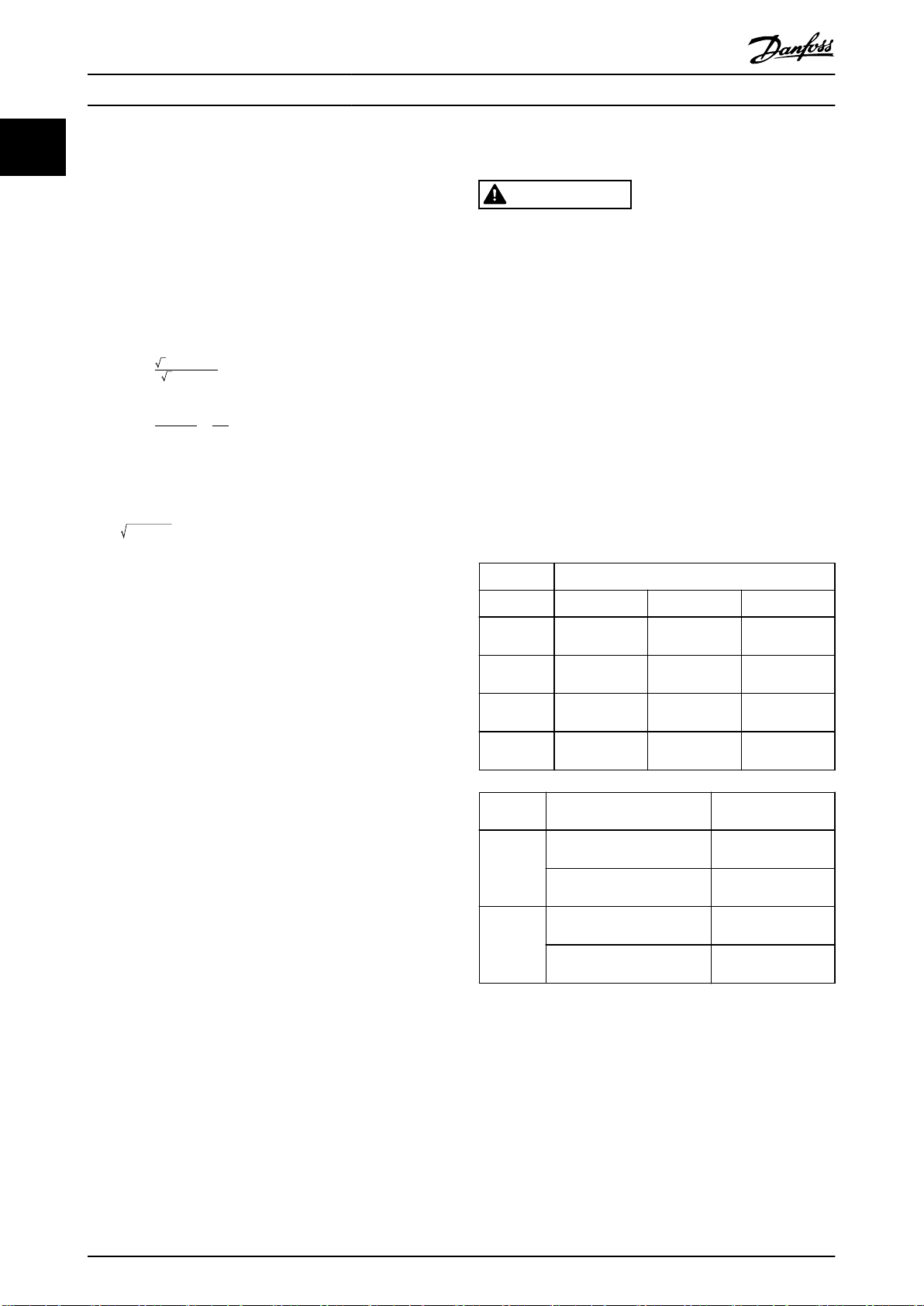
Table 1.1 Software Version
The following symbols are used in this manual.
WARNING
Indicates a potentially hazardous situation which could
result in death or serious injury.
CAUTION
Indicates a potentially hazardous situation which could
result in minor or moderate injury. It may also be used
to alert against unsafe practices.
NOTICE
Indicates important information, including situations that
may result in damage to equipment or property.
60° AVM 60° asynchronous vector modulation
A Ampere/AMP
AC Alternating current
AD Air discharge
AEO Automatic energy optimization
AI Analog input
AIC Ampere interrupting current
AMA Automatic motor adaptation
AWG American wire gauge
°C
CB Circuit breaker
CD Constant discharge
CDM Complete drive module: The frequency converter,
CE European Conformity (European safety standards)
CM Common mode
CT Constant torque
DC Direct current
DI Digital input
Degrees Celsius
feeding section, and auxiliaries
DM Dierential mode
D-TYPE Drive dependent
EMC Electromagnetic compatibility
EMF Electromotive force
ETR Electronic thermal relay
°F
f
JOG
f
M
f
MAX
f
MIN
f
M,N
FC Frequency converter
Hiperface®Hiperface® is a registered trademark by Stegmann
HO High overload
hp Horse power
HTL HTL encoder (10–30 V) pulses - High-voltage
Hz Hertz
I
INV
I
LIM
I
M,N
I
VLT,MAX
I
VLT,N
kHz Kilohertz
LCP Local control panel
lsb Least signicant bit
m Meter
mA Milliampere
MCM Mille circular mil
MCT Motion control tool
mH Inductance in milli Henry
mm Millimeter
ms Millisecond
msb Most signicant bit
η
VLT
nF Capacitance in nano Farad
NLCP Numerical local control panel
Nm Newton meter
NO Normal overload
n
s
Online/
Oine
Parameters
P
br,cont.
PCB Printed circuit board
PCD Process data
Degrees Fahrenheit
Motor frequency when jog function is activated
Motor frequency
Maximum output frequency, the frequency
converter applies on its output
Minimum motor frequency from the frequency
converter
Nominal motor frequency
transistor logic
Rated inverter output current
Current limit
Nominal motor current
Maximum output current
Rated output current supplied by the frequency
converter
Eciency of the frequency converter dened as
ratio between power output and power input
Synchronous motor speed
Changes to online parameters are activated
immediately after the data value is changed
Rated power of the brake resistor (average power
during continuous braking)
4 Danfoss A/S © 05/2016 All rights reserved. MG16H202
Page 7
Introduction Programming Guide
PDS Power drive system: A CDM and a motor
PELV Protective extra low voltage
P
m
P
M,N
PM motor Permanent magnet motor
Process PID PID (proportional integrated dierential) regulator
R
br,nom
RCD Residual current device
Regen Regenerative terminals
R
min
RMS Root mean square
RPM Revolutions per minute
R
rec
s Second
SCCR Short circuit current rating
SFAVM Stator ux-oriented asynchronous vector
STW Status word
SMPS Switch mode power supply
THD Total harmonic distortion
T
LIM
TTL TTL encoder (5 V) pulses - transistor transistor
U
M,N
UL Underwriters Laboratories (US organization for the
V Volts
VT Variable torque
VVC+
Frequency converter nominal output power as
high overload (HO)
Nominal motor power
that maintains the speed, pressure, temperature,
and so on
Nominal resistor value that ensures a brake power
on the motor shaft of 150/160% for 1 minute
Minimum permissible brake resistor value by
frequency converter
Recommended brake resistor resistance of
Danfoss brake resistors
modulation
Torque limit
logic
Nominal motor voltage
safety certication)
Voltage vector control plus
and electrical installation of the frequency
converter.
VLT® Refrigeration Drive FC 103 Design Guide holds
•
all technical information about the frequency
converter, customer design, and applications.
®
Refrigeration Drive FC 103 Programming Guide
VLT
•
provides information on how to program and
includes complete parameter descriptions.
MCT 10 Set-up Software Operating Instructions
•
enables the user to congure the frequency
converter from a Windows™-based PC
environment.
VLT® HVAC Drive FC 102/VLT® AQUA Drive FC 202
•
Metasys N2, Operating Instructions.
1.1 Denitions
1.1.1 Frequency Converter
I
VLT,MAX
Maximum output current.
I
VLT,N
Rated output current supplied by the frequency converter.
U
VLT,MAX
Maximum output voltage.
1.1.2 Input
Control command
Start and stop the connected motor with LCP and digital
inputs.
Functions are divided into 2 groups.
Functions in group 1 have higher priority than functions in
group 2.
1 1
Table 1.2 Abbreviations
Conventions
Numbered lists indicate procedures.
Group 1 Reset, coast stop, reset and coast stop, quick stop,
DC brake, stop, the [OFF] key.
Group 2 Start, pulse start, reversing, start reversing, jog,
freeze output.
Bullet lists indicate other information and description of
illustrations.
Table 1.3 Function Groups
Italicized text indicates:
Cross-reference.
•
Link.
•
Footnote.
•
Parameter name, parameter group name,
•
parameter option.
All dimensions in drawings are in mm (in).
* Indicates a default setting of a parameter.
®
VLT
•
Refrigeration Drive FC 103 Operating
Instructions provides information on mechanical
1.1.3 Motor
Motor running
Torque generated on output shaft and speed from 0 RPM
to maximum speed on motor.
f
JOG
Motor frequency when the jog function is activated (via
digital terminals).
f
M
Motor frequency.
f
MAX
Maximum motor frequency.
MG16H202 Danfoss A/S © 05/2016 All rights reserved. 5
Page 8
175ZA078.10
Pull-out
rpm
Torque
Introduction
VLT® Refrigeration Drive FC 103
11
f
MIN
1.1.4 References
Minimum motor frequency.
f
M,N
Rated motor frequency (nameplate data).
I
M
Motor current (actual).
I
M,N
Rated motor current (nameplate data).
n
M,N
Nominal motor speed (nameplate data).
n
s
Synchronous motor speed.
2 × par . 1 − 23 × 60s
ns=
par . 1 − 39
n
slip
Motor slip.
P
M,N
Rated motor power (nameplate data in kW or hp).
T
M,N
Rated torque (motor).
U
M
Instant motor voltage.
U
M,N
Analog reference
A signal transmitted to the analog inputs 53 or 54 (voltage
or current).
Binary reference
A signal transmitted to the serial communication port.
Preset reference
A dened preset reference to be set from -100% to +100%
of the reference range. Selection of 8 preset references via
the digital terminals.
Pulse reference
A pulse frequency signal transmitted to the digital inputs
(terminal 29 or 33).
Ref
MAX
Determines the relationship between the reference input at
100% full scale value (typically 10 V, 20 mA) and the
resulting reference. The maximum reference value is set in
parameter 3-03 Maximum Reference.
Ref
MIN
Determines the relationship between the reference input at
0% value (typically 0 V, 0 mA, 4 mA) and the resulting
reference. The minimum reference value is set in
parameter 3-02 Minimum Reference.
Rated motor voltage (nameplate data).
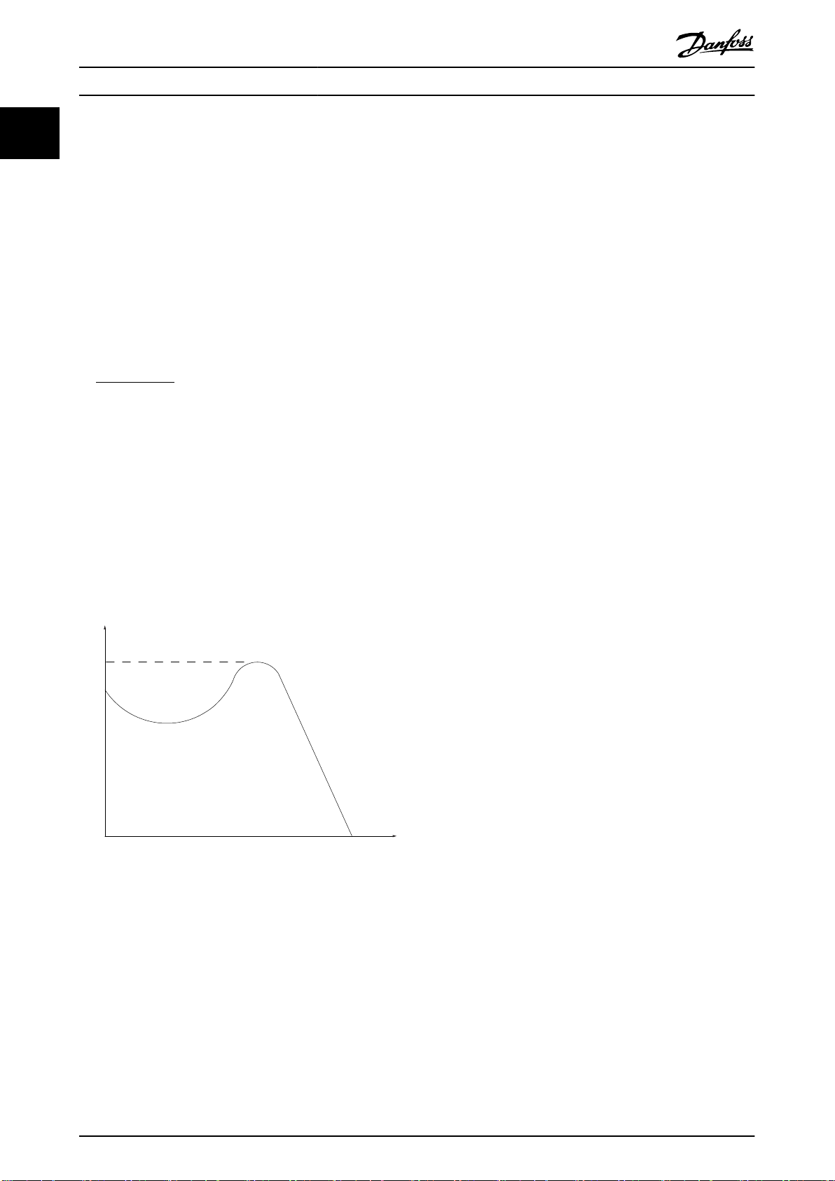
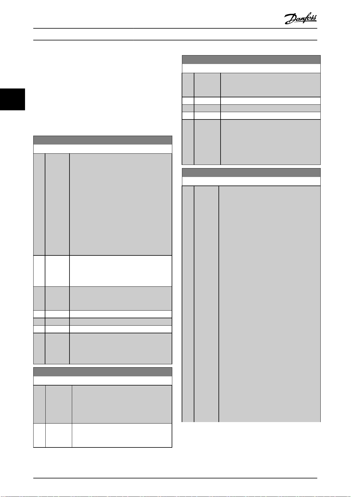
Break-away torque
1.1.5 Miscellaneous
Illustration 1.1 Break-away Torque
η
VLT
The eciency of the frequency converter is dened as the
ratio between the power output and the power input.
Start-disable command
A stop command belonging to Group 1 control commands
- see Table 1.3.
Stop command
A stop command belonging to Group 1 control commands
- see Table 1.3.
Analog inputs
The analog inputs are used for controlling various
functions of the frequency converter.
There are 2 types of analog inputs:
Current input, 0–20 mA, and 4–20 mA
Voltage input, -10 V DC to +10 V DC.
Analog outputs
The analog outputs can supply a signal of 0–20 mA, 4–20
mA.
Automatic motor adaptation, AMA
AMA algorithm determines the electrical parameters for
the connected motor at standstill.
CT characteristics
Constant torque characteristics used for all applications
such as conveyor belts, displacement pumps, and cranes.
Digital inputs
The digital inputs can be used for controlling various
functions of the frequency converter.
Digital outputs
The frequency converter features 2 solid-state outputs that
can supply a 24 V DC (maximum 40 mA) signal.
DSP
Digital signal processor.
6 Danfoss A/S © 05/2016 All rights reserved. MG16H202
Page 9

Introduction Programming Guide
ETR
Electronic thermal relay is a thermal load calculation based
on present load and time. Its purpose is to estimate the
motor temperature.
Hiperface
Hiperface® is a registered trademark by Stegmann.
Initializing
If initializing is carried out (parameter 14-22 Operation
Mode), the frequency converter returns to the default
setting.
Intermittent duty cycle
An intermittent duty rating refers to a sequence of duty
cycles. Each cycle consists of an on-load and an o-load
period. The operation can be either periodic duty or nonperiodic duty.
LCP
The local control panel makes up a complete interface for
control and programming of the frequency converter. The
control panel is detachable and can be installed up to 3 m
(10 ft) from the frequency converter, that is, in a front
panel with the installation kit option.
NLCP
Numerical local control panel interface for control and
programming of the frequency converter. The display is
numerical and the panel is used to show process values.
The NLCP has no storage and copy functions.
lsb
Least signicant bit.
msb
Most signicant bit.
MCM
Short for mille circular mil, an American measuring unit for
cable cross-section. 1 MCM=0.5067 mm2.
Online/oine parameters
Changes to online parameters are activated immediately
after the data value is changed. Press [OK] to activate
changes to o-line parameters.
Process PID
The PID control maintains the required speed, pressure,
temperature, and so on, by adjusting the output frequency
to match the varying load.
PCD
Process control data.
Power cycle
Switch o the mains until display (LCP) is dark – then turn
power on again.
Pulse input/incremental encoder
An external, digital pulse transmitter used for feeding back
information on motor speed. The encoder is used in
applications where great accuracy in speed control is
required.
®
RCD
Residual current device.
Set-up
Save parameter settings in 4 set-ups. Change between the
4 parameter set-ups and edit 1 set-up, while another setup is active.
SFAVM
Switching pattern called stator ux-oriented asynchronous
vector modulation (parameter 14-00 Switching Pattern).
Slip compensation
The frequency converter compensates for the motor slip by
giving the frequency a supplement that follows the
measured motor load keeping the motor speed almost
constant.
SLC
The SLC (smart logic control) is a sequence of user-dened
actions executed when the associated user-dened events
are evaluated as true by the SLC. (See
chapter 3.11 Parameters: 13-** Smart Logic).
STW
Status word.
FC standard bus
Includes RS485 bus with FC protocol or MC protocol. See
parameter 8-30 Protocol.
THD
Total harmonic distortion states the total contribution of
harmonic.
Thermistor
A temperature-dependent resistor placed on the frequency
converter or the motor.
Trip
A state entered in fault situations, for example if the
frequency converter is subject to an overtemperature or
when the frequency converter is protecting the motor,
process, or mechanism. The frequency converter prevents a
restart until the cause of the fault has disappeared. To
cancel the trip state, restart the frequency converter. Do
not use the trip state for personal safety.
Trip lock
The frequency converter enters this state in fault situations
to protect itself. The frequency converter requires physical
intervention, for example when there is a short circuit on
the output. A trip lock can only be canceled by disconnecting mains, removing the cause of the fault, and
reconnecting the frequency converter. Restart is prevented
until the trip state is canceled by activating reset or,
sometimes, by being programmed to reset automatically.
Do not use the trip lock state for personal safety.
VT characteristics
Variable torque characteristics used for pumps and fans.
1 1
MG16H202 Danfoss A/S © 05/2016 All rights reserved. 7
Page 10
Introduction
VLT® Refrigeration Drive FC 103
11
VVC
+
1.2
Safety
If compared with standard voltage/frequency ratio control,
voltage vector control (VVC+) improves the dynamics and
the stability, both when the speed reference is changed
and in relation to the load torque.
60° AVM
60° asynchronous vector modulation
(parameter 14-00 Switching Pattern).
Power factor
The power factor is the relation between I1 and I
Power factor =
3xUxI1cosϕ
3xUxI
RMS
RMS
.
The power factor for 3-phase control:
Power factor =
I1xcosϕ1
I
RMS
=
I
RMS
I
1
sincecosϕ1 = 1
The power factor indicates to which extent the frequency
converter imposes a load on the mains supply.
The lower the power factor, the higher the I
RMS
for the
same kW performance.
2
2
2
I
= I
+ I
RMS
+ I
1
5
+ .. + I
7
2
n
WARNING
DISCHARGE TIME
The frequency converter contains DC-link capacitors,
which can remain charged even when the frequency
converter is not powered. High voltage can be present
even when the warning indicator lights are o. Failure to
wait the specied time after power has been removed
before performing service or repair work, could result in
death or serious injury.
1. Stop the motor.
2. Disconnect AC mains, permanent magnet type
motors, and remote DC-link power supplies,
including battery back-ups, UPS, and DC-link
connections to other frequency converters.
3. Wait for the capacitors to discharge fully, before
performing any service or repair work. The
duration of waiting time is specied in Table 1.4.
In addition, a high-power factor indicates that the dierent
harmonic currents are low.
Voltage [V] Minimum waiting time (minutes)
The DC coils in the frequency converters produce a highpower factor, which minimizes the imposed load on the
mains supply.
Target position
The nal target position specied by positioning
commands. The prole generator uses this position to
calculate the speed prole.
Commanded position
The actual position reference calculated by the prole
generator. The frequency converter uses the commanded
4 7 15
200–240 0.25–3.7 kW
(0.34–5 hp)
380–500 0.25–7.5 kW
(0.34–10 hp)
525–600 0.75–7.5 kW
(1–10 hp)
525–690 – 1.5–7.5 kW
– 5.5–37 kW
(7.5–50 hp)
– 11–75 kW
(15–100 hp)
– 11–75 kW
(15–100 hp)
(2–10 hp)
(15–100 hp)
11–75 kW
position as setpoint for position PI.
Actual position
The actual position from an encoder, or a value that the
motor control calculates in open loop. The frequency
converter uses the actual position as feedback for position
PI.
Position error
Position error is the dierence between the actual position
and the commanded position. The position error is the
input for the position PI controller.
Position unit
The physical unit for position values.
Voltage
[V]
380–500 90–250 kW
525–690 55–315 kW (frame size D)
Table 1.4 Discharge Time
Power Minimum waiting
time (minutes)
20
(125–350 hp)
315–800 kW
(450–1075 hp)
(75–450 hp)
355–1200 kW
(475–1600 hp)
40
20
30
Safety regulations
Disconnect mains supply to the frequency
•
converter whenever repair work is to be carried
out. Check that the mains supply has been
disconnected and that the necessary time has
elapsed before removing motor and mains supply
8 Danfoss A/S © 05/2016 All rights reserved. MG16H202
Page 11

Introduction Programming Guide
plugs. For information about the discharge time,
see Table 1.4.
[O] does not disconnect the mains supply and
•
must not be used as a safety switch.
Ground the equipment properly, protect the user
•
against supply voltage, and protect the motor
against overload in accordance with applicable
national and local regulations.
The ground leakage current exceeds 3.5 mA.
•
Ensure correct grounding of the equipment by a
certied electrical installer.
Do not remove the plugs for the motor and
•
mains supply while the frequency converter is
connected to mains. Check that the mains supply
has been disconnected and that the necessary
time has elapsed before removing motor and
mains plugs.
The frequency converter has more voltage
•
sources than L1, L2, and L3, when load sharing
(linking of DC intermediate circuit) or external 24
V DC is installed. Check that all voltage sources
have been disconnected and that the necessary
time has elapsed before commencing repair work.
For information about the discharge time, see
Table 1.4.
NOTICE
When using the Safe Torque O, always follow the
instructions in VLT® Frequency Converters - Safe Torque
O Operating Instructions.
NOTICE
Hazardous situations must be identied by the machine
builder/integrator who is responsible for considering the
necessary preventive means. More monitoring and
protective devices may be included, always according to
valid national safety regulations, for example, law on
mechanical tools and regulations for the prevention of
accidents.
Protection mode
Once a hardware limit on motor current or DC-link voltage
is exceeded, the frequency converter enters the protection
mode. Protection mode means a change of the PWM
modulation strategy and a low switching frequency to
minimize losses. This continues for 10 s after the last fault
and increases the reliability and the robustness of the
frequency converter while re-establishing full control of the
motor.
Protection mode can be disabled by setting
parameter 14-26 Trip Delay at Inverter Fault to 0, which
means that the frequency converter trips immediately if 1
of the hardware limits is exceeded.
NOTICE
Disabling protection mode in hoisting applications
(parameter 14-26 Trip Delay at Inverter Fault = 0) is
recommended.
1 1
NOTICE
Control signals from, or internally within, the frequency
converter may in rare cases be activated in error, be
delayed, or fail to occur entirely. When used in situations
where safety is critical, for example, when controlling the
electromagnetic brake function of a hoist application,
these control signals must not be relied on exclusively.
MG16H202 Danfoss A/S © 05/2016 All rights reserved. 9
Page 12
*
91 (L1)
92 (L2)
93 (L3)
PE
88 (-)
89 (+)
50 (+10 V OUT)
53 (A IN)
54 (A IN)
55 (COM A IN)
0/4–20 mA
12 (+24 V OUT)
13 (+24 V OUT)
18 (D IN)
20 (COM D IN)
15 mA 200 mA
(U) 96
(V) 97
(W) 98
(PE) 99
(COM A OUT) 39
(A OUT) 42
0/4–20 mA
03
0–10 V DC
+10 V DC
0-10 V DC
0/4–20 mA
240 V AC, 2 A
24 V DC
02
01
05
04
06
240 V AC, 2 A
24 V (NPN)
0 V (PNP)
0 V (PNP)
24 V (NPN)
19 (D IN)
24 V (NPN)
0 V (PNP)
27
24 V
0 V
(D IN/OUT)
0 V (PNP)
24 V (NPN)
(D IN/OUT)
0 V
24 V
29
24 V (NPN)
0 V (PNP)
0 V (PNP)
24 V (NPN)
33 (D IN)
32 (D IN)
1 2
ON
S201
ON
21
S202
ON=0–20 mA
OFF=0–10 V
95
400 V AC, 2 A
P 5-00
(R+) 82
(R-) 81
37 (D IN)
+ - + -
130BA544.13
(P RS485) 68
(N RS485) 69
(COM RS485) 61
0V
5 V
S801
RS485
RS485
21
ON
S801
3-phase
power
input
DC bus
Switch mode
power supply
Motor
Analog output
Interface
Relay1
Relay2
ON=Terminated
OFF=Open
Brake
resistor
(NPN) = Sink
(PNP) = Source
Introduction
VLT® Refrigeration Drive FC 103
11
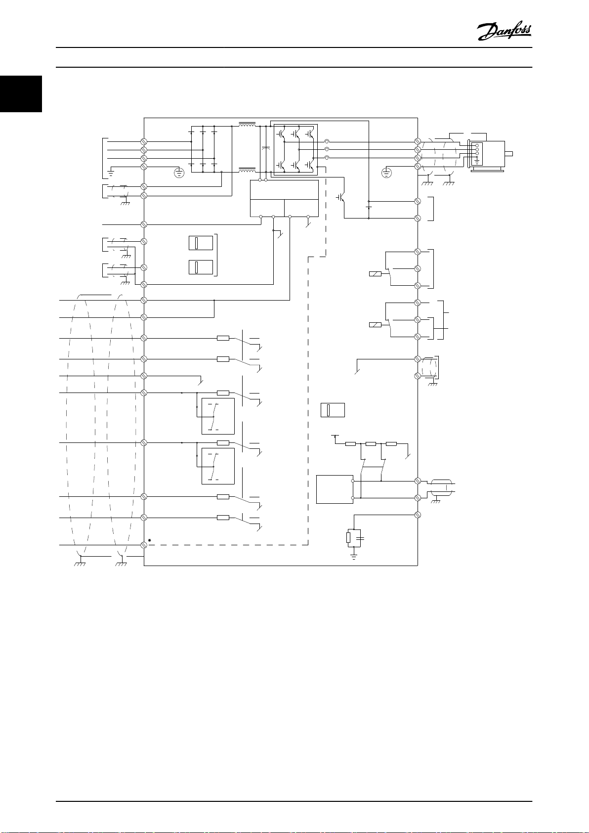
1.3 Electrical Wiring
Illustration 1.2 Basic Wiring Schematic Drawing
A=Analog, D=Digital
Terminal 37 is used for Safe Torque O. For Safe Torque O installation instructions, refer to the VLT® Frequency Converters -
Safe Torque O Operating Instructions.
Very long control cables and analog signals may in rare cases, and depending on installation, result in 50/60 Hz ground
loops due to noise from mains supply cables.
If this occurs, it may be necessary to break the shield or insert a 100 nF capacitor between shield and enclosure.
Connect the digital and analog inputs and outputs separately to the common inputs (terminals 20, 55, and 39) of the
frequency converter to avoid ground currents from both groups to
digital input may disturb the analog input signal.
10 Danfoss A/S © 05/2016 All rights reserved. MG16H202
aect other groups. For example, switching on the
Page 13
12 13 18 19 27 29 32 33 20 37
+24 VDC
0 VDC
130BT106.10
PNP (Source)
Digital input wiring
NPN (Sink)
Digital input wiring
12 13 18 19 27 29 32 33 20 37
+24 VDC
0 VDC
130BT107.11
130BA681.10
12 13 18 37
130BA155.12
322719 29 33 20
P 5-12 [0]
P 5-10 [8]
Start/Stop
+24V
Speed
Safe Stop
Start/Stop
[18]
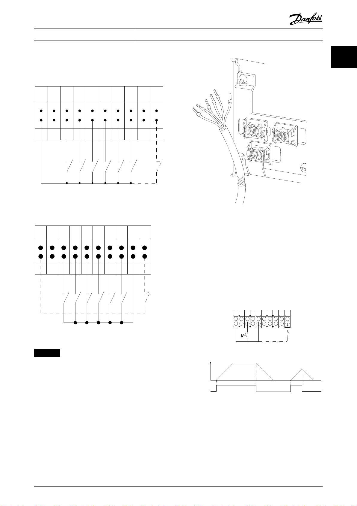
Introduction Programming Guide
Input polarity of control terminals
Illustration 1.3 PNP (Source)
1 1
Illustration 1.5 Grounding of Shielded/Armored Control Cables
Illustration 1.4 NPN (Sink)
NOTICE
Use shielded/armored control cables.
1.3.1 Start/Stop
Terminal 18 = parameter 5-10 Terminal 18 Digital Input [8]
Start.
Terminal 27 = parameter 5-12 Terminal 27 Digital Input [0]
No operation (Default [2] Coast inverse).
Terminal 37 = Safe Torque O (where available).
Illustration 1.6 Start/Stop
MG16H202 Danfoss A/S © 05/2016 All rights reserved. 11
Page 14
12 13 18 37
130BA156.12
322719 29 33 20
P 5 - 12 [6]
P 5 - 10[9]
+24V
Speed
Start Stop inverse Safe Stop
Start (18)
Start (27)
12
18
27
29
32
37
+24V
Par. 5-10
Par. 5-12
Par. 5-13
Par. 5-14
130BA021.12
130BA154.11
555039 42 53 54
Speed RPM
P 6-15
1 kΩ
+10V/30mA
Ref. voltage
P 6-11 10V
Introduction
VLT® Refrigeration Drive FC 103
11
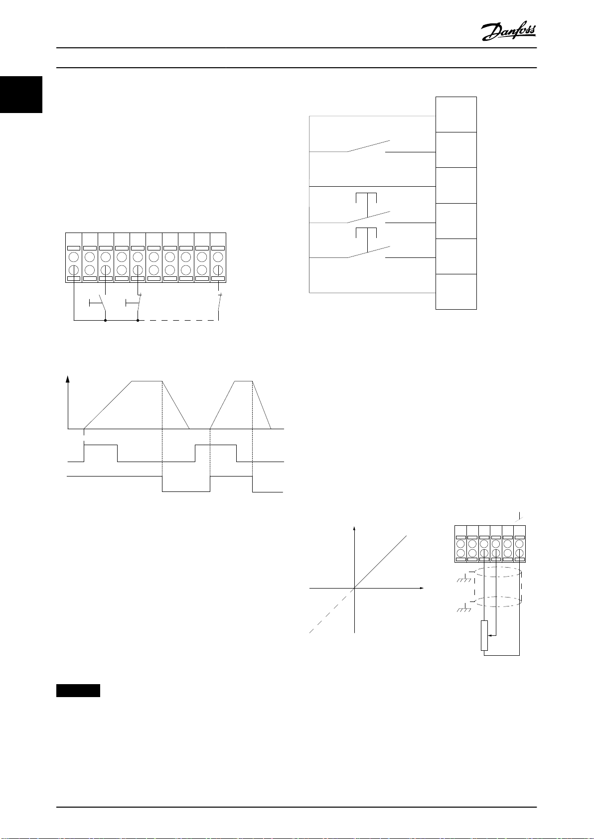
1.3.2 Pulse Start/Stop
Terminal 18 = parameter 5-10 Terminal 18 Digital Input, [9]
Latched start.
Terminal 27 = parameter 5-12 Terminal 27 Digital Input, [6]
Stop inverse.
Terminal 37 = Safe Torque O (where available).
Illustration 1.8 Speed up/Speed down
1.3.4 Potentiometer Reference
Voltage reference via a potentiometer
Reference source 1 = [1] Analog input 53 (default).
Terminal 53, low voltage = 0 V.
Terminal 53, high voltage = 10 V.
Terminal 53, low reference/feedback = 0 RPM.
Terminal 53, high reference/feedback = 1500 RPM.
Switch S201 = OFF (U)
Illustration 1.7 Pulse Start/Stop
1.3.3 Speed up/Speed Down
Terminals 29/32 = Speed up/Speed down
Terminal 18 = Parameter 5-10 Terminal 18 Digital
Input [9] Start (default).
Terminal 27 = Parameter 5-12 Terminal 27 Digital
Input [19] Freeze reference.
Terminal 29 = Parameter 5-13 Terminal 29 Digital
Input [21] Speed up.
Terminal 32 = Parameter 5-14 Terminal 32 Digital
Input [22] Speed down.
NOTICE
Terminal 29 only in FC x02 (x=series type).
Illustration 1.9 Potentiometer Reference
12 Danfoss A/S © 05/2016 All rights reserved. MG16H202
Page 15
Auto
on
Reset
Hand
on
O
Status
Quick
Menu
Main
Menu
Alarm
Log
Back
Cancel
Info
OK
Status
1(0)
1234rpm 10,4A 43,5Hz
Run OK
43,5Hz
On
Alarm
Warn.
130BA018.13
1
2
3
4
b
a
c
How to Program Programming Guide
2 How to Program
2.1 Local Control Panel
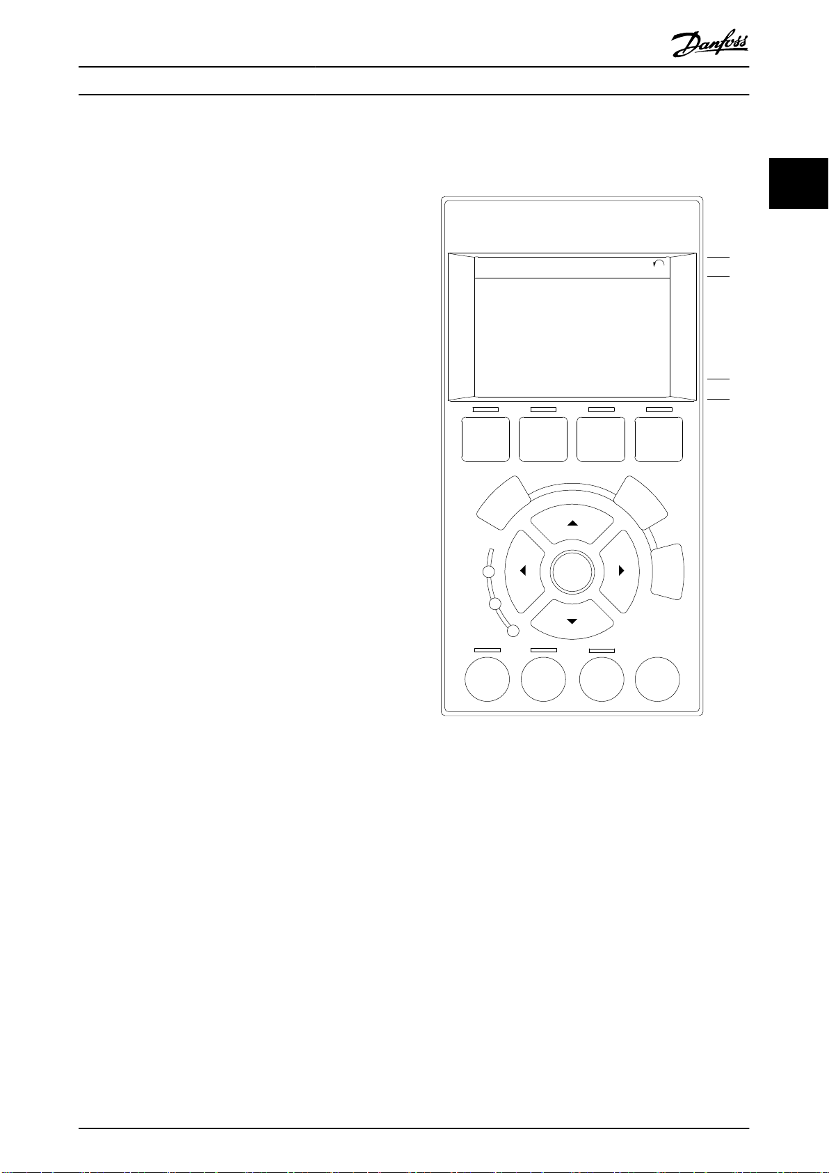
2.1.1 How to Operate Graphical LCP (GLCP)
The GLCP is divided into 4 functional groups:
1. Graphical display with status lines.
2. Menu keys and indicator lights (LEDs) - selecting
mode, changing parameters, and switching
between display functions.
3. Navigation keys and indicator lights (LEDs).
4. Operation keys and indicator lights (LEDs).
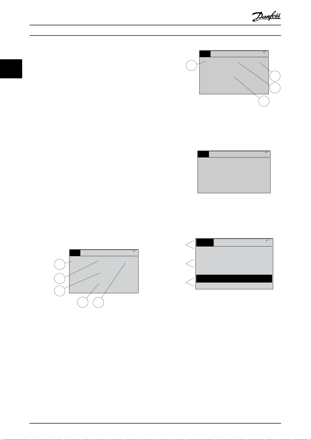
Graphical display
The LCD display is backlit with a total of 6 alpha-numeric
lines. All data is shown on the LCP, which can show up to
5 operating variables while in Status mode.
Display lines:
a. Status line
Status messages displaying icons and graphics.
b. Line 1–2
Operator data lines displaying data and variables
dened or selected by the user. Press [Status] to
add 1 extra line.
c. Status line
Status messages displaying text.
2 2
Illustration 2.1 LCP
The display is divided into 3 sections:
Top section
(a) shows the status when in Status mode, or up to 2
variables when not in Status mode, and in the case of
alarm/warning.
The number of the active set-up (selected as the active
set-up in parameter 0-10 Active Set-up) is shown. When
programming in another set-up than the active set-up, the
number of the set-up being programmed appears to the
right in brackets.
Middle section
(b) shows up to 5 variables with related unit, regardless of
status. In case of alarm/warning, the warning is shown
instead of the variables.
Bottom section
(c) always shows the state of the frequency converter in
status mode.
Press [Status] to toggle between 3 status readout displays.
MG16H202 Danfoss A/S © 05/2016 All rights reserved. 13
Page 16
1.1
2
3
1.3
1.2
130BP041.10
799 RPM
Auto Remote Ramping
1 (1)
36.4 kw7.83 A
0.000
53.2 %
Status
1.1
1.2
2
1.3
130BP062.10
207RPM
Auto Remote Running
1 (1)
24.4 kW5.25A
6.9
Hz
Status
130BP063.10
778 RPM
Auto Remote Running
1 (1)
4.0 kW0.86 A
State: 0 o 0 (o)
When: Do: -
Status
Top section
Middle section
Bottom section
Status
43 RPM
1.4 Hz
Auto Remote Running
! Pwr.card temp (W29)
2.9%
5.44 A 25.3kW
1(1)
130BP074.10
!
How to Program
VLT® Refrigeration Drive FC 103
Operating variables with dierent formatting are shown in
each status screen.
22
Several values or measurements can be linked to each of
the shown operating variables.
Dene the values/measurements to be shown via:
Parameter 0-20 Display Line 1.1 Small
•
Parameter 0-21 Display Line 1.2 Small
•
Parameter 0-22 Display Line 1.3 Small
•
Parameter 0-23 Display Line 2 Large
•
Parameter 0-24 Display Line 3 Large
•
which can be accessed via [Quick Menu], Q3 Function Setups, Q3-1 General Settings, Q3-13 Display Settings.
Each value/measurement readout parameter selected in
Illustration 2.3 Example of Status Display II
Status display III
This state displays the event and action of the smart logic
control.
parameter 0-20 Display Line 1.1 Small to
parameter 0-24 Display Line 3 Large has its own scale and
number of digits after a possible decimal point. Larger
numeric values are shown with few digits after the decimal
point.
Ex.: Current readout
5.25 A; 15.2 A 105 A.
Status display I
Illustration 2.4 Example of Status Display III
This readout state is standard after start-up or initialization.
Press [INFO] to obtain information about the value/
measurement linked to the shown operating variables (1.1,
1.2, 1.3, 2, and 3).
See the operating variables shown in the display in
Display contrast adjustment
Press [Status] and [▲] for darker display.
Press [Status] and [▼] for brighter display.
Illustration 2.2. 1.1, 1.2, and 1.3 are shown in small size. 2
and 3 are shown in medium size.
Illustration 2.5 Display Sections
Illustration 2.2 Example of Status Display I
Indicator lights (LEDs)
If certain threshold values are exceeded, the alarm and/or
warning LED lights up. A status and alarm text appear in
Status display II
See the operating variables (1.1, 1.2, 1.3, and 2) shown in
the display in Illustration 2.3.
In the example, speed, motor current, motor power, and
frequency are selected as variables in the rst and second
lines.
1.1, 1.2, and 1.3 are shown in small size. 2 is shown in
large size.
14 Danfoss A/S © 05/2016 All rights reserved. MG16H202
the display.
The On LED is activated when the frequency converter
receives power from mains voltage, a DC bus terminal, or a
24 V external supply. At the same time, the backlight is on.
Green LED/On: Control section is working.
•
Yellow LED/Warn.: Indicates a warning.
•
Flashing Red LED/Alarm: Indicates an alarm.
•
Page 17

On
Warn.
Alarm
130BP044.10
130BP045.10
Status
Quick
Menu
Main
Menu
Alarm
Log
How to Program Programming Guide
Illustration 2.6 Indicator Lights
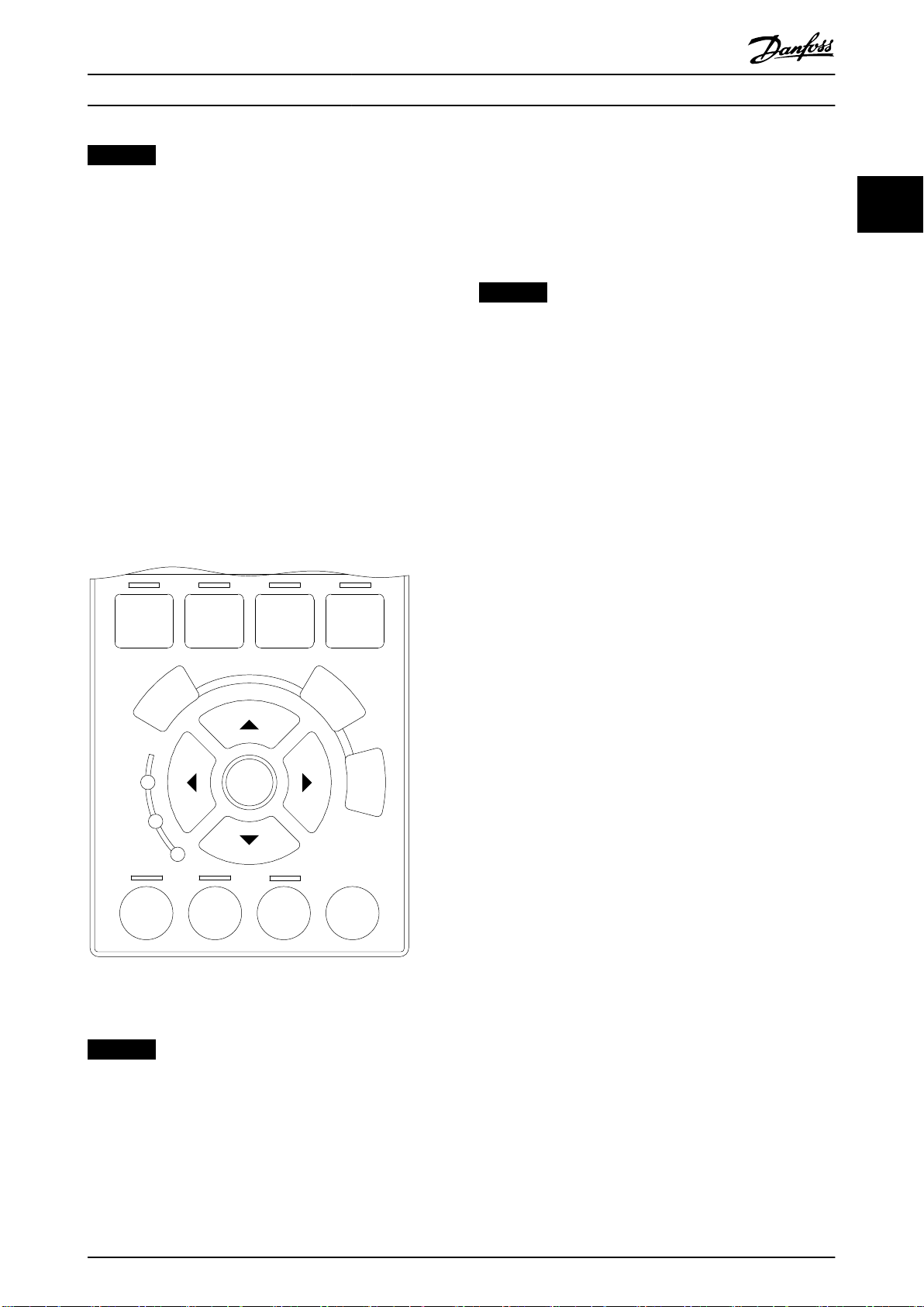
GLCP keys
Menu keys
The menu keys are divided into functions. The keys below
the display and indicator lights are used for parameter setup, including selection of display indication during normal
operation.
Illustration 2.7 Menu Keys
Most VAV and CAV supply and return fans.
•
Cooling tower fans.
•
Primary, secondary, and condenser water pumps.
•
Other pump, fan, and compressor applications.
•
Among other features, it also includes parameters for
selecting which variables to display in the LCP:
Digital preset speeds.
•
Scaling of analog references.
•
Closed-loop single-zone and multi-zone
•
applications.
Specic functions related to fans, pumps, and
•
compressors.
The Quick Menu parameters can be accessed immediately
unless a password has been created via:
Parameter 0-60 Main Menu Password.
•
Parameter 0-61 Access to Main Menu w/o Password.
•
Parameter 0-65 Personal Menu Password.
•
Parameter 0-66 Access to Personal Menu w/o
•
Password.
It is possible to switch directly between Quick Menu mode
and Main Menu mode.
2 2
[Status]
[Status] indicates the status of the frequency converter
and/or the motor.
3 dierent readouts can be selected by pressing the
[Status] key:
5-line readouts.
•
4-line readouts.
•
Smart logic control.
•
Press [Status] to select the display mode or for changing
back to Display mode from either Quick Menu mode, Main
Menu mode, or Alarm mode. Also press [Status] to toggle
between single or double readout mode.
[Quick Menu]
[Quick Menu] allows quick set-up of the frequency
converter. The most common functions can be
programmed here.
The Quick Menu consists of:
My personal menu.
•
Quick set-up.
•
Function set-up.
•
Changes made.
•
Loggings.
•
The Function Set-up provides quick and easy access to all
parameters required for most applications including:
[Main Menu]
Press [Main Menu] to program all parameters. The main
menu parameters can be accessed immediately unless a
password has been created via:
Parameter 0-60 Main Menu Password.
•
Parameter 0-61 Access to Main Menu w/o Password.
•
Parameter 0-65 Personal Menu Password.
•
Parameter 0-66 Access to Personal Menu w/o
•
Password.
For most applications, it is not necessary to access the
main menu parameters. Instead, the Quick Menu, Quick Set-
up and Function Set-up provide the simplest and quickest
access to the most required parameters.
It is possible to switch directly between Main Menu mode
and Quick Menu mode.
Parameter shortcut can be carried out by pressing [Main
Menu] for 3 s. The parameter shortcut allows direct access
to any parameter.
[Alarm Log]
[Alarm Log] displays an alarm list of the 10 most recent
alarms (numbered A1-A10). To obtain more details about
an alarm, press the navigation keys to manoeuvre to the
alarm number and press [OK]. Information is shown about
the condition of the frequency converter before it enters
the alarm mode.
The [Alarm Log] key on the LCP allows access to both
alarm log and maintenance log.
MG16H202 Danfoss A/S © 05/2016 All rights reserved. 15
Page 18

B
a
c
k
C
a
n
c
e
l
I
n
f
o
130BT117.10
OK
Back
Info
Warn
Alarm
On
Cancel
130BP046.10
Hand
on
O
Auto
on
Reset
How to Program
VLT® Refrigeration Drive FC 103
[Back]
[Back] reverts to the previous step or layer in the
navigation structure.
Operation keys
Operation keys for local control are found at the bottom of
the control panel.
22
Illustration 2.8 Back Key
Illustration 2.12 Operation Keys
[Cancel]
[Cancel] cancels the last change or command as long as
the display has not been changed.
Illustration 2.9 Cancel Key
[Info]
[Info] displays information about a command, parameter,
or function in any display window. [Info] provides detailed
information when needed.
Exit Info mode by pressing either [Info], [Back], or [Cancel].
Illustration 2.10 Info Key
[Hand On]
[Hand On] enables control of the frequency converter via
the GLCP. [Hand On] also starts the motor and allows
entering the motor speed data with the navigation keys.
The key can be selected as [1] Enable or [0] Disable via
parameter 0-40 [Hand on] Key on LCP.
The following control signals are still active when [Hand
On] is activated:
[Hand On] - [O] - [Auto On].
•
Reset.
•
Coasting stop inverse.
•
Reversing.
•
Set-up select lsb - Set-up select msb.
•
Stop command from serial communication.
•
Quick stop.
•
DC brake.
•
Navigation Keys
The 4 navigation keys are used to navigate between the
dierent options available in the Quick Menu, Main Menu,
and Alarm Log. Press the keys to move the cursor.
[OK]
Press [OK] to select a parameter marked by the cursor and
for enabling the change of a parameter.
Illustration 2.11 Navigation Keys
NOTICE
External stop signals activated with control signals or a
eldbus override a start command via the LCP.
[O]
[O] stops the connected motor. The key can be selected
as [1] Enabled or [0] Disabled via parameter 0-41 [O] Key on
LCP. If no external stop function is selected, and the [O]
key is inactive, the motor can only be stopped by disconnecting the mains supply.
[Auto On]
[Auto On] enables the frequency converter to be controlled
via the control terminals and/or serial communication.
When a start signal is applied on the control terminals
and/or the bus, the frequency converter starts. The key can
be selected as [1] Enabled or [0] Disabled via
parameter 0-42 [Auto on] Key on LCP.
16 Danfoss A/S © 05/2016 All rights reserved. MG16H202
Page 19
Auto
on
Reset
Hand
on
O
Status
Quick
Menu
Main
Menu
Alarm
Log
Back
Cancel
Info
OK
On
Alarm
Warn.
130BA027.10
How to Program Programming Guide
NOTICE
An active HAND-OFF-AUTO signal via the digital inputs
has higher priority than the control keys [Hand On] –
[Auto On].
[Reset]
Press [Reset] to reset the frequency converter after an
alarm (trip). It can be selected as [1] Enable or [0] Disable
via parameter 0-43 [Reset] Key on LCP.
The parameter shortcut can be carried out by pressing the
[Main Menu] key for 3 s. The parameter shortcut allows
direct access to any parameter.
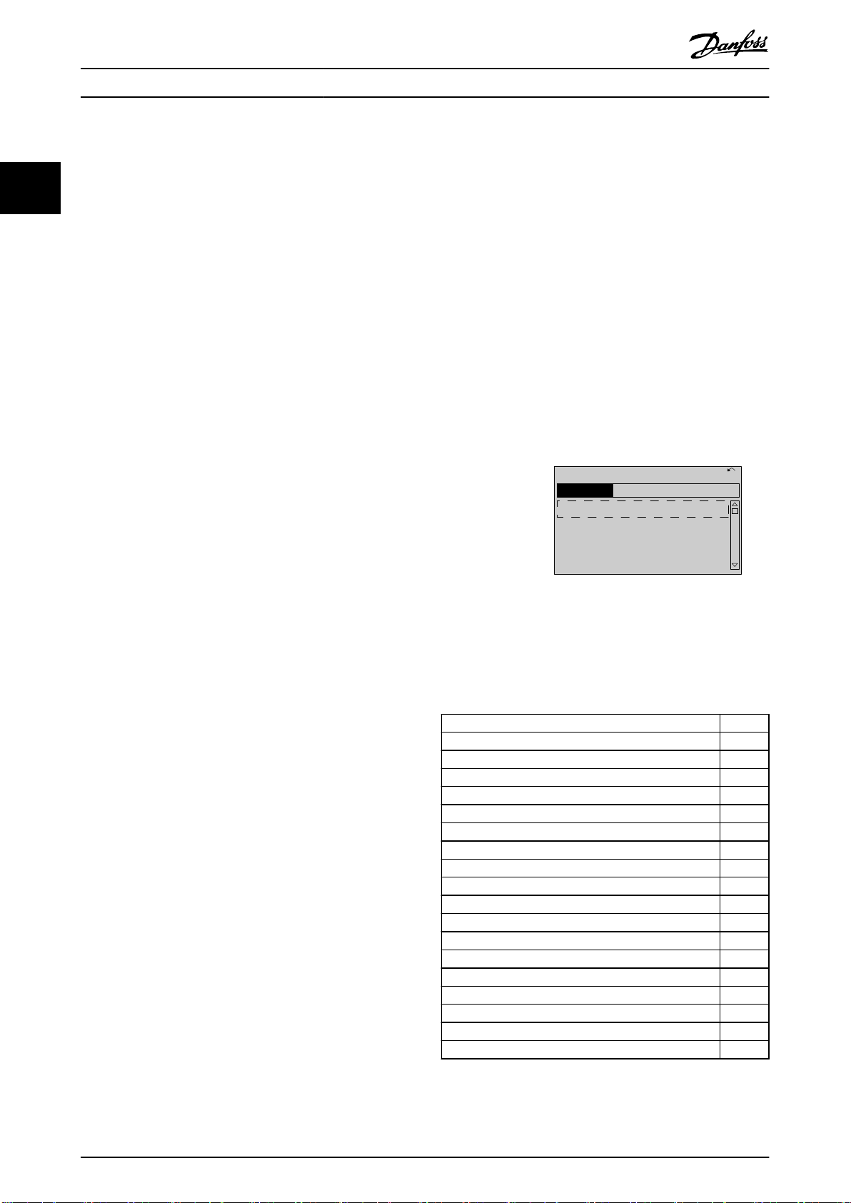
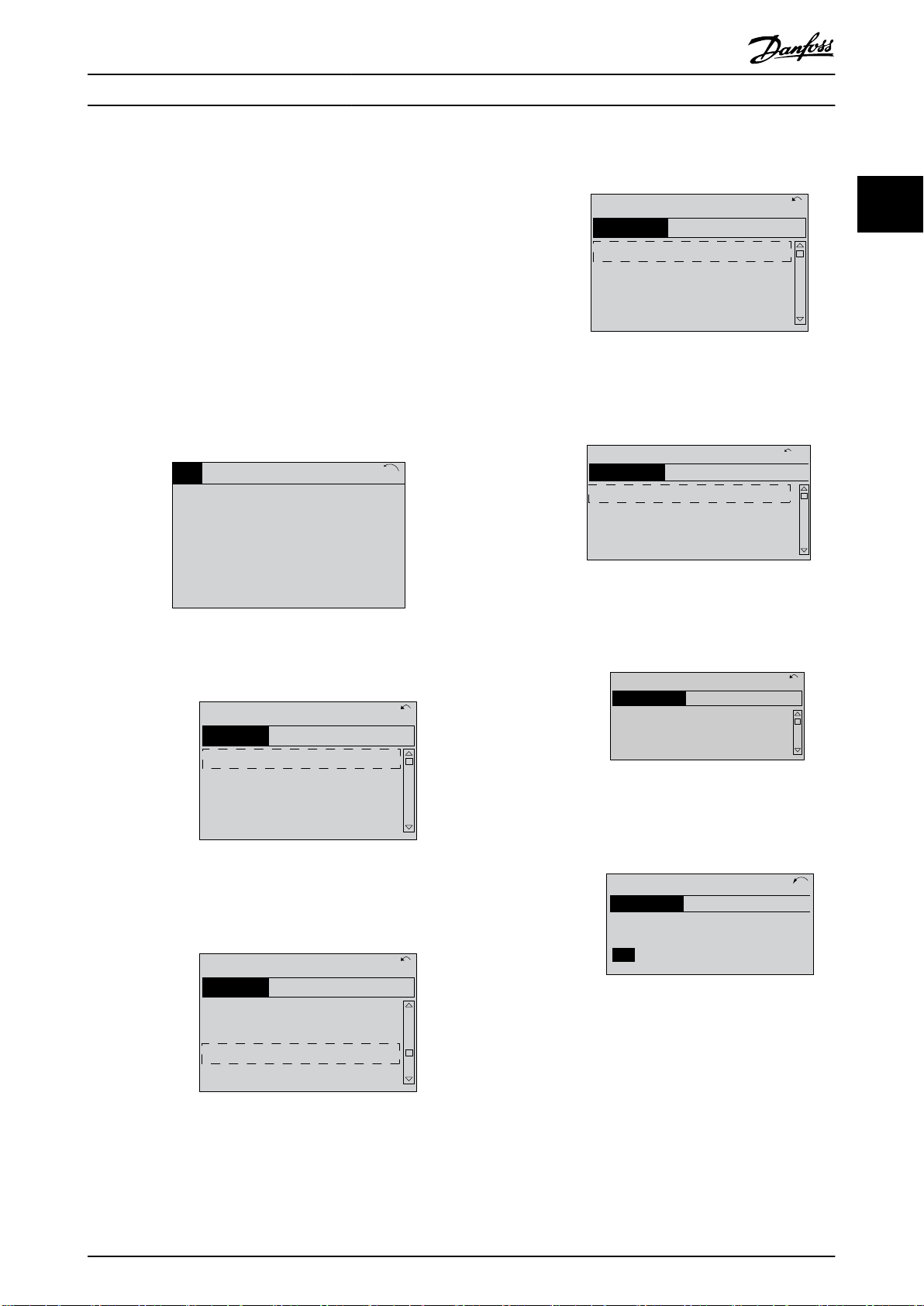
2.1.2 Quick Transfer of Parameter Settings
between Multiple Frequency
Converters
Once the set-up of a frequency converter is complete,
store the data in the LCP or on a PC via MCT 10 Set-up
Software.
All parameter settings are now stored in the LCP indicated
by the progress bar. When 100% is reached, press [OK].
Connect the LCP to another frequency converter and copy
the parameter settings to this frequency converter as well.
Data transfer from LCP to frequency converter
NOTICE
Stop the motor before performing this operation.
To transfer the data from the LCP to the frequency
converter:
1. Go to parameter 0-50 LCP Copy.
2. Press the [OK] key.
3. Select [2] All from LCP.
4. Press the [OK] key.
The parameter settings stored in the LCP are now
transferred to the frequency converter indicated by the
progress bar. When 100% is reached, press [OK].
2.1.3 Parameter Set-Up
The frequency converter can be used for practically all
assignments, thus oering a signicant number of
parameters. The series oers a choice between 2
programming modes - the Quick Menu mode and the Main
Menu mode.
The Main Menu provides access to all parameters. The
Quick Menu takes the user through a few parameters
making it possible to program the majority of applications.
Regardless of the programming mode, parameters can be
changed in both Quick Menu mode and in Main Menu
mode.
2 2
2.1.4 Quick Menu Mode
Parameter data
The graphical display (GLCP) provides access to all
parameters listed in the Quick Menu. The numeric display
(NLCP) only provides access to the Quick Set-up parameters.
To set parameters pressing [Quick Menu] - enter or change
Illustration 2.13 LCP
Data storage in LCP
NOTICE
Stop the motor before performing this operation.
To store the data in the LCP:
1. Go to parameter 0-50 LCP Copy.
2. Press the [OK] key.
3. Select [1] All to LCP.
4. Press the [OK] key.
MG16H202 Danfoss A/S © 05/2016 All rights reserved. 17
parameter data or settings in accordance with the
following procedure:
1. Press [Quick Menu].
2.
Press [▲] or [▼] to nd the parameter to change.
3. Press [OK].
4.
Press [▲] or [▼] to select the correct parameter
setting.
5. Press [OK].
6. To move to a dierent digit within a parameter
setting, use the [◀] and [▶].
Page 20
130BP064.10
Q1 My Personal Menu
Q2 Quick Setup
Q3 Function Setups
Q5 Changes Made
40.0% 4.84 A 1(1)
Quick Menus
How to Program
VLT® Refrigeration Drive FC 103
7. Highlighted area indicates digit selected for
change.
22
8. Press [Cancel] to disregard change, or press [OK]
to accept change and enter the new setting.
Example of changing parameter data
Assume that parameter 22-60 Broken Belt Function is set to
[0] O. To monitor the fan-belt condition, non-broken or
broken, follow this procedure:
1. Press [Quick Menu].
2.
Press [▼] to select Function Set-ups.
3. Press [OK].
4.
Press [▼] to select Application Settings.
5. Press [OK].
6. Press [OK] again for Fan Functions.
7. Press [OK] to select Broken Belt Function.
8.
Press [▼], to select [2] Trip.
Example of using the quick set-up
To set the ramp-down time to 100 s, follow this procedure:
1. Select Quick Set-up. Parameter 0-01 Language in
Quick Set-up appears.
2.
Press [▼] repeatedly until parameter 3-42 Ramp 1
Ramp Down Time appears with the default setting
of 20 s.
3. Press [OK].
4.
Press [◀] to highlight the third digit before the
comma.
5.
Change 0 to 1 by pressing [▲].
6.
Press [▶] to highlight the digit 2.
7.
Change 2 to 0 by pressing [▼].
8. Press [OK].
The new ramp-down time is now set to 100 s.
If a broken fan belt is detected, the frequency converter
trips.
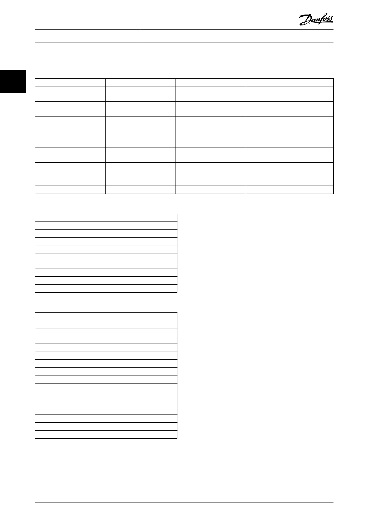
Select Q1 My Personal Menu to display personal
parameters
For example, an AHU or pump OEM may have preprogrammed personal parameters to be in My Personal
Illustration 2.14 Quick Menu View
Menu during factory commissioning to make on-site
commissioning/ne-tuning simpler. These parameters are
selected in parameter 0-25 My Personal Menu. Up to 20
dierent parameters can be programmed in this menu.
Select Changes Made for information about:
The last 10 changes. Press [▲] and [▼] to scroll
•
between the last 10 changed parameters.
The changes made since default setting.
•
Loggings
Loggings show information about the display line
readouts. The information is shown as graphs.
Only display parameters selected in parameter 0-20 Display
Line 1.1 Small and parameter 0-24 Display Line 3 Large can
be viewed. Up to 120 samples can be stored in the
memory for later reference.
Quick set-up
Ecient parameter set-up for refrigeration applications
The parameters can easily be set up for most refrigeration
applications only by using the Quick Set-up.
After pressing [Quick Menu], the dierent options in the
Quick Menu are listed. See also Illustration 2.14.
Access the 18 most important set-up parameters of the
frequency converter via Quick Set-up. After programming,
the frequency converter is ready for operation. The 18
Quick Set-up parameters are shown in Table 2.1.
Parameter [Units]
Parameter 0-01 Language –
Parameter 1-03 Torque Characteristics –
Parameter 1-20 Motor Power [kW ] [kW]
Parameter 1-21 Motor Power [HP] [hp]
Parameter 1-22 Motor Voltage [V]
Parameter 1-23 Motor Frequency [Hz]
Parameter 1-24 Motor Current [A]
Parameter 1-25 Motor Nominal Speed [RPM]
Parameter 1-39 Motor Poles –
Parameter 4-12 Motor Speed Low Limit [Hz] [Hz]
Parameter 4-14 Motor Speed High Limit [Hz] [Hz]
Parameter 3-02 Minimum Reference –
Parameter 3-03 Maximum Reference –
Parameter 3-41 Ramp 1 Ramp Up Time [s]
Parameter 3-42 Ramp 1 Ramp Down Time [s]
Parameter 3-13 Reference Site –
Parameter 5-10 Terminal 18 Digital Input –
Parameter 1-29 Automatic Motor Adaptation (AMA) –
Table 2.1 Quick Set-up Parameters
18 Danfoss A/S © 05/2016 All rights reserved. MG16H202
Page 21
28.8%
14.4Hz
Auto Remote Running
5.66A
2.63kW
0kWh
1 (1)
130BT110.11
Status
130BT111.10
Q1 My Personal Menu
Q2 Quick Setup
Q3 Function Setups
Q5 Changes Made
13.7% 13.0A 1(1)
Quick Menus
130BT112.10
Q1 My Personal Menu
Q2 Quick Setup
Q3 Function Setups
Q5 Changes Made
69.3% 5.20A 1(1)
Quick Menus
Q3
130BT113.10
Q3-1 General Settings
Q3-2 Open Loop Settings
Q3-3 Closed Loop Settings
Q3-4 Application Settings
28.4% 2.05A 1(1)
Function Setups
130BT114.10
26.0%
Q3 - 10 Adv. Motor Settings
Q3 - 11 Analog Output
Q3 - 12 Clock Settings
Q3 - 13 Display Settings
7.14A 1(1)
Q3-1
General Settings
130BA115.10
6 - 50 Terminal 42 Output
(100) Output frequency
26.3%
5.82A 1(1)
Analog Output
03.11
130BT116.10
43.4%
6-50 Terminal 42 Output
[107]
Speed
Analog Output
7.99A
Q3-11
1(1)
How to Program Programming Guide
2.1.5 Function Set-ups
The function set-up provides quick and easy access to all
parameters required for most refrigiration applications
including:
Most VAV and CAV supply and return fans.
•
Cooling tower fans.
•
Primary pumps.
•
Secondary pumps.
•
Condenser water pumps.
•
Other pump, fan, and compressor applications.
•
How to access Function Set-up - example
1. Turn on the frequency converter (yellow LED
lights).
4. Function Set-ups options appear. Select Q3-1
General Settings. Press [OK].
Illustration 2.18 Function Set-ups Options
5.
Press [▲] and [▼] to scroll down to Q3-11 Analog
Outputs. Press [OK].
Illustration 2.19 General Settings Options
2 2
Illustration 2.15 Frequency Converter Turned On
2. Press [Quick Menus].
Illustration 2.16 Quick Menu Selected
3.
Press [▲] and [▼] to scroll down to Function Set-
ups. Press [OK].
6. Select parameter 6-50 Terminal 42 Output. Press
[OK].
Illustration 2.20 Parameter 6-50 Terminal 42 Output Selected
7.
Press [▲] and [▼] to select between the
dierent
options. Press [OK].
Illustration 2.21 Setting a Parameter
Illustration 2.17 Scrolling to Function Set-up
MG16H202 Danfoss A/S © 05/2016 All rights reserved. 19
Page 22
How to Program
VLT® Refrigeration Drive FC 103
Function set-up parameters
The function set-up parameters are grouped in the following way:
22
Q3-10 Adv. Motor Settings Q3-11 Analog Output Q3-12 Clock Settings Q3-13 Display Settings
Parameter 1-90 Motor Thermal
Protection
Parameter 1-93 Thermistor
Source
Parameter 1-29 Automatic Motor
Adaptation (AMA)
Parameter 14-01 Switching
Frequency
– – Parameter 0-76 DST/
– – Parameter 0-77 DST/
– – – Parameter 0-38 Display Text 2
– – – Parameter 0-39 Display Text 3
Table 2.2 Q3-1 General Settings
Q3-2 Open Loop Settings
Parameter 1-00 Conguration Mode
Parameter 3-02 Minimum Reference
Parameter 3-03 Maximum Reference
Parameter 3-15 Reference 1 Source
Parameter 6-10 Terminal 53 Low Voltage
Parameter 6-11 Terminal 53 High Voltage
Parameter 6-14 Terminal 53 Low Ref./Feedb. Value
Parameter 6-15 Terminal 53 High Ref./Feedb. Value
Parameter 3-10 Preset Reference
Parameter 6-50 Terminal 42
Output
Parameter 6-51 Terminal 42
Output Min Scale
Parameter 6-52 Terminal 42
Output Max Scale
– Parameter 0-74 DST/
Parameter 0-70 Set Date and
Time
Parameter 0-71 Date Format Parameter 0-21 Display Line 1.2 Small
Parameter 0-72 Time Format Parameter 0-22 Display Line 1.3 Small
Summertime
Summertime Start
Summertime End
Parameter 0-20 Display Line 1.1 Small
Parameter 0-23 Display Line 2 Large
Parameter 0-24 Display Line 3 Large
Parameter 0-37 Display Text 1
Table 2.3 Q3-2 Open Loop Settings
Q3-3 Closed Loop Settings
Parameter 1-00 Conguration Mode
Parameter 20-00 Feedback 1 Source
Parameter 20-12 Reference/Feedback Unit
Parameter 6-20 Terminal 54 Low Voltage
Parameter 6-21 Terminal 54 High Voltage
Parameter 6-22 Terminal 54 Low Current
Parameter 6-23 Terminal 54 High Current
Parameter 6-24 Terminal 54 Low Ref./Feedb. Value
Parameter 6-25 Terminal 54 High Ref./Feedb. Value
Parameter 3-02 Minimum Reference
Parameter 3-03 Maximum Reference
Parameter 20-21 Setpoint 1
Parameter 20-93 PID Proportional Gain
Parameter 20-94 PID Integral Time
Parameter 3-13 Reference Site
Table 2.4 Q3-3 Closed Loop Settings
20 Danfoss A/S © 05/2016 All rights reserved. MG16H202
Page 23
130BP066.10
1107 RPM
0 -
**
Operation/Display
1 -
**
Load/Motor
2 -
**
Brakes
3 -
**
Reference / Ramps
3.84 A 1 (1)
Main Menu
How to Program Programming Guide
Compressor Condenser Single fan/pump
Parameter 22-75 Short Cycle Protection Parameter 22-40 Minimum Run Time Parameter 22-40 Minimum Run Time
Parameter 22-76 Interval between Starts Parameter 22-41 Minimum Sleep Time Parameter 22-41 Minimum Sleep Time
Parameter 22-77 Minimum Run Time Parameter 22-42 Wake-up Speed [RPM] Parameter 22-42 Wake-up Speed [RPM]
Parameter 20-00 Feedback 1 Source Parameter 22-43 Wake-up Speed [Hz] Parameter 22-43 Wake-up Speed [Hz]
Parameter 20-01 Feedback 1 Conversion Parameter 22-44 Wake-up Ref./FB Dierence Parameter 22-44 Wake-up Ref./FB Dierence
Parameter 20-02 Feedback 1 Source Unit Parameter 20-00 Feedback 1 Source –
Parameter 20-30 Refrigerant Parameter 20-01 Feedback 1 Conversion –
Parameter 20-40 Thermostat/Pressostat
Function
Parameter 20-41 Cut-out Value Parameter 20-30 Refrigerant –
Parameter 20-42 Cut-in Value Parameter 20-40 Thermostat/Pressostat Function –
Parameter 25-00 Pack Controller Parameter 20-41 Cut-out Value –
Parameter 25-06 Number of Compressors Parameter 20-42 Cut-in Value –
Parameter 25-20 Neutral Zone [unit] – –
Parameter 25-21 + Zone [unit] – –
Parameter 25-22 - Zone [unit] – –
Table 2.5 Q3-4 Application Settings
Parameter 20-02 Feedback 1 Source Unit –
2 2
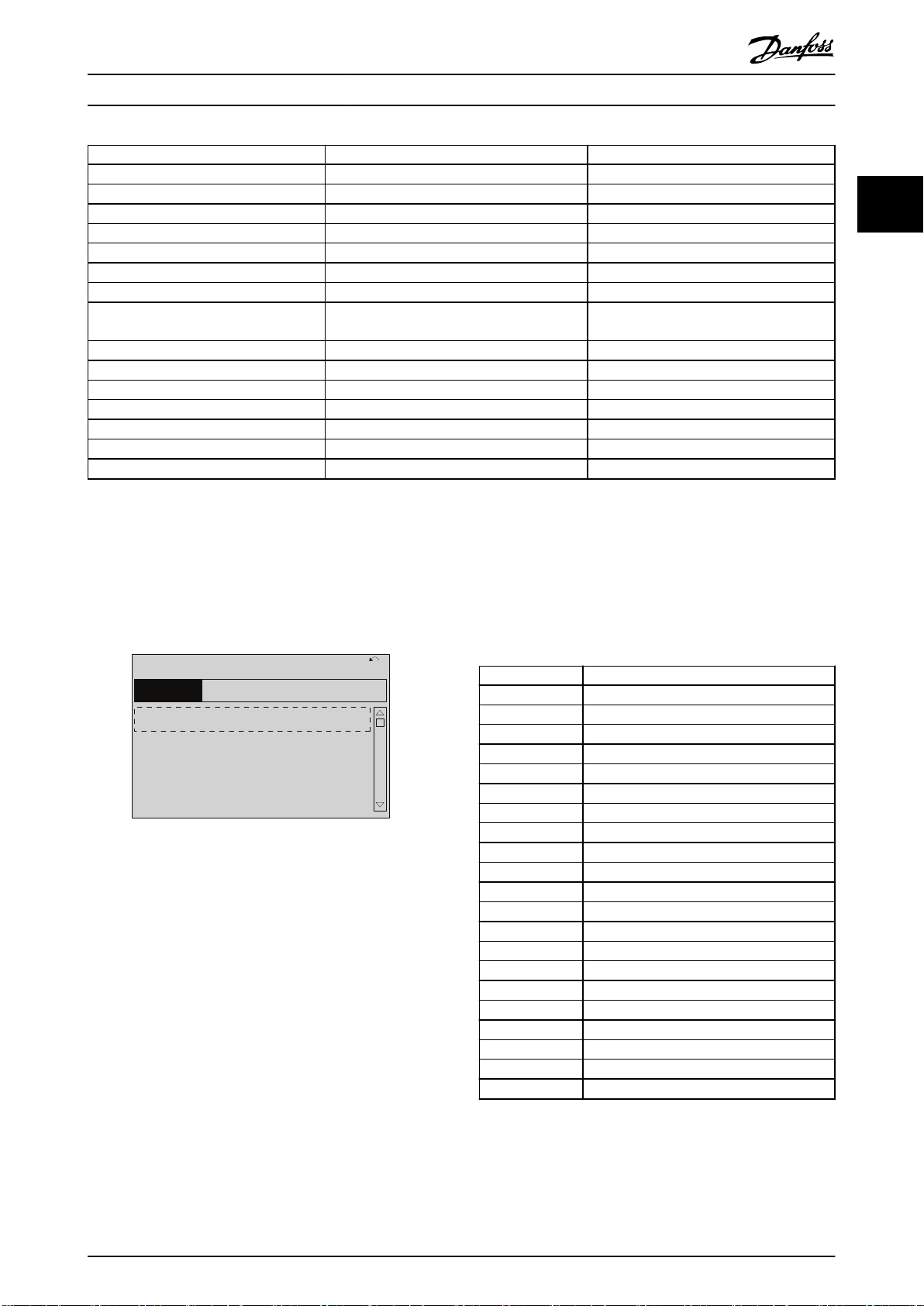
2.1.6 Main Menu Mode
To select the Main Menu mode, press the [Main Menu] key.
Lines 2–5 on the display show parameter groups which
can be selected by pressing [▲] and [▼].
Illustration 2.22 Display Example
Each parameter has a name and a number which remain
the same regardless of the programming mode. In the
Main Menu mode, the parameters are divided into groups.
All parameters can be changed in the Main Menu. The
conguration of the unit (parameter 1-00 Conguration
Mode) determines other parameters available for
programming. For example, selecting [3] Process Closed
Loop enables additional parameters related to closed-loop
operation. Options installed on the frequency converter
enable extra parameters associated with the option.
2.1.7 Parameter Selection
In the Main Menu mode, the parameters are divided into
groups. Press the navigation keys to select parameter
group.
The following parameter groups are accessible:
Group number Parameter group
0-** Operation/Display
1-** Load/Motor
2-** Brakes
3-** References/Ramps
4-** Limits/Warnings
5-** Digital In/Out
6-** Analog In/Out
8-** Comm. and Options
11-** LonWorks
13-** Smart Logic
14-** Special Functions
15-** Drive Information
16-** Data Readouts
18-** Info & Readouts
20-** Drive Closed Loop
21-** Ext. Closed Loop
22-** Application Functions
23-** Time-based Functions
25-** Pack Controller
26-** Analog I/O Option
28-** Compressor Functions
Table 2.6 Parameter Groups
MG16H202 Danfoss A/S © 05/2016 All rights reserved. 21
After selecting a parameter group, press the navigation
keys to select a parameter.
Page 24
130BP067.10
740RPM
0 -01 Language
[0] English
10.64A 1 [1]
0-0
*
Basic Settings
130BP068.10
740RPM
0 -01 Language
[0] English
10.64 A 1 [1]
0-0
*
Basic Settings
130BP069.10
1- 6*
113 RPM 1.78 A 1(1)
Load depen. setting
1 - 60 Low speed load
compensation
100%
130BP070.10
1 - 60 Low speed load
compensation
1 0%
Load depen. setting 1- 6*
729RPM 6.21A 1(1)
6
How to Program
VLT® Refrigeration Drive FC 103
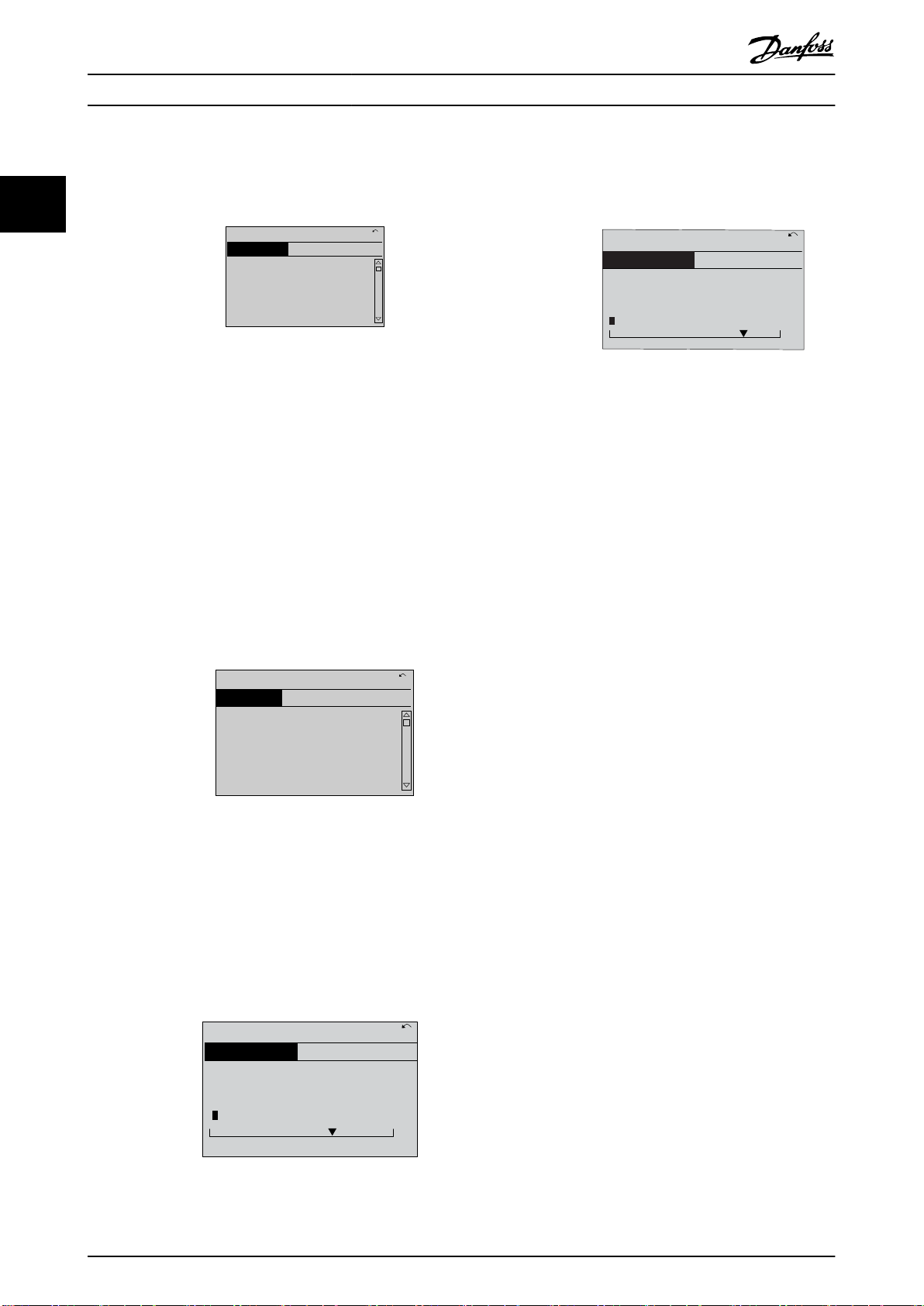
The middle section on the display shows the parameter
number and name, as well as the selected parameter
value.
Press the [▲] [▼] keys to change the data value. [▲]
increases the data value, and [▼] decreases the data value.
Place the cursor on the value to save and press [OK].
22
Illustration 2.23 Parameter Selection
Illustration 2.26 Changing a Group of Numeric Data Values
2.1.8 Changing Data
2.1.11 Value, Step-by-step
Press [OK] to change the selected parameter. The
procedure for changing data depends on whether the
selected parameter represents a numerical data value or a
text value.
2.1.9 Changing a Text Value
If the selected parameter is a text value, change the text
value with the [▲] [▼] keys.
Place the cursor on the value that should be saved and
press [OK].
Certain parameters can be changed step by step. This
applies to:
Parameter 1-20 Motor Power [kW].
•
Parameter 1-22 Motor Voltage.
•
Parameter 1-23 Motor Frequency.
•
The parameters are changed both as a group of numeric
data values and as numeric data values that are
innitely
varying.
2.1.12 Read out and Programming of
Indexed Parameters
Parameters are indexed when placed in a rolling stack.
Parameter 15-30 Alarm Log: Error Code to
parameter 15-33 Alarm Log: Date and Time contain a fault
log which can be read out. Select a parameter, press [OK],
and use the [▲]/[▼] navigation keys to scroll through the
Illustration 2.24 Changing a Text Value
value log.
Use parameter 3-10 Preset Reference as another example:
2.1.10 Changing a Group of Numeric Data
Values
Select the parameter, press [OK], and use the [▲]/[▼]
navigation keys to scroll through the indexed values. To
change the parameter value, select the indexed value and
If the selected parameter represents a numeric data value,
change the data value pressing the [◀] [▶] navigation keys,
as well as the [▲] [▼] navigation keys. Press [◀] [▶] keys to
press [OK]. To change the value, press the [▲]/[▼] keys.
Press [OK] to accept the new setting. Press [Cancel] to
abort. Press [Back] to leave the parameter.
move the cursor horizontally.
2.1.13 Initialization to Default Settings
Initialize the frequency converter to default settings in 2
ways.
Recommended initialization (via
parameter 14-22 Operation Mode)
1. Select parameter 14-22 Operation Mode.
Illustration 2.25 Changing a Group of Numeric Data Values
22 Danfoss A/S © 05/2016 All rights reserved. MG16H202
2. Press [OK].
3. Select [2] Initialization.
Page 25

How to Program Programming Guide
4. Press [OK].
5. Cut o the mains supply and wait until the
display turns o.
6. Reconnect the mains supply - the frequency
converter is now reset.
7. Change parameter 14-22 Operation Mode back to
[0] Normal Operation.
NOTICE
Resets parameters selected in Personal Menu with
default factory setting.
Parameter 14-22 Operation Mode initializes all
except:
Parameter 14-50 RFI Filter.
Parameter 8-30 Protocol.
Parameter 8-31 Address.
Parameter 8-32 Baud Rate.
Parameter 8-35 Minimum Response Delay.
Parameter 8-36 Maximum Response Delay.
Parameter 8-37 Maximum Inter-Char Delay.
Parameter 15-00 Operating hours to
parameter 15-05 Over Volt's.
Parameter 15-20 Historic Log: Event to
parameter 15-22 Historic Log: Time.
Parameter 15-30 Alarm Log: Error Code to
parameter 15-32 Alarm Log: Time.
Manual initialization
1. Disconnect from mains and wait until the display
turns o.
2. 2a Press [Status] - [Main Menu] - [OK] at
the same time while powering up (LCP
102, graphical display).
2b Press [Menu] while powering up (LCP
101, numerical display).
3. Release the keys after 5 s.
4. The frequency converter is now programmed
according to default settings.
This procedure initializes all except:
Parameter 15-00 Operating hours.
•
Parameter 15-03 Power Up's.
•
Parameter 15-04 Over Temp's.
•
Parameter 15-05 Over Volt's.
•
NOTICE
Manual initialization:
Resets serial communication.
•
Resets parameter 14-50 RFI Filter and fault log
•
settings.
Removes parameters selected in
•
parameter 25-00 Pack Controller.
NOTICE
After initialization and power cycling, the display does
not show any information until after a couple of minutes.
2 2
MG16H202 Danfoss A/S © 05/2016 All rights reserved. 23
Page 26
Parameter Description
3 Parameter Description
VLT® Refrigeration Drive FC 103
3.1 Parameter Selection
33
3.1.1 Main Menu Structure
Parameters for the frequency converter are grouped into
various parameter groups for easy selection of the correct
parameters for optimized operation of the frequency
converter.
Most refrigeration applications can be programmed by
pressing [Quick Menu] and selecting the parameters under
Quick Setup and Function Set-ups.
Descriptions and default settings of parameters are in
chapter 4 Parameter Lists.
Parameter groups
0-** Operation/Display
•
1-** Load and Motor
•
2-** Brakes
•
3-** Reference/Ramps
•
4-** Limits/Warnings
•
5-** Digital In/Out
•
6-** Analog In/Out
•
8-** Comm. and Options
•
11-** LonWorks
•
13-** Smart Logic
•
14-** Special Functions
•
15-** Drive Information
•
16-** Data Readouts
•
18-** Info & Readouts
•
20-** Drive Closed Loop
•
21-** Ext. Closed Loop
•
22-** Appl. Functions
•
23-** Time-based Functions
•
25-** Pack Controller
•
26-** Analog I/O Option
•
28-** Compressor Functions
•
Parameters: 0-** Operation and Display
3.2
Parameters related to the fundamental functions of the
frequency converter, function of the LCP keys, and congu-
ration of the LCP display.
0-01 Language
Option: Function:
Denes the language to be used in the
display.
The frequency converter is delivered with
2 dierent language packages. English and
German are included in both packages.
English cannot be erased or manipulated.
[0] * English Part of language packages 1–2.
[1] Deutsch Part of language packages 1–2.
[2] Francais Part of language package 1.
[3] Dansk Part of language package 1.
[4] Spanish Part of language package 1.
[5] Italiano Part of language package 1.
[6] Svenska Part of language package 1.
[7] Nederlands Part of language package 1.
[10] Chinese Part of language package 2.
[20] Suomi Part of language package 1.
[22] English US Part of language package 1.
[27] Greek Part of language package 1.
[28] Bras.port Part of language package 1.
[36] Slovenian Part of language package 1.
[39] Korean Part of language package 2.
[40] Japanese Part of language package 2.
[41] Turkish Part of language package 1.
[42] Trad.Chinese Part of language package 2.
[43] Bulgarian Part of language package 1.
[44] Srpski Part of language package 1.
[45] Romanian Part of language package 1.
[46] Magyar Part of language package 1.
[47] Czech Part of language package 1.
[48] Polski Part of language package 1.
[49] Russian Part of language package 1.
[50] Thai Part of language package 2.
[51] Bahasa
Indonesia
[52] Hrvatski Part of language package 2.
Part of language package 2.
24 Danfoss A/S © 05/2016 All rights reserved. MG16H202
Page 27
Parameter Description Programming Guide
0-02 Motor Speed Unit
Option: Function:
NOTICE
This parameter cannot be adjusted while the
motor is running.
The information shown in the display depends on
settings in parameter 0-02 Motor Speed Unit and
parameter 0-03 Regional Settings. The default settings
of parameter 0-02 Motor Speed Unit and
parameter 0-03 Regional Settings depend on to which
region of the world the frequency converter is
supplied.
NOTICE
Changing the motor speed unit resets certain
parameters to their initial value. Select the
motor speed unit before modifying other
parameters.
[0] RPM Select to show motor speed variables and parameters
using motor speed (RPM).
[1] * Hz Select to show motor speed variables and parameters
using output frequency (Hz).
0-03 Regional Settings
Option: Function:
NOTICE
This parameter cannot be adjusted while
the motor is running.
The display output depends on the settings in
parameter 0-02 Motor Speed Unit and
parameter 0-03 Regional Settings. The default
settings of parameter 0-02 Motor Speed Unit and
parameter 0-03 Regional Settings depend on which
region of the world the frequency converter is
supplied to. Reprogram the settings as required.
The settings not used are made invisible.
[0] Interna-
tional
[1] North
America
0-04 Operating State at Power-up
Option: Function:
Sets parameter 1-20 Motor Power [kW] units to
[kW] and the default value of
parameter 1-23 Motor Frequency [50 Hz].
Sets parameter 1-21 Motor Power [HP] units to [hp]
and the default value of parameter 1-23 Motor
Frequency to 60 Hz.
Select the operating mode after reconnection of
the frequency converter to mains voltage after
power-down when operating in hand-on (local)
mode.
0-04 Operating State at Power-up
Option: Function:
[0] * Resume Resumes operation of the frequency converter
maintaining the same local reference and the
same start/stop condition (applied by [Hand
On]/[O] on the LCP or local start via a digital
input as before the frequency converter was
powered down.
[1] Forced
stop,
ref=old
Stops the frequency converter, but at the same
time retains the local speed reference before
power-down in the memory. After mains
voltage is reconnected and after receiving a
start command (pressing [Hand On] or local
start command via a digital input), the
frequency converter restarts and operates at the
retained speed reference.
0-05 Local Mode Unit
Option: Function:
Denes if the local reference unit is shown
in terms of the motor shaft speed (in
RPM/Hz) or as percent.
[0] * As Motor
Speed Unit
[1] %
3.2.1 0-1* Set-up Operations
Dene and control the individual parameter set-ups.
The frequency converter has 4 parameter set-ups that can
be programmed independently of each other. This makes
the frequency converter very exible and able to meet the
requirements of many dierent refrigeration system control
schemes, often saving the cost of external control
equipment. For example, these can be used to program
the frequency converter to operate according to 1 control
scheme in 1 set-up (for example daytime operation) and
another control scheme in another set-up (for example
night setback). Alternatively, they can be used by an AHU
or packaged unit OEM to identically program all their
factory tted frequency converters for dierent equipment
models within a range to have the same parameters, and
then during production/commissioning simply select a
specic set-up depending on which model within that
range the frequency converter is installed on.
The active set-up (that is the set-up in which the frequency
converter is currently operating) can be selected in
parameter 0-10 Active Set-up and is shown in the LCP. Use
[9] Multi set-up to switch between set-ups with the
frequency converter running or stopped, via digital input
or serial communication commands (for example for night
setback). If it is necessary to change setups while running,
ensure that parameter 0-12 This Set-up Linked to is
programmed as required. For most refrigeration
applications it is not necessary to program
parameter 0-12 This Set-up Linked to even if change of set-
3 3
MG16H202 Danfoss A/S © 05/2016 All rights reserved. 25
Page 28
Parameter Description
VLT® Refrigeration Drive FC 103
up while running is required. However, for complex
applications, using the full exibility of the multiple setups, programming parameter 0-12 This Set-up Linked to may
be required. Using parameter 0-11 Programming Set-up, it is
possible to edit parameters within any of the set-ups while
continuing the frequency converter operation in its active
33
set-up which can be a dierent set-up to the one being
edited. Using parameter 0-51 Set-up Copy, it is possible to
copy parameter settings between the set-ups to enable
quicker commissioning if similar parameter settings are
required in dierent set-ups.
0-10 Active Set-up
Option: Function:
Select the set-up in which the frequency
converter is to operate.
Use parameter 0-51 Set-up Copy to copy a set-up
to 1 or all other set-ups. To avoid conicting
settings of the same parameter within 2
dierent set-ups, link the set-ups using
parameter 0-12 This Set-up Linked to. Stop the
frequency converter before switching between
set-ups where parameters marked not
changeable during operation have dierent
values.
Parameters which are not changeable during
operation are marked FALSE in
chapter 4 Parameter Lists.
[0] Factory
setup
[1]*Set-up 1 [1] Set-up 1 to [4] Set-up 4 are the 4 parameter
[2] Set-up 2
[3] Set-up 3
[4] Set-up 4
[9] Multi Set-upIs used for remote set-up selections using digital
Cannot be changed. It contains the Danfoss
data set, and can be used as a data source
when returning the other set-ups to a known
state.
set-ups within which all parameters can be
programmed.
inputs and the serial communication port. This
set-up uses the settings from
parameter 0-12 This Set-up Linked to.
0-11 Programming Set-up
Option: Function:
Select the set-up to be edited (that is
programmed) during operation; either the
active set-up or 1 of the inactive set-ups. The
set-up number being edited is shown in the
LCP in brackets.
[0] Factory
setup
Cannot be edited, but it is useful as a data
source to return the other set-ups to a known
state.
0-11 Programming Set-up
Option: Function:
[1] Set-up 1 [1] Set-up 1 to [4] Set-up 4 can be edited freely
during operation, independently of the active
set-up.
[2] Set-up 2
[3] Set-up 3
[4] Set-up 4
[9] * Active Set-upThe set-up in which the frequency converter is
operating can be edited during operation.
Editing parameters in the selected set-up
would normally be done from the LCP, but it is
also possible from any of the serial communication ports.
0-12 This Set-up Linked to
Option: Function:
Use this parameter only if a change of set-ups
is required while the motor is running. This
parameter ensures that parameters which are
not changeable during operation have the
same setting in all relevant set-ups.
To enable conict-free changes from 1 set-up to
another while the frequency converter is
running, link set-ups containing parameters
which are not changeable during operation.
The link ensures synchronizing of the not
changeable during operation parameter values
when moving from 1 set-up to another during
operation. Not changeable during operation
parameters can be identied by the label FALSE
in the parameter lists in chapter 4 Parameter
Lists.
The parameter 0-12 This Set-up Linked to feature
is used when [9] Multi set-up in
parameter 0-10 Active Set-up is selected. Use [9]
Multi set-up to move from 1 set-up to another
during operation while the motor runs.
For example:
Use [9] Multi set-up to shift from set-up 1 to setup 2 while the motor runs. Program parameters
in set-up 1 rst, then ensure that set-up 1 and
set-up 2 are synchronized (or linked).
Synchronization can be performed in 2 ways:
Change the edit set-up to [2] Set-up 2
•
in parameter 0-11 Programming Set-up
and set parameter 0-12 This Set-up
Linked to to [1] Set-up 1. This starts the
linking (synchronizing) process.
26 Danfoss A/S © 05/2016 All rights reserved. MG16H202
Page 29
130BP075.10
0-12 This Set-up Linked to
0 RPM
0.00A
1(1)
Set-up Handling 0-1*
[1]
Setup 1
130BP076.10
0-12 This Set-up Linked to
0 RPM
0.00A
1(1)
Set-up Handling
0-1*
[2]
Setup 2
Parameter Description Programming Guide
0-12 This Set-up Linked to
Option: Function:
Illustration 3.1 Set-up Handling
While still in set-up 1, using
•
parameter 0-50 LCP Copy, copy set-up
1 to set-up 2. Then set
parameter 0-12 This Set-up Linked to to
[2] Set-up 2. This starts the linking
process.
Illustration 3.2 Set-up Handling
After the link is complete,
parameter 0-13 Readout: Linked Set-ups reads
set-ups 1 and 2 to indicate that all not
changeable during operation parameters are now
the same in set-up 1 and set-up 2. If there are
changes to a not changeable during operation
parameter in set-up 2, for example
parameter 1-30 Stator Resistance (Rs), they are
also changed automatically in set-up 1. A
switch between set-up 1 and set-up 2 during
operation is now possible.
[0] * Not linked
[1] Set-up 1
[2] Set-up 2
[3] Set-up 3
[4] Set-up 4
0-13 Readout: Linked Set-ups
Array [5]
Range: Function:
0* [0 -
255]
View a list of all the set-ups linked by
parameter 0-12 This Set-up Linked to. The parameter
has 1 index for each parameter set-up. The value
for each index shows which set-ups are linked to
that parameter set-up.
0-13 Readout: Linked Set-ups
Array [5]
Range: Function:
Index LCP value
0 {0}
1 {1,2}
2 {1,2}
3 {3}
4 {4}
Table 3.1 Set-up Link Example
0-14 Readout: Prog. Set-ups / Channel
Range: Function:
0* [-2147483648
- 2147483647]
View the setting of
parameter 0-11 Programming Set-up for each
of the 4 dierent communication channels.
When the number is shown in hex, as it is in
the LCP, each number shows 1 channel.
Numbers 1–4 show a set-up number; F
stands for the factory setting, and A stands
for an active set-up. The channels are, from
right to left: LCP, eldbus, USB, HPFB1.5.
Example: The value AAAAAA21h means that
the eldbus channel uses set-up 2 in
parameter 0-11 Programming Set-up, the LCP
uses set-up 1, and all other channels use the
active set-up.
3.2.2 0-2* LCP Display
Dene the variables shown in the LCP.
NOTICE
For information on how to write display texts, refer to:
Parameter 0-37 Display Text 1.
•
Parameter 0-38 Display Text 2.
•
Parameter 0-39 Display Text 3.
•
0-20 Display Line 1.1 Small
Option: Function:
Select a variable for display in line 1,
left position.
[37] Display Text 1 Enables an individual text string to be
written for display in the LCP, or to be
read via serial communication.
[38] Display Text 2 Enables an individual text string to be
written for display in the LCP, or to be
read via serial communication.
3 3
MG16H202 Danfoss A/S © 05/2016 All rights reserved. 27
Page 30
Parameter Description
VLT® Refrigeration Drive FC 103
0-20 Display Line 1.1 Small
Option: Function:
[39] Display Text 3 Enables an individual text string to be
written for display in the LCP, or to be
read via serial communication.
33
[89] Date and Time
Readout
[953] Probus
Warning Word
[1397] Alert Alarm
Word
[1398] Alert Warning
Word
[1399] Alert Status
Word
[1501] Running Hours View the number of running hours of
[1502] kWh Counter View the mains power consumption in
[1580] Fan Running
Hours
[1600] Control Word View the control word sent from the
[1601] Reference [Unit] Total reference (sum of digital/analog/
[1602] Reference [%] Total reference (sum of digital/analog/
[1603] Status Word Present status word
[1605] Main Actual
Value [%]
[1609] Custom Readout View the user-dened readouts as
[1610] Power [kW ] Actual power consumed by the motor
[1611] Power [hp] Actual power consumed by the motor
[1612] Motor Voltage Voltage supplied to the motor.
[1613] Frequency Motor frequency, that is the output
Displays the current date and time.
Displays PROFIBUS communication
warnings.
the motor.
kWh.
frequency converter via the serial
communication port in hex code.
preset/bus/freeze reference/catch up,
and slow-down) in selected unit.
preset/bus/freeze reference/catch up,
and slow-down) in percent.
View the 2-byte word sent with the
status word to the bus master
reporting the main actual value.
dened in:
Parameter 0-30 Custom
•
Readout Unit.
Parameter 0-31 Custom
•
Readout Min Value.
Parameter 0-32 Custom
•
Readout Max Value.
in kW.
in hp.
frequency from the frequency converter
in Hz.
0-20 Display Line 1.1 Small
Option: Function:
[1614] Motor current Phase current of the motor measured
as eective value.
[1615] Frequency [%] Motor frequency, that is the output
frequency from the frequency converter
in percent.
[1616] Torque [Nm] Present motor load as a percentage of
the rated motor torque.
[1617] Speed [RPM] Motor speed reference. Actual speed
depends on slip compensation being
used (compensation set in
parameter 1-62 Slip Compensation). If
not used, actual speed is the value
read in the display minus motor slip.
[1618] Motor Thermal Thermal load on the motor, calculated
by the ETR function. See also parameter
group 1-9* Motor Temperature.
[1622] Torque [%] Shows the actual torque produced, in
percentage.
[1624] Calibrated Stator
Resistance
[1630] DC Link Voltage Intermediate circuit voltage in the
frequency converter.
[1631] System Temp.
[1632] Brake Energy /s Present brake power transferred to an
external brake resistor.
Stated as an instant value.
[1633] Brake Energy /2
min
[1634] Heatsink Temp. Present heat sink temperature of the
[1635] Inverter Thermal Percentage load of the inverters.
[1636] Inv. Nom.
Current
[1637] Inv. Max.
Current
[1638] SL Controller
State
[1639] Control Card
Temp.
[1650] External
Reference
[1652] Feedback[Unit] Reference value from programmed
Brake power transferred to an external
brake resistor. The average power is
calculated continuously for the most
recent 120 s.
frequency converter. The cutout limit is
95 ±5 °C (203 ±9 °F); cutting back in
occurs at 70 ± 5 °C (158 ±9 °F).
Nominal current of the frequency
converter.
Maximum current of the frequency
converter.
State of the event executed by the
control.
Temperature of the control card.
Sum of the external reference as a
percentage, that is the sum of analog/
pulse/bus.
digital input(s).
28 Danfoss A/S © 05/2016 All rights reserved. MG16H202
Page 31
Parameter Description Programming Guide
0-20 Display Line 1.1 Small
Option: Function:
[1653] Digi Pot
Reference
[1654] Feedback 1
[Unit]
[1655] Feedback 2
[Unit]
[1656] Feedback 3
[Unit]
[1660] Digital Input Shows the status of the digital inputs.
[1661] Terminal 53
Switch Setting
[1662] Analog Input 53 Actual value at input 53 either as a
[1663] Terminal 54
Switch Setting
[1664] Analog Input 54 Actual value at input 54 either as
[1665] Analog Output
42 [mA]
[1666] Digital Output
[bin]
[1667] Pulse Input #29
[Hz]
[1668] Pulse Input #33
[Hz]
[1669] Pulse Output
#27 [Hz]
[1670] Pulse Output
#29 [Hz]
[1671] Relay Output
[bin]
[1672] Counter A View the present value of counter A.
[1673] Counter B View the present value of counter B.
[1675] Analog In
X30/11
[1676] Analog In
X30/12
[1677] Analog Out
X30/8 [mA]
View the contribution of the digital
potentiometer to the actual reference
feedback.
View the value of feedback 1. See also
parameter group 20-0* FC Closed Loop.
View the value of feedback 2. See also
parameter group 20-0* FC Closed Loop.
View the value of feedback 3. See also
parameter group 20-0* FC Closed Loop.
Signal low = 0; Signal high = 1.
Regarding order, see
parameter 16-60 Digital Input. Bit 0 is at
the extreme right.
Setting of input terminal 53. Current =
0; Voltage = 1.
reference or protection value.
Setting of input terminal 54. Current =
0; Voltage = 1.
reference or protection value.
Actual value at output 42 in mA. Use
parameter 6-50 Terminal 42 Output to
select the variable to be represented by
output 42.
Binary value of all digital outputs.
Actual value of the frequency applied
at terminal 29 as a pulse input.
Actual value of the frequency applied
at terminal 33 as a pulse input.
Actual value of pulses applied to
terminal 27 in digital output mode.
Actual value of pulses applied to
terminal 29 in digital output mode.
View the setting of all relays.
Actual value of the signal on input
X30/11 (general purpose I/O card.
Optional).
Actual value of the signal on input
X30/12 (general purpose I/O card.
Optional).
Actual value at output X30/8 (general
purpose I/O card. Optional). Use
0-20 Display Line 1.1 Small
Option: Function:
parameter 6-60 Terminal X30/8 Output to
select the variable to be shown.
[1678] Analog Out
X45/1 [mA]
[1679] Analog Out
X45/3 [mA]
[1680] Fieldbus CTW 1 Control word (CTW) received from the
bus master.
[1682] Fieldbus REF 1 Main reference value sent with control
word via the serial communications
network, for example from the BMS,
PLC, or other master controller.
[1684] Comm. Option
STW
[1685] FC Port CTW 1 Control word (CTW) received from the
[1686] FC Port REF 1 Status word (STW) sent to the bus
[1690] Alarm Word One or more alarms in a hex code
[1691] Alarm Word 2 One or more alarms in a hex code
[1692] Warning Word One or more warnings in a hex code
[1693] Warning Word 2 One or more warnings in a hex code
[1694] Ext. Status Word One or more status conditions in a hex
[1695] Ext. Status Word2One or more status conditions in a hex
[1696] Maintenance
Word
[1699] Ext. Status Word
3
[1830] Analog Input
X42/1
[1831] Analog Input
X42/3
[1832] Analog Input
X42/5
[1833] Analog Out
X42/7 [V]
Extended eldbus communication
option status word.
bus master.
master.
(used for serial communications).
(used for serial communications).
(used for serial communications).
(used for serial communications).
code (used for serial communications).
code (used for serial communications).
The bits reect the status for the
programmed preventive maintenance
events in parameter group 23-1*
Maintenance.
Shows the value of the signal applied
to terminal X42/1 on the analog I/O
card.
Shows the value of the signal applied
to terminal X42/3 on the analog I/O
card.
Shows the value of the signal applied
to terminal X42/5 on the analog I/O
card.
Shows the value of the signal applied
to terminal X42/7 on the analog I/O
card.
3 3
MG16H202 Danfoss A/S © 05/2016 All rights reserved. 29
Page 32

Parameter Description
VLT® Refrigeration Drive FC 103
0-20 Display Line 1.1 Small
Option: Function:
[1834] Analog Out
X42/9 [V]
33
[1835] Analog Out
X42/11 [V]
[1857] Air Pressure to
Flow Air Flow
[1860] Digital Input 2
[1870] Mains Voltage
[1871] Mains
Frequency
[1872] Mains Imbalance
[1875] Rectier DC Volt.
[2117] Ext. 1 Reference
[Unit]
[2118] Ext. 1 Feedback
[Unit]
[2119] Ext. 1 Output
[%]
[2137] Ext. 2 Reference
[Unit]
[2138] Ext. 2 Feedback
[Unit]
[2139] Ext. 2 Output
[%]
[2157] Ext. 3 Reference
[Unit]
[2158] Ext. 3 Feedback
[Unit]
[2159] Ext. 3 Output
[%]
[2230] No-Flow Power The calculated no-ow power for the
[2316] Maintenance
Text
[2580] Pack Status Status for the operation of the pack
[2581] Compressor
Status
[2587] Inverse Interlock
[2588] Pack capacity
[%]
[2827] Discharge
Temperature
[3038] Pressure 1
[3048] Pressure 2
[9920] Fan Ctrl deltaT
Shows the value of the signal applied
to terminal X42/9 on the analog I/O
card.
Shows the value of the signal applied
to terminal X42/11 on the analog I/O
card.
The value of the reference for extended
closed-loop controller 1.
The value of the feedback signal for
extended closed-loop controller 1.
The value of the output from extended
closed-loop controller 1.
The value of the reference for extended
closed-loop controller 2.
The value of the feedback signal for
extended closed-loop controller 2.
The value of the output from extended
closed-loop controller 2.
The value of the reference for extended
closed-loop controller 3.
The value of the feedback signal for
extended closed-loop controller 3.
The value of the output from extended
closed-loop controller 3.
actual operating speed.
controller.
Status for the operation of each
individual compressor controlled by the
pack controller.
0-20 Display Line 1.1 Small
Option: Function:
[9921] Fan Ctrl Tmean
[9922] Fan Ctrl NTC
Cmd
[9923] Fan Ctrl i-term
[9924] Rectier Current
[9952] PC Debug 0
[9953] PC Debug 1
[9954] PC Debug 2
[9961] FPC Debug 0
[9962] FPC Debug 1
[9963] FPC Debug 2
[9964] FPC Debug 3
[9965] FPC Debug 4
0-21 Display Line 1.2 Small
Option: Function:
Application
dependent
Select a variable for display in line 1, middle
position. The options are the same as listed
for parameter 0-20 Display Line 1.1 Small.
0-22 Display Line 1.3 Small
Option: Function:
Application
dependent
Select a variable for display in line 1, right
position.
The options are the same as listed for
parameter 0-20 Display Line 1.1 Small.
0-23 Display Line 2 Large
Option: Function:
Application
dependent
Select a variable for display in line 2.
The options are the same as listed for
parameter 0-20 Display Line 1.1 Small.
0-24 Display Line 3 Large
Option: Function:
Application
dependent
Select a variable for display in line 3.
The options are the same as listed for
parameter 0-20 Display Line 1.1 Small.
30 Danfoss A/S © 05/2016 All rights reserved. MG16H202
Page 33

Custom Readout (Value)
P 16-09
Custom Readout
Unit P 0-30
Max value
P 0-32
Min value
P 0-31
Linear
units only
Quadratic Unit (Pressure)
Cubic Unit (Power)
Motor Speed
Motor Speed
High limit
P 4-13 (RPM)
P 4-14 (Hz)
0
130BT105.12
Linear Unit (e.g. speed and ow)
Parameter Description Programming Guide
0-25 My Personal Menu
Array [20]
Range: Function:
Size
related*
3.2.3 0-3* LCP Custom Readout
It is possible to customize the display elements for various
purposes:
Custom readout
The calculated value to be shown is based on the settings
in:
Illustration 3.3 Custom Readout
MG16H202 Danfoss A/S © 05/2016 All rights reserved. 31
[0 9999]
Custom readout. Value proportional to speed
•
Dene up to 20 parameters to appear in the
Q1 Personal Menu, accessible via the [Quick
Menu] key on the LCP. The parameters are
displayed in the Q1 Personal Menu in the
order they are programmed into this array
parameter. Delete parameters by setting the
value to 0000.
For example, this can be used to provide
quick, simple access to just 1 or up to 20
parameters which require changing on a
regular basis (for example, for plant
maintenance reasons) or by an OEM to
enable simple commissioning of their
equipment.
(linear, squared, or cubed depending on unit
selected in parameter 0-30 Custom Readout Unit).
Display text. Text string stored in a parameter.
•
Parameter 0-30 Custom Readout Unit.
•
Parameter 0-31 Custom Readout Min Value (linear
•
only).
Parameter 0-32 Custom Readout Max Value.
•
Parameter 4-13 Motor Speed High Limit [RPM].
•
Parameter 4-14 Motor Speed High Limit [Hz].
•
Actual speed.
•
The relation depends on the type of unit selected in
parameter 0-30 Custom Readout Unit:
Unit type Speed relation
Dimensionless
Speed
Flow, volume
Flow, mass
Velocity
Length
Temperature
Pressure Quadratic
Power Cubic
Table 3.2 Speed Relations for Dierent Unit Types
Linear
0-30 Custom Readout Unit
Option: Function:
Program a value to be shown in the LCP display.
The value has a linear, squared, or cubed relation
to speed. This relation depends on the unit
selected (see Table 3.2). The actual calculated
value can be read in parameter 16-09 Custom
Readout, and/or shown in the display by selecting
[1609] Custom Readout in parameter 0-20 Display
Line 1.1 Small to parameter 0-24 Display Line 3
Large.
[0]
[1] * %
[5] PPM
[10] 1/min
[11] RPM
[12] Pulse/s
[20] l/s
[21] l/min
[22] l/h
[23] m³/s
[24] m³/min
[25] m³/h
[30] kg/s
[31] kg/min
[32] kg/h
[33] t/min
[34] t/h
[40] m/s
[41] m/min
[45] m
[60] °C
[70] mbar
[71] bar
[72] Pa
[73] kPa
[74] m WG
[80] kW
[120] GPM
3 3
Page 34

Parameter Description
VLT® Refrigeration Drive FC 103
0-30 Custom Readout Unit
Option: Function:
[121] gal/s
[122] gal/min
[123] gal/h
33
[124] CFM
[125] ft³/s
[126] ft³/min
[127] ft³/h
[130] lb/s
[131] lb/min
[132] lb/h
[140] ft/s
[141] ft/min
[145] ft
[160] °F
[170] psi
[171] lb/in²
[172] in WG
[173] ft WG
[180] HP
0-31 Custom Readout Min Value
Range: Function:
Size
related*
[ 0 - 0
CustomReadoutUnit]
This parameter allows selection of
the minimum value of the custom-
dened readout (occurs at zero
speed). It is only possible to select a
value dierent from 0 when selecting
a linear unit in
parameter 0-30 Custom Readout Unit.
For quadratic and cubic units the
minimum value is 0.
0-37 Display Text 1
Range: Function:
•
•
•
•
•
•
Changing parameter 12-08 Host Name changes
parameter 0-37 Display Text 1 - but not vice versa.
0-38 Display Text 2
Range: Function:
0* [0 -
In this parameter, it is possible to write an individual
25]
text string to show in the LCP or to be read via serial
communication.
To show the text permanently, select [38] Display Text
2 in:
•
•
•
•
•
Press [▲] or [▼] to change a character. Press [◀] and
[▶] to move the cursor. When a character is
highlighted by the cursor, this character can be
changed. A character can be inserted by placing the
cursor between 2 characters and pressing [▲] or [▼].
Parameter 0-20 Display Line 1.1 Small.
Parameter 0-21 Display Line 1.2 Small.
Parameter 0-22 Display Line 1.3 Small.
Parameter 0-23 Display Line 2 Large.
Parameter 0-24 Display Line 3 Large.
Parameter 0-37 Display Text 1.
Parameter 0-20 Display Line 1.1 Small.
Parameter 0-21 Display Line 1.2 Small.
Parameter 0-22 Display Line 1.3 Small.
Parameter 0-23 Display Line 2 Large.
Parameter 0-24 Display Line 3 Large.
0-39 Display Text 3
0-32 Custom Readout Max Value
Range: Function:
100 CustomReadoutUnit*
[ par. 0-31 -
999999.99
CustomReadoutUnit]
This parameter sets the
maximum value to be shown
when the speed of the motor
has reached the set value for
parameter 4-13 Motor Speed High
Limit [RPM] or
parameter 4-14 Motor Speed High
Limit [Hz] (depends on setting in
parameter 0-02 Motor Speed
Unit).
0-37 Display Text 1
Range: Function:
0* [0 -
In this parameter, it is possible to write an individual
25]
text string to show in the LCP or to be read via serial
communication. To show the text permanently, select
display text 3 in parameter 0-20 Display Line 1.1 Small,
parameter 0-21 Display Line 1.2 Small,
parameter 0-22 Display Line 1.3 Small,
parameter 0-23 Display Line 2 Large, or
parameter 0-24 Display Line 3 Large. Press [▲] or [▼]
to change a character. Press [◀] and [▶] to move the
cursor. When a character is highlighted by the cursor,
this character can be changed. A character can be
inserted by placing the cursor between 2 characters
and pressing [▲] or [▼].
Range: Function:
0* [0 -
In this parameter, it is possible to write an individual
25]
text string to be shown in the LCP or to be read via
serial communication.
To show the text permanently, select [37] Display Text
1 in 1 of the following parameters:
32 Danfoss A/S © 05/2016 All rights reserved. MG16H202
Page 35

Parameter Description Programming Guide
3.2.4 0-4* LCP Keypad
Enable, disable, and password protect individual keys on
the LCP.
0-40 [Hand on] Key on LCP
Option: Function:
[0] Disabled Select to disable the key.
[1] * Enabled [Hand On] key enabled.
[2] Password Avoid unauthorized start in hand-on mode.
If parameter 0-40 [Hand on] Key on LCP is
included in My Personal Menu, dene the
password in parameter 0-65 Personal Menu
Password. Otherwise, dene the password in
parameter 0-60 Main Menu Password.
[9] Enabled, ref
= 0
0-41 [O] Key on LCP
Option: Function:
[0] Disabled Select to disable the key.
[1] * Enabled [O] key is enabled.
[2] Password Avoid unauthorized stop. If parameter 0-41 [O]
Key on LCP is included in My Personal Menu,
dene the password in parameter 0-65 Personal
Menu Password. Otherwise, dene the password
in parameter 0-60 Main Menu Password.
3.2.5 0-5* Copy/Save
Copy parameters from and to the LCP. Use these
parameters for saving and copying set-ups from 1
frequency converter to another.
0-50 LCP Copy
Option: Function:
NOTICE
This parameter cannot be adjusted
while the motor is running.
[0] * No copy
[1] All to LCP Copies all parameters in all set-ups from the
frequency converter memory to the LCP
memory. For service purposes, copy all
parameters to the LCP after commissioning.
[2] All from LCP Copies all parameters in all set-ups from the
LCP memory to the frequency converter
memory.
[3] Size indep.
from LCP
[10] Delete LCP
copy data
Copies only the parameters that are
independent of the motor size. Use the latest
selection to program several frequency
converters with the same function without
disturbing motor data which are already set.
3 3
0-42 [Auto on] Key on LCP
Option: Function:
[0] Disabled Select to disable the key.
[1] * Enabled [Auto On] key is enabled.
[2] Password Avoid unauthorized start in auto-on mode. If
parameter 0-42 [Auto on] Key on LCP is included
in My Personal Menu, dene the password in
parameter 0-65 Personal Menu Password.
Otherwise, dene the password in
parameter 0-60 Main Menu Password.
0-43 [Reset] Key on LCP
Option: Function:
[0] Disabled Select to disable the key.
[1] * Enabled [Reset] key is enabled.
[2] Password Avoid unauthorized resetting. If
parameter 0-43 [Reset] Key on LCP is included in
parameter 0-25 My Personal Menu, dene the
password in parameter 0-65 Personal Menu
Password. Otherwise, dene the password in
parameter 0-60 Main Menu Password.
0-51 Set-up Copy
Option: Function:
[0]*No copy No function.
[1] Copy to
set-up 1
[2] Copy to
set-up 2
[3] Copy to
set-up 3
[4] Copy to
set-up 4
[9] Copy to
all
Copies all parameters in the present
programming set-up (dened in
parameter 0-11 Programming Set-up) to set-up 1.
Copies all parameters in the present
programming set-up (dened in
parameter 0-11 Programming Set-up) to set-up 2.
Copies all parameters in the present
programming set-up (dened in
parameter 0-11 Programming Set-up) to set-up 3.
Copies all parameters in the present
programming set-up (dened in
parameter 0-11 Programming Set-up) to set-up 4.
Copies the parameters in the present set-up to
each of the set-ups 1 to 4.
MG16H202 Danfoss A/S © 05/2016 All rights reserved. 33
Page 36

Parameter Description
VLT® Refrigeration Drive FC 103
3.2.6 0-6* Password
0-67 Bus Password Access
Range: Function:
0-60 Main Menu Password
Range: Function:
100* [-9999 -
33
9999]
Dene the password for access to the Main
Menu via the [Main Menu] key. If
parameter 0-61 Access to Main Menu w/o
Password is set to [0] Full access, this parameter
is ignored.
0-61 Access to Main Menu w/o Password
Option: Function:
[0] * Full access Disables the password dened in
parameter 0-60 Main Menu Password. If this
option is selected, parameter 0-60 Main
Menu Password, parameter 0-65 Personal
Menu Password, and parameter 0-66 Access
to Personal Menu w/o Password are ignored.
[1] LCP: Read only Prevents unauthorized editing of Main
Menu parameters.
[2] LCP: No access Prevents unauthorized viewing and editing
of Main Menu parameters.
[3] Bus: Read only
[4] Bus: No access
[5] All: Read only
[6] All: No access
0-65 Personal Menu Password
Range: Function:
200* [-9999 -
9999]
Dene the password for access to My Personal
Menu via the [Quick Menu] key. If
parameter 0-66 Access to Personal Menu w/o
Password is set to [0] Full access, this parameter
is ignored.
0* [0 - 9999] Use this parameter to unlock the frequency
converter via eldbus or MCT 10 Set-up Software.
3.2.7 0-7* Clock Settings
Set the time and date of the internal clock. The internal
clock can be used for timed actions, energy log, trend
analysis, date/time stamps on alarms, logged data,
preventive maintenance, and so on.
It is possible to program the clock for daylight saving time/
summertime, weekly working days/non-working days
including 20 exceptions (holidays, and so on). Although the
clock settings can be set via the LCP, they can also be set
along with timed actions and preventative maintenance
functions using the MCT 10 Set-up Software tool.
NOTICE
The frequency converter has no back-up of the clock
function and the set date/time resets to default
(2000-01-01 00:00) after a power-down unless a real-time
clock-module with back-up is installed. If no module with
back-up is installed, only use the clock function if the
frequency converter is integrated into the BMS using
serial communications, with the BMS maintaining
synchronization of control equipment clock times. In
parameter 0-79 Clock Fault, it is possible to program for a
warning if the clock has not been set properly, for
example after a power down.
NOTICE
If mounting VLT® Analog I/O Option MCB 109, a battery
back-up of the date and time is included.
0-66 Access to Personal Menu w/o Password
If parameter 0-61 Access to Main Menu w/o Password is set to [0]
Full access, this parameter is ignored.
Option: Function:
[0] * Full access Disables the password dened in
parameter 0-65 Personal Menu Password.
[1] LCP: Read only Prevents unauthorized editing of My
Personal Menu-parameters.
[2] LCP: No access Prevents unauthorized viewing and
editing of My Personal Menu-parameters.
[3] Bus: Read only
[4] Bus: No access
[5] All: Read only
[6] All: No access
34 Danfoss A/S © 05/2016 All rights reserved. MG16H202
0-70 Set Date and Time
Range: Function:
Size related* [ 0 - 0] Sets the date and time of the internal
clock. The format to be used is set in
parameter 0-71 Date Format and
parameter 0-72 Time Format.
0-71 Date Format
Option: Function:
Sets the date format to be used in the LCP.
[0] YYYY-MM-DD
[1] DD-MM-YYYY
[2] MM/DD/YYYY
Page 37

Parameter Description Programming Guide
0-72 Time Format
Option: Function:
Sets the time format to be used in the LCP.
[0] 24 h
[1] 12 h
0-74 DST/Summertime
Option: Function:
Select how to handle daylight saving time/
summertime. For manual setting of DST/
summertime, enter the start date and end date in
parameter 0-76 DST/Summertime Start and
parameter 0-77 DST/Summertime End.
[0] * O
[2] Manual
0-76 DST/Summertime Start
Range: Function:
Size
related*
[ 0 - 0] Sets the date and time when DST/
summertime starts. The date is
programmed in the format selected in
parameter 0-71 Date Format.
0-77 DST/Summertime End
Range: Function:
Size
related*
[ 0 - 0] Sets the date and time when DST/
summertime ends. The date is
programmed in the format selected in
parameter 0-71 Date Format.
0-82 Additional Working Days
Array [5]
Array with 5 elements [0]–[4] shown below the parameter
number in the display. Press [OK] and step between elements
with [▲] and [▼].
Range: Function:
Size related* [ 0 - 0] Denes dates for additional working days
that would normally be non-working days
according to parameter 0-81 Working Days.
0-83 Additional Non-Working Days
Array [15]
Array with 15 elements [0]–[14] shown below the parameter
number in the display. Press [OK] and step between elements
with [▲] and [▼].
Range: Function:
Size related* [ 0 - 0] Denes dates for additional working days
that would normally be non-working days
according to parameter 0-81 Working Days.
0-89 Date and Time Readout
Range: Function:
0* [0 - 25] Shows the current date and time. The date and
time is updated continuously.
The clock does not begin counting until a setting
dierent from default has been made in
parameter 0-70 Set Date and Time.
3 3
0-79 Clock Fault
Option: Function:
Enables or disables the clock warning when the
clock has not been set, or has been reset due to
a power-down and no back-up is installed. If VLT
Analog I/O Option MCB 109 is installed, [1]
Enabled is default.
[0] * Disabled
[1] Enabled
0-81 Working Days
Array [7]
Array with 7 elements [0]–[6] shown below the parameter
number in the display. Press [OK] and step between elements
with [▲] and [▼].
Option: Function:
Set for each weekday if it is a working day or a nonworking day. First element of the array is Monday. The
working days are used for timed actions.
[0] No
[1] Yes
®
MG16H202 Danfoss A/S © 05/2016 All rights reserved. 35
Page 38

Parameter Description
VLT® Refrigeration Drive FC 103
3.3 Parameters: 1-** Load and Motor
3.3.1 1-0* General Settings
Dene whether the frequency converter operates in open
loop or closed loop.
33
1-00 Conguration Mode
Option: Function:
NOTICE
This parameter cannot be adjusted while
the motor is running.
NOTICE
When set to [3] Closed Loop, the
commands reversing and start reversing do
not reverse the motor direction.
[0] Speed
Open
Loop
[3] Process
Closed
Loop
Motor speed is determined by applying a speed
reference or by setting the speed when in handon mode.
Open loop is also used if the frequency converter
is part of a closed-loop control system based on
an external PID controller providing a speed
reference signal as output.
Motor speed is determined by a reference from
the built-in PID controller varying the motor
speed as in a closed-loop control process (for
example constant pressure or ow). Congure the
PID controller in parameter group 20-** Feedback
or via the Function Set-ups accessed by pressing
[Quick Menu].
1-03 Torque Characteristics
Option: Function:
the motor. To obtain optimum performance,
set the motor power factor cos phi correctly.
This value is set in parameter 14-43 Motor
Cosphi. The parameter has a default value
which is automatically adjusted when the
motor data is programmed. These settings
ensure optimum motor voltage. If the motor
power factor cos phi requires tuning, an AMA
function can be carried out using
parameter 1-29 Automatic Motor Adaptation
(AMA). It is rarely necessary to adjust the
motor power factor parameter manually.
[3] Single fan/
pump AEO
VT
For optimum energy-ecient speed control
of centrifugal pumps and fans. Provides a
voltage optimized for a squared torque load
characteristic of the motor. In addition, the
AEO feature adapts the voltage exactly to the
current load situation, thereby reducing
energy consumption and audible noise from
the motor. To obtain optimum performance,
set the motor power factor cos phi correctly.
This value is set in parameter 14-43 Motor
Cosphi. The parameter has a default value
and is automatically adjusted when the
motor data is programmed. These settings
ensure optimum motor voltage. If the motor
power factor cos phi requires tuning, an AMA
function can be carried out using
parameter 1-29 Automatic Motor Adaptation
(AMA). It is rarely necessary to adjust the
motor power factor parameter manually.
1-03 Torque Characteristics
Option: Function:
[0]*CompressorCTFor speed control of screw and scroll
compressors. Provides a voltage which is
optimized for a constant torque load characteristic of the motor in the entire range down
to 10 Hz.
[1] CondenserVTFor speed control of centrifugal pumps and
fans. Also to be used when controlling more
than 1 motor from the same frequency
converter (for example, multiple condenser
fans or cooling tower fans). Provides a
voltage which is optimized for a squared
torque load characteristic of the motor.
[2] Compressor
AEO CT
For optimum energy-ecient speed control
of screw and scroll compressors. Provides a
voltage which is optimized for a constant
torque load characteristic of the motor in the
entire range down to 15 Hz. In addition, the
AEO feature adapts the voltage exactly to the
current load situation, thereby reducing
energy consumption and audible noise from
1-06 Clockwise Direction
Option: Function:
NOTICE
This parameter cannot be adjusted while
the motor is running.
This parameter denes the term clockwise
corresponding to the LCP direction arrow. Used for
easy change of direction of shaft rotation without
swapping motor wires.
[0] * Normal The motor shaft turns in clockwise direction when
the frequency converter is connected U⇒U, V⇒V,
and W⇒W to the motor.
[1] Inverse Motor shaft turns in counterclockwise direction
when the frequency converter is connected U⇒U,
V⇒V, and W⇒W to the motor.
36 Danfoss A/S © 05/2016 All rights reserved. MG16H202
Page 39

Parameter Description Programming Guide
3.3.2 1-1* Motor Selection
3.3.3
SynRM Motor Set-up with VVC
This section describes how to set up a SynRM motor with
VVC+.
+
NOTICE
The SmartStart wizard covers the basic conguration of
SynRM motors.
Initial programming steps
To activate SynRM motor operation, select [5] Sync.
Reluctance in parameter 1-10 Motor Construction.
Programming motor data
After performing the initial programming steps, the SynRM
motor-related parameters in parameter groups 1-2* Motor
Data, 1-3* Adv. Motor Data, and 1-4* Adv. Motor Data II are
active.
Use the motor nameplate data and the motor datasheet to
program the following parameters in the order listed:
Parameter 1-23 Motor Frequency.
•
Parameter 1-24 Motor Current.
•
Parameter 1-25 Motor Nominal Speed.
•
Parameter 1-26 Motor Cont. Rated Torque.
•
Run a complete AMA using parameter 1-29 Automatic
Motor Adaptation (AMA) [1] Enable Complete AMA or enter
the following parameters manually:
Parameter 1-30 Stator Resistance (Rs).
•
Parameter 1-37 d-axis Inductance (Ld).
•
Parameter 1-44 d-axis Inductance Sat. (LdSat).
•
Parameter 1-45 q-axis Inductance Sat. (LqSat).
•
Parameter 1-48 Inductance Sat. Point.
•
Application-specic adjustments
Start the motor at nominal speed. If the application does
not run well, check the VVC+ SynRM settings. Table 3.3
provides application-specic recommendations:
Application Settings
Low-inertia applications
I
Load/IMotor
Low-inertia applications
50>I
High-inertia applications
I
Load/IMotor
<5
Load/IMotor
> 50
>5
Increase parameter 1-17 Voltage lter
time const. by factor 5–10.
Reduce parameter 1-14 Damping
Gain.
Reduce parameter 1-66 Min. Current
at Low Speed (<100%).
Keep the default values.
Increase parameter 1-14 Damping
Gain, parameter 1-15 Low Speed Filter
Time Const., and parameter 1-16 High
Speed Filter Time Const.
Application Settings
High-load at low speed
<30% (rated speed)
Dynamic applications Increase parameter 14-41 AEO
Motor sizes less than 18kWAvoid short ramp-down times.
Table 3.3 Recommendations for Various Applications
If the motor starts oscillating at a certain speed, increase
parameter 1-14 Damping Gain. Increase the damping gain
value in small steps. Depending on the motor, this
parameter can be set to 10–100% higher than the default
value.
1-10 Motor Construction
Select the motor construction type.
Option: Function:
[0] * Asynchron For asynchronous motors.
[1] PM, non
salient SPM
[5] Sync.
Reluctance
Increase parameter 1-17 Voltage lter
time const.
Increase parameter 1-66 Min. Current
at Low Speed to adjust the starting
torque. 100% current provides
nominal torque as starting torque.
Working at a current level higher
than 100% for a prolonged time can
cause the motor to overheat.
Minimum Magnetisation for highly
dynamic applications. Adjusting
parameter 14-41 AEO Minimum
Magnetisation ensures a good
balance between energy eciency
and dynamics. Adjust
parameter 14-42 Minimum AEO
Frequency to specify the minimum
frequency at which the frequency
converter should use minimum
magnetization.
Use for non-salient PM motors.
Use for synchronous reluctance motors.
NOTICE
This option has the following
rmware version limitations:
Version 1.42 – use this
•
option only when ying
start is enabled in
parameter 1-73 Flying Start.
3 3
MG16H202 Danfoss A/S © 05/2016 All rights reserved. 37
Page 40

Parameter Description
VLT® Refrigeration Drive FC 103
3.3.4
1-14 to 1-17 VVC+ PM
1-17 Voltage lter time const.
Range: Function:
The default control parameters for VVC+ PM motor control
core are optimized for applications and inertia load in the
range of 50>Jl/Jm>5. Jl is load inertia from the application
33
and Jm is machine inertia.
For low inertia applications (Jl/Jm<5), it is recommended
that parameter 1-17 Voltage lter time const. is increased
with a factor of 5–10. Sometimes,
parameter 14-08 Damping Gain Factor should also be
Size
related*
[0.001 - 1s]Supply voltage lter time constant is
used for reducing the inuence of high
frequency ripples and system
resonances in the calculation of
machine supply voltage. Without this
lter, the ripples in the currents can
distort the calculated voltage and aect
the stability of the system.
reduced to improve performance and stability.
For high-inertia applications (Jl/Jm>50), increase
parameter 1-15 Low Speed Filter Time Const. and
3.3.5 1-2* Motor Data
parameter 1-16 High Speed Filter Time Const. to improve
performance and stability.
For high load at low speed (<30% of rated speed), it is
This parameter group contains input data from the
nameplate on the connected motor.
recommended that parameter 1-17 Voltage lter time const.
is increased due to non-linearity in the inverter at low
speed.
1-14 Damping Gain
NOTICE
Changing the value of these parameters aects the
setting of other parameters.
Range: Function:
120%* [0 -
250 %]
The damping gain stabilizes the PM machine to
run the PM machine smooth and stable. The
value of damping gain controls the dynamic
performance of the PM machine. High damping
gain gives low dynamic performance, and low
damping gain gives high dynamic performance.
The dynamic performance is related to the
machine data and load type. If the damping gain
is too high or low, the control becomes unstable.
NOTICE
The following parameters have no eect when
parameter 1-10 Motor Construction is set to [1] PM, nonsalient SPM, [2] PM, salient IPM, [5] Sync. Reluctance:
Parameter 1-20 Motor Power [kW]
•
Parameter 1-21 Motor Power [HP]
•
Parameter 1-22 Motor Voltage
•
Parameter 1-23 Motor Frequency
•
1-15 Low Speed Filter Time Const.
Range: Function:
Size
related*
[0.01 20 s]
High-pass lter damping time constant
determines the response time to load
steps. Obtain quick control through a
short damping time constant. However,
if this value is too low, the control
becomes unstable. This time constant is
used below 10% rated speed.
1-16 High Speed Filter Time Const.
Range: Function:
Size
related*
[0.01 20 s]
High-pass lter damping time constant
determines the response time to load
steps. Obtain quick control through a
short damping time constant. However,
if this value is too low, the control
becomes unstable. This time constant is
used above 10% rated speed.
1-20 Motor Power [kW]
Range: Function:
Size
related*
[ 0.09 -
3000.00
kW]
Enter the nominal motor power in kW
according to the motor nameplate data.
The default value corresponds to the
nominal rated output of the unit.
Depending on the selections made in
parameter 0-03 Regional Settings, either
parameter 1-20 Motor Power [kW ] or
parameter 1-21 Motor Power [HP] is made
invisible.
38 Danfoss A/S © 05/2016 All rights reserved. MG16H202
Page 41

Parameter Description Programming Guide
1-21 Motor Power [HP]
Range: Function:
Size
related*
[ 0.09 -
3000.00
hp]
NOTICE
This parameter cannot be adjusted
while the motor is running.
Enter the nominal motor power in hp
according to the motor nameplate data.
The default value corresponds to the
nominal rated output of the unit.
Depending on the selections made in
parameter 0-03 Regional Settings, either
parameter 1-20 Motor Power [kW ] or
parameter 1-21 Motor Power [HP] is made
invisible.
1-22 Motor Voltage
Range: Function:
Size
related*
[ 10 1000 V]
Enter the nominal motor voltage
according to the motor nameplate
data. The default value corresponds to
the nominal rated output of the
frequency converter.
1-23 Motor Frequency
Range: Function:
Size
related*
[20 1000
Hz]
NOTICE
This parameter cannot be adjusted
while the motor is running.
Select the motor frequency value from the
motor nameplate data. For 87 Hz operation
with 230/400 V motors, set the nameplate
data for 230 V/50 Hz. Adapt
parameter 4-13 Motor Speed High Limit [RPM]
and parameter 3-03 Maximum Reference to
the 87 Hz application.
1-24 Motor Current
Range: Function:
Size
related*
[ 0.10 -
10000.00 A]
NOTICE
This parameter cannot be
adjusted while the motor is
running.
Enter the nominal motor current
value from the motor nameplate data.
The data is used for calculating motor
torque, motor thermal protection, and
so on.
1-25 Motor Nominal Speed
Range: Function:
Size
related*
[100 60000 RPM]
NOTICE
This parameter cannot be
adjusted while the motor is
running.
Enter the nominal motor speed value
from the motor nameplate data. The
data is used for calculating automatic
motor compensations.
1-26 Motor Cont. Rated Torque
Range: Function:
Size
related*
[0.1 10000
Nm]
Enter the value from the motor nameplate
data. The default value corresponds to the
nominal rated output. This parameter is
available when parameter 1-10 Motor
Construction is set to [1] PM, non-salient
SPM, that is the parameter is valid for PM
and non-salient SPM motors only.
1-28 Motor Rotation Check
Option: Function:
WARNING
HIGH VOLTAGE
Frequency converters contain high voltage
when connected to AC mains input, DC
supply, or load sharing.
Remove mains power before
•
disconnecting motor phase cables.
NOTICE
Once the motor rotation check is enabled,
the display shows: Note! Motor may run in
wrong direction.
Pressing [OK], [Back], or [Cancel] dismisses
the message and shows a new message:
Press [Hand On] to start the motor. Press
[Cancel] to abort. Pressing [Hand On] starts
the motor at 5 Hz in forward direction and
the display shows: Motor is running. Check
if motor rotation direction is correct. Press
[O] to stop the motor. Pressing [O] stops
the motor and resets parameter 1-28 Motor
Rotation Check. If motor rotation direction
is incorrect, interchange 2 motor phase
cables.
Following installation and connection of the
motor, this function allows the correct motor
rotation direction to be veried. Enabling this
function overrides any bus commands or digital
3 3
MG16H202 Danfoss A/S © 05/2016 All rights reserved. 39
Page 42

130BA375.11
R
S
P 1-30
R
1s
X
h
P1-35
R
1
X
2
X
1
U
1
I
1
Parameter Description
VLT® Refrigeration Drive FC 103
1-28 Motor Rotation Check
Option: Function:
inputs, except external interlock and Safe Torque
O (STO) (if included).
[0]*O Motor rotation check is not active.
33
[1] Enabled Motor rotation check is enabled.
NOTICE
Only run complete AMA without lter, and only run
reduced AMA with lter.
See section Automatic Motor Adaptation in the design
guide.
3.3.6 1-3* Adv. Motor Data
1-29 Automatic Motor Adaptation (AMA)
Option: Function:
NOTICE
This parameter cannot be adjusted
while the motor is running.
The AMA function optimizes dynamic motor
performance by automatically optimizing the
advanced motor parameters
(parameter 1-30 Stator Resistance (Rs) to
parameter 1-35 Main Reactance (Xh)) at motor
standstill.
[0] * O No function.
[1] Enable
Complete
AMA
[2] Enable
Reduced
AMA
Performs AMA of the stator resistance RS, the
rotor resistance Rr, the stator leakage
reactance X1, the rotor leakage reactance X
and the main reactance Xh.
Performs a reduced AMA of the stator
resistance Rs in the system only. Select this
option if an LC lter is used between the
frequency converter and the motor.
2
Parameters for advanced motor data. The motor data in
parameter 1-30 Stator Resistance (Rs) to
parameter 1-39 Motor Poles must match the relevant motor
to run the motor optimally. The default settings are gures
based on common motor parameter values from normal
standard motors. If the motor parameters are not set
correctly, a malfunction of the frequency converter system
may occur. If the motor data is not known, running an
AMA (automatic motor adaptation) is recommended. See
the Automatic Motor Adaptation section in the design guide.
The AMA sequence adjusts all motor parameters except
the moment of inertia of the rotor and the iron loss
resistance (parameter 1-36 Iron Loss Resistance (Rfe)).
Activate the AMA function by pressing [Hand On] after
selecting [1] Enable complete AMA or [2] Enable reduced
AMA. See also the section Automatic Motor Adaptation in
Illustration 3.4 Motor Equivalent Diagram for an
Asynchronous Motor
the design guide. After a normal sequence, the display
reads: Press [OK] to nish AMA. After pressing [OK], the
frequency converter is ready for operation.
NOTICE
For the best adaptation of the frequency
•
converter, run AMA on a cold motor.
AMA cannot be performed while the motor is
•
running.
NOTICE
Avoid generating external torque during AMA.
NOTICE
If 1 of the settings in parameter group 1-2* Motor Data is
changed, parameter 1-30 Stator Resistance (Rs) to
parameter 1-39 Motor Poles return to default settings.
40 Danfoss A/S © 05/2016 All rights reserved. MG16H202
Page 43

I
R
s
Par. 1-30
L
d
Par. 1-37
ω
sLqIq
U
d
I
R
s
Par. 1-30
L
q=Ld
Par. 1-37
ω
sLdId
+
-
+ -
+ -
Par. 1-40
ω
sλPM
U
q
q
q
d-axis equivalent circuit
q-axis equivalent circuit
130BC056.11
Parameter Description Programming Guide
Illustration 3.5 Motor Equivalent Circuit Diagram for a PM
Non-salient Motor
1-30 Stator Resistance (Rs)
Range: Function:
Size
related*
1-31 Rotor Resistance (Rr)
Range: Function:
Size
related*
MG16H202 Danfoss A/S © 05/2016 All rights reserved. 41
[ 0.0140 -
140.0000
Ohm]
[ 0.0100 -
100.0000
Ohm]
NOTICE
This parameter cannot be
adjusted while the motor is
running.
For PM motors, see the description in
parameter 1-37 d-axis Inductance (Ld).
Set the stator resistance value. Enter
the value from a motor datasheet or
perform an AMA on a cold motor.
Fine-tuning Rr improves shaft
performance. Set the rotor resistance
value using 1 of these methods:
Run an AMA on a cold motor.
•
The frequency converter
measures the value from the
motor. All compensations are
reset to 100%.
Enter the Rr value manually.
•
Obtain the value from the motor
supplier.
Use the Rr default setting. The
•
frequency converter establishes
the setting on the basis of the
motor nameplate data.
1-35 Main Reactance (Xh)
Range: Function:
Size
related*
[ 1.0000 -
10000.0000
Ohm]
NOTICE
This parameter cannot be adjusted
while running.
NOTICE
Parameter 1-35 Main Reactance (Xh)
does not have eect when
parameter 1-10 Motor
Construction=[1] PM, non-salient
SPM.
Set the main reactance of the motor
using 1 of these methods:
•
•
•
1-36 Iron Loss Resistance (Rfe)
Range: Function:
Size
related*
[ 0 -
10000.000
Ohm]
NOTICE
This parameter cannot be
adjusted while the motor is
running.
Enter the equivalent iron loss resistance
(RFe) value to compensate for iron
losses in the motor.
The RFe value cannot be found by
performing an AMA.
The R
Fe
torque control applications. If RFe is
unknown, leave parameter 1-36 Iron
Loss Resistance (Rfe) on default setting.
3 3
Run an AMA on a cold motor.
The frequency converter
measures the value from the
motor.
Enter the Xh value manually.
Obtain the value from the
motor supplier.
Use the Xh default setting. The
frequency converter establishes
the setting on the basis of the
motor nameplate data.
value is especially important in
Page 44
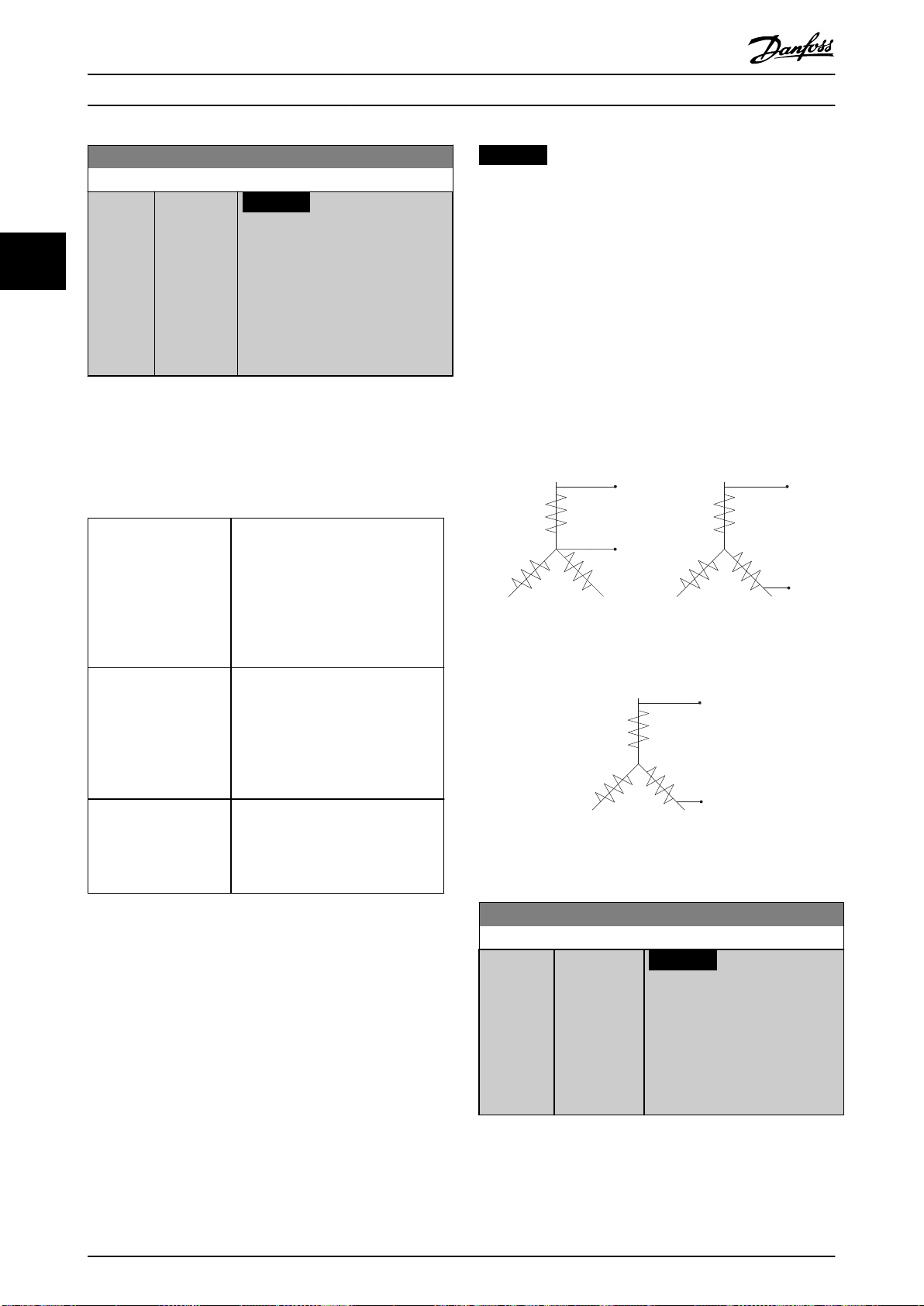
Line to common (starpoint)
Line to line values
Rs and Ld
Rs and Ld
130BC008.11
Permanent magnet motors
130BC009.10
Line to Line Back
Emf in RMS Value
at 1000 rpm
Speed (mech)
Parameter Description
VLT® Refrigeration Drive FC 103
1-37 d-axis Inductance (Ld)
Range: Function:
Size
related*
33
[0.000 -
1000.000
mH]
NOTICE
This parameter is only active
when parameter 1-10 Motor
Construction is set to [1] PM,
non-salient SPM.
NOTICE
Motor manufacturers provide values for stator resistance
(parameter 1-30 Stator Resistance (Rs)) and d-axis
inductance (parameter 1-37 d-axis Inductance (Ld)) in
technical specications as between line and common
(startpoint) or line between line. There is no general
standard. The dierent set-ups of stator winding
resistance and induction are shown in Illustration 3.6.
Danfoss frequency converters always require the line-to-
Enter the value of the d-axis
inductance. Obtain the value from the
PM motor datasheet.
For asynchronous motor, stator resistance, and d-axis
inductance values are normally described in technical
specications as between line and common (startpoint).
common value. The back EMF of a PM motor is dened
as induced EMF developed across any of 2 phases of
stator winding of a free-running motor. Danfoss
frequency converters always require the line-to-line RMS
value measured at 1000 RPM, mechanical speed of
rotation. This is shown in Illustration 3.7).
For PM motors, they are typically described in technical
specications as between line-line. PM motors are typically
built for star connection.
Parameter 1-30 Stator
Resistance (Rs)
(line to common).
Parameter 1-37 d-axis
Inductance (Ld)
(line to common).
Parameter 1-40 Back EMF
at 1000 RPM
RMS (line to line value).
This parameter gives stator winding
resistance (Rs) similar to asynchronous
motor stator resistance. The stator
resistance is dened for line-tocommon measurement. For line-line
data, where stator resistance is
measured between any 2 lines, divide
by 2.
This parameter gives direct axis
inductance of the PM motor. The daxis inductance is dened for phaseto-common measurement. For lineline data, where stator resistance is
measured between any 2 lines, divide
by 2.
This parameter gives back EMF across
stator terminal of PM motor at 1000
RPM mechanical speed specically. It
is dened between line-to-line and
expressed in RMS value.
Illustration 3.6 Stator Winding Set-ups
Illustration 3.7 Machine Parameter Denitions of Back EMF of
PM Motors
Table 3.4 Parameters Related to PM Motors
42 Danfoss A/S © 05/2016 All rights reserved. MG16H202
1-38 q-axis Inductance (Lq)
Range: Function:
Size related* [0.000 - 1000
mH]
NOTICE
This parameter cannot be
adjusted while the motor is
running.
Set the value of the q-axis
inductance. See the motor
datasheet.
Page 45

Parameter Description Programming Guide
1-39 Motor Poles
Range: Function:
Size
related*
[2 -
NOTICE
100]
This parameter cannot be adjusted
while the motor is running.
Enter the number of motor poles.
Poles ~nn@ 50 Hz ~nn@ 60 Hz
2 2700–2880 3250–3460
4 1350–1450 1625–1730
6 700–960 840–1153
Table 3.5 Pole Counts and Related
Frequencies
Table 3.5 shows the pole numbers for normal
speed ranges of various motor types. Dene
motors designed for other frequencies
separately. The motor pole value is always an
even number, because it refers to the total
pole numbers, not pairs of poles. The
frequency converter creates the initial setting
of parameter 1-39 Motor Poles based on
parameter 1-23 Motor Frequency and
parameter 1-25 Motor Nominal Speed.
1-40 Back EMF at 1000 RPM
Range: Function:
Size
related*
[ 10 9000 V]
Set the nominal back EMF for the motor
when running at 1000 RPM. This
parameter is only active when
parameter 1-10 Motor Construction is set
to [1] PM, non salient SPM.
1-41 Motor Angle Oset
Range: Function:
0* [-32768 -
32767]
Enter the correct oset angle between the PM
motor and the index position (single-turn) of the
attached encoder or resolver. The value range of
0–32768 corresponds to 0–2 x pi (radians).
This parameter is only active when
parameter 1-10 Motor Construction is set to [1]
PM, non-salient SPM (Permanent Magnet Motor).
1-44 d-axis Inductance Sat. (LdSat)
Range: Function:
Size
related*
[0 1000 mH]
Enter the inductance saturation of Ld.
Ideally, this parameter has the same
value as parameter 1-37 d-axis Inductance
(Ld). If the motor supplier provides an
induction curve, enter the induction
value at 200% of the nominal value.
1-45 q-axis Inductance Sat. (LqSat)
Range: Function:
Size
related*
[0 1000 mH]
This parameter corresponds to the
inductance saturation of Lq. Ideally, this
parameter has the same value as
parameter 1-38 q-axis Inductance (Lq). If
the motor supplier provides an induction
curve, enter the induction value at 200%
of the nominal value.
1-46 Position Detection Gain
Range: Function:
100 %* [20 -
200 %]
Adjusts the amplitude of the test pulse
during position detection at start. Adjust
this parameter to improve the position
measurement.
1-47 Torque Calibration
Option: Function:
Use this parameter to optimize the torque estimate
in the full speed range. The estimated torque is
based on the shaft power, P
sure that the Rs value is correct. The Rs value in this
formula is equal to the power loss in the motor, the
cable, and the frequency converter. When this
parameter is active, the frequency converter
calculates the Rs value during power-up, ensuring
the optimal torque estimate and optimal
performance. Use this feature in cases when it is not
possible to adjust parameter 1-30 Stator Resistance
(Rs) on each frequency converter to compensate for
the cable length, frequency converter losses, and
the temperature deviation on the motor.
[0] O
[1] 1st
start
after
pwr-up
[2] Every
start
[3] 1st
start
with
store
[4] Every
start
with
store
Calibrates at the rst start-up after power-up and
keeps this value until reset by a power cycle.
Calibrates at every start-up, compensating for a
possible change in motor temperature since last
start-up. The value is reset after a power cycle.
The frequency converter calibrates the torque at the
rst start-up after power-up. This option is used to
update motor parameters:
Parameter 1-30 Stator Resistance (Rs).
•
Parameter 1-37 d-axis Inductance (Ld).
•
The frequency converter calibrates the torque at
every start-up, compensating for a possible change
in motor temperature since last start-up. This option
is used to update motor parameters:
Parameter 1-30 Stator Resistance (Rs).
•
Parameter 1-37 d-axis Inductance (Ld).
•
= Pm - Rs x I2. Make
shaft
3 3
MG16H202 Danfoss A/S © 05/2016 All rights reserved. 43
Page 46

Magn. current
130BA045.11
Hz
Par.1-50
Par.1-51
100%
Par.1-52 RPM
Parameter Description
VLT® Refrigeration Drive FC 103
3.3.7 1-5* Load Indep. Setting
33
44 Danfoss A/S © 05/2016 All rights reserved. MG16H202
1-48 Inductance Sat. Point
Range: Function:
Size related* [1 - 500 %] Enter the induction saturation point.
1-50 Motor Magnetisation at Zero Speed
This parameter is not visible on the LCP.
Range: Function:
100 %* [0 -
300 %]
NOTICE
Parameter 1-50 Motor Magnetisation at
Zero Speed has no eect when
parameter 1-10 Motor Construction = [1]
PM, non-salient SPM.
Use this parameter along with
parameter 1-51 Min Speed Normal Magnetising
[RPM] to obtain a dierent thermal load on the
motor when running at low speed.
Enter a value which is a percentage of the rated
magnetizing current. If the setting is too low,
the torque on the motor shaft may be reduced.
Illustration 3.8 Motor Magnetization
1-51 Min Speed Normal Magnetising [RPM]
This parameter is not visible on the LCP.
Range: Function:
Size
related*
[10 300 RPM]
NOTICE
Parameter 1-51 Min Speed Normal
Magnetising [RPM] has no eect
when parameter 1-10 Motor
Construction=[1] PM, non-salient
SPM.
Set the required speed for normal
magnetizing current. If the speed is set
lower than the motor slip speed,
parameter 1-50 Motor Magnetisation at
Zero Speed and parameter 1-51 Min Speed
Normal Magnetising [RPM] are of no
signicance.
Use this parameter along with
parameter 1-50 Motor Magnetisation at
Zero Speed. See Table 3.5.
1-52 Min Speed Normal Magnetising [Hz]
This parameter is not visible on the LCP.
Range: Function:
Size
related*
[ 0.3 -
10.0 Hz]
NOTICE
Parameter 1-52 Min Speed Normal
Magnetising [Hz] has no eect when
parameter 1-10 Motor Construction =
[1] PM, non-salient SPM.
Set the required frequency for normal
magnetizing current. If the frequency is
set lower than the motor slip frequency,
parameter 1-50 Motor Magnetisation at
Zero Speed and parameter 1-51 Min Speed
Normal Magnetising [RPM] are inactive.
Use this parameter along with
parameter 1-50 Motor Magnetisation at
Zero Speed. See Table 3.5.
1-58 Flying Start Test Pulses Current
Range: Function:
Size
related*
[ 0 -
Set the magnitude of the magnetizing
200 %]
current for the pulses used to detect the
motor direction. Higher values result in more
accurate results when the frequency
converter is oversized compared to the
motor. The value range and function depend
on parameter 1-10 Motor Construction:
[0] Asynchron: [0-200%]
Reducing this value reduces the generated
torque. 100% means full nominal motor
current. In this case, the default value is 30%.
[1] PM non salient: [0-40%].
A general setting of 20% is recommended on
PM motors. Higher values can give increased
performance. However, on motors with back
EMF higher than 300 VLL (rms) at nominal
speed and high winding inductance (more
than 10 mH) a lower value is recommended
to avoid wrong speed estimation. The
parameter is active when
parameter 1-73 Flying Start is enabled.
1-59 Flying Start Test Pulses Frequency
Range: Function:
Size
related*
[ 0 500 %]
NOTICE
See description of parameter 1-70 PM
Start Mode for an overview of the
relation between the PM Flying Start
parameters.
The parameter is active when
parameter 1-73 Flying Start is enabled. The
value range and function depend on
parameter 1-10 Motor Construction:
Page 47

130BA046.11
60%
0%
100%
U
m
Changeover
f
out
Par.1-60 Par.1-61
Parameter Description Programming Guide
1-59 Flying Start Test Pulses Frequency
Range: Function:
[0] Asynchron: [0-500%]
Control the percentage of the frequency for
the pulses used to detect the motor
direction. Increasing this value reduces the
generated torque. In this mode, 100% means
2 times the slip frequency.
[1] PM non salient: [0-10%]
This parameter denes the motor speed (in
% of nominal motor speed) below which the
parking function (see parameter 2-06 Parking
Current and parameter 2-07 Parking Time
becomes active). This parameter is only
active when parameter 1-70 PM Start Mode is
set to [1] Parking and only after starting the
motor.
3.3.8 1-6* Load Depend. Setting
1-60 Low Speed Load Compensation
This parameter is not visible on the LCP.
Range: Function:
100 %* [0 -
300 %]
NOTICE
Parameter 1-60 Low Speed Load
Compensation has no eect when
parameter 1-10 Motor Construction = [1]
PM, non-salient SPM.
Enter the % value to compensate voltage in
relation to load when the motor is running at
low speed, and obtain the optimum U/f
characteristic. The motor size determines the
frequency range within which this parameter
is active.
Illustration 3.9 Low Speed Load Compensation
1-61 High Speed Load Compensation
This parameter is not visible on the LCP.
Range: Function:
100 %* [0 -
300 %]
NOTICE
Parameter 1-61 High Speed Load
Compensation has no eect when
parameter 1-10 Motor Construction = [1]
PM, non-salient SPM.
Enter the % value to compensate voltage in
relation to load when the motor is running at
high speed, and obtain the optimum U/f
characteristic. The motor size determines the
frequency range within which this parameter
is active.
Motor size Change-over
1.1–7.5 kW >10 Hz
3 3
Motor size [kW] Change-over [Hz]
0.25–7.5 <10
11–45 <5
55–550 <3–4
Table 3.6 Low Speed Load Compensation
MG16H202 Danfoss A/S © 05/2016 All rights reserved. 45
1-62 Slip Compensation
Range: Function:
0 %* [-500 -
500 %]
NOTICE
Parameter 1-62 Slip Compensation has no
eect when parameter 1-10 Motor
Construction = [1] PM, non-salient SPM.
Enter the % value for slip compensation to
compensate for tolerances in the value of n
Slip compensation is calculated automatically,
that is on the basis of the rated motor speed
n
.
M,N
M,N
.
Page 48

Parameter Description
VLT® Refrigeration Drive FC 103
1-63 Slip Compensation Time Constant
Range: Function:
Size
related*
[0.05 5 s]
NOTICE
Parameter 1-63 Slip Compensation
Time Constant has no eect when
33
parameter 1-10 Motor Construction =
[1] PM, non-salient SPM.
Enter the slip compensation reaction
speed. A high value results in slow
reaction, and a low value results in quick
reaction. If low-frequency resonance
problems arise, use a longer time setting.
1-64 Resonance Dampening
Range: Function:
100%* [0 -
500 %]
NOTICE
Parameter 1-64 Resonance Dampening has
no eect when parameter 1-10 Motor
Construction=[1] PM, non-salient SPM.
Enter the resonance damping value. Set
parameter 1-64 Resonance Dampening and
parameter 1-65 Resonance Dampening Time
Constant to help eliminate high frequency
resonance problems. To reduce resonance
oscillation, increase the value of
parameter 1-64 Resonance Dampening.
1-65 Resonance Dampening Time Constant
Range: Function:
5 ms* [5 - 50
ms]
NOTICE
Parameter 1-65 Resonance Dampening
Time Constant has no eect when
parameter 1-10 Motor Construction = [1]
1-66 Min. Current at Low Speed
Range: Function:
Increasing this current improves developed
motor torque at low speed. Low speed is
here dened as speeds below 6% of the
nominal motor speed (parameter 1-25 Motor
Nominal Speed) in VVC+ PM Control.
3.3.9 1-7* Start Adjustments
1-70 PM Start Mode
Option: Function:
[0] Rotor
Detection
[1] * Parking If the motor turns at a low speed (that is
1-71 Start Delay
Range: Function:
00s* [0 -
300 s]
Suitable for all applications where the motor is
known to be standing still when starting (for
example conveyors, pumps, and non-wind
milling fans).
lower than 2–5% of the nominal speed), for
example due to fans with windmilling, select
[1] Parking and adjust parameter 2-06 Parking
Current and parameter 2-07 Parking Time
accordingly.
Enter the time delay between the start command
and the time when the frequency converter
supplies power to the motor.
This parameter is related to the start function
selected in parameter 1-72 Start Function.
The parameter is used for delayed start of
compressor functionality in injection control.
Parameter 28-91 Delayed Compressor Start controls
the delayed start feature. Set the start delay value
equal to or greater than the default value.
PM, non-salient SPM.
1-72 Start Function
Set parameter 1-64 Resonance Dampening and
parameter 1-65 Resonance Dampening Time
Constant to help eliminate high frequency
resonance problems. Enter the time constant
that provides the best dampening.
1-66 Min. Current at Low Speed
Range: Function:
Size
related*
[ 1 200 %]
NOTICE
Parameter 1-66 Min. Current at Low
Speed has no eect if
parameter 1-10 Motor Construction =
[0] Asynchron.
Enter the minimum motor current at low
speed.
Option: Function:
Select the start function during the start
delay. This parameter is linked to
parameter 1-71 Start Delay.
[0] DC Hold/
Motor
Preheat
[1] DC Brake Energises motor with a DC braking current
[2] Coast Releases shaft coasted converter during the
Energizes motor with a DC holding current
(parameter 2-00 DC Hold/Preheat Current)
during the start delay time.
(parameter 2-01 DC Brake Current) during the
start delay time.
start delay time (inverter o).
Available selections depend on
parameter 1-10 Motor Construction:
[0] Asynchron:
46 Danfoss A/S © 05/2016 All rights reserved. MG16H202
Page 49

Parameter Description Programming Guide
1-72 Start Function
Option: Function:
[2] Coast
[0] DC-hold
[1] PM non-salient:
[2] coast
[3] Start speed
cw
[5] VVC+/Flux
clockwise
1-73 Flying Start
Option: Function:
This function enables catching a motor which is
spinning freely due to a mains drop-out.
When parameter 1-73 Flying Start is enabled,
parameter 1-71 Start Delay has no function.
Search direction for ying start is linked to the
setting in parameter 4-10 Motor Speed Direction.
[0] Clockwise: Flying start searches in clockwise
direction. If not successful, a DC brake is activated.
[2] Both Directions: The ying start rst makes a
search in the direction determined by the last
reference (direction). If the speed is not found, it
makes a search in the other direction. If not
successful, a DC brake is activated in the time set
in parameter 2-02 DC Braking Time. Start then
takes place from 0 Hz.
[0] Disabled Select [0] Disable if this function is not required.
[1] Enabled Select [1] Enable to enable the frequency
converter to catch and control a spinning motor.
The parameter is always set to [1] Enable when
parameter 1-10 Motor Construction=[1] PM nonsalient.
Important related parameters:
Parameter 1-58 Flying Star t Test Pulses
•
Current
Parameter 1-59 Flying Star t Test Pulses
•
Frequency
Parameter 1-70 PM Start Mode
•
Parameter 2-06 Parking Current
•
Parameter 2-07 Parking Time
•
Parameter 2-03 DC Brake Cut In Speed
•
[RPM]
Parameter 2-04 DC Brake Cut In Speed [Hz]
•
Parameter 2-06 Parking Current
•
Parameter 2-07 Parking Time
•
[2] Enabled
Always
[3] Enabled
Ref. Dir.
1-73 Flying Start
Option: Function:
[4] Enab.
Always
Ref. Dir.
The ying-start function used for PM motors is based on
an initial speed estimation. The speed is always estimated
as the rst thing after an active start signal is given. Based
on the setting of parameter 1-70 PM Start Mode the
following happens:
Parameter 1-70 PM Start Mode=[0] Rotor Detection:
If the speed estimate appears as greater than 0 Hz, the
frequency converter catches the motor at that speed and
resumes normal operation. Otherwise, the frequency
converter estimates the rotor position and start normal
operation from there.
Parameter 1-70 PM Start Mode=[1] Parking:
A speed estimate lower than the setting in
parameter 1-59 Flying Start Test Pulses Frequency engages
the parking function (see parameter 2-06 Parking Current
and parameter 2-07 Parking Time). Otherwise, the frequency
converter catches the motor at that speed and resumes
normal operation. Refer to the description of
parameter 1-70 PM Start Mode for recommended settings.
Current limitations of the ying-start principle used for PM
motors:
The speed range is up to 100% nominal speed or
•
the eld weakening speed (whichever is lowest).
PMSM with high back EMF (>300 VLL(rms)) and
•
high winding inductance (>10 mH) needs more
time for reducing short-circuit current to 0 and
may be susceptible to error in estimation.
Current testing limited to a speed range up to
•
300 Hz. For certain units, the limit is 250 Hz; all
200–240 V units up to and including 2.2 kW
(3 hp) and all 380–480 V units up to and
including 4 kW (5 hp).
For high-inertia applications (that is, where the
•
load inertia is more than 30 times larger than the
motor inertia), use a brake resistor to avoid
overvoltage trip during high-speed engagement
of the ying-start function.
1-74 Start Speed [RPM]
Range: Function:
Size
related*
[0 600
RPM]
Set a motor start speed. After the start
signal, the output speed leaps to set value.
Set the start function in
parameter 1-72 Start Function to [3] Start
speed cw, [4] Horizontal operation, or [5] VVC
+
/Flux clockwise, and set a start delay time
in parameter 1-71 Start Delay.
3 3
MG16H202 Danfoss A/S © 05/2016 All rights reserved. 47
Page 50

Parameter Description
VLT® Refrigeration Drive FC 103
1-75 Start Speed [Hz]
Range: Function:
Size
related*
33
[ 0 -
500.0
Hz]
This parameter can be used for hoist
applications (cone rotor). Set a motor start
speed. After the start signal, the output
speed leaps to the set value. Set the start
function in parameter 1-72 Start Function to
[3] Start speed cw, [4] Horizontal operation, or
[5] VVC+/Flux clockwise, and set a start delay
time in parameter 1-71 Start Delay.
1-76 Start Current
Range: Function:
0A* [ 0 -
par.
1-24 A]
Some motors, for example cone rotor motors,
need extra current/starting speed to disengage
the rotor. To obtain this boost, set the required
current in parameter 1-76 Start Current. Set
parameter 1-74 Start Speed [RPM]. Set
parameter 1-72 Start Function to [3] Start speed cw
or [4] Horizontal operation, and set a start delay
time in parameter 1-71 Start Delay.
This parameter can be used for hoist applications
(cone rotor).
1-77 Compressor Start Max Speed [RPM]
Range: Function:
Trip is exceeded, the frequency converter trips
with alarm 18, Star t failed.
When this function is activated to get a fast
start, parameter 1-86 Compressor Min. Speed for
Trip [RPM] is also activated to protect the
application from running below minimum
motor speed, for example when in current
limit.
This function allows high starting torque and
use of a fast starting ramp. To ensure the
build-up of a high torque during the start,
enter appropriate values for start delay/start
speed/start current.
1-78 Compressor Start Max Speed [Hz]
Range: Function:
Size
related*
[ 0 -
NOTICE
par.
Parameter 1-78 Compressor Start Max
4-14
Speed [Hz] has no eect when
Hz]
parameter 1-10 Motor Construction = [1]
PM, non-salient SPM.
1-77 Compressor Start Max Speed [RPM]
Range: Function:
Size
related*
[ 0 -
NOTICE
par.
Parameter 1-77 Compressor Start Max
4-13
Speed [RPM] has no eect when
RPM]
parameter 1-10 Motor Construction = [1]
PM, non-salient SPM.
The parameter enables high starting torque.
This is a function, where the current limit and
torque limit are ignored during start of the
motor. The time from the start signal is given
until the speed exceeds the speed set in this
parameter, becomes a start-zone where the
current limit and motoric torque limit is set to
what is maximum possible for the frequency
converter/motor combination. This parameter
is normally set to the same value as
parameter 4-11 Motor Speed Low Limit [RPM].
When set to 0, the function is inactive.
In this starting-zone, parameter 3-82 Starting
Ramp Up Time is active to ensure extra
acceleration during the start and to minimize
the time where the motor is operated under
the minimum speed for the application. The
time without protection from the current limit
and torque limit must not exceed the value
set in parameter 1-79 Compressor Start Max
Time to Trip. If the value in
parameter 1-79 Compressor Start Max Time to
The parameter enables high starting torque.
This is a function, where the current limit and
torque limit are ignored during start of the
motor. The time, from the start signal is given
until the speed exceeds the speed set in this
parameter, becomes a start-zone where the
current limit and motoric torque limit is set to
what is maximum possible for the frequency
converter/motor combination. This parameter
is normally set to the same value as
parameter 4-11 Motor Speed Low Limit [RPM].
When set to 0, the function is inactive.
In this starting-zone, parameter 3-82 Starting
Ramp Up Time is active instead of
parameter 3-41 Ramp 1 Ramp Up Time to
ensure extra acceleration during the start, and
to minimize the time where the motor is
operated under the minimum speed for the
application. The time without protection from
the current limit and torque limit must not
exceed the value set in
parameter 1-79 Compressor Start Max Time to
Trip. If the value of parameter 1-79 Compressor
Start Max Time to Trip is exceeded, the
frequency converter trips with alarm 18, Start
failed.
When this function is activated to get a fast
start, parameter 1-86 Compressor Min. Speed for
Trip [RPM] is also activated to protect the
application from running below minimum
motor speed, for example when in current
limit.
48 Danfoss A/S © 05/2016 All rights reserved. MG16H202
Page 51

Parameter Description Programming Guide
1-78 Compressor Start Max Speed [Hz]
Range: Function:
This function allows high starting torque and
use of a fast starting ramp. To ensure the
build-up of a high torque during the start,
enter appropriate values for start delay/start
speed/start current.
1-79 Compressor Start Max Time to Trip
Range: Function:
5 s* [0 -
NOTICE
10 s]
Parameter 1-79 Compressor Start Max Time to
Trip has no eect when parameter 1-10 Motor
Construction = [1] PM, non-salient SPM.
The time from the start signal is given until the
speed exceeds the speed set in
parameter 1-77 Compressor Start Max Speed [RPM]
must not exceed the time set in the parameter. If
the time set is exceeded, the frequency converter
trips with alarm 18, Start failed.
Any time set in parameter 1-71 Start Delay for use of
a start function must be executed within the time
limit.
3.3.10 1-8* Stop Adjustments
1-80 Function at Stop
Option: Function:
Select the frequency converter function after a
stop command or after the speed is ramped
down to the settings in parameter 1-81 Min
Speed for Function at Stop [RPM].
Available selections depend on
parameter 1-10 Motor Construction:
[0] Asynchronous:
[0] Coast
[1] DC hold
[2] Motor check, warning
[6] Motor check, alarm
[1] PM non-salient:
[0] Coast
[0] * Coast Leaves motor in free mode.
[1] DC Hold/
Motor
Preheat
1-81 Min Speed for Function at Stop [RPM]
Range: Function:
Size related* [0 - 600
Energizes motor with a DC hold current (see
parameter 2-00 DC Hold/Preheat Current).
Set the speed at which to activate
RPM]
parameter 1-80 Function at Stop.
1-82 Min Speed for Function at Stop [Hz]
Range: Function:
Size related* [ 0 - 20.0
Hz]
Set the output frequency at which to
activate parameter 1-80 Function at
Stop.
1-86 Compressor Min. Speed for Trip [RPM]
Range: Function:
Size
related*
[ 0 1500
RPM]
NOTICE
This parameter is only available if
parameter 0-02 Motor Speed Unit is set
to [11] RPM.
Enter the low limit for the motor speed at
which the frequency converter trips. If the
value is 0, the function is not active. If the
speed at any time after the start (or during
a stop) drops below the value in the
parameter, the frequency converter trips
with alarm 49, Speed Limit.
1-87 Compressor Min. Speed for Trip [Hz]
Range: Function:
Size
related*
[ 0 -
NOTICE
50 Hz]
This parameter is only available if
parameter 0-02 Motor Speed Unit is set
to [1] Hz.
Enter the low limit for the motor speed at
which the frequency converter trips. If the
value is 0, the function is not active. If the
speed at any time after the start (or during a
stop) drops below the value in the
parameter, the frequency converter trips with
alarm 49, Speed Limit.
3.3.11 1-9* Motor Temperature
NOTICE
When using multiple motors, the electronic thermal relay
on the frequency converter cannot be used to provide
individual motor protection. Supply a separate motor
overload for each motor.
1-90 Motor Thermal Protection
Option: Function:
The frequency converter determines the
motor temperature for motor overload
protection in 2 dierent ways:
Via a thermistor sensor connected
•
to 1 of the analog or digital inputs
(parameter 1-93 Thermistor Source).
3 3
MG16H202 Danfoss A/S © 05/2016 All rights reserved. 49
Page 52

1.21.0 1.4
30
10
20
100
60
40
50
1.81.6 2.0
2000
500
200
400
300
1000
600
t [s]
175ZA052.12
f
OUT
= 2 x f
M,N
f
OUT
= 0.2 x f
M,N
f
OUT
= 1 x f
M,N
(par. 1-23)
IMN(par. 1-24)
I
M
Parameter Description
VLT® Refrigeration Drive FC 103
1-90 Motor Thermal Protection
Option: Function:
See chapter 3.3.12.1 PTC Thermistor
Connection.
Via calculation (ETR=electronic
•
33
[0] No
protection
[1] Thermistor
warning
[2] Thermistor
trip
[3] ETR warning
1
[4] ETR trip 1
[5] ETR warning
2
[6] ETR trip 2
[7] ETR warning
3
[8] ETR trip 3
[9] ETR warning
4
[10] ETR trip 4
If the motor is continuously overloaded, and
no warning or trip of frequency converter is
wanted.
Activates a warning when the connected
thermistor in the motor reacts in the event of
motor overtemperature.
Stops (trips) the frequency converter when
the connected thermistor in the motor reacts
in the event of motor overtemperature.
thermal relay) of the thermal load,
based on the actual load and time.
The calculated thermal load is
compared with the rated motor
current I
frequency f
estimate the need for a lower load
at lower speed due to less cooling
from the fan incorporated in the
motor. See chapter 3.3.12.2 ETR.
Via a mechanical thermal switch
•
(Klixon type). See
chapter 3.3.12.3 Klixon. The ETR
provides class 20 motor overload
protection in accordance with NEC.
and the rated motor
M,N
. The calculations
M,N
Illustration 3.10 Thermal Motor Protection
NOTICE
If the temperature of the motor is monitored through a
thermistor or a KTY Sensor, the PELV is not complied
with in case of short circuits between motor windings
and the sensor. To comply with PELV, isolate the sensor
appropriately.
NOTICE
Danfoss recommends using 24 V DC as thermistor supply
voltage.
NOTICE
The ETR timer function does not work when
parameter 1-10 Motor Construction=[1] PM, non-salient
SPM.
NOTICE
For correct operation of the ETR function, the setting in
parameter 1-03 Torque Characteristics must t the
application (see description of parameter 1-03 Torque
Characteristics).
ETR functions 1-4 calculate the load when the set-up
where they were selected is active. For example ETR-3
starts calculating when set-up 3 is selected. For the North
American market: The ETR functions provide class 20
motor overload protection in accordance with NEC.
50 Danfoss A/S © 05/2016 All rights reserved. MG16H202
Page 53

1330
550
250
-20 °C
175HA183.11
4000
3000
R
(Ω)
nominal
nominal -5 °C nominal +5 °C
[°C]
PTC / Thermistor
R
OFF
ON
<800 Ω
+10V
130BA152.10
>2.7 kΩ
12 13 18 37322719 29 33 20
5550
39 42 53 54
555039 42 53 54
R
<3.0 k Ω
>3.0 k Ω
+10V
130BA153.11
PTC / Thermistor
OFF
ON
1.21.0 1.4
30
10
20
100
60
40
50
1.81.6 2.0
2000
500
200
400
300
1000
600
t [s]
175ZA052.12
f
OUT
= 2 x f
M,N
f
OUT
= 0.2 x f
M,N
f
OUT
= 1 x f
M,N
(par. 1-23)
IMN(par. 1-24)
I
M
Parameter Description Programming Guide
3.3.12.1 PTC Thermistor Connection
3 3
Illustration 3.13 PTC Thermistor Connection - Analog Input
Illustration 3.11 PTC Prole
Example using a digital input and 10 V as supply
The frequency converter trips when the motor temperature
is too high.
Parameter set-up:
Set parameter 1-90 Motor Thermal Protection to [2]
•
Thermistor Trip.
Set parameter 1-93 Thermistor Source to [6] Digital
•
Input.
Input
digital/analog
Digital 10
Analog 10
Table 3.7 Threshold Cutout Values
Supply voltage
[V]
Threshold
cutout values.
<800 Ω⇒2.7 kΩ
<3.0 kΩ⇒3.0 kΩ
NOTICE
Check that the selected supply voltage follows the
specication of the used thermistor element.
3.3.12.2 ETR
The calculations estimate the need for a lower load at
lower speed due to less cooling from the fan incorporated
in the motor.
Illustration 3.12 PTC Thermistor Connection - Digital Input
Example using an analog input and 10 V as supply
The frequency converter trips when the motor temperature
is too high.
Parameter set-up:
MG16H202 Danfoss A/S © 05/2016 All rights reserved. 51
Set parameter 1-90 Motor Thermal Protection to [2]
•
Thermistor Trip.
Set parameter 1-93 Thermistor Source to [2] Analog
•
Input 54.
Illustration 3.14 ETR Prole
Page 54

PTC / Thermistor
OFF
ON
+24V
12 13 18 3732
A
2719 29 33B20
GND
R<6.6 k Ω >10.8 k Ω
130BA151.11
Parameter Description
VLT® Refrigeration Drive FC 103
3.3.12.3 Klixon
The Klixon type thermal circuit breaker uses a KLIXON
metal dish. At a predetermined overload, the heat caused
by the current through the disc causes a trip.
33
Example using a digital input and 24 V as supply
The frequency converter trips when the motor temperature
is too high.
Parameter set-up:
Set parameter 1-90 Motor Thermal Protection to [2]
•
Thermistor Trip.
Set parameter 1-93 Thermistor Source to [6] Digital
•
Input.
Illustration 3.15 Thermistor Connection
®
1-93 Thermistor Source
Option: Function:
parameter 3-16 Reference 2 Source, or
parameter 3-17 Reference 3 Source).
When using VLT® PTC Thermistor Card MCB
112, always select [0] None.
[0] * None
[1] Analog
Input 53
[2] Analog
Input 54
[3] Digital input
18
[4] Digital input
19
[5] Digital input
32
[6] Digital input
33
1-91 Motor External Fan
Option: Function:
[0] * No No external fan is required, that is the motor is
derated at low speed.
[1] Yes Applies an external motor fan (external ventilation), so
no derating of the motor is required at low speed. The
upper curve in Illustration 3.14 (f
followed if the motor current is lower than nominal
motor current (see parameter 1-24 Motor Current). If
the motor current exceeds nominal current, the
operation time still decreases as if no fan was
installed.
= 1 x f
out
M,N
) is
1-93 Thermistor Source
Option: Function:
NOTICE
This parameter cannot be adjusted
while the motor is running.
NOTICE
Set digital input to [0] PNP - Active at
24 V in parameter 5-00 Digital I/O Mode.
52 Danfoss A/S © 05/2016 All rights reserved. MG16H202
Select the input to which the thermistor (PTC
sensor) should be connected. An analog
input option [1] Analog Input 53 or [2] Analog
Input 54 cannot be selected if the analog
input is already in use as a reference source
(selected in parameter 3-15 Reference 1 Source,
Page 55

Parameter Description Programming Guide
3.4 Parameters: 2-** Brakes
3.4.1 2-0* DC brakes
Parameter group for conguring the DC brake and DC hold
functions.
2-00 DC Hold/Preheat Current
Range: Function:
50%* [ 0 -
NOTICE
160 %
Parameter 2-00 DC Hold/Preheat Current has
]
no eect when parameter 1-10 Motor
Construction=[1] PM, non-salient SPM.
NOTICE
The maximum value depends on the rated
motor current.
Avoid 100% current for too long. It may
damage the motor.
Enter a value for holding current as a percentage
of the rated motor current I
parameter 1-24 Motor Current. 100% DC hold
current corresponds to I
This parameter holds the motor (holding torque)
or preheats the motor.
This parameter is active if [1] DC hold/Motor
Preheat is selected in parameter 1-80 Function at
Stop.
M,N
.
M,N
set in
2-02 DC Braking Time
Range: Function:
10 s* [0 - 60 s] Set the duration of the DC brake current set in
parameter 2-01 DC Brake Current, once
activated.
2-03 DC Brake Cut In Speed [RPM]
Range: Function:
Size
related*
[ 0 - 0
RPM]
Set the DC brake cut-in speed for
activation of the DC braking current set
in parameter 2-01 DC Brake Current, upon
a stop command.
When parameter 1-10 Motor Construction
is set to [1] PM non-salient SPM, this value
is limited to 0 RPM (OFF).
2-04 DC Brake Cut In Speed [Hz]
Range: Function:
Size
related*
[ 0 -
0.0 Hz]
NOTICE
Parameter 2-04 DC Brake Cut In
Speed [Hz] is not eective when
parameter 1-10 Motor Construction =
[1] PM, non-salient SPM.
Set the DC brake cut-in speed for
activation of the DC brake current set in
parameter 2-01 DC Brake Current after a
stop command.
3 3
2-01 DC Brake Current
Range: Function:
50%* [ 0 -
1000 %
]
NOTICE
The maximum value depends on the rated
motor current. Avoid 100% current for too
long. It may damage the motor.
Enter a value for current as a percentage of the
rated motor current I
Current. 100% DC brake current corresponds to
I
.
M,N
DC brake current is applied on a stop command,
when the speed is lower than the limit set in:
•
•
The braking current is active during the time
period set in parameter 2-02 DC Braking Time.
, see parameter 1-24 Motor
M,N
Parameter 2-03 DC Brake Cut In Speed
[RPM].
Parameter 2-04 DC Brake Cut In Speed
[Hz], when the DC brake inverse function
is active, or via the serial communication
port.
2-06 Parking Current
Range: Function:
50%* [ 0 -
1000 %]
NOTICE
Parameter 2-06 Parking Current and
parameter 2-07 Parking Time: Only active
if [1] PM, non salient SPM is selected in
parameter 1-10 Motor Construction.
Set current as percentage of rated motor
current, parameter 1-24 Motor Current. Active in
connection with parameter 1-73 Flying Start. The
parking current is active during the time period
set in parameter 2-07 Parking Time.
2-07 Parking Time
Range: Function:
3 s* [0.1 - 60s]Set the duration of the parking current time set
in parameter 2-06 Parking Current. Active in
connection with parameter 1-73 Flying Start.
NOTICE
Parameter 2-07 Parking Time is only active
when [1] PM, non-salient SPM is selected
in parameter 1-10 Motor Construction.
MG16H202 Danfoss A/S © 05/2016 All rights reserved. 53
Page 56

Parameter Description
VLT® Refrigeration Drive FC 103
3.4.2 2-1* Brake Energy Funct.
Parameter group for selecting dynamic brake parameters.
Only valid for frequency converters with brake chopper.
2-10 Brake Function
33
Option: Function:
Available options depend on parameter 1-10 Motor
Construction:
[0] Asynchron:
[0] O
•
[1] Resistor brake
•
[2] AC brake
•
[1] PM non-salient:
[0] O
•
[1] Resistor brake
•
[0] O No brake resistor installed.
[1] Resistor
brake
[2] AC brake AC brake only works in compressor torque mode
Brake resistor incorporated in the system for
dissipation of excess brake energy as heat.
Connecting a brake resistor allows a higher DClink voltage during braking (generating operation).
The resistor brake function is only active in
frequency converters with an integral dynamic
brake.
in parameter 1-03 Torque Characteristics.
2-16 AC brake Max. Current
Range: Function:
100 %* [ 0 -
1000.0 %]
2-17 Over-voltage Control
Overvoltage control (OVC) reduces the risk of the frequency
converter tripping due to an overvoltage on the DC link caused
by generative power from the load.
Option: Function:
NOTICE
Parameter 2-16 AC brake Max.
Current has no eect when
parameter 1-10 Motor Construction =
[1] PM, non-salient SPM.
Enter the maximum permissible current
when using AC brake to avoid
overheating of motor windings.
NOTICE
The ramp time is automatically adjusted to
avoid tripping of the frequency converter.
[0] Disabled No OVC required.
[2] * Enabled Activates OVC.
54 Danfoss A/S © 05/2016 All rights reserved. MG16H202
Page 57

[P 5-13=Preset ref. bit 0]
Preset
[P 5-14=Preset ref. bit 1]
[P 5-15=Preset ref. bit 2]
10101010
76543210
29
12
(+24V)
11001100
32
11110000
33
130BA149.10
Parameter Description Programming Guide
3.5 Parameters: 3-** Reference/Ramps
3.5.1 3-0* Reference Limits
3-02 Minimum Reference
Range: Function:
Size
related*
[ -999999.999 par. 3-03
ReferenceFeedbackUnit]
Enter the minimum reference. The
minimum reference is the lowest
value obtainable by summing all
references. The minimum reference
value and unit match the congu-
ration made in
parameter 1-00 Conguration Mode
and parameter 20-12 Reference/
Feedback Unit.
NOTICE
This parameter is used in open
loop only.
3-03 Maximum Reference
Range: Function:
Size
related*
[ par. 3-02 -
999999.999
ReferenceFeedbackUnit]
Enter the maximum reference. The
maximum reference is the highest
value obtainable by summing all
references.
The maximum reference unit
matches the conguration selected
in parameter 1-00 Conguration
Mode: For [1] Speed closed loop,
RPM; for [2] Torque, Nm.
If [9] Positioning is selected in
parameter 1-00 Conguration Mode,
this parameter denes the default
speed for positioning.
3-04 Reference Function
Option: Function:
[0] * Sum Sums both external and preset reference
sources.
[1] External/
Preset
Use either the preset or the external
reference source.
Shift between external and preset via a
command or a digital input.
3.5.2 3-1* References
Select the preset reference(s). Select Preset ref. bit 0/1/2
[16], [17], or [18] for the corresponding digital inputs in
parameter group 5-1* Digital Inputs.
3-10 Preset Reference
Array [8]
Range: Function:
0 %* [-100 -
100 %]
Enter up to 8 dierent preset references (0-7) in
this parameter, using array programming. The
preset reference is stated as a percentage of the
value Ref
When using preset references, select preset
reference bit 0/1/2 [16], [17], or [18] for the
corresponding digital inputs in parameter group
5-1* Digital Inputs.
(parameter 3-03 Maximum Reference).
MAX
3 3
Illustration 3.16 Preset Reference Scheme
MG16H202 Danfoss A/S © 05/2016 All rights reserved. 55
Page 58

Preset relative ref.
Preset ref.Ref. 1 source
Ext. closed loop outputs
No function
Analog inputs
Frequency inputs
No function
No function
Freeze ref.
Speed up/ speed down
ref.
Remote
Ref. in %
[1]
[2]
[3]
[4]
[5]
[6]
[7]
Open loop
Freeze ref.
&
increase/
decrease
ref.
Scale to
RPM,Hz
or %
Scale to
Closed
loop
unit
Relative
X+X*Y
/100
DigiPot
DigiPot
DigiPot
max ref.
min ref.
[0]
on
o
Conguration mode
Closed loop
Input command:
Ref. function
Ref. Preset
Input command:
Preset ref. bit0, bit1, bit2
External
reference
in %
Bus
reference
Open loop
From Feedback Handling
Setpoint
Conguration mode
Input command:
Input command:
Digipot ref.
Increase
Decrease
Clear
DigiPot
Closed loop
Ref. 2 sourceRef. 3 source
Analog inputs
Frequency inputs
Analog inputs
Frequency inputs
Ext. closed loop outputs
Ext. closed loop outputs
P 3-10P 3-15P 3-16P 3-17
Y
X
%
%
P 1-00
P 3-14
±100%
130BA357.12
P 3-04
±200%
±200%
±200%
0%
±200%
P 1-00
±200%
0/1
0/1
0/1
Parameter Description
VLT® Refrigeration Drive FC 103
33
Hand / Auto
H/A MCO
Select which reference site to activate.
Use local reference when in hand-on mode,
or remote reference when in auto-on mode.
and auto-on mode.
and auto-on mode.
NOTICE
When set to [2] Local, the frequency
converter starts with this setting again
after a power-down.
For information, see VLT® Motion Control
MCO 305 Operating Instructions.
Illustration 3.17 Example of Open-loop Operation and Closed-loop Operation
3-11 Jog Speed [Hz]
Range: Function:
Size
related*
56 Danfoss A/S © 05/2016 All rights reserved. MG16H202
[ 0 - par.
4-14 Hz]
The jog speed is a xed output speed at
which the frequency converter is running
when the jog function is activated.
See also parameter 3-19 Jog Speed [RPM]
and parameter 3-80 Jog Ramp Time.
3-13 Reference Site
Option: Function:
[0] * Linked to
[1] Remote Use remote reference in both hand-on mode
[2] Local Use local reference in both hand-on mode
[3] Linked to
Page 59

Relative
Z=X+X*Y/100
Resulting
actual
reference
Y
X
130BA059.12
Z
X
100
%
0-100
Z
Y
X+X*Y/100
P 3-14
130BA278.10
Parameter Description Programming Guide
3-14 Preset Relative Reference
Range: Function:
0 %* [-100
100 %]
Illustration 3.18 Preset Relative Reference
The actual reference, X, is increased or decreased
with the percentage Y, set in parameter 3-14 Preset
Relative Reference.
This results in the actual reference Z. Actual
reference (X) is the sum of the inputs selected in:
Parameter 3-15 Reference 1 Source.
•
Parameter 3-16 Reference 2 Source.
•
Parameter 3-17 Reference 3 Source.
•
Parameter 8-02 Control Source.
•
3-15 Reference 1 Source
Option: Function:
[7] Pulse input 29
[8] Pulse input 33
[20] Digital pot.meter
[21] Analog input
X30/11
[22] Analog input
X30/12
[23] Analog Input
X42/1
[24] Analog Input
X42/3
[25] Analog Input
X42/5
[30] Ext. Closed Loop
1
[31] Ext. Closed Loop
2
[32] Ext. Closed Loop
3
3-16 Reference 2 Source
Option: Function:
NOTICE
This parameter cannot be adjusted
while the motor is running.
3 3
Illustration 3.19 Actual Reference
3-15 Reference 1 Source
Option: Function:
NOTICE
This parameter cannot be adjusted
while the motor is running.
Select the reference input to be used for
the 1st reference signal:
•
•
•
Dene up to 3 dierent reference signals.
[0] No function
[1] * Analog Input 53
[2] Analog Input 54
The sum of these reference signals
denes the actual reference.
Parameter 3-15 Reference 1
Source.
Parameter 3-16 Reference 2
Source.
Parameter 3-17 Reference 3
Source.
[0] No function
[1] Analog Input 53
[2] Analog Input 54
[7] Pulse input 29
[8] Pulse input 33
[20] * Digital
pot.meter
[21] Analog input
X30/11
[22] Analog input
X30/12
[23] Analog Input
X42/1
[24] Analog Input
X42/3
Select the reference input to be used for
the 2nd reference signal:
Parameter 3-15 Reference 1
•
Source.
Parameter 3-16 Reference 2
•
Source.
Parameter 3-17 Reference 3
•
Source.
Dene up to 3 dierent reference
signals. The sum of these reference
signals denes the actual reference.
MG16H202 Danfoss A/S © 05/2016 All rights reserved. 57
Page 60

t
acc
t
dec
130BA169.11
P 3-*2
Ramp (X)
Down
Time (Dec)
P 4-13
High-limit
RPM
Reference
P 1-25
Motor
speed
P 4-11
Low limit
Time
P 3-*1
Ramp (X)Up
Time (Acc)
Parameter Description
VLT® Refrigeration Drive FC 103
33
3-16 Reference 2 Source
Option: Function:
[25] Analog Input
X42/5
[30] Ext. Closed
Loop 1
[31] Ext. Closed
Loop 2
[32] Ext. Closed
Loop 3
3-17 Reference 3 Source
Option: Function:
[0] * No function
[1] Analog Input 53
[2] Analog Input 54
[7] Pulse input 29
[8] Pulse input 33
[20] Digital pot.meter
[21] Analog input
X30/11
[22] Analog input
X30/12
[23] Analog Input
X42/1
[24] Analog Input
X42/3
[25] Analog Input
X42/5
[30] Ext. Closed Loop
1
[31] Ext. Closed Loop
2
[32] Ext. Closed Loop
3
NOTICE
This parameter cannot be adjusted
while the motor is running.
Select the reference input to be used for
the 3rd reference signal:
Parameter 3-15 Reference 1
•
Source.
Parameter 3-16 Reference 2
•
Source.
Parameter 3-17 Reference 3
•
Source.
Dene up to 3 dierent reference signals.
The sum of these reference signals
denes the actual reference.
3-19 Jog Speed [RPM]
Range: Function:
Size
related*
[ 0 par. 4-13
RPM]
Enter a value for the jog speed n
is a xed output speed. The frequency
converter runs at this speed when the jog
function is activated. The maximum limit is
dened in parameter 4-13 Motor Speed High
Limit [RPM].
See also parameter 3-11 Jog Speed [Hz] and
parameter 3-80 Jog Ramp Time.
JOG
, which
3.5.3 3-4* Ramp 1
Congure the ramp times for each of the 2 ramps
(parameter group 3-4* Ramp 1 and parameter group 3-5*
Ramp 2).
Illustration 3.20 Ramp 1
3-41 Ramp 1 Ramp Up Time
Range: Function:
Size
related*
[ 1.00
- 3600
s]
Enter the ramp-up time, that is the
acceleration time from 0 RPM–
parameter 1-25 Motor Nominal Speed. Select a
ramp-up time such that the output current
does not exceed the current limit in
parameter 4-18 Current Limit during ramping.
See ramp-down time in parameter 3-42 Ramp
1 Ramp Down Time.
par . 3 − 41 =
tacc × nnom par . 1 − 25
ref RPM
s
58 Danfoss A/S © 05/2016 All rights reserved. MG16H202
Page 61
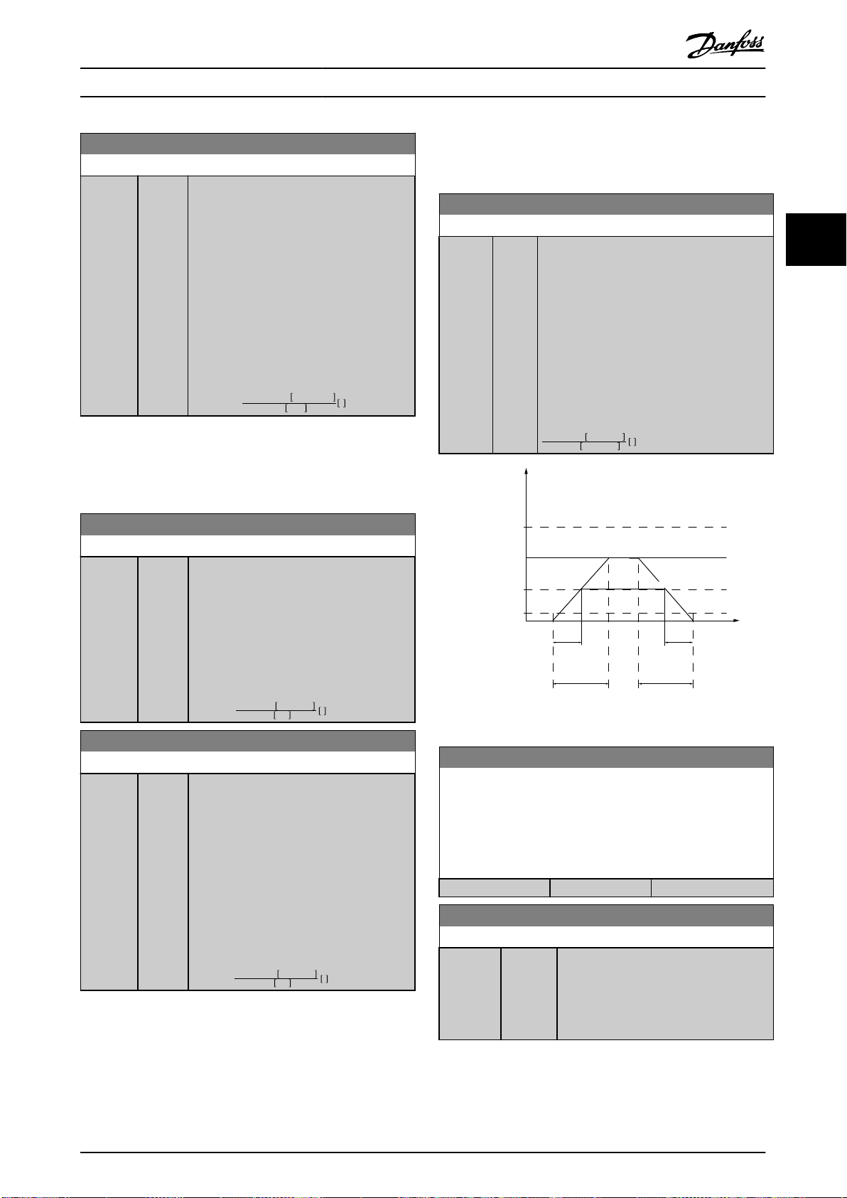
130BA070.10
Time
P 3-80
RPM
P 4-13 RPM
high limit
P 1-25
Motor speed
Jog speed
P 3-19
P 3-80
Ramp up
(acc)
Ramp down
(dec)
t jog t jog
P 4-11 RPM
low limit
Parameter Description Programming Guide
3-42 Ramp 1 Ramp Down Time
Range: Function:
Size
related*
[ 1.00 3600 s]
Enter the ramp-down time, that is the
deceleration time from
parameter 1-25 Motor Nominal Speed–0 RPM.
Select a ramp-down time preventing
overvoltage from arising in the inverter due
to regenerative operation of the motor. The
ramp-down time should also be long
enough to prevent that the generated
current exceeds the current limit set in
parameter 4-18 Current Limit. See ramp-up
time in parameter 3-41 Ramp 1 Ramp Up
Time.
par . 3 − 42 =
tdec × nnom par . 1 − 25
ref RPM
s
3.5.4 3-5* Ramp 2
To select ramp parameters, see parameter group 3-4* Ramp
1.
3-51 Ramp 2 Ramp Up Time
Range: Function:
Size
related*
[ 1.00 3600 s]
Enter the ramp-up time, that is the
acceleration time from 0 RPM–
parameter 1-25 Motor Nominal Speed. Select
a ramp-up time such that the output
current does not exceed the current limit in
parameter 4-18 Current Limit during
ramping. See ramp-down time in
parameter 3-52 Ramp 2 Ramp Down Time.
par . 3 − 51 =
tacc × nnom par . 1 − 25
ref rpm
s
3.5.5 3-8* Other Ramps
Parameters for conguring special ramps.
3-80 Jog Ramp Time
Range: Function:
Size
related*
Illustration 3.21 Jog Ramp Time
[1 3600 s]
Enter the jog ramp time, that is the
acceleration/deceleration time between 0 RPM
and the nominal motor speed (n
parameter 1-25 Motor Nominal Speed). Ensure
that the resulting output current required for
the given jog ramp time does not exceed the
current limit in parameter 4-18 Current Limit.
The jog ramp time starts after activating a jog
signal via the control panel, a selected digital
input, or the serial communication port.
par . 3 − 80 =
t jog × nnom par . 1 − 25
jog speed par . 3 − 19
s
) (set in
M,N
3 3
3-52 Ramp 2 Ramp Down Time
Range: Function:
Size
related*
MG16H202 Danfoss A/S © 05/2016 All rights reserved. 59
[ 1.00 3600 s]
Enter the ramp-down time, that is the
deceleration time from
parameter 1-25 Motor Nominal Speed–0 RPM.
Select a ramp-down time such that no
overvoltage occurs in the inverter due to
regenerative operation of the motor, and
such that the generated current does not
exceed the current limit set in
parameter 4-18 Current Limit. See ramp-up
time in parameter 3-51 Ramp 2 Ramp Up
Time.
tdec × nnom par . 1 − 25
par . 3 − 52 =
ref rpm
s
3-81 Quick Stop Ramp Time
Enter the quick stop ramp time. This is the acceleration/
deceleration time between 0 RPM and the rated motor frequency
in parameter 1-25 Motor Nominal Speed. During ramping, the
output current must not exceed the current limit in
parameter 4-18 Current Limit.
Range: Function:
Size related* [1 - 3600 s]
3-82 Starting Ramp Up Time
Range: Function:
Size
related*
[0.01 3600 s]
The ramp-up time is the acceleration time
from 0 RPM to the nominal motor speed
set in parameter 3-82 Starting Ramp Up
Time when [0] Compressor Torque is active
in parameter 1-03 Torque Characteristics.
Page 62

Speed
Time (s)
Inc
130BA158.11
P 3-95
Speed
Time (s)
Dec
Inc
130BA159.11
P 3-95
Parameter Description
VLT® Refrigeration Drive FC 103
3.5.6 3-9* Digital Pot.Meter
3-95 Ramp Delay
Range: Function:
Use the digital potentiometer function to increase or
decrease the actual reference by adjusting the set-up of
the digital inputs using the functions increase, decrease, or
clear. To activate the function, at least 1 digital input must
33
be set to increase or decrease.
3-90 Step Size
1* [0 -
3600]
Enter the delay required from activation of the
digital potentiometer function until the frequency
converter starts to ramp the reference. With a
delay of 0 ms, the reference starts to ramp as soon
as increase/decrease is activated. See also
parameter 3-91 Ramp Time.
Range: Function:
0.10 %* [0.01 -
200 %]
3-91 Ramp Time
Enter the increment size required for
increase/decrease as a percentage of the
synchronous motor speed, ns. If increase/
decrease is activated, the resulting reference
is increased or decreased by the value set in
this parameter.
Illustration 3.22 Ramp Delay Case 1
Range: Function:
1s [0 -
3600 s]
Enter the ramp time, that is the time for adjustment
of the reference 0–100% of the specied digital
potentiometer function (increase, decrease, or clear).
If increase/decrease is activated for longer than the
ramp delay period specied in parameter 3-95 Ramp
Delay, the actual reference is ramped up/down
according to this ramp time. The ramp time is
dened as the time spent to adjust the reference by
the step size specied in parameter 3-90 Step Size.
Illustration 3.23 Ramp Delay Case 2
3-92 Power Restore
Option: Function:
[0] * O Resets the digital potentiometer reference to 0% after
power-up.
[1] On Restores the most recent digital potentiometer
reference at power-up.
3-93 Maximum Limit
Range: Function:
100 %* [-200 -
200 %]
Set the maximum allowed value for the
resulting reference. This is recommended if
the digital potentiometer is used for ne-
tuning of the resulting reference.
3-94 Minimum Limit
Range: Function:
0 %* [-200 -
200 %]
60 Danfoss A/S © 05/2016 All rights reserved. MG16H202
Set the minimum allowed value for the
resulting reference. This is advisable if the
digital potentiometer is used for ne-tuning
of the resulting reference.
Page 63

Parameter Description Programming Guide
3.6 Parameters: 4-** Limits/Warnings
3.6.1 4-1* Motor Limits
Dene torque, current, and speed limits for the motor, and
the reaction of the frequency converter when the limits are
exceeded.
A limit may generate a message in the display. A warning
always generates a message in the display or on the
eldbus. A monitoring function may initiate a warning or a
trip, after which the frequency converter stops and
generates an alarm message.
4-10 Motor Speed Direction
Option: Function:
NOTICE
The setting in parameter 4-10 Motor
Speed Direction has impact on the
ying start in parameter 1-73 Flying
Start.
Selects the motor speed direction required.
Use this parameter to prevent unwanted
reversing.
[0] * Clockwise Only operation in clockwise direction is
allowed.
[2] Both
directions
4-11 Motor Speed Low Limit [RPM]
Range: Function:
Size
related*
4-12 Motor Speed Low Limit [Hz]
Range: Function:
Size
related*
Operation in both clockwise and counterclockwise direction is allowed.
[ 0 - par.
4-13
RPM]
[ 0 par. 4-14
Hz]
Enter the minimum limit for motor speed
in RPM. The motor speed low limit can be
set to correspond to the minimum motor
speed recommended by the manufacturer.
The motor speed low limit must not
exceed the setting in
parameter 4-13 Motor Speed High Limit
[RPM].
Enter the minimum limit for motor speed
in Hz. The motor speed low limit can be
set to correspond to the minimum output
frequency of the motor shaft. The speed
low limit must not exceed the setting in
parameter 4-14 Motor Speed High Limit [Hz].
4-13 Motor Speed High Limit [RPM]
Range: Function:
Size
related*
[ par.
4-11 60000
RPM]
NOTICE
Any changes in parameter 4-13 Motor
Speed High Limit [RPM] reset the value
in parameter 4-53 Warning Speed High
to the value set in
parameter 4-13 Motor Speed High Limit
[RPM].
NOTICE
Maximum output frequency cannot
exceed 10% of the inverter switching
frequency (parameter 14-01 Switching
Frequency).
Enter the maximum limit for motor speed in
RPM. The motor speed high limit can be set
to correspond to the manufacturer’s
maximum rated motor. The motor speed
high limit must exceed the setting in
parameter 4-11 Motor Speed Low Limit [RPM].
The parameter name appears as either
parameter 4-11 Motor Speed Low Limit [RPM]
or parameter 4-12 Motor Speed Low Limit [Hz],
depending on:
The settings of other parameters in
•
the Main Menu.
Default settings based on
•
geographical location.
4-14 Motor Speed High Limit [Hz]
Range: Function:
Size
related*
[ par.
4-12 par.
4-19 Hz]
Enter the maximum limit for motor speed in
Hz. Parameter 4-14 Motor Speed High Limit
[Hz] can be set to correspond to the
manufacturer's recommended maximum
motor speed. The motor speed high limit
must exceed the value in
parameter 4-12 Motor Speed Low Limit [Hz].
The output frequency must not exceed 10%
of the switching frequency
(parameter 14-01 Switching Frequency).
3 3
MG16H202 Danfoss A/S © 05/2016 All rights reserved. 61
Page 64

130BA064.10
(P 4-18)
(P 4-51)
(P 4-50)
(P 4-11) (P 4-53)(P 4-52) (P 4-13)
I
HIGH
I
LOW
n
LOW
n
HIGH
n
motor
I
motor
REF
ON REF
IN RANGE
I
LIM
n
MAX
n
MIN
[RPM]
Parameter Description
VLT® Refrigeration Drive FC 103
4-16 Torque Limit Motor Mode
Range: Function:
110%* [ 0 -
1000.0 %]
33
Enter the maximum torque limit for motor
operation. The torque limit is active in the
speed range up to and including the nominal
motor speed set in parameter 1-25 Motor
Nominal Speed. To protect the motor from
reaching the stalling torque, the default
setting is 1.1 x the rated motor torque
4-19 Max Output Frequency
Range: Function:
applications where accidental overspeeding
must be avoided. This absolute limit applies to
all congurations and is independent of the
setting in parameter 1-00 Conguration Mode.
When parameter 1-10 Motor Construction is set
to [1] PM non-salient SPM, the maximum value
is limited to 300 Hz.
(calculated value). See also
parameter 14-25 Trip Delay at Torque Limit for
further details.
3.6.2 4-5* Adj. Warnings
If a setting in parameter 1-00 Conguration
Mode to parameter 1-28 Motor Rotation Check
is changed, parameter 4-16 Torque Limit Motor
Dene adjustable warning limits for current, speed,
reference, and feedback.
Mode is not automatically reset to the default
setting.
4-17 Torque Limit Generator Mode
NOTICE
Not visible in the display, only in MCT 10 Set-up
Software.
Range: Function:
100%* [ 0 -
1000.0 %
]
Enter the maximum torque limit for generatormode operation. The torque limit is active in
the speed range up to and including the
nominal motor speed (parameter 1-25 Motor
Nominal Speed). Refer to parameter 14-25 Trip
Delay at Torque Limit for further details.
If a setting in parameter 1-00 Conguration
Mode to parameter 1-28 Motor Rotation Check is
changed, parameter 4-17 Torque Limit Generator
Mode is not automatically reset to the default
settings.
4-50 Warning Current Low
Range: Function:
0A* [ 0 -
Warnings are shown on the display, programmed
par.
output, or eldbus.
4-51
A]
4-18 Current Limit
Range: Function:
Size
related*
[ 1.0 -
1000.0
%]
Enter the current limit for motor and
generator operation. To protect the motor
from reaching the stalling torque, the
default setting is 1.1 x the rated motor
current (set in parameter 1-24 Motor Current).
If a setting in parameter 1-00 Conguration
Mode to parameter 1-28 Motor Rotation
Check is changed, parameter 4-16 Torque
Limit Motor Mode to parameter 4-18 Current
Limit are not automatically reset to the
default settings.
4-51 Warning Current High
Range: Function:
Size
related*
4-19 Max Output Frequency
Range: Function:
Size
related*
62 Danfoss A/S © 05/2016 All rights reserved. MG16H202
[ 1 -
NOTICE
590
This parameter cannot be adjusted
Hz]
while the motor is running.
Enter the maximum output frequency value.
Parameter 4-19 Max Output Frequency
the absolute limit on the frequency converter
species
output frequency for improved safety in
Illustration 3.24 Low Current Limit
Enter the I
below this limit (I
value. When the motor current drops
LOW
), the display reads Current low.
LOW
The signal outputs can be programmed to produce
a status signal on terminal 27 or 29, and on relay
output 01 or 02. Refer to Illustration 3.24.
[ par.
4-50 - par.
16-37 A]
Enter the I
current exceeds this limit (I
value. When the motor
HIGH
HIGH
), the
display reads Current high. The signal
outputs can be programmed to produce
a status signal on terminal 27 or 29, and
on relay output 01 or 02. Refer to
Illustration 3.24.
Page 65

Parameter Description Programming Guide
4-52 Warning Speed Low
Range: Function:
0 RPM* [ 0 -
par. 4-53
RPM]
Enter the n
drops below this limit (n
reads Speed Low. The signal outputs can be
programmed to produce a status signal on
terminal 27 or 29, and on relay output 01 or
02. Program the lower signal limit of the
motor speed, n
range of the frequency converter. Refer to the
Illustration 3.24.
value. When the motor speed
LOW
LOW
4-53 Warning Speed High
Range: Function:
Size
related*
[ par.
4-52 60000
RPM]
NOTICE
Any changes in parameter 4-13 Motor
Speed High Limit [RPM] reset the value
in parameter 4-53 Warning Speed High
to the same value as set in
parameter 4-13 Motor Speed High Limit
[RPM].
If a dierent value is needed in
parameter 4-53 Warning Speed High, it
must be set after programming of
parameter 4-13 Motor Speed High Limit
[RPM].
Enter the n
exceeds this limit (n
Speed high. The signal outputs can be
programmed to produce a status signal on
terminal 27 or 29, and on relay output 01 or
02. Program the upper signal limit of the
motor speed, n
working range of the frequency converter.
Refer to Illustration 3.24.
value. When the motor speed
HIGH
HIGH
4-54 Warning Reference Low
Range: Function:
-999999* [ -999999.999 par. 4-55]
Enter the lower reference limit.
When the actual reference drops
below this limit, the display
indicates Ref
can be programmed to produce a
status signal on terminal 27 or 29,
and on relay output 01 or 02.
), the display
LOW
, within the normal working
), the display reads
HIGH
, within the normal
. The signal outputs
Low
4-55 Warning Reference High
Range: Function:
999999* [ par. 4-54 -
999999.999]
Enter the upper reference limit. When
the actual reference exceeds this limit,
the display reads Ref
outputs can be programmed to
produce a status signal on terminal
27 or 29, and on relay output 01 or
02.
. The signal
High
4-56 Warning Feedback Low
Range: Function:
-999999 ReferenceFeedbackUnit*
[ -999999.999 par. 4-57
ReferenceFeedbackUnit]
Enter the lower feedback
limit. When the feedback
drops below this limit,
the display reads
Feedb
. The signal
Low
outputs can be
programmed to produce
a status signal on
terminal 27 or 29, and on
relay output 01 or 02.
4-57 Warning Feedback High
Range: Function:
999999 ReferenceFeedbackUnit*
[ par. 4-56 -
999999.999
ReferenceFeedbackUnit]
Enter the upper feedback
limit. When the feedback
exceeds this limit, the
display reads Feedb
The signal outputs can
be programmed to
produce a status signal
on terminal 27 or 29, and
on relay output 01 or 02.
High
4-58 Missing Motor Phase Function
Option: Function:
NOTICE
This parameter cannot be adjusted
while the motor is running.
Shows an alarm if motor phase is missing.
[0] Disabled No alarm is shown if a missing motor phase
occurs.
[2] Trip 1000 ms
3 3
.
4-59 Motor Check At Start
Select whether the frequency converter performs the 3-phase
motor check at start
Option: Function:
[0] * O
[1] On
MG16H202 Danfoss A/S © 05/2016 All rights reserved. 63
Page 66

Parameter Description
VLT® Refrigeration Drive FC 103
3.6.3 4-6* Speed Bypass
Some systems require that certain output frequencies or
speeds are avoided due to resonance problems in the
system. A maximum of 4 frequency or speed ranges can
3.6.4 Semi-Automatic Bypass Speed Set-up
Use the semi-automatic bypass speed set-up to facilitate
the programming of the frequencies to be skipped due to
resonances in the system.
be avoided.
33
4-60 Bypass Speed From [RPM]
Array [4]
Range: Function:
Size related* [ 0 - par.
4-13 RPM]
Some systems require that certain
output frequencies or speeds are
avoided due to resonance problems
in the system. Enter the lower limits
of the speeds to be avoided.
Carry out following process:
1. Stop the motor.
2. Select [1] Enabled in parameter 4-64 Semi-Auto
Bypass Set-up.
3. Press [Hand On] on the LCP to start the search for
frequency bands causing resonances. The motor
ramps up according to the ramp set.
4. When sweeping through a resonance band, press
[OK] on the LCP when leaving the band. The
4-61 Bypass Speed From [Hz]
Array [4]
Range: Function:
Size related* [ 0 - par.
4-14 Hz]
Some systems require that certain
output frequencies or speeds are
avoided due to resonance problems
in the system. Enter the lower limits
of the speeds to be avoided.
actual frequency is stored as the rst element in
parameter 4-62 Bypass Speed To [RPM] or
parameter 4-63 Bypass Speed To [Hz] (array).
Repeat this for each resonance band identied at
the ramp-up (maximum 4 can be adjusted).
5. When maximum speed has been reached, the
motor automatically begins to ramp down.
Repeat the above procedure when speed is
leaving the resonance bands during the
4-62 Bypass Speed To [RPM]
Array [4]
Range: Function:
Size related* [ 0 - par.
4-13 RPM]
Some systems require that certain
output frequencies or speeds are
avoided due to resonance problems
in the system. Enter the upper limits
of the speeds to be avoided.
deceleration. The actual frequencies registered
when pressing [OK] are stored in
parameter 4-60 Bypass Speed From [RPM] or
parameter 4-61 Bypass Speed From [Hz].
6. When the motor has ramped down to stop, press
[OK]. Parameter 4-64 Semi-Auto Bypass Set-up
automatically resets to O. The frequency
converter stays in Hand mode until [O] or [Auto
On] is pressed on the LCP.
4-63 Bypass Speed To [Hz]
Array [4]
Range: Function:
Size related* [ 0 - par.
4-14 Hz]
Some systems require that certain
output frequencies or speeds are
avoided due to resonance problems
in the system. Enter the upper limits
of the speeds to be avoided.
If the frequencies for a certain resonance band are not
registered in the right order (frequency values stored in
parameter 4-62 Bypass Speed To [RPM] are higher than
those in parameter 4-60 Bypass Speed From [RPM]), or if
they do not have the same numbers of registrations for
the Bypass From and Bypass To, all registrations are
canceled and the following message is shown: Collected
speed areas overlapping or not completely determined. Press
[Cancel] to abort.
4-64 Semi-Auto Bypass Set-up
Option: Function:
[0] * O No function.
[1] Enabled Starts the semi-automatic bypass set-up and
continues with the procedure described in
chapter 3.6.4 Semi-Automatic Bypass Speed Set-up.
64 Danfoss A/S © 05/2016 All rights reserved. MG16H202
Page 67

Parameter Description Programming Guide
3.7 Parameters: 5-** Digital In/Out
Parameter group for conguring the digital input and
output.
3.7.1 5-0* Digital I/O Mode
Parameters for conguring the input and output using
NPN and PNP.
5-00 Digital I/O Mode
Option: Function:
NOTICE
This parameter cannot be adjusted
while the motor is running.
Digital inputs and programmed digital
outputs are pre-programmable for operation
either in PNP or NPN systems.
[0] * PNP - Active
at 24V
[1] NPN - Active
at 0V
Action on positive directional pulses (0). PNP
systems are pulled down to GND.
Action on negative directional pulses (1).
NPN systems are pulled up to +24 V,
internally in the frequency converter.
5-01 Terminal 27 Mode
Option: Function:
NOTICE
This parameter cannot be adjusted while
the motor is running.
[0] * Input Denes terminal 27 as a digital input.
[1] Output Denes terminal 27 as a digital output.
5-02 Terminal 29 Mode
Option: Function:
NOTICE
This parameter cannot be adjusted while
the motor is running.
[0] * Input Denes terminal 29 as a digital input.
[1] Output Denes terminal 29 as a digital output.
3.7.2 5-1* Digital Inputs
Digital input function Option Terminal
No operation [0] All terminal 32, 33
Reset [1] All
Coast inverse [2] All
Coast and reset inverse [3] All
DC-brake inverse [5] All
Stop inverse [6] All
External interlock [7] All
Start [8] All terminal 18
Latched start [9] All
Reversing [10] All terminal 19
Start reversing [11] All
Jog [14] All terminal 29
Preset reference on [15] All
Preset ref bit 0 [16] All
Preset ref bit 1 [17] All
Preset ref bit 2 [18] All
Freeze reference [19] All
Freeze output [20] All
Speed up [21] All
Speed down [22] All
Set-up select bit 0 [23] All
Set-up select bit 1 [24] All
Ramp bit 0 [34] All
Mains failure inverse [36] All
Fire mode [37] –
Day/night control [39] –
Run permissive [52] –
Hand start [53] –
Auto start [54] –
DigiPot increase [55] All
DigiPot decrease [56] All
DigiPot clear [57] All
Reset counter A [62] All
Reset counter B [65] All
Sleep mode [66] –
Reset maintenance word [78] –
Lead compressor start [120] –
Lead compressor
alternation
Compressor 1 interlock [130] –
Compressor 2 interlock [131] –
Compressor 3 interlock [132] –
Comp. 1 Inv. interlock [139] –
Comp. 2 Inv. interlock [140] –
Comp. 3 Inv. interlock [141] –
[121] –
3 3
Parameters for conguring the input functions for the
input terminals.
The digital inputs are used for selecting various functions
in the frequency converter. All digital inputs can be set to
the following functions:
MG16H202 Danfoss A/S © 05/2016 All rights reserved. 65
Table 3.8 Digital Input Functions
All = Terminals 18, 19, 27, 29, 32, 33, X30/2, X30/3, X30/4.
X30/X are the terminals on VLT® General Purpose I/O MCB
101.
Page 68

Parameter Description
VLT® Refrigeration Drive FC 103
Functions dedicated to only 1 digital input are stated in
the associated parameter.
All digital inputs can be programmed to these functions:
[8] Start Select start for a start/stop command. Logic
33
[0] No operation No reaction to signals transmitted to
terminal.
[1] Reset Resets frequency converter after a trip/alarm.
Not all alarms can be reset.
[2] Coast inverse
[3] Coast and
reset inverse
[5] DC-brake
inverse
[6] Stop inverse Stop inverted function. Generates a stop
Leaves motor in free mode. Logic 0⇒coasting
stop.
(Default digital input 27): Coasting stop,
inverted input (NC).
Reset and coasting stop, inverted input (NC).
Leaves motor in free mode and resets the
frequency converter. Logic 0⇒coasting stop
and reset.
Inverted input for DC braking (NC).
Stops motor by energizing it with a DC
current for a certain time period. See
parameter 2-01 DC Brake Current to
parameter 2-03 DC Brake Cut In Speed [RPM].
The function is only active when the value in
parameter 2-02 DC Braking Time is dierent
from 0. Logic 0⇒DC braking.
This selection is not possible when
parameter 1-10 Motor Construction is set to
[1] PM, non salient SPM.
function when the selected terminal goes
from logical level 1 to 0. The stop is
performed according to the selected ramp
time in:
Parameter 3-42 Ramp 1 Ramp Down
•
Time.
Parameter 3-52 Ramp 2 Ramp Down
•
Time.
[9] Latched start The motor starts if a pulse is applied for
[10] Reversing Changes direction of motor shaft rotation.
[11] Start
reversing
[14] Jog Used for activating jog speed. See
[15] Preset
reference on
[16] Preset ref bit0Enables a choice between 1 of the 8 preset
[17] Preset ref bit1Enables a choice between 1 of the 8 preset
[18] Preset ref bit2Enables a choice between 1 of the 8 preset
NOTICE
When the frequency converter is at
the torque limit and has received a
stop command, it may not stop by
itself. To ensure that the frequency
converter stops, congure a digital
output to [27] Torque limit & stop and
connect this digital output to a digital
parameter 22-00 External Interlock Delay. After
applying a signal to the input, the reaction
described above is delayed with the time set
in parameter 22-00 External Interlock Delay.
1=start, logic 0=stop.
(Default: Digital input 18).
minimum 2 ms. The motor stops when stop
inverse is activated.
Select logic 1 to reverse. The reversing signal
only changes the direction of rotation. It
does not activate the start function. Select
[2] Both directions in parameter 4-10 Motor
Speed Direction.
(Default: Digital input 19).
Used for start/stop and for reversing on the
same wire. Signals on start are not allowed
at the same time.
parameter 3-11 Jog Speed [Hz].
(Default: Digital input 29)
Used for shifting between external reference
and preset reference. It is assumed that
External/preset [1] has been selected in
parameter 3-04 Reference Function. Logic
0=external reference active; logic 1=1 of the
8 preset references is active.
references according to Table 3.9.
references according to Table 3.9.
references according to Table 3.9.
Preset reference
bit
Preset reference 0 0 0 0
Preset reference 1 0 0 1
Preset reference 2 0 1 0
Preset reference 3 0 1 1
Preset reference 4 1 0 0
Preset reference 5 1 0 1
Preset reference 6 1 1 0
Preset reference 7 1 1 1
2 1 0
input that is congured as coast.
[7] External
Interlock
Same function as coasting inverse and stop
inverse, but this option generates the alarm
message External fault on the display when
the terminal programmed for coast inverse
has signal 0. The alarm message is also
active via digital outputs and relay outputs,
if programmed for external interlock. When
the external interlock is removed, the alarm
can be reset using a digital input or the
[Reset] key. A delay can be programmed in
[19] Freeze ref Freezes the actual reference. The frozen
Table 3.9 Digital Inputs Preset Reference
Bit
reference is now the point of enable/
condition for speed up and speed down to
be used. If speed up/down is used, the
speed change always follows ramp 2
(parameter 3-51 Ramp 2 Ramp Up Time and
66 Danfoss A/S © 05/2016 All rights reserved. MG16H202
Page 69

Parameter Description Programming Guide
parameter 3-52 Ramp 2 Ramp Down Time) in
the range 0–parameter 3-03 Maximum
Reference.
[20] Freeze
output
Freezes actual motor frequency (Hz). The
frozen motor frequency is now the point of
enable/condition for speed up and speed
down to be used. If speed up/down is used,
the speed change always follows ramp 2
(parameter 3-51 Ramp 2 Ramp Up Time and
parameter 3-52 Ramp 2 Ramp Down Time) in
the range 0–parameter 1-23 Motor Frequency.
NOTICE
When freeze output is active, the
frequency converter cannot be
stopped via a low [13] start signal.
Stop the frequency converter via a
terminal programmed for [2] Coasting
inverse or [3] Coast and reset, inverse.
[21] Speed up Select [21] Speed up and [22] Speed down if
digital control of the up/down speed is
desired (motor potentiometer). Activate this
function by selecting either [19] Freeze ref or
[20] Freeze output. When speed up/down is
activated for less than 400 ms, the resulting
reference is increased/decreased by 0.1%. If
speed up/down is activated for more than
400 ms, the resulting reference follows the
setting in ramping up/down parameters 3-
x1/3-x2.
[22] Speed down Same as [21] Speed up.
[23] Set-up select
bit 0
[24] Set-up select
bit 1
[34] Ramp bit 0 Select which ramp to use. Logic 0 selects
[37] Fire mode A signal applied puts the frequency
[39] Day/ Night
Control
[52] Run
Permissive
Selects 1 of the 4 set-ups. Set
parameter 0-10 Active Set-up to [9] Multi Set-
up.
Same as [23] Set-up select bit 0.
(Default: Digital input 32).
ramp 1, while logic 1 selects ramp 2.
converter into re mode and all other
commands are disregarded. See parameter
group 24-0* Fire Mode.
Day or night indication for day/night control
feature. Low voltage on the selected digital
input indicates day, while high voltage
indicates night.
The input terminal, for which the run
permissive has been programmed must be
logic 1 before a start command can be
accepted. Run permissive has a logic AND
function related to the terminal which is
programmed for [8] Start, [14] Jog, or [20]
Freeze Output. To start running the motor,
both conditions must be fullled. If run
permissive is programmed on multiple
terminals, [52] Run permissive only has to be
logic 1 on 1 of the terminals to carry out the
function. The digital output signal for run
request ([8] Start, [14] Jog, or [20] Freeze
output) programmed in parameter group 5-3*
Digital Outputs, or parameter group 5-4*
Relays, is not aected by run permissive.
NOTICE
If no run permissive signal is applied,
but either run, jog, or freeze
commands are activated, the status
line in the display shows either Run
Requested, Jog Requested, or Freeze
Requested.
[53] Hand start A signal applied puts the frequency
converter into hand-on mode as if [Hand
On] was pressed on the LCP, and a normal
stop command is overridden. If disconnecting the signal, the motor stops. To make
any other start commands valid, assign
another digital input to [54] Auto Start and
apply a signal to this. The [Hand On] and
[Auto On] keys on the LCP have no impact.
The [O] key on the LCP overrides [53] Hand
Start and [54] Auto Start. Press either [Hand
On] or [Auto On] to reactivate [53] Hand Start
and [54] Auto Start. If no signal on neither
[53] Hand Start nor [54] Auto Start, the motor
stops regardless of any normal start
command applied. If signals are applied to
both [53] Hand Star t and [54] Auto Start, the
function is auto start. If pressing [O] on the
LCP, the motor stops regardless of signals on
[53] Hand Start and [54] Auto Start.
[54] Auto start A signal applied puts the frequency
converter into auto-on mode as if [Auto On]
has been pressed. See also [53] Hand Start.
[55] DigiPot
Increase
[56] DigiPot
Decrease
[57] DigiPot Clear Uses the input to clear the digital potenti-
[62] Reset
Counter A
[65] Reset
Counter B
[66] Sleep Mode Forces frequency converter into sleep mode
[78] Reset
Preventive
Maintenance
Word
Uses the input as an increase signal to the
digital potentiometer function described in
parameter group 3-9* Digital Pot.Meter.
Uses the input as a decrease signal to the
digital potentiometer function described in
parameter group 3-9* Digital Pot.Meter.
ometer reference described in parameter
group 3-9* Digital Pot.Meter.
Input for reset of counter A.
Input for reset of counter B.
(see parameter group 22-4* Sleep Mode).
Reacts on the rising edge of signal applied.
Resets all data in
parameter 16-96 Maintenance Word to 0.
3 3
MG16H202 Danfoss A/S © 05/2016 All rights reserved. 67
Page 70

Parameter Description
VLT® Refrigeration Drive FC 103
The below setting options are all related to the pack
controller. Wiring diagrams and settings for parameter, see
parameter group 25-** Pack Controller for more details.
[120] Lead
33
Compressor
Start
[121] Lead
Compressor
Alternation
[130
Compressor
-
1 Interlock -
132]
Compressor
3 Interlock
Starts or stops the lead compressor
controlled by the frequency converter. A
start requires that a system start signal is
applied, for example to 1 of the digital
inputs set for [8] Start.
Forces alternation of the lead compressor in
a pack controller. Set parameter 25-50 Lead
Pump Alternation to either [2] At Command
or [3] At Staging or At Command. Set
parameter 25-51 Alternation Event to any
option.
Set parameter 25-90 Compressor Interlock to
[1] On. The option depends on the setting
in parameter 25-06 Number of Compressors.
If this option is set to [0] No, compressor 1
refers to the compressor controlled by relay
1, and so on. If this option is set to [1] Yes,
compressor 1 refers to the compressor
controlled by the frequency converter only
(without any of the built-in relays involved)
and compressor 2 refers to the compressor
controlled by relay 1. Variable speed
compressor (lead) cannot be interlocked.
Setting in
parameter
group 5-1*
Digital Inputs
[130]
Compressor 1
Interlock
[131]
Compressor2
Interlock
[132]
Compressor3
Interlock
Table 3.10 Compressor 1 Interlock -
Compressor 3 Interlock
parameter 25-06 Number of
[0] No [1] Yes
Setting in
Compressors
Controlled
by relay 1
(only if not
lead
compressor)
Controlled
by relay 2
Controlled
by relay 3
Controlled
by the
frequency
converter
(cannot be
interlocked)
Controlled
by relay 1
Controlled
by relay 2
[140] Compressor
2 Inverse
Interlock
[141] Compressor
3 Inverse
Interlock
Interlocks compressor 2 from the pack
controller when the signal is low and issues
warning 219, Compressor Interlock.
Interlocks compressor 3 from the pack
controller when the signal is low and issues
warning 219, Compressor Interlock.
5-10 Terminal 18 Digital Input
The parameter contains all options and functions listed in
parameter group 5-1* Digital Inputs.
5-11 Terminal 19 Digital Input
The parameter contains all options and functions listed in
parameter group 5-1* Digital Inputs.
5-12 Terminal 27 Digital Input
The parameter contains all options and functions listed in
parameter group 5-1* Digital Inputs.
5-13 Terminal 29 Digital Input
The parameter contains all options and functions listed in
parameter group 5-1* Digital Inputs. This parameter also contains
options [60] Counter A (up), [61] Counter A (down), [63] Counter B
(up), and [64] Counter B (down) for smart logic control.
5-14 Terminal 32 Digital Input
The parameter contains all options and functions listed in
parameter group 5-1* Digital Inputs. This parameter also contains
options [60] Counter A (up), [61] Counter A (down), [63] Counter B
(up), and [64] Counter B (down) for smart logic control.
5-15 Terminal 33 Digital Input
The parameter contains all options and functions listed in
parameter group 5-1* Digital Inputs. This parameter also contains
options [60] Counter A (up), [61] Counter A (down), [63] Counter B
(up), and [64] Counter B (down) for smart logic control.
5-16 Terminal X30/2 Digital Input
This parameter is active when VLT® General Purpose I/O MCB 101
is installed in the frequency converter. The parameter contains all
options and functions listed in parameter group 5-1* Digital
Inputs.
5-17 Terminal X30/3 Digital Input
This parameter is active when VLT® General Purpose I/O MCB 101
is installed in the frequency converter. The parameter contains all
options and functions listed in parameter group 5-1* Digital
Inputs.
[139] Compressor
1 Inverse
Interlock
68 Danfoss A/S © 05/2016 All rights reserved. MG16H202
Interlocks compressor 1 from the pack
controller when the signal is low and issues
warning 219, Compressor Interlock. When
inversely interlocked, compressor 1 (the
lead compressor) is staged according to
parameter 25-23 Fixed Speed neutral Zone
[unit].
5-18 Terminal X30/4 Digital Input
This parameter is active when VLT® General Purpose I/O MCB 101
is installed in the frequency converter. The parameter contains all
options and functions listed in parameter group 5-1* Digital
Inputs.
Page 71

Parameter Description Programming Guide
5-19 Terminal 37 Safe Stop
Use this parameter to congure the Safe Torque O functionality.
A warning message makes the frequency converter coast the
motor and enables the automatic restart. An alarm message
makes the frequency converter coast the motor and requires a
manual restart (via a eldbus, Digital I/O, or by pressing [RESET]
on the LCP). When the VLT® PTC Thermistor Card MCB 112 is
mounted, congure the PTC options to get the full benet from
the alarm handling.
Option: Function:
[1] Safe Stop Alarm Coasts the frequency converter when
Safe Torque O is activated. Manual
reset from LCP, digital input, or
eldbus.
[3] Safe Stop
Warning
[4] PTC 1 Alarm Coasts the frequency converter when
[5] PTC 1 Warning Coasts the frequency converter when
[6] PTC 1 & Relay A
[7] PTC 1 & Relay
W
[8] PTC 1 & Relay
A/W
[9] PTC 1 & Relay
W/A
Coasts the frequency converter when
Safe Torque O is activated (terminal
37 o). When the Safe Torque O
circuit is re-established, the frequency
converter continues without manual
reset.
Safe Torque O is activated. Manual
reset from LCP, digital input, or
eldbus.
Safe Torque O is activated (terminal
37 o). When the Safe Torque O
circuit is re-established, the frequency
converter continues without manual
reset, unless a digital input set to [80]
PTC Card 1 is still enabled.
This option is used when the VLT
PTC Thermistor Card MCB 112 gates
with a stop key through a safety relay
to terminal 37. Coasts the frequency
converter when Safe Torque O is
activated. Manual reset from LCP,
digital input, or eldbus.
This option is used when the VLT
PTC Thermistor Card MCB 112 gates
with a stop key through a safety relay
to terminal 37. Coasts the frequency
converter when Safe Torque O is
activated (terminal 37 o). When the
Safe Torque O circuit is reestablished, the frequency converter
continues without manual reset,
unless a digital input set to [80] PTC
Card 1 is still enabled.
This option makes it possible to use a
combination of alarm and warning.
This option makes it possible to use a
combination of alarm and warning.
®
®
NOTICE
Options [4] PTC 1 Alarm to [9] PTC 1 & Relay W/A are only
available when the MCB 112 is connected.
NOTICE
Selecting Auto Reset/Warning enables automatic restart
of the frequency converter.
Function Num
No Function [0] – –
Safe Torque O
Alarm
Safe Torque O
Warning
PTC 1 Alarm [4] PTC 1 Safe Torque
PTC 1 Warning [5] PTC 1 Safe Torque
PTC 1 & Relay A [6] PTC 1 Safe Torque
PTC 1 & Relay W [7] PTC 1 Safe Torque
PTC 1 & Relay A/W [8] PTC 1 Safe Torque
PTC 1 & Relay W/A [9] PTC 1 Safe Torque
Table 3.11 Overview of Functions, Alarms, and Warnings
W means warning and A means alarm. For further information, see
Alarms and Warnings in the Troubleshooting section in the design
guide or the operating instructions.
A dangerous failure related to Safe Torque
72, Dangerous Failure.
Refer to Table 5.3.
5-20 Terminal X46/1 Digital Input
This parameter is related to the digital input on VLT® Extended
Relay Card MCB 113. The parameter contains all options and
functions listed in parameter group 5-1* Digital Inputs except for
option [32] Pulse input.
5-21 Terminal X46/3 Digital Input
This parameter is related to the digital input on VLT® Extended
Relay Card MCB 113. The parameter contains all options and
functions listed in parameter group 5-1* Digital Inputs except for
option [32] Pulse input.
5-22 Terminal X46/5 Digital Input
This parameter is related to the digital input on VLT® Extended
Relay Card MCB 113. The parameter contains all options and
functions listed in parameter group 5-1* Digital Inputs except for
option [32] Pulse input.
PTC Relay
ber
[1]* – Safe Torque O
[A68]
[3] – Safe Torque O
[W68]
–
O [A71]
–
O [W71]
Safe Torque O
O [A71]
O [W71]
O [A71]
O [W71]
[A68]
Safe Torque O
[W68]
Safe Torque O
[W68]
Safe Torque O
[A68]
O issues alarm
3 3
MG16H202 Danfoss A/S © 05/2016 All rights reserved. 69
Page 72

Parameter Description
VLT® Refrigeration Drive FC 103
5-23 Terminal X46/7 Digital Input
This parameter is related to the digital input on VLT® Extended
Relay Card MCB 113. The parameter contains all options and
functions listed in parameter group 5-1* Digital Inputs except for
option [32] Pulse input.
33
5-24 Terminal X46/9 Digital Input
This parameter is related to the digital input on VLT® Extended
Relay Card MCB 113. The parameter contains all options and
functions listed in parameter group 5-1* Digital Inputs except for
option [32] Pulse input.
[8] Run on
reference / no
warning
[9] Alarm An alarm activates the output. There are
[10] Alarm or
warning
[11] At torque
limit
5-25 Terminal X46/11 Digital Input
This parameter is related to the digital input on VLT® Extended
Relay Card MCB 113. The parameter contains all options and
functions listed in parameter group 5-1* Digital Inputs except for
option [32] Pulse input.
5-26 Terminal X46/13 Digital Input
This parameter is related to the digital input on VLT® Extended
Relay Card MCB 113. The parameter contains all options and
functions listed in parameter group 5-1* Digital Inputs except for
option [32] Pulse input.
3.7.3 5-3* Digital Outputs
Parameters for conguring the output functions for the
output terminals. The 2 solid-state digital outputs are
common for terminals 27 and 29. Set the I/O function for
terminal 27 in parameter 5-01 Terminal 27 Mode and set the
I/O function for terminal 29 in parameter 5-02 Terminal 29
Mode.
NOTICE
These parameters cannot be adjusted while the motor is
[12] Out of current
range
[13] Below current,
low
[14] Above
current, high
[15] Out of speed
range
[16] Below speed,
low
[17] Above speed,
high
[18] Out of
feedback
range
[19] Below
feedback low
[20] Above
feedback high
[21] Thermal
warning
running.
The digital outputs can be programmed
with these functions:
[0] No operation Default for all digital outputs and relay
outputs.
[1] Control ready The control board receives supply voltage.
[2] Drive ready The frequency converter is ready for
operation and applies a supply signal on
the control board.
[3] Drive ready /
remote
control
[4] Stand-by / no
warning
[5] Running The motor is running.
[6] Running / no
warning
The frequency converter is ready for
operation and is in auto-on mode.
The frequency converter is ready for
operation. No start or stop command is
given (start/disable). There are no
warnings.
The output speed is higher than the speed
set in parameter 1-81 Min Speed for
[25] Reverse The motor is running (or is ready to run)
[26] Bus OK Active communication (no timeout) via the
[27] Torque limit
and stop
[28] Brake, no
warning
[29] Brake ready,
no fault
Function at Stop [RPM]. The motor is
running, and there are no warnings.
The motor is running at reference speed.
no warnings.
An alarm or a warning activates the
output.
The torque limit set in
parameter 4-16 Torque Limit Motor Mode or
parameter 4-13 Motor Speed High Limit
[RPM] has been exceeded.
The motor current is outside the range set
in parameter 4-18 Current Limit.
The motor current is lower than set in
parameter 4-50 Warning Current Low.
The motor current is higher than set in
parameter 4-51 Warning Current High.
The output speed is outside the range set
in parameter 4-52 Warning Speed Low and
parameter 4-53 Warning Speed High.
The output speed is lower than the setting
in parameter 4-52 Warning Speed Low.
The output speed is higher than the
setting in parameter 4-53 Warning Speed
High.
The feedback is outside the range set in
parameter 4-56 Warning Feedback Low and
parameter 4-57 Warning Feedback High.
The feedback is below the limit set in
parameter 4-56 Warning Feedback Low.
The feedback is above the limit set in
parameter 4-57 Warning Feedback High.
The thermal warning turns on when the
temperature exceeds the limit in the
motor, the frequency converter, the brake
resistor, or the thermistor.
clockwise when there is a logic 0 signal
and counterclockwise when there is a logic
1 signal. The output changes as soon as
the reversing signal is applied.
serial communication port.
Use this option to perform a coasting stop
and in torque limit condition. If the
frequency converter has received a stop
signal and is at the torque limit, the signal
is logic 0.
The brake is active and there are no
warnings.
The brake is ready for operation and there
are no faults.
70 Danfoss A/S © 05/2016 All rights reserved. MG16H202
Page 73

Parameter Description Programming Guide
[30] Brake fault
(IGBT)
[35] External
Interlock
[40] Out of ref
range
[41] Below
reference low
[42] Above
reference high
[45] Bus Ctrl
[46] Bus Ctrl 1 if
timeout
[47] Bus Ctrl 0 if
timeout
[55] Pulse output
[60] Comtor 0 See parameter group 13-1* Comparators. If
[61] Comtor 1 See parameter group 13-1* Comparators. If
[62] Comtor 2 See parameter group 13-1* Comparators. If
[63] Comtor 3 See parameter group 13-1* Comparators. If
[64] Comtor 4 See parameter group 13-1* Comparators. If
[65] Comtor 5 See parameter group 13-1* Comparators. If
[70] Logic Rule 0 See parameter group 13-4* Logic Rules. If
[71] Logic Rule 1 See parameter group 13-4* Logic Rules. If
[72] Logic Rule 2 See parameter group 13-4* Logic Rules. if
[73] Logic Rule 3 See parameter group 13-4* Logic Rules. If
[74] Logic Rule 4 See parameter group 13-4* Logic Rules. If
[75] Logic Rule 5 See parameter group 13-4* Logic Rules. if
The output is logic 1 when the brake IGBT
is short-circuited. Use this function to
protect the frequency converter if there is
a fault on the brake modules. Use the
output/relay to cut out the main voltage
from the frequency converter.
The external interlock function has been
activated via 1 of the digital inputs.
comparator 0 is evaluated as TRUE, the
output goes high. Otherwise, it is low.
comparator 1 is evaluated as TRUE, the
output goes high. Otherwise, it is low.
comparator 2 is evaluated as TRUE, the
output goes high. Otherwise, it is low.
comparator 3 is evaluated as TRUE, the
output goes high. Otherwise, it is low.
comparator 4 is evaluated as TRUE, the
output goes high. Otherwise, it is low.
comparator 5 is evaluated as TRUE, the
output goes high. Otherwise, it is low.
logic rule 0 is evaluated as TRUE, the
output goes high. Otherwise, it is low.
logic rule 1 is evaluated as TRUE, the
output goes high. Otherwise, it is low.
logic rule 2 is evaluated as TRUE, the
output goes high. Otherwise, it is low.
logic rule 3 is evaluated as TRUE, the
output goes high. Otherwise, it is low.
logic rule 4 is evaluated as TRUE, the
output goes high. Otherwise, it is low.
logic rule 5 is evaluated as TRUE, the
output goes high. Otherwise, it is low.
[80] SL Digital
Output A
[81] SL Digital
Output B
[82] SL Digital
Output C
[83] SL Digital
Output D
[84] SL Digital
Output E
[85] SL Digital
Output F
[160] No alarm The output is high when no alarm is
[161] Running
reverse
[165] Local
reference
active
[166] Remote
reference
active
[167] Start
command
active
See parameter 13-52 SL Controller Action.
The input goes high whenever the smart
logic action [38] Set dig. out. A high is
executed. The input goes low whenever
the smart logic action [32] Set dig. out. A
low is executed.
See parameter 13-52 SL Controller Action.
The input goes high whenever the smart
logic action [39] Set dig. out. B high is
executed. The input goes low whenever
the smart logic action [33] Set dig. out. B
low is executed.
See parameter 13-52 SL Controller Action.
The input goes high whenever the smart
logic action [40] Set dig. out. C high is
executed. The input goes low whenever
the smart logic action [34] Set dig. out. C
low is executed.
See parameter 13-52 SL Controller Action.
The input goes high whenever the smart
logic action [41] Set dig. out. D high is
executed. The input goes low whenever
the smart logic action [35] Set dig. out. D
low is executed.
See parameter 13-52 SL Controller Action.
The input goes high whenever the smart
logic action [42] Set dig. out. E high is
executed. The input goes low whenever
the smart logic action [36] Set dig. out. E
low is executed.
See parameter 13-52 SL Controller Action.
The input goes high whenever the smart
logic action [43] Set dig. out. F high is
executed. The input goes low whenever
the smart logic action [37] Set dig. out. F
low is executed.
present.
The output is high when the frequency
converter is running counter clockwise (the
logical product of the status bits running
AND reverse).
The output is high when
parameter 3-13 Reference Site=[2] Local or
when parameter 3-13 Reference Site=[0]
Linked to hand auto at the same time as
the LCP is in hand-on mode.
The output is high when
parameter 3-13 Reference Site = [1] Remote
or [0] Linked to hand/auto while the LCP is
in auto-on mode.
The output is high when there is an active
start command (that is via digital input,
bus connection, [Hand on] or [Auto on]),
and no stop command is active.
3 3
MG16H202 Danfoss A/S © 05/2016 All rights reserved. 71
Page 74

Time
REF
Min
Speed
ON
Time
Time
OFF
ON
OFF
Start
Stop
130BA251.10
Speed
Parameter Description
VLT® Refrigeration Drive FC 103
[168] Drive in hand
mode
[169] Drive in auto
mode
33
[180] Clock Fault The clock function has been reset to
[181] Preventive
Maintenance
[190] No-Flow A no-ow condition or minimum speed
[191] Dry Pump A dry pump condition is detected. This
[192] End of Curve A compressor running with maximum
[193] Sleep Mode The frequency converter/system has turned
[194] Broken Belt A broken-belt condition is detected. This
[195] Bypass Valve
Control
72 Danfoss A/S © 05/2016 All rights reserved. MG16H202
The output is high when the frequency
converter is in hand-on mode (as indicated
by the LED light above [Hand On].
The output is high when the frequency
converter is in hand-on mode (as indicated
by the LED light above [Auto on].
default (2000-01-01) because of a power
failure.
1 or more of the preventive maintenance
events programmed in
parameter 23-10 Maintenance Item has
passed the time for the specied action in
parameter 23-11 Maintenance Action.
condition is detected if enabled in
parameter 22-21 Low Power Detection
and/or parameter 22-22 Low Speed
Detection.
function must be enabled in
parameter 22-26 Dry Pump Function.
speed for a dened time without reaching
the set pressure is detected. To enable this
function, see parameter 22-50 End of Curve
Function.
into sleep mode. See parameter group
22-4* Sleep Mode.
function must be enabled in
parameter 22-60 Broken Belt Function.
The bypass valve control (digital/relay
output in the frequency converter) is used
for compressor systems to unload the
compressor during start-up by using a
bypass valve. After the start command is
given, the bypass valve is open until the
frequency converter reaches
parameter 4-11 Motor Speed Low Limit
[RPM]. After the limit has been reached,
the bypass valve is closed, allowing the
compressor to operate normally. This
procedure is not activated again before a
new start is initiated, and the frequency
converter speed is 0 during the receiving
of start signal. Parameter 1-71 Start Delay
can be used to delay the motor start.
Illustration 3.25 Bypass Valve Control
Principle
[196] Fire Mode The frequency converter is operating in
re mode. See parameter group 24-0* Fire
Mode.
[197] Fire Mode was
act.
[198] Drive Bypass To be used as signal for activating an
The frequency converter was operating in
re mode, but is now back to normal
operation.
external electromechanical bypass,
switching the motor direct on line. See
parameter group 24-1* Drive Bypass.
NOTICE
If enabling the drive bypass function,
the frequency converter is no longer
safety certied (for using the Safe
Torque O in versions where
included).
[199] Injection
Control
The following options are related to the pack controller.
For wiring diagrams and settings for the meter, see
parameter group 25-** Pack Controller.
[200] Full Capacity All pumps running at full speed.
[201] Compressor 1
Running
[202] Compressor 2
Running
Indicates that the digital output is used for
providing the injection on-o signal. A low
voltage on the selected digital output
indicates injection o, and high voltage
indicates injection on.
One or more of the compressors controlled
by the pack controller are running. The
function also depends on
parameter 25-06 Number of Compressors. If
set to [0] No, compressor 1 refers to the
compressor controlled by relay 1, and so
on. If set to [1] Yes, compressor 1 refers to
the compressor controlled by the frequency
converter only (without any of the built-in
relays involved), and compressor 2 to the
compressor controlled by relay 1. See
Table 3.12.
See [201] Compressor 1 Running.
Page 75

Parameter Description Programming Guide
[203] Compressor 3
Running
Setting in parameter group 5-3* Digital
[201] Compressor 1 Running Controlled by relay 1 Frequency converter controlled
[202] Compressor 2 Running Controlled by relay 2 Controlled by relay 1
[203] Compressor 3 Running Controlled by relay 3 Controlled by relay 2
Table 3.12 Settings
See [201] Compressor 1 Running.
Outputs
[0] No 7[1] Yes
5-30 Terminal 27 Digital Output
This parameter has the options described in parameter group 5-3*
Digital Outputs.
5-31 Terminal 29 Digital Output
This parameter has the options described in parameter group 5-3*
Digital Outputs.
5-32 Term X30/6 Digi Out (MCB 101)
This parameter is active when VLT® General Purpose I/O MCB 101
is mounted in the frequency converter. This parameter has the
options described in parameter group 5-3* Digital Outputs.
5-33 Term X30/7 Digi Out (MCB 101)
This parameter is active when VLT® General Purpose I/O MCB 101
is mounted in the frequency converter. This parameter has the
options described in parameter group 5-3* Digital Outputs.
3.7.4 5-4* Relays
Parameters for conguring the timing and the output
functions for the relays.
5-40 Function Relay
Array [8]
(Relay 1 [0], Relay 2 [1]
VLT® Relay Card MCB 105: Relay 7 [6], Relay 8 [7] and Relay 9 [8]).
Select options to dene the function of the relays.
The selection of each mechanical relay is realised in an array
parameter.
Option: Function:
[0] No operation
[1] Control Ready
[2] Drive ready
[3] Drive rdy/rem ctrl
[4] Standby / no warning
[5] Running Default setting for relay
2.
[6] Running / no warning
[8] Run on ref/no warn
[9] Alarm Default setting for relay
1.
[10] Alarm or warning
[11] At torque limit
Setting in parameter 25-06 Number of Compressors
3 3
5-40 Function Relay
Array [8]
(Relay 1 [0], Relay 2 [1]
VLT® Relay Card MCB 105: Relay 7 [6], Relay 8 [7] and Relay 9 [8]).
Select options to dene the function of the relays.
The selection of each mechanical relay is realised in an array
parameter.
Option: Function:
[12] Out of current range
[13] Below current, low
[14] Above current, high
[15] Out of speed range
[16] Below speed, low
[17] Above speed, high
[18] Out of feedb. range
[19] Below feedback, low
[20] Above feedback, high
[21] Thermal warning
[25] Reverse
[26] Bus OK
[27] Torque limit & stop
[28] Brake, no brake war
[29] Brake ready, no fault
[30] Brake fault (IGBT)
[33] Safe stop active
[35] External Interlock
[36] Control word bit 11
[37] Control word bit 12
[40] Out of ref range
[41] Below reference, low
[42] Above ref, high
[44] Oil boost active
[45] Bus ctrl.
[46] Bus ctrl, 1 if timeout
[47] Bus ctrl, 0 if timeout
[60] Comparator 0
[61] Comparator 1
[62] Comparator 2
[63] Comparator 3
[64] Comparator 4
[65] Comparator 5
[70] Logic rule 0
[71] Logic rule 1
MG16H202 Danfoss A/S © 05/2016 All rights reserved. 73
Page 76

Selected
Event
Relay
output
Selected
Event
Relay
output
On Delay
P 5-41
On Delay
P 5-41
O Delay
P 5-42
130BA171.10
Selected
Event
Relay
output
On Delay
P 5-41
O Delay
P 5-42
130BA172.10
Parameter Description
VLT® Refrigeration Drive FC 103
5-40 Function Relay
Array [8]
(Relay 1 [0], Relay 2 [1]
VLT® Relay Card MCB 105: Relay 7 [6], Relay 8 [7] and Relay 9 [8]).
Select options to dene the function of the relays.
33
The selection of each mechanical relay is realised in an array
parameter.
Option: Function:
[72] Logic rule 2
[73] Logic rule 3
[74] Logic rule 4
[75] Logic rule 5
[80] SL digital output A
[81] SL digital output B
[82] SL digital output C
[83] SL digital output D
[84] SL digital output E
[85] SL digital output F
[160] No alarm
[161] Running reverse
[165] Local ref active
[166] Remote ref active
[167] Start command activ
[168] Hand mode
[169] Auto mode
[180] Clock Fault
[181] Prev. Maintenance
[183] Pre/Post Lube
[188] AHF Capacitor Connect
[190] No-Flow
[191] Dry Pump
[192] End Of Curve
[193] Sleep Mode
[194] Broken Belt
[195] Bypass Valve Control
[199] Injection Control
[211] Pack Comp. 1
[212] Pack Comp. 2
[213] Pack Comp. 3
[214] Pack Comp. 4
[215] Pack Comp. 5
[216] Pack Comp. 6
[217] Pack Comp. 7
5-41 On Delay, Relay
Array [8]. (Relay 1 [0], Relay 2 [1], Relay 3 [2], Relay 4 [3], Relay 5
[4], Relay 6 [5], Relay 7 [6], Relay 8 [7], Relay 9 [8]).
Range: Function:
0.01 s* [0.01 - 600 s] Enter the delay of the relay cut-in time.
Select 1 of the available mechanical
relays and VLT® Relay Card MCB 105 in
an array function. See
parameter 5-40 Function Relay.
Illustration 3.26 On Delay, Relay
5-42 O Delay, Relay
Array[20]
Range: Function:
0.01 s* [0.01 600 s]
Illustration 3.27 O Delay, Relay
Enter the delay of the relay cutout time. Select
1 of 2 internal mechanical relays in an array
function. See parameter 5-40 Function Relay for
details. If the selected event condition changes
before a delay timer expires, the relay output
is unaected.
If the selected event condition changes before the on
delay or o delay timer expires, the relay output is
unaected.
3.7.5 5-5* Pulse Input
The pulse input parameters are used to dene an
appropriate window for the impulse reference area by
conguring the scaling and lter settings for the pulse
inputs. Input terminal 29 or 33 acts as frequency reference
inputs. Set terminal 29 (parameter 5-13 Terminal 29 Digital
Input) or terminal 33 (parameter 5-15 Terminal 33 Digital
Input) to [32] Pulse input. If terminal 29 is used as an input,
set parameter 5-02 Terminal 29 Mode to [0] Input.
74 Danfoss A/S © 05/2016 All rights reserved. MG16H202
Page 77

130BA076.10
(RPM)
Ref.
Low freq.
P 5-50/
P 5-55
Input
(Hz)
High
ref.
value
P 5-53/
p 5-58
High freq.
P 5-51/
P 5-56
Low
ref.
value
P 5-52/
p 5-57
Parameter Description Programming Guide
Illustration 3.28 Pulse Input
5-50 Term. 29 Low Frequency
Range: Function:
100
Hz*
[0 - 110000
Hz]
Enter the low frequency limit
corresponding to the low motor shaft
speed (that is low reference value) in
parameter 5-52 Term. 29 Low Ref./Feedb.
Value. Refer to Illustration 3.28 in this
section.
5-51 Term. 29 High Frequency
Range: Function:
100 Hz* [0 - 110000
Hz]
Enter the high frequency limit
corresponding to the high motor shaft
speed (that is high reference value) in
parameter 5-53 Term. 29 High Ref./Feedb.
Value.
5-52 Term. 29 Low Ref./Feedb. Value
Range: Function:
0* [-999999.999 -
999999.999]
Enter the low reference value limit for the
motor shaft speed [RPM]. This is also the
lowest feedback value, see also
parameter 5-57 Term. 33 Low Ref./Feedb.
Value.
5-53 Term. 29 High Ref./Feedb. Value
Range: Function:
100* [-999999.999 -
999999.999]
Enter the high reference value [RPM]
for the motor shaft speed and the high
feedback value, see also
parameter 5-58 Term. 33 High Ref./Feedb.
Value.
5-54 Pulse Filter Time Constant #29
Range: Function:
Enter the pulse lter time constant. The
pulse lter dampens oscillations of the
feedback signal, which is an advantage if
there is a lot of noise in the system. A high
time constant value results in better
dampening, but also increases the time
delay through the lter.
5-55 Term. 33 Low Frequency
Range: Function:
100 Hz* [0 - 110000
Hz]
Enter the low frequency corresponding
to the low motor shaft speed (that is
low reference value) in
parameter 5-57 Term. 33 Low Ref./Feedb.
Value.
5-56 Term. 33 High Frequency
Range: Function:
100 Hz* [0 - 110000
Hz]
Enter the high frequency corresponding
to the high motor shaft speed (that is
high reference value) in
parameter 5-58 Term. 33 High Ref./Feedb.
Value.
5-57 Term. 33 Low Ref./Feedb. Value
Range: Function:
0* [-999999.999 -
999999.999]
Enter the low reference value [RPM] for
the motor shaft speed. This is also the
low feedback value, see also
parameter 5-52 Term. 29 Low Ref./Feedb.
Value.
5-58 Term. 33 High Ref./Feedb. Value
Range: Function:
100* [-999999.999 -
999999.999]
Enter the high reference value [RPM]
for the motor shaft speed. See also
parameter 5-53 Term. 29 High Ref./
Feedb. Value.
5-59 Pulse Filter Time Constant #33
Range: Function:
100
ms*
[1 - 1000
ms]
NOTICE
This parameter cannot be adjusted
while the motor is running.
3 3
5-54 Pulse Filter Time Constant #29
Range: Function:
100
ms*
[1 1000 ms]
NOTICE
This parameter cannot be adjusted
while the motor is running.
MG16H202 Danfoss A/S © 05/2016 All rights reserved. 75
Enter the pulse lter time constant. The
low-pass
dampens oscillations on the feedback
signal from the control.
This is an advantage if there is a great
amount of noise in the system.
lter reduces the inuence, and
Page 78
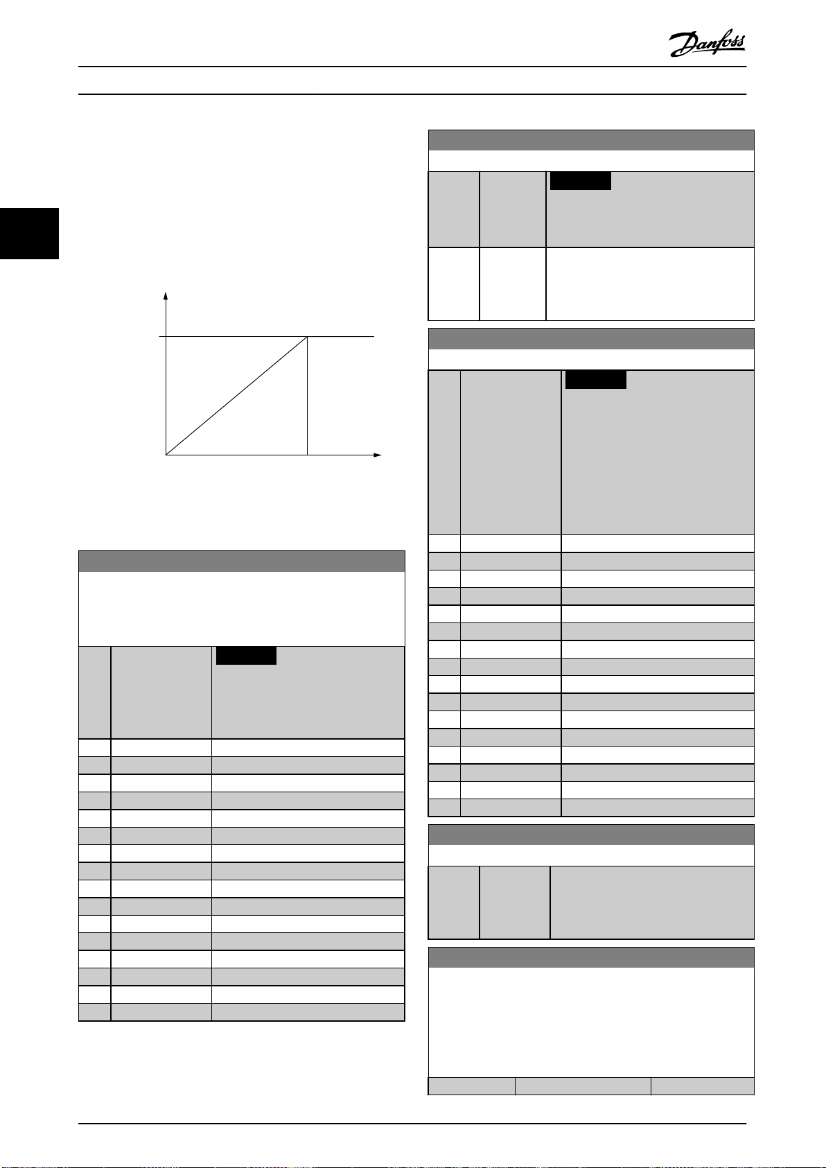
Output value
Output
(Hz)
High output
value
P 5-60(term27)
P 5-63(term29)
High freq.
P 5-62(term27)
P 5-65(term29)
130BA089.11
Parameter Description
VLT® Refrigeration Drive FC 103
33
3.7.6 5-6* Pulse Outputs
Parameters for conguring the scaling and output
functions of pulse outputs. The pulse outputs are
designated to terminals 27 or 29. Select terminal 27 output
in parameter 5-01 Terminal 27 Mode and terminal 29 output
in parameter 5-02 Terminal 29 Mode.
Illustration 3.29 Pulse Output
5-60 Terminal 27 Pulse Output Variable
Select the operation variable assigned for terminal 27 readouts.
This parameter has the same options as parameter group 5-6*
Pulse Output.
Option: Function:
NOTICE
This parameter cannot be
adjusted while the motor is
running.
[0] * No operation
[45] Bus ctrl.
[48] Bus ctrl., timeout
[100] Output frequency
[101] Reference
[102] Feedback
[103] Motor Current
[104] Torque rel to limit
[105] Torq relate to rated
[106] Power
[107] Speed
[108] Torque
[109] Max Out Freq
[113] Ext. Closed Loop 1
[114] Ext. Closed Loop 2
[115] Ext. Closed Loop 3
5-62 Pulse Output Max Freq #27
Range: Function:
NOTICE
This parameter cannot be adjusted
while the motor is running.
5000 Hz* [0 - 32000
Hz]
Set the maximum frequency for terminal
27 corresponding to the output variable
selected in parameter 5-60 Terminal 27
Pulse Output Variable.
5-63 Terminal 29 Pulse Output Variable
Option: Function:
NOTICE
This parameter cannot be
adjusted while the motor is
running.
Select the variable for viewing on
terminal 29. Same options and
functions as parameter group 5-6*
Pulse Output.
[0] * No operation
[45] Bus ctrl.
[48] Bus ctrl., timeout
[100] Output frequency
[101] Reference
[102] Feedback
[103] Motor Current
[104] Torque rel to limit
[105] Torq relate to rated
[106] Power
[107] Speed
[108] Torque
[109] Max Out Freq
[113] Ext. Closed Loop 1
[114] Ext. Closed Loop 2
[115] Ext. Closed Loop 3
5-65 Pulse Output Max Freq #29
Range: Function:
5000 Hz* [0 - 32000
Hz]
5-66 Terminal X30/6 Pulse Output Variable
Select the variable for readout on terminal X30/6.
This parameter is active when VLT® General Purpose I/O MCB 101
is installed in the frequency converter.
Same options and functions as parameter group 5-6* Pulse
Outputs.
Option: Function:
[0] * No operation
Set the maximum frequency for terminal
29 corresponding to the output variable
set in parameter 5-63 Terminal 29 Pulse
Output Variable.
76 Danfoss A/S © 05/2016 All rights reserved. MG16H202
Page 79
Parameter Description Programming Guide
5-66 Terminal X30/6 Pulse Output Variable
Select the variable for readout on terminal X30/6.
This parameter is active when VLT® General Purpose I/O MCB 101
is installed in the frequency converter.
Same options and functions as parameter group 5-6* Pulse
Outputs.
Option: Function:
[45] Bus ctrl.
[48] Bus ctrl., timeout
[100] Output frequency
[101] Reference
[102] Feedback
[103] Motor Current
[104] Torque rel to limit
[105] Torq relate to rated
[106] Power
[107] Speed
[108] Torque
[109] Max Out Freq
[113] Ext. Closed Loop 1
[114] Ext. Closed Loop 2
[115] Ext. Closed Loop 3
5-68 Pulse Output Max Freq #X30/6
Range: Function:
5000
Hz*
[0 32000 Hz]
NOTICE
This parameter cannot be adjusted
while the motor is running.
Select the maximum frequency on terminal
X30/6 referring to the output variable in
parameter 5-66 Terminal X30/6 Pulse Output
Variable.
This parameter is active when VLT® General
Purpose I/O MCB 101 is installed in the
frequency converter.
3.7.8 5-9* Bus-Controlled
This parameter group selects digital and relay outputs via a
eldbus setting.
5-90 Digital & Relay Bus Control
Range: Function:
0* [0 -
2147483647]
This parameter holds the state of the digital
outputs and relays that are controlled by
bus.
A logical 1 indicates that the output is high
or active.
A logical 0 indicates that the output is low
or inactive.
Bit 0 CC digital output, terminal 27
Bit 1 CC digital output, terminal 29
Bit 2 GPIO digital output, terminal X
30/6
Bit 3 GPIO digital output, terminal X
30/7
Bit 4 CC relay 1 output terminal
Bit 5 CC relay 2 output terminal
Bit 6 Option B relay 1 output terminal
Bit 7 Option B relay 2 output terminal
Bit 8 Option B relay 3 output terminal
Bit 9–15Reserved for future terminals
Bit 16 Option C relay 1 output terminal
Bit 17 Option C relay 2 output terminal
Bit 18 Option C relay 3 output terminal
Bit 19 Option C relay 4 output terminal
Bit 20 Option C relay 5 output terminal
Bit 21 Option C relay 6 output terminal
Bit 22 Option C relay 7 output terminal
Bit 23 Option C relay 8 output terminal
Bit 24–31Reserved for future terminals
3 3
3.7.7 5-8* I/O Options
5-80 AHF Cap Reconnect Delay
Range: Function:
25 s* [1 - 120s]Guarantees a minimum o-time for the
capacitors. The timer starts once the AHF
capacitor disconnects and has to expire before
the output is allowed to be on again. It only
turns on again if the frequency converter
power is 20–30%.
MG16H202 Danfoss A/S © 05/2016 All rights reserved. 77
5-93 Pulse Out #27 Bus Control
Range: Function:
0 %* [0 - 100 %] Contains the frequency to apply to the
5-94 Pulse Out #27 Timeout Preset
Range: Function:
0 %* [0 - 100 %] Contains the frequency to apply to the
Table 3.13 Digital Output Bits
digital output terminal 27 when it is
congured as bus-controlled.
digital output terminal 27 when it is
congured as bus-controlled timeout, and
timeout is detected.
Page 80

Parameter Description
VLT® Refrigeration Drive FC 103
5-95 Pulse Out #29 Bus Control
Range: Function:
0 %* [0 - 100 %] Contains the frequency to apply to the
digital output terminal 29 when it is
congured as bus-controlled.
33
5-96 Pulse Out #29 Timeout Preset
Range: Function:
0 %* [0 - 100 %] Contains the frequency to apply to the
digital output terminal 29 when it is
congured as bus-controlled timeout, and
timeout is detected.
5-97 Pulse Out #X30/6 Bus Control
Range: Function:
0 %* [0 - 100 %] Contains the frequency to apply to the
digital output terminal 27 when it is
congured as bus-controlled.
5-98 Pulse Out #X30/6 Timeout Preset
Range: Function:
0 %* [0 - 100 %] Contains the frequency to apply to the
digital output terminal 6 when it is
congured as bus-controlled timeout, and
timeout is detected.
78 Danfoss A/S © 05/2016 All rights reserved. MG16H202
Page 81

Ref./Feedback
[RPM]
Analog input
High Ref./
Feedb. Value'
Low Ref./
Feedb. Value'
'Low Voltage'or
'Low Current'
'High Voltage'or
'High Current'
130BA038.13
1 V 5 V 10 V
300
600
900
1200
1500
[V]
150
Par 6-xx
Par 6-xx
Par 6-xx
Par 6-xx
Parameter Description Programming Guide
3.8 Parameters: 6-** Analog In/Out
3.8.1 6-** Analog In/Out
Parameter group for conguration of the analog input and
output.
3.8.2 6-0* Analog I/O Mode
Parameter group for setting up the analog I/O congu-
ration.
The frequency converter is equipped with 2 analog inputs:
Terminals 53
•
Terminals 54
•
The analog inputs can be allocated freely to either voltage
(0–10 V) or current input (0/4–20 mA).
NOTICE
Thermistors may be connected to either an analog or a
digital input.
6-00 Live Zero Timeout Time
Range: Function:
10s* [1 -
Enter the live zero timeout in s. Live zero timeout
99 s]
time is active for analog inputs, that is, terminal 53
or terminal 54, used as reference or feedback
sources.
If the reference signal value associated with the
selected current input drops below 50% of the
value set in:
Parameter 6-10 Terminal 53 Low Voltage.
•
Parameter 6-12 Terminal 53 Low Current.
•
Parameter 6-20 Terminal 54 Low Voltage.
•
Parameter 6-22 Terminal 54 Low Current.
•
For a time period longer than the time set in
parameter 6-00 Live Zero Timeout Time, the function
selected in parameter 6-01 Live Zero Timeout
Function is activated.
6-01 Live Zero Timeout Function
Option: Function:
Parameter 6-22 Terminal 54 Low
•
Current.
The function can also be activated for a time
period dened in parameter 6-00 Live Zero
Timeout Time. If several timeouts occur
simultaneously, the frequency converter
prioritizes the timeout functions as follows:
1. Parameter 6-01 Live Zero Timeout
Function.
2. Parameter 8-04 Control Timeout
Function.
[0] * O
[1] Freeze
output
[2] Stop Overruled to stop.
[3] Jogging Overruled to jog speed.
[4] Max. speed Overruled to maximum speed.
[5] Stop and
trip
[21] Min.
Reference
[22] Max.
Reference
Frozen at the present value. Live zero timeout
time does not apply to freeze output.
Overruled to stop with subsequent trip.
3 3
6-01 Live Zero Timeout Function
Option: Function:
MG16H202 Danfoss A/S © 05/2016 All rights reserved. 79
Select the timeout function. The function set
in parameter 6-01 Live Zero Timeout Function is
activated if the input signal on terminal 53 or
54 is below 50% of the value in:
Parameter 6-10 Terminal 53 Low
•
Voltage.
Parameter 6-12 Terminal 53 Low
•
Current.
Parameter 6-20 Terminal 54 Low
•
Voltage.
Illustration 3.30 Live Zero Conditions
Page 82

Parameter Description
VLT® Refrigeration Drive FC 103
3.8.3 6-1* Analog Input 1
6-15 Terminal 53 High Ref./Feedb. Value
Range: Function:
Parameters for conguring the scaling and limits for analog
input 1 (terminal 53).
33
6-10 Terminal 53 Low Voltage
voltage/high current value set in
parameter 6-11 Terminal 53 High
Voltage and parameter 6-13 Terminal
53 High Current.
Range: Function:
0.07 V* [ 0 par. 6-11
V]
NOTICE
For the live zero alarms to work,
parameter 6-10 Terminal 53 Low Voltage
must have a value of 1 V or greater.
6-16 Terminal 53 Filter Time Constant
Range: Function:
0.001 s* [0.001 - 10
s]
NOTICE
This parameter cannot be adjusted
while the motor is running.
Enter the low voltage value. This analog input
scaling value should correspond to the low
reference feedback value set in
parameter 6-14 Terminal 53 Low Ref./Feedb.
Value.
6-11 Terminal 53 High Voltage
Enter the lter time constant. This
constant is a
lter time for suppressing electrical noise
in terminal 53. A high value improves
dampening, but also increases the delay
through the lter.
rst-order digital low-pass
Range: Function:
10 V* [ par. 6-10
- 10 V]
Enter the high voltage value. This analog
input scaling value should correspond to the
high reference feedback value set in
parameter 6-15 Terminal 53 High Ref./Feedb.
Value.
6-12 Terminal 53 Low Current
Range: Function:
4 mA* [ 0 -
par. 6-13
mA]
Enter the low current value. This reference
signal should correspond to the low reference
feedback value, set in parameter 6-14 Terminal
53 Low Ref./Feedb. Value. Set the value at >2
mA to activate the live zero timeout function
in parameter 6-01 Live Zero Timeout Function.
6-13 Terminal 53 High Current
Range: Function:
20 mA* [ par. 6-12 -
20 mA]
Enter the high current value
corresponding to the high reference/
feedback set in parameter 6-15 Terminal 53
High Ref./Feedb. Value.
6-14 Terminal 53 Low Ref./Feedb. Value
Range: Function:
0* [-999999.999 -
999999.999]
Enter the analog input scaling value that
corresponds to the low voltage/low
current set in parameter 6-10 Terminal 53
Low Voltage and parameter 6-12 Terminal
53 Low Current.
6-15 Terminal 53 High Ref./Feedb. Value
Range: Function:
Size
related*
[-999999.999 -
999999.999]
Enter the analog input scaling
value that corresponds to the high
6-17 Terminal 53 Live Zero
Option: Function:
Disables the live zero monitoring, for example if
the analog outputs are used as part of a
decentral I/O system (that is if these are used to
feed a building management system with data,
and not as part of any control functions related
to the frequency converter).
[0] Disabled
[1] * Enabled
3.8.4 6-2* Analog Input 2
Parameters for conguring the scaling and limits for analog
input 2 (terminal 54).
6-20 Terminal 54 Low Voltage
Range: Function:
0.07 V* [ 0 - par.
6-21 V]
6-21 Terminal 54 High Voltage
Range: Function:
10 V* [ par. 6-20
- 10 V]
Enter the low voltage value. This analog
input scaling value should correspond to
the low reference feedback value set in
parameter 6-24 Terminal 54 Low Ref./Feedb.
Value.
Enter the high voltage value. This analog
input scaling value should correspond to the
high reference feedback value set in
parameter 6-25 Terminal 54 High Ref./Feedb.
Value.
80 Danfoss A/S © 05/2016 All rights reserved. MG16H202
Page 83

Parameter Description Programming Guide
6-22 Terminal 54 Low Current
Range: Function:
4 mA* [ 0 -
par. 6-23
mA]
Enter the low current value. This reference
signal should correspond to the low reference
feedback value, set in parameter 6-24 Terminal
54 Low Ref./Feedb. Value. Set the value at >2
mA to activate the live zero timeout function
in parameter 6-01 Live Zero Timeout Function.
6-23 Terminal 54 High Current
Range: Function:
20 mA* [ par. 6-22
- 20 mA]
Enter the high current value
corresponding to the high reference
feedback value set in
parameter 6-25 Terminal 54 High Ref./Feedb.
Value.
6-24 Terminal 54 Low Ref./Feedb. Value
Range: Function:
-1* [-999999.999 -
999999.999]
Enter the analog input scaling value that
corresponds to the low voltage/low
current value set in
parameter 6-20 Terminal 54 Low Voltage
and parameter 6-22 Terminal 54 Low
Current.
6-25 Terminal 54 High Ref./Feedb. Value
Range: Function:
Size
related*
[-999999.999 -
999999.999]
Enter the analog input scaling
value that corresponds to the high
voltage/high current value set in
parameter 6-21 Terminal 54 High
Voltage and parameter 6-23 Terminal
54 High Current.
6-27 Terminal 54 Live Zero
Option: Function:
and not as part of any control functions related
to the frequency converter).
[0] Disabled
[1] * Enabled
3.8.5 6-3* Analog Input 3 General Purpose
I/O MCB 101
Parameter group for conguring the scale and limits for
analog input 3 (X30/11) in VLT® General Purpose I/OMCB
101.
6-30 Terminal X30/11 Low Voltage
Range: Function:
0.07 V* [ 0 - par.
6-31 V]
6-31 Terminal X30/11 High Voltage
Range: Function:
10 V* [ par. 6-30 -
10 V]
6-34 Term. X30/11 Low Ref./Feedb. Value
Range: Function:
0* [-999999.999 -
999999.999]
Sets the analog input scaling value to
correspond to the low reference feedback
value (set in parameter 6-34 Term. X30/11
Low Ref./Feedb. Value).
Sets the analog input scaling value to
correspond to the high reference feedback
value (set in parameter 6-35 Term. X30/11
High Ref./Feedb. Value).
Sets the analog input scaling value to
correspond to the low voltage value (set
in parameter 6-30 Terminal X30/11 Low
Voltage).
3 3
6-26 Terminal 54 Filter Time Constant
Range: Function:
0.001 s* [0.001 - 10
s]
NOTICE
This parameter cannot be adjusted
while the motor is running.
Enter the lter time constant. This is a
rst-order digital low-pass lter time
constant for suppressing electrical noise in
terminal 54. Increasing the value improves
dampening but also increases the time
delay through the lter.
6-35 Term. X30/11 High Ref./Feedb. Value
Range: Function:
100* [-999999.999 -
999999.999]
Sets the analog input scaling value to
correspond to the high-voltage value
(set in parameter 6-31 Terminal X30/11
High Voltage).
6-36 Term. X30/11 Filter Time Constant
Range: Function:
0.001 s* [0.001 - 10
s]
NOTICE
This parameter cannot be adjusted
while the motor is running.
6-27 Terminal 54 Live Zero
Option: Function:
Disables the live zero-monitoring, for example if
the analog outputs are used as part of a
decentral I/O system (that is if these are used to
feed a building management system with data,
MG16H202 Danfoss A/S © 05/2016 All rights reserved. 81
Enter the lter time constant. This
constant is a
lter time for suppressing electrical noise
in terminal X30/11. A high value improves
dampening, but also increases the delay
through the lter.
rst-order digital low-pass
Page 84

Parameter Description
VLT® Refrigeration Drive FC 103
6-37 Term. X30/11 Live Zero
Option: Function:
This parameter makes it possible to disable the
live zero-monitoring. For example, to be used if
the analog outputs are used in a decentral I/O
33
[0] Disabled
[1] * Enabled
system (when an analog output does not full
any control function, but feeds a data storage
device).
3.8.6 6-4* Analog Input X30/12
Parameter group for conguring the scale and limits for
analog input 4 (X30/12) placed on VLT® General Purpose
I/O MCB 101.
6-40 Terminal X30/12 Low Voltage
Range: Function:
0.07 V* [ 0 - par.
6-41 V]
6-41 Terminal X30/12 High Voltage
Range: Function:
10 V* [ par. 6-40 -
10 V]
Sets the analog input scaling value to
correspond to the low reference feedback
value set in parameter 6-44 Term. X30/12
Low Ref./Feedb. Value.
Sets the analog input scaling value to
correspond to the high reference feedback
value set in parameter 6-45 Term. X30/12
High Ref./Feedb. Value.
6-46 Term. X30/12 Filter Time Constant
Range: Function:
in terminal X30/12. A high value improves
dampening, but also increases the delay
through the lter.
6-47 Term. X30/12 Live Zero
Option: Function:
This parameter makes it possible to disable the
live zero-monitoring. For example, to be used if
the analog outputs are used in a decentral I/O
system (when an analog output does not full
any control function, but feeds a data storage
device).
[0] Disabled
[1] * Enabled
3.8.7 6-5* Analog Output 1
Parameters for conguring the scaling and limits for analog
output 1, that is terminal 42. Analog outputs are current
outputs: 0/4–20 mA. Common terminal (terminal 39) is the
same terminal and has the same electrical potential for
analog common and digital common connection.
Resolution on analog output is 12 bit.
6-50 Terminal 42 Output
Option: Function:
NOTICE
Values for setting the minimum
reference in open loop are in
6-44 Term. X30/12 Low Ref./Feedb. Value
Range: Function:
0* [-999999.999 -
999999.999]
Sets the analog output scaling value to
correspond to the low voltage value set
in parameter 6-40 Terminal X30/12 Low
Voltage.
6-45 Term. X30/12 High Ref./Feedb. Value
Range: Function:
100* [-999999.999 -
999999.999]
Sets the analog input scaling value to
correspond to the high voltage value
set in parameter 6-41 Terminal X30/12
High Voltage.
6-46 Term. X30/12 Filter Time Constant
Range: Function:
0.001 s* [0.001 - 10
s]
NOTICE
This parameter cannot be adjusted
while the motor is running.
Enter the lter time constant. This
constant is a
lter time for suppressing electrical noise
rst-order digital low-pass
[0] No operation
[100]*Output
frequency
[101] Reference Minimum reference–Maximum reference,
[102] Feedback
[103] Motor Current 0–Inverter maximum current
parameter 3-02 Minimum Reference.
Values for the maximum reference
for open loop are in
parameter 3-03 Maximum
Reference.
This parameter enables the function of
terminal 42 as an analog current output.
Depending on the option selected, the
output is either 0–20 mA or 4–20 mA.
The current value can be read out in the
LCP in parameter 16-65 Analog Output 42
[mA].
0–100 Hz, (0–20 mA).
(0–20 mA).
(parameter 16-37 Inv. Max. Current), (0-20
mA).
82 Danfoss A/S © 05/2016 All rights reserved. MG16H202
Page 85

130BA075.13
(mA)
0%
20
0/4
100%
Current
Analogue
output
Min Scale
par. 6-51
Variable
for
output
example:
Speed (RPM)
Analogue
Output
Max Scale
par. 6-52
Parameter Description Programming Guide
6-50 Terminal 42 Output
Option: Function:
[104] Torque rel to
limit
[105] Torq relate to
rated
[106] Power 0–Motor rated power, (0–20 mA).
0–Torque limit (parameter 4-16 Torque
Limit Motor Mode), (0–20 mA).
0–Motor rated torque, (0–20 mA).
6-50 Terminal 42 Output
Option: Function:
[145] Ext. CL 3
4-20mA
[150] Max Out Fr
4-20 mA
[184] Mirror AI53 mA
0–100%.
3 3
[185] Mirror AI54 mA
[107] Speed 0–Speed high limit
6-51 Terminal 42 Output Min Scale
Range: Function:
0 %* [0 -
200 %]
Scale for the minimum output (0 mA or 4 mA)
of the analog signal at terminal 42.
Set the value to be the percentage of the full
range of the variable selected in
parameter 6-50 Terminal 42 Output.
6-52 Terminal 42 Output Max Scale
Range: Function:
100%* [0 -
Scale for the maximum output (20 mA) of the
200
analog signal at terminal 42.
%]
Set the value to be the percentage of the full
range of the variable selected in
parameter 6-50 Terminal 42 Output.
[108] Torque
[109] Max Out Freq
[113] Ext. Closed
Loop 1
[114] Ext. Closed
Loop 2
[115] Ext. Closed
Loop 3
[121] Air pres. to
Flow
[122] Air pres. to
Flow 4-20mA
[130] Output freq.
(parameter 4-13 Motor Speed High Limit
[RPM] and parameter 4-14 Motor Speed
High Limit [Hz]), (0–20 mA).
0–100%, (0–20 mA).
0–100%, (0–20 mA).
0–100%, (0–20 mA).
0–100 Hz.
4-20mA
[131] Reference
Minimum reference–Maximum reference.
4-20mA
[132] Feedback
4-20mA
-200% to +200% of
parameter 20-14 Maximum Reference/
Feedb.
[133] Motor cur.
4-20mA
0–Inverter maximum current
(parameter 16-37 Inv. Max. Current).
Illustration 3.31 Output Current vs Reference
Variable
[134] Torq.% lim 4-20mA0–Torque limit (parameter 4-16 Torque
Limit Motor Mode).
[135] Torq.% nom
0–Motor rated torque.
4-20mA
[136] Power 4-20mA 0–Motor rated power.
[137] Speed 4-20mA 0–Speed high limit
(parameter 4-13 Motor Speed High Limit
[RPM] and parameter 4-14 Motor Speed
High Limit [Hz]).
[138] Torque 4-20mA
[139] Bus ctrl. 0–100%, (0–20 mA).
Example 1:
Variable value = output frequency, range = 0–100 Hz.
Range needed for output = 0–50 Hz.
Output signal 0 mA or 4 mA is needed at 0 Hz (0% of
It is possible to obtain a value lower than 20 mA
at full scale by programming values >100% by
using a formula as follows:
20mA/desired maximumcurrent × 100 %
20mA
i . e. 10mA :
10mA
× 100 % = 200 %
range). Set parameter 6-51 Terminal 42 Output Min Scale to
[140] Bus ctrl. 4-20mA0–100%.
0%.
Output signal 20 mA is needed at 50 Hz (50% of range).
[141] Bus ctrl t.o. 0–100%, (0–20 mA).
[142] Bus ctrl t.o.
0–100%.
4-20mA
[143] Ext. CL 1
0–100%.
4-20mA
[144] Ext. CL 2
4-20mA
0–100%.
Set parameter 6-52 Terminal 42 Output Max Scale to 50%.
MG16H202 Danfoss A/S © 05/2016 All rights reserved. 83
Page 86

0/4 mA
20 mA
50% 100%0%
50Hz 100Hz0Hz
130BA858.10
0/4 mA
20 mA
50% 75% 100%0%
0% +100% +200%-200%
130BA856.10
20 mA
10 mA
0/4 mA
100% 200%
0%
Max ref Max ref X 20/10Min ref
130BA857.10
Parameter Description
VLT® Refrigeration Drive FC 103
33
Illustration 3.32 Example 1
Example 2:
Variable = feedback, range = -200% to +200%.
Range needed for output = 0–100%.
Output signal 0 mA or 4 mA is needed at 0% (50% of
range). Set parameter 6-51 Terminal 42 Output Min Scale to
50%.
Output signal 20 mA is needed at 100% (75% of range).
Set parameter 6-52 Terminal 42 Output Max Scale to 75%.
Illustration 3.33 Example 2
Example 3:
Variable value = reference, range = minimum reference–
maximum reference
Range needed for output = minimum reference (0%)–
maximum reference (100%), 0–10 mA.
Output signal 0 mA or 4 mA is needed at minimum
reference. Set parameter 6-51 Terminal 42 Output Min Scale
to 0%.
Output signal 10 mA is needed at maximum reference
(100% of range). Set parameter 6-52 Terminal 42 Output
Max Scale to 200%.
(20 mA/10 mA x 100%=200%).
Illustration 3.34 Example 3
6-53 Terminal 42 Output Bus Control
Range: Function:
0 %* [0 - 100 %] Holds the level of output 42 if controlled by
bus.
6-54 Terminal 42 Output Timeout Preset
Range: Function:
0 %* [0 -
100 %]
Holds the preset level of output 42.
If a timeout function is selected in
parameter 6-50 Terminal 42 Output, the output
is preset to this level if a eldbus timeout
occurs.
3.8.8 6-6* Analog Output 2 MCB 101
Analog outputs are current outputs: 0/4–20 mA. Common
terminal (terminal X30/8) is the same terminal and
electrical potential for analog common connection.
Resolution on analog output is 12 bit.
6-60 Terminal X30/8 Output
Same options and functions as parameter 6-50 Terminal 42
Output.
6-61 Terminal X30/8 Min. Scale
Range: Function:
0 %* [0 -
200 %]
Scales the minimum output of the selected analog
signal on terminal X30/8. Scale the minimum value
as a percentage of the maximum signal value, that
is 0 mA (or 0 Hz) is required at 25% of the
maximum output value and 25% is programmed.
The value can never exceed the corresponding
setting in parameter 6-62 Terminal X30/8 Max. Scale
if the value is below 100%.
This parameter is active when VLT® General
Purpose I/O MCB 101 is mounted in the frequency
converter.
84 Danfoss A/S © 05/2016 All rights reserved. MG16H202
Page 87

Parameter Description Programming Guide
6-62 Terminal X30/8 Max. Scale
Range: Function:
100%* [0 -
200 %
]
Scales the maximum output of the selected
analog signal on terminal X30/8. Scale the value
to the required maximum value of the current
signal output. Scale the output to give a lower
current than 20 mA at full scale, or 20 mA at an
output below 100% of the maximum signal value.
If 20 mA is the required output current at a value
between 0–100% of the full-scale output,
program the percentage value in the parameter,
that is 50%=20 mA. If a current 4–20 mA is
required at maximum output (100%), calculate
the percentage value as follows:
20mA/desired maximumcurrent × 100 %
20mA
i . e. 10mA :
× 100 % = 200 %
10mA
6-63 Terminal X30/8 Output Bus Control
Range: Function:
0 %* [0 - 100 %] Contains the value to apply to the output
terminal when it is congured as buscontrolled.
6-64 Terminal X30/8 Output Timeout Preset
Range: Function:
0 %* [0 - 100 %] Contains the value to apply to the output
terminal, when it is congured as buscontrolled timeout and timeout is detected.
6-70 Terminal X45/1 Output
Select the output of terminal X45/1 of VLT® Extended Relay Card
MCB 113.
Option: Function:
[0] * No operation
[100] Output frequency
[101] Reference
[102] Feedback
[103] Motor Current
[104] Torque rel to limit
[105] Torq relate to rated
[106] Power
[107] Speed
[108] Torque
[109] Max Out Freq
[113] Ext. Closed Loop 1
[114] Ext. Closed Loop 2
[115] Ext. Closed Loop 3
[121] Air pres. to Flow
[122] Air pres. to Flow 4-20mA
[130] Output freq. 4-20mA
[131] Reference 4-20mA
[132] Feedback 4-20mA
[133] Motor cur. 4-20mA
[134] Torq.% lim 4-20 mA
6-70 Terminal X45/1 Output
Select the output of terminal X45/1 of VLT® Extended Relay Card
MCB 113.
Option: Function:
[135] Torq.% nom 4-20mA
[136] Power 4-20mA
[137] Speed 4-20mA
[138] Torque 4-20mA
[139] Bus ctrl.
[140] Bus ctrl. 4-20 mA
[141] Bus ctrl t.o.
[142] Bus ctrl t.o. 4-20mA
[143] Ext. CL 1 4-20mA
[144] Ext. CL 2 4-20mA
[145] Ext. CL 3 4-20mA
[150] Max Out Fr 4-20 mA
[184] Mirror AI53 mA
[185] Mirror AI54 mA
6-71 Terminal X45/1 Min. Scale
Enter the minimum scaling value of output of the analog signal
on terminal X45/1.
Range: Function:
0 %* [0 - 200 %]
6-72 Terminal X45/1 Max. Scale
Enter the maximum scaling value of output of the analog signal
on terminal X45/1.
Range: Function:
100 %* [0 - 200 %]
6-73 Terminal X45/1 Bus Control
Enter the output value for terminal X45/1 when the eldbus
controls the terminal.
Range: Function:
0 %* [0 - 100 %]
6-74 Terminal X45/1 Output Timeout Preset
Enter the output value for terminal X45/1 when the bus control
timeout for the terminal is detected.
Range: Function:
0 %* [0 - 100 %]
6-80 Terminal X45/3 Output
Select the output of terminal X45/3 of VLT® Extended Relay Card
MCB 113.
Option: Function:
[0] * No operation
[100] Output frequency
[101] Reference
[102] Feedback
[103] Motor Current
[104] Torque rel to limit
[105] Torq relate to rated
3 3
MG16H202 Danfoss A/S © 05/2016 All rights reserved. 85
Page 88

Parameter Description
VLT® Refrigeration Drive FC 103
6-80 Terminal X45/3 Output
Select the output of terminal X45/3 of VLT® Extended Relay Card
MCB 113.
Option: Function:
[106] Power
33
[107] Speed
[108] Torque
[109] Max Out Freq
[113] Ext. Closed Loop 1
[114] Ext. Closed Loop 2
[115] Ext. Closed Loop 3
[121] Air pres. to Flow
[122] Air pres. to Flow 4-20mA
[130] Output freq. 4-20mA
[131] Reference 4-20mA
[132] Feedback 4-20mA
[133] Motor cur. 4-20mA
[134] Torq.% lim 4-20 mA
[135] Torq.% nom 4-20mA
[136] Power 4-20mA
[137] Speed 4-20mA
[138] Torque 4-20mA
[139] Bus ctrl.
[140] Bus ctrl. 4-20 mA
[141] Bus ctrl t.o.
[142] Bus ctrl t.o. 4-20mA
[143] Ext. CL 1 4-20mA
[144] Ext. CL 2 4-20mA
[145] Ext. CL 3 4-20mA
[150] Max Out Fr 4-20 mA
[184] Mirror AI53 mA
[185] Mirror AI54 mA
6-84 Terminal X45/3 Output Timeout Preset
Enter the output value for terminal X45/3 when the bus control
timeout for the terminal is detected.
Range: Function:
0 %* [0 - 100 %]
6-81 Terminal X45/3 Min. Scale
Enter the minimum scaling value of output of the analog signal
on terminal X45/3.
Range: Function:
0 %* [0 - 200 %]
6-82 Terminal X45/3 Max. Scale
Enter the maximum scaling value of output of the analog signal
on terminal X45/3.
Range: Function:
100 %* [0 - 200 %]
6-83 Terminal X45/3 Bus Control
Enter the output value for terminal X45/3 when the eldbus
controls the terminal.
Range: Function:
0 %* [0 - 100 %]
86 Danfoss A/S © 05/2016 All rights reserved. MG16H202
Page 89

Parameter Description Programming Guide
3.9 Parameters: 8-** Communications and
Options
3.9.1 8-** Comm. and Options
3.9.2 8-0* General Settings
8-01 Control Site
Option: Function:
The setting in this parameter overrides
the settings in parameter 8-50 Coasting
Select to parameter 8-56 Preset Reference
Select.
[0] * Digital and
ctrl.word
[1] Digital only Use digital inputs only.
[2] Controlword
only
Use both digital input and control word.
Use control word only.
8-02 Control Source
Option: Function:
NOTICE
This parameter cannot be adjusted
while the motor is running.
Select the source of the control word: 1 of 2
serial interfaces, or 4 installed options. During
initial power-up, the frequency converter
automatically sets this parameter to [3] Option
A if it detects a valid
in slot A. If the option is removed, the
frequency converter detects a change in the
conguration, sets parameter 8-02 Control
Source back to default setting [1] FC Port, and
the frequency converter then trips. If an
option is installed after initial power-up, the
setting of parameter 8-02 Control Source does
not change but the frequency converter trips
and displays alarm 67, Option Changed.
[0] None
[1] FC Port
[2] USB Port
[3] Option A
[4] Option B
[5] Option C0
[6] Option C1
[30] External Can
8-03 Control Timeout Time
Range: Function:
Size
related*
[0.5 18000 s]
Enter the maximum time expected to pass
between the reception of 2 consecutive
telegrams. If this time is exceeded, it
indicates that the serial communication has
eldbus option installed
8-03 Control Timeout Time
Range: Function:
stopped. The function selected in
parameter 8-04 Control Timeout Function is
then carried out.
The object list holds information on the
objects that triggers the control timeout:
Analog outputs
•
Binary outputs
•
AV0
•
AV1
•
AV2
•
AV4
•
BV1
•
BV2
•
BV3
•
BV4
•
BV5
•
Multistate outputs
•
8-04 Control Timeout Function
Option: Function:
Select the timeout function. The
timeout function is activated when
the control word fails to be updated
within the time period specied in
parameter 8-03 Control Timeout Time.
[20] N2 Override Release only appears
after setting the Metasys N2 protocol.
[0] * O
[1] Freeze output
[2] Stop
[3] Jogging
[4] Max. speed
[5] Stop and trip
[7] Select setup 1
[8] Select setup 2
[9] Select setup 3
[10] Select setup 4
[20] N2 Override
Release
[21] Min. Reference
[22] Max. Reference
8-05 End-of-Timeout Function
Option: Function:
Select the action after receiving a valid control
word following a timeout.
This parameter is active only when
parameter 8-04 Control Timeout Function is set
to:
3 3
MG16H202 Danfoss A/S © 05/2016 All rights reserved. 87
Page 90
Parameter Description
VLT® Refrigeration Drive FC 103
8-05 End-of-Timeout Function
Option: Function:
[7] Set-up 1.
•
[8] Set-up 2.
•
[9] Set-up 3.
33
[0] Hold set-upRetains the set-up selected in
[1] * Resume
set-up
•
[10] Set-up 4.
•
parameter 8-04 Control Timeout Function and
shows a warning until parameter 8-06 Reset
Control Timeout toggles. Then the frequency
converter resumes its original set-up.
Resumes the set-up that was active before the
timeout.
8-06 Reset Control Timeout
Option: Function:
This parameter is active only when option [0] Hold
set-up has been selected in parameter 8-05 End-ofTimeout Function.
[0] * Do not
reset
[1] Do
reset
Retains the set-up specied in
parameter 8-04 Control Timeout Function:
[7] Set-up 1.
•
[8] Set-up 2.
•
[9] Set-up 3.
•
[10] Set-up 4.
•
Returns the frequency converter to the original
set-up following a control word timeout. When the
value is set to [1] Do reset, the frequency converter
performs the reset and immediately reverts to the
[0] Do not reset setting.
8-10 Control Prole
Option: Function:
installed eldbus. Only the selections valid
for the eldbus installed in slot A are
visible in the LPC display.
[0] * FC prole
[1] PROFIdrive
prole
[5] ODVA
[7] CANopen DSP
402
Available only with VLT® DeviceNet MCA
104 and VLT® EtherNet IP MCA 121.
8-13 Congurable Status Word STW
Array [16]
Option: Function:
This parameter enables conguration of bits
12–15 in the status word.
[0] No function
[1] * Prole
Default
[2] Alarm 68
Only
[3] Trip excl
Alarm 68
[16] T37 DI status The bit indicates the status of terminal 37.
The function corresponds to the prole
default selected in parameter 8-10 Control
Prole.
Only set if alarm 68, Safe Torque O occurs.
Set if a trip occurs, except if alarm 68, Safe
Torque O executes the trip.
0 indicates that T37 is low (Safe Torque O).
1 indicates that T37 is high (normal).
Activate or deactivate the storing of data in non-volatile
memory.
8-07 Diagnosis Trigger
Option: Function:
To send no extended diagnosis data (EDD),
select [0] Disable. To send EDD upon alarms,
select [1] Trigger on alarms. To send EDD
upon alarms or warnings, select [2] Trigger
alarm/warn. Not all eldbusses support the
diagnosis functions.
[0] * Disable
[1] Trigger on
alarms
[2] Trigger
alarm/warn.
3.9.3 8-1* Ctrl. Word Settings
8-10 Control Prole
Option: Function:
Select the interpretation of the control
and status words corresponding to the
8-16 Store Data Values
Option: Function:
[0] * O
[1] Store all setups
[2] Store all setups
3.9.4 8-3* FC Port Settings
8-30 Protocol
Protocol selection for the integrated FC (standard) port (RS485)
on the control card.
Option: Function:
[0]*FC Communication according to the FC Protocol as
described in the VLT® Refrigeration Drive FC 103
Design Guide, chapter RS485 Installation and Setup.
[1] FC MC Same as [0] FC but to be used when
downloading SW to the frequency converter or
uploading dll le (covering information
88 Danfoss A/S © 05/2016 All rights reserved. MG16H202
Page 91

Parameter Description Programming Guide
8-30 Protocol
Protocol selection for the integrated FC (standard) port (RS485)
on the control card.
Option: Function:
regarding parameters available in the frequency
converter and their inter-dependencies) to MCT
10 Set-up Software.
[2] Modbus
RTU
[3] MetasysN2Communication protocol. The N2 software
[9] FC
option
Communication according to the Modbus RTU
protocol as described in the VLT® Refrigeration
Drive FC 103 Design Guide, chapter RS485 Installation and Set-up.
protocol is designed to be general in nature in
order to accommodate the unique properties
each device may have. See VLT® HVAC Drive FC
102 Metasys Operating Instructions.
To be used when a gateway is connected to the
integrated RS485 port.
Following changes take place:
Address for the FC port is set to 1 and
•
parameter 8-31 Address is now used to
set the address for the gateway on the
network.
Baud rate for the FC port is set to a
•
xed value (115.200 Baud), and
parameter 8-32 Baud Rate is now used
to set the baud rate for the network
port on the gateway.
NOTICE
Further details can be found in VLT® HVAC Drive FC 102
Metasys Operating Instructions.
8-31 Address
Range: Function:
Size related* [ 1 - 255] Enter the address for the frequency
converter (standard) port.
Valid range: 1–126.
8-33 Parity / Stop Bits
Option: Function:
Parity and stop bits for the protocol
parameter 8-30 Protocol using the FC
port. For some of the protocols, not all
options are visible. Default depends on
the protocol selected.
[0] Even Parity, 1 Stop
Bit
[1] Odd Parity, 1 Stop
Bit
[2] No Parity, 1 Stop
Bit
[3] No Parity, 2 Stop
Bits
8-35 Minimum Response Delay
Range: Function:
10 ms* [ 5 - 10000
ms]
Specify the minimum delay time
between receiving a request and
transmitting a response. This is used for
overcoming modem turnaround delays.
8-36 Maximum Response Delay
Range: Function:
Size
related*
[ 11 - 10001
ms]
Specify the maximum allowed delay
time between transmitting a request
and receiving a response. Exceeding
this delay time causes control word
timeout.
8-37 Maximum Inter-Char Delay
Range: Function:
Size related* [ 0.00 -
35.00 ms]
Specify the maximum allowed time
interval between receipt of 2 bytes.
This parameter activates timeout if
transmission is interrupted.
3 3
8-32 Baud Rate
Option: Function:
Baud rates 9600, 19200, 38400, and 76800 are
valid for BACnet only.
The default value depends on the FC protocol.
[0] 2400 Baud
[1] 4800 Baud
[2] 9600 Baud
[3] 19200 Baud
[4] 38400 Baud
[5] 57600 Baud
[6] 76800 Baud
[7] 115200 Baud
MG16H202 Danfoss A/S © 05/2016 All rights reserved. 89
Page 92

Parameter Description
VLT® Refrigeration Drive FC 103
3.9.5 8-4* Telegram Selection
8-42 PCD Write Conguration
Range: Function:
8-40 Telegram Selection
Option: Function:
Enables use of freely congurable
33
[1] * Standard telegram 1
[100] None
[101] PPO 1
[102] PPO 2
[103] PPO 3
[104] PPO 4
[105] PPO 5
[106] PPO 6
[107] PPO 7
[108] PPO 8
[200] Custom telegram 1
telegrams or standard telegrams for
the FC port.
8-42 PCD Write Conguration
Range: Function:
[0] None
[302] Minimum Reference
[303] Maximum Reference
[341] Ramp 1 Ramp Up Time
[342] Ramp 1 Ramp Down Time
[351] Ramp 2 Ramp Up Time
[352] Ramp 2 Ramp Down Time
[380] Jog Ramp Time
[381] Quick Stop Ramp Time
[411] Motor Speed Low Limit [RPM]
[412] Motor Speed Low Limit [Hz]
[413] Motor Speed High Limit [RPM]
[414] Motor Speed High Limit [Hz]
[416] Torque Limit Motor Mode
[417] Torque Limit Generator Mode
[553] Term. 29 High Ref./Feedb. Value
[558] Term. 33 High Ref./Feedb. Value
[590] Digital & Relay Bus Control
[593] Pulse Out #27 Bus Control
[595] Pulse Out #29 Bus Control
[597] Pulse Out #X30/6 Bus Control
[615] Terminal 53 High Ref./Feedb. Value
[625] Terminal 54 High Ref./Feedb. Value
[653] Terminal 42 Output Bus Control
[663] Terminal X30/8 Output Bus Control
[673] Terminal X45/1 Bus Control
[683] Terminal X45/3 Bus Control
[890] Bus Jog 1 Speed
[891] Bus Jog 2 Speed
[894] Bus Feedback 1
[895] Bus Feedback 2
[896] Bus Feedback 3
[1680] Fieldbus CTW 1
[1682] Fieldbus REF 1
[1685] FC Port CTW 1
[1686] FC Port REF 1
[2021] Setpoint 1
[2022] Setpoint 2
[2023] Setpoint 3
[2643] Terminal X42/7 Bus Control
[2653] Terminal X42/9 Bus Control
[2663] Terminal X42/11 Bus Control
8-43 PCD Read Conguration
Range: Function:
[0] None
[894] Bus Feedback 1
[895] Bus Feedback 2
[896] Bus Feedback 3
[1397] Alert Alarm Word
[1398] Alert Warning Word
[1399] Alert Status Word
[1500] Operating hours
[1501] Running Hours
[1502] kWh Counter
[1600] Control Word
[1601] Reference [Unit]
[1602] Reference [%]
[1603] Status Word
[1605] Main Actual Value [%]
[1609] Custom Readout
[1610] Power [kW]
[1611] Power [hp]
[1612] Motor Voltage
[1613] Frequency
[1614] Motor current
[1615] Frequency [%]
[1616] Torque [Nm]
[1617] Speed [RPM]
[1618] Motor Thermal
[1622] Torque [%]
[1624] Calibrated Stator Resistance
[1630] DC Link Voltage
[1632] Brake Energy /s
[1633] Brake Energy /2 min
[1634] Heatsink Temp.
[1635] Inverter Thermal
[1638] SL Controller State
[1639] Control Card Temp.
[1650] External Reference
[1652] Feedback[Unit]
[1653] Digi Pot Reference
[1654] Feedback 1 [Unit]
[1655] Feedback 2 [Unit]
[1656] Feedback 3 [Unit]
90 Danfoss A/S © 05/2016 All rights reserved. MG16H202
Page 93
Parameter Description Programming Guide
8-43 PCD Read Conguration
Range: Function:
[1660] Digital Input
[1661] Terminal 53 Switch Setting
[1662] Analog Input 53
[1663] Terminal 54 Switch Setting
[1664] Analog Input 54
[1665] Analog Output 42 [mA]
[1666] Digital Output [bin]
[1667] Pulse Input #29 [Hz]
[1668] Pulse Input #33 [Hz]
[1669] Pulse Output #27 [Hz]
[1670] Pulse Output #29 [Hz]
[1671] Relay Output [bin]
[1672] Counter A
[1673] Counter B
[1675] Analog In X30/11
[1676] Analog In X30/12
[1677] Analog Out X30/8 [mA]
[1678] Analog Out X45/1 [mA]
[1679] Analog Out X45/3 [mA]
[1684] Comm. Option STW
[1685] FC Port CTW 1
[1690] Alarm Word
[1691] Alarm Word 2
[1692] Warning Word
[1693] Warning Word 2
[1694] Ext. Status Word
[1695] Ext. Status Word 2
[1696] Maintenance Word
[1699] Ext. Status Word 3
[1830] Analog Input X42/1
[1831] Analog Input X42/3
[1832] Analog Input X42/5
[1833] Analog Out X42/7 [V]
[1834] Analog Out X42/9 [V]
[1835] Analog Out X42/11 [V]
[1860] Digital Input 2
[2827] Discharge Temperature
8-46 BTM Transaction Status
Option: Function:
[5] Err. Par. Out of Range
8-47 BTM Timeout
Range: Function:
60 s* [0 - 360 s]
3.9.6 8-5* Digital/Bus
Parameters for conguring the control word merging.
NOTICE
These parameters are active only when
parameter 8-01 Control Site is set to [0] Digital and control
word.
8-50 Coasting Select
Option: Function:
Select the trigger for the coasting function.
[0] Digital
input
[1] Bus A serial communication port or the eldbus
[2] Logic AND The eldbus/serial communication port and a
[3] * Logic OR The eldbus/serial communication port or a
A digital input triggers the coasting function.
triggers the coasting function.
digital input trigger the coasting function.
digital input triggers the coasting function.
8-52 DC Brake Select
Option: Function:
Select control of the DC brake via the terminals
(digital input) and/or via the eldbus.
NOTICE
When parameter 1-10 Motor Construction is
set to [1] PM non-salient SPM, only selection
[0] Digital input is available.
3 3
8-45 BTM Transaction Command
Option: Function:
[0] * O
[1] Start Transaction
[2] Commit transaction
[3] Clear error
8-46 BTM Transaction Status
Option: Function:
[0] * O
[1] Transaction Started
[2] Transaction Comitting
[3] Transaction Timeout
[4] Err. Non-existing Par.
MG16H202 Danfoss A/S © 05/2016 All rights reserved. 91
[0] Digital
input
[1] Bus Activate a start command via the serial communi-
[2] Logic
AND
[3] Logic OR Activate a start command via the eldbus/serial
Activate a start command via a digital input.
cation port or eldbus option.
Activate a start command via the eldbus/serial
communication port, and also via 1 of the digital
inputs.
communication port, or via 1 of the digital inputs.
Page 94

Parameter Description
VLT® Refrigeration Drive FC 103
8-53 Start Select
Option: Function:
Select the trigger for the start function.
[0] Digital
input
33
[1] Bus A serial communication port or the eldbus
[2] Logic AND The eldbus/serial communication port and a
[3] * Logic OR The eldbus/serial communication port or a
A digital input triggers the start function.
triggers the start function.
digital input trigger the start function.
digital input triggers the start function.
8-56 Preset Reference Select
Option: Function:
[1] Bus A serial communication port or the eldbus
triggers the preset reference selection.
[2] Logic AND The eldbus/serial communication port and a
digital input trigger the preset reference
selection.
[3] * Logic OR The eldbus/serial communication port or a
digital input triggers the preset reference
selection.
3.9.7 8-8* FC Port Diagnostics
8-54 Reversing Select
Option: Function:
NOTICE
This parameter is active only when
parameter 8-01 Control Site is set to [0]
Digital and control word.
Select control of the frequency converter reverse
function via the terminals (digital input) and/or
via the eldbus.
[0] * Digital
input
[1] Bus Activates reverse command via the serial
[2] Logic
AND
[3] LogicORActivates reverse command via the eldbus/serial
Activates reverse command via a digital input.
communication port or eldbus option.
Activates reverse command via the eldbus/serial
communication port, AND via 1 of the digital
inputs.
communication port OR via 1 of the digital
inputs.
These parameters are used for monitoring the bus
communication via the frequency converter port.
8-80 Bus Message Count
Range: Function:
0* [0 - 0] This parameter shows the number of valid
telegrams detected on the bus.
8-81 Bus Error Count
Array [6]
Range: Function:
0* [0 - 0] This parameter shows the number of telegrams
with faults (for example CRC fault) detected on the
bus.
8-82 Slave Message Count
Range: Function:
0* [0 - 0] This parameter shows the number of valid
telegrams addressed to the slave sent by the
frequency converter.
8-55 Set-up Select
Option: Function:
Select the trigger for the set-up selection.
[0] Digital
input
[1] Bus A serial communication port or the eldbus
[2] Logic AND The eldbus/serial communication port and a
[3] * Logic OR The eldbus/serial communication port or a
A digital input triggers the set-up selection.
triggers the set-up selection.
digital input trigger the set-up selection.
digital input triggers the set-up selection.
8-56 Preset Reference Select
8-83 Slave Error Count
Range: Function:
0* [0 - 0] This parameter shows the number of error
telegrams, which could not be executed by the
frequency converter.
3.9.8 8-9* Bus Jog
8-90 Bus Jog 1 Speed
Range: Function:
100 RPM* [ 0 - par. 4-13
RPM]
Enter the jog speed. Activate this
xed jog speed via the serial port
or eldbus option.
Option: Function:
Select the trigger for the preset reference
selection.
[0] Digital
input
92 Danfoss A/S © 05/2016 All rights reserved. MG16H202
A digital input triggers the preset reference
selection.
Page 95

Parameter Description Programming Guide
8-91 Bus Jog 2 Speed
Range: Function:
Size related* [ 0 - par. 4-13
RPM]
Enter the jog speed. Activate this
xed jog speed via the serial port
or eldbus option.
8-94 Bus Feedback 1
Range: Function:
0* [-200 -
200]
Write feedback to this parameter via the serial
communication port or eldbus option. This
parameter must be selected in
parameter 20-00 Feedback 1 Source,
parameter 20-03 Feedback 2 Source, or
parameter 20-06 Feedback 3 Source as a feedback
source.
8-95 Bus Feedback 2
Range: Function:
0* [-200 - 200] See parameter 8-94 Bus Feedback 1 for further
details.
8-96 Bus Feedback 3
Range: Function:
0* [-200 - 200] See parameter 8-94 Bus Feedback 1 for further
details.
3 3
MG16H202 Danfoss A/S © 05/2016 All rights reserved. 93
Page 96

130BA062.14
State 1
13-51.0
13-52.0
State 2
13-51.1
13-52.1
Start
event P13-01
State 3
13-51.2
13-52.2
State 4
13-51.3
13-52.3
Stop
event P13-02
Stop
event P13-02
Stop
event P13-02
Parameter Description
VLT® Refrigeration Drive FC 103
3.10 Parameters: 11-** FC 103 LON
This section contains the descriptions of parameters related
3.11 Parameters: 13-** Smart Logic
3.11.1 13-** Prog. Features
to LonWorks.
Smart logic control (SLC) is a sequence of user-dened
3.10.1 11-2* LON Param. Access
33
11-21 Store Data Values
Select whether the frequency converter stores the data in nonvolatile memory.
Option: Function:
[0] * O
[2] Store all setups
actions (see parameter 13-52 SL Controller Action [x])
executed by the SLC when the associated user-dened
event (see parameter 13-51 SL Controller Event [x]) is
evaluated as true by the SLC. Events and actions are each
numbered and linked together in pairs. This means that
when [0] event is fullled (attains the value true), [0] action
is executed. After this, the conditions of [1] event are
evaluated and if evaluated true, [1] action is executed and
so on. Only 1 event is evaluated at any time. If an event is
evaluated as false, nothing happens (in the SLC) during the
3.10.2 11-9* AK LonWorks
current scan interval and no other events are evaluated.
This means that when the SLC starts, it evaluates [0] event
11-90 VLT Network Address
Enter the network address of the frequency converter.
Range: Function:
0* [0 - 999]
(and only [0] event) at each scan interval. Only when [0]
event is evaluated true, the SLC executes [0] action and
starts evaluating [1] event. It is possible to program from 1
to 20 events and actions.
When the last event/action has been executed, the
sequence starts over again from [0] event/[0] action.
11-91 AK Service Pin
Send the AK address over the network.
Illustration 3.35 shows an example with 3 events/actions.
Option: Function:
[0] * O No action.
[1] On Send the AK address over the network.
11-98 Alarm Text
Shows a description of the alarm.
Range: Function:
0* [0 - 32]
11-99 Alarm Status
Shows a status of the alarm.
Range: Function:
0* [0 - 1]
Illustration 3.35 Example with 3 Events/Actions
Starting and stopping the SLC
Start and stop the SLC by selecting [1] On or [0] O in
parameter 13-00 SL Controller Mode. The SLC always starts
in state 0 (where it evaluates [0] event). The SLC starts
when the start event (dened in parameter 13-01 Start
Event) is evaluated as true (provided that [1] On is selected
in parameter 13-00 SL Controller Mode). The SLC stops when
the stop event (parameter 13-02 Stop Event) is true.
Parameter 13-03 Reset SLC resets all SLC parameters and
starts programming from scratch.
3.11.2 13-0* SLC Settings
Use the SLC settings to activate, deactivate, and reset the
smart logic control sequence. The logic functions and
comparators are always running in the background, which
opens for separate control of digital inputs and outputs.
94 Danfoss A/S © 05/2016 All rights reserved. MG16H202
Page 97

Parameter Description Programming Guide
13-00 SL Controller Mode
Option: Function:
[0] O Disables the smart logic controller.
[1] On Enables the smart logic controller.
13-01 Start Event
Option: Function:
Select the boolean (true or false) input
to activate smart logic control.
[0] False Enters the xed value of false in the
logic rule.
[1] True Enters the xed value true in the logic
rule.
[2] Running See parameter group 5-3* Digital Outputs
for further description.
[3] In range See parameter group 5-3* Digital Outputs
for further description.
[4] On reference See parameter group 5-3* Digital Outputs
for further description.
[5] Torque limit See parameter group 5-3* Digital Outputs
for further description.
[6] Current Limit See parameter group 5-3* Digital Outputs
for further description.
[7] Out of current
range
[8] Below I low See parameter group 5-3* Digital Outputs
[9] Above I high See parameter group 5-3* Digital Outputs
[10] Out of speed
range
[11] Below speed low See parameter group 5-3* Digital Outputs
[12] Above speed
high
[13] Out of feedb.
range
[14] Below feedb. low
[15] Above feedb.
high
[16] Thermal warning See parameter group 5-3* Digital Outputs
[17] Mains out of
range
[18] Reversing See parameter group 5-3* Digital Outputs
[19] Warning See parameter group 5-3* Digital Outputs
See parameter group 5-3* Digital Outputs
for further description.
for further description.
for further description.
for further description.
See parameter group 5-3* Digital Outputs
for further description.
for further description.
See parameter group 5-3* Digital Outputs
for further description.
for further description.
for further description.
13-01 Start Event
Option: Function:
[20] Alarm (trip) See parameter group 5-3* Digital Outputs
for further description.
[21] Alarm (trip lock) See parameter group 5-3* Digital Outputs
for further description.
[22] Comparator 0 Use the result of comparator 0 in the
logic rule.
[23] Comparator 1 Use the result of comparator 1 in the
logic rule.
[24] Comparator 2 Use the result of comparator 2 in the
logic rule.
[25] Comparator 3 Use the result of comparator 3 in the
logic rule.
[26] Logic rule 0 Use the result of logic rule 0 in the logic
rule.
[27] Logic rule 1 Use the result of logic rule 1 in the logic
rule.
[28] Logic rule 2 Use the result of logic rule 2 in the logic
rule.
[29] Logic rule 3 Use the result of logic rule 3 in the logic
rule.
[33] Digital input DI18 Use the value of DI18 in the logic rule
(High = true).
[34] Digital input DI19 Use the value of DI19 in the logic rule
(High = true).
[35] Digital input DI27 Use the value of DI27 in the logic rule
(High = true).
[36] Digital input DI29 Use the value of DI29 in the logic rule
(High = true).
[37] Digital input DI32 Use the value of DI32 in the logic rule
(High = true).
[38] Digital input DI33 Use the value of DI33 in the logic rule
(High = true).
[39] Start command This event is true if the frequency
converter is started (either via digital
input, eldbus, or other).
[40] Drive stopped This event is true if the frequency
converter is stopped or coasted (either
via digital input, eldbus, or other).
[41] Reset Trip This event is true if the frequency
converter is tripped (but not trip-locked)
and [Reset] is pressed.
[42] Auto Reset Trip This event is true if the frequency
converter is tripped (but not trip-locked)
and an automatic reset is issued.
[43] OK Key This event is true if [OK] is pressed.
[44] Reset Key This event is true if [Reset] is pressed.
3 3
MG16H202 Danfoss A/S © 05/2016 All rights reserved. 95
Page 98

Parameter Description
VLT® Refrigeration Drive FC 103
13-01 Start Event
Option: Function:
[45] Left Key
[46] Right Key
[47] Up Key
33
[48] Down Key
[50] Comparator 4 Use the result of comparator 4 in the
[51] Comparator 5 Use the result of comparator 5 in the
[60] Logic rule 4 Use the result of logic rule 4 in the logic
[61] Logic rule 5 Use the result of logic rule 5 in the logic
This event is true if [◄] is pressed.
This event is true if [►] is pressed.
This event is true if [▲] is pressed.
This event is true if [▼] is pressed.
logic rule.
logic rule.
rule.
rule.
13-02 Stop Event
Option: Function:
[14] Below feedb. low See parameter group 5-3* Digital Outputs
for further description.
[15] Above feedb.
high
[16] Thermal warning See parameter group 5-3* Digital Outputs
[17] Mains out of
range
[18] Reversing See parameter group 5-3* Digital Outputs
[19] Warning See parameter group 5-3* Digital Outputs
[20] Alarm (trip) See parameter group 5-3* Digital Outputs
See parameter group 5-3* Digital Outputs
for further description.
for further description.
See parameter group 5-3* Digital Outputs
for further description.
for further description.
for further description.
for further description.
13-02 Stop Event
Option: Function:
Select the boolean (true or false) input
to deactivate smart logic control.
[0] False Enters the xed value of false in the
logic rule.
[1] True Enters the xed value true in the logic
rule.
[2] Running See parameter group 5-3* Digital Outputs
for further description.
[3] In range See parameter group 5-3* Digital Outputs
for further description.
[4] On reference See parameter group 5-3* Digital Outputs
for further description.
[5] Torque limit See parameter group 5-3* Digital Outputs
for further description.
[6] Current Limit See parameter group 5-3* Digital Outputs
for further description.
[7] Out of current
range
[8] Below I low See parameter group 5-3* Digital Outputs
[9] Above I high See parameter group 5-3* Digital Outputs
[10] Out of speed
range
[11] Below speed low See parameter group 5-3* Digital Outputs
[12] Above speed high See parameter group 5-3* Digital Outputs
[13] Out of feedb.
range
See parameter group 5-3* Digital Outputs
for further description.
for further description.
for further description.
for further description.
for further description.
See parameter group 5-3* Digital Outputs
for further description.
[21] Alarm (trip lock) See parameter group 5-3* Digital Outputs
for further description.
[22] Comparator 0 Use the result of comparator 0 in the
logic rule.
[23] Comparator 1 Use the result of comparator 1 in the
logic rule.
[24] Comparator 2 Use the result of comparator 2 in the
logic rule.
[25] Comparator 3 Use the result of comparator 3 in the
logic rule.
[26] Logic rule 0 Use the result of logic rule 0 in the logic
rule.
[27] Logic rule 1 Use the result of logic rule 1 in the logic
rule.
[28] Logic rule 2 Use the result of logic rule 2 in the logic
rule.
[29] Logic rule 3 Use the result of logic rule 3 in the logic
rule.
[30] SL Time-out 0 Use the result of timer 0 in the logic
rule.
[31] SL Time-out 1 Use the result of timer 1 in the logic
rule.
[32] SL Time-out 2 Use the result of timer 2 in the logic
rule.
[33] Digital input DI18 Use the value of DI 18 in the logic rule
(High = true).
[34] Digital input DI19 Use the value of DI 19 in the logic rule
(High = true).
[35] Digital input DI27 Use the value of DI 27 in the logic rule
(High = true).
[36] Digital input DI29 Use the value of DI 29 in the logic rule
(High = true).
96 Danfoss A/S © 05/2016 All rights reserved. MG16H202
Page 99

Parameter Description Programming Guide
13-02 Stop Event
Option: Function:
[37] Digital input DI32 Use the value of DI 32 in the logic rule
(High = true).
[38] Digital input DI33 Use the value of DI 33 in the logic rule
(High = true).
[39] Start command This event is true if the frequency
converter is started (either via digital
input, eldbus or other).
[40] Drive stopped This event is true if the frequency
converter is stopped or coasted (either
via digital input, eldbus or other).
[41] Reset Trip This event is true if the frequency
converter is tripped (but not trip-locked)
and [Reset] is pressed.
[42] Auto Reset Trip This event is true if the frequency
converter is tripped (but not trip-locked)
and an automatic reset is issued.
[43] OK Key This event is true if [OK] is pressed.
[44] Reset Key This event is true if [Reset] is pressed.
[45] Left Key
[46] Right Key
[47] Up Key
[48] Down Key
[50] Comparator 4 Use the result of comparator 4 in the
[51] Comparator 5 Use the result of comparator 5 in the
[60] Logic rule 4 Use the result of logic rule 4 in the logic
[61] Logic rule 5 Use the result of logic rule 5 in the logic
[70] SL Time-out 3 Use the result of timer 3 in the logic
[71] SL Time-out 4 Use the result of timer 4 in the logic
[72] SL Time-out 5 Use the result of timer 5 in the logic
[73] SL Time-out 6 Use the result of timer 6 in the logic
[74] SL Time-out 7 Use the result of timer 7 in the logic
[80] No Flow
[81] Dry Pump
[82] End of Curve
[83] Broken Belt
This event is true if [◄] is pressed.
This event is true if [►] is pressed.
This event is true if [▲] is pressed.
This event is true if [▼] is pressed.
logic rule.
logic rule.
rule.
rule.
rule.
rule.
rule.
rule.
rule.
13-03 Reset SLC
Option: Function:
[0] * Do not reset
SLC
[1] Reset SLC Resets all parameters in parameter group
Retains programmed settings in parameter
group 13-** Smart Logic.
13-** Smart Logic to default settings.
3.11.3 13-1* Comparators
13-10 Comparator Operand
Array [5]
Option: Function:
Select the variable to be
monitored by the comparator.
[0] DISABLED
[1] Reference %
[2] Feedback %
[3] Motor speed
[4] Motor Current
[5] Motor torque
[6] Motor power
[7] Motor voltage
[8] DC-link voltage
[9] Motor Thermal
[10] Drive thermal
[11] Heat sink temp.
[12] Analog input AI53
[13] Analog input AI54
[14] Analog input AIFB10
[15] Analog input AIS24V
[17] Analog input AICCT
[18] Pulse input FI29
[19] Pulse input FI33
[20] Alarm number
[21] Warning number
[22] Analog input x30 11
[23] Analog input x30 12
[29] Number Of Pump Running
[30] Counter A
[31] Counter B
[40] Analog input x42/1
[41] Analog input x42/3
[42] Analog input x42/5
[50] FALSE
[51] TRUE
[52] Control ready
[53] Drive ready
[54] Running
[55] Reversing
[56] In range
[60] On reference
[61] Below reference, low
[62] Above ref, high
3 3
MG16H202 Danfoss A/S © 05/2016 All rights reserved. 97
Page 100

Parameter Description
VLT® Refrigeration Drive FC 103
13-10 Comparator Operand
Array [5]
Option: Function:
[65] Torque limit
[66] Current Limit
33
[67] Out of current range
[68] Below I low
[69] Above I high
[70] Out of speed range
[71] Below speed low
[72] Above speed high
[75] Out of feedback range
[76] Below feedback low
[77] Above feedback high
[80] Thermal warning
[82] Mains out of range
[85] Warning
[86] Alarm (trip)
[87] Alarm (trip lock)
[90] Bus OK
[91] Torque limit & stop
[92] Brake fault (IGBT)
[93] Mech. brake control
[94] Safe stop active
[100] Comparator 0
[101] Comparator 1
[102] Comparator 2
[103] Comparator 3
[104] Comparator 4
[105] Comparator 5
[110] Logic rule 0
[111] Logic rule 1
[112] Logic rule 2
[113] Logic rule 3
[114] Logic rule 4
[115] Logic rule 5
[120] SL Time-out 0
[121] SL Time-out 1
[122] SL Time-out 2
[123] SL Time-out 3
[124] SL Time-out 4
[125] SL Time-out 5
[126] SL Time-out 6
[127] SL Time-out 7
[130] Digital input DI18
[131] Digital input DI19
[132] Digital input DI27
[133] Digital input DI29
[134] Digital input DI32
[135] Digital input DI33
[150] SL digital output A
[151] SL digital output B
[152] SL digital output C
[153] SL digital output D
13-10 Comparator Operand
Array [5]
Option: Function:
[154] SL digital output E
[155] SL digital output F
[160] Relay 1
[161] Relay 2
[180] Local referecnce active
[181] Remote reference active
[182] Start command
[183] Drive stopped
[185] Drive in hand mode
[186] Drive in auto mode
[187] Start command given
[190] Digital input x30/2
[191] Digital input x30/3
[192] Digital input x30/4
[205] No Flow
[206] Dry Pump
[207] End of Curve
[208] Broken Belt
13-11 Comparator Operator
Array [6]
Option: Function:
[0] < Select [0] < for the result of the evaluation to be
true, when the variable selected in
parameter 13-10 Comparator Operand is smaller
than the xed value in
parameter 13-12 Comparator Value. The result is
false, if the variable selected in
parameter 13-10 Comparator Operand is greater
than the xed value in
parameter 13-12 Comparator Value.
[1] ≈ (equal) Select [1] ≈ for the result of the evaluation to be
true, when the variable selected in
parameter 13-10 Comparator Operand is approximately equal to the xed value in
parameter 13-12 Comparator Value.
[2] > Select [2] > for the inverse logic of option [0] <.
[5] TRUE
longer
than..
[6] FALSE
longer
than..
[7] TRUE
shorter
than..
[8] FALSE
shorter
than..
98 Danfoss A/S © 05/2016 All rights reserved. MG16H202
 Loading...