

Page 1
MAKING MODERN LIVING POSSIBLE
Operating Instructions
VLT® Refrigeration Drive FC 103
75-630 kW
www.danfoss.com/drives
Page 2

Page 3

Contents Operating Instructions
Contents
1 Introduction
1.1 Purpose of the Manual
1.2 Additional Resources
1.3 Approvals and Certifications
1.4 Disposal Instruction
1.5 Product Overview
1.5.1 Interior Views 5
1.6 Internal Controller Functions
1.7 Enclosure Types and Power Ratings
2 Safety
2.1 Qualified Personnel
2.2 Safety Precautions
3 Installation
3.1 Pre-Installation
3.1.1 Planning the Installation Site 11
3.1.2 General Considerations 11
4
4
4
4
4
5
7
8
9
9
9
11
11
3.1.3 Tools Required for Installation 12
3.2 Pre-installation Checklist
3.3 Mechanical Installation
3.3.1 Cooling 12
3.3.2 Lifting 13
3.3.3 Mechanical Dimensions 14
3.4 Electrical Installation
3.4.1 General Requirements 25
3.4.2 Grounding Requirements 28
3.4.2.1 Leakage Current (>3.5 mA) 28
3.4.2.2 Grounding 29
3.4.3 Gland/Conduit Entry - IP21 (NEMA 1) and IP54 (NEMA 12) 31
3.4.4 Motor Connection 32
3.4.4.1 Terminal Locations: D1h-D4h 33
3.4.4.2 Terminal Locations: D5h-D8h 35
3.4.4.3 Terminal Locations: E1-E2 43
3.4.5 Motor Cable 47
12
12
25
3.4.6 Motor Rotation Check 48
3.4.7 AC Mains Connection 48
3.4.8 Shielding against Electrical Noise 49
3.5 Control Wiring Connection
3.5.1 Access 49
MG16J202 Danfoss A/S © Rev. 05/2014 All rights reserved. 1
49
Page 4

Contents Operating Instructions
3.5.2 Using Screened Control Cables 49
3.5.3 Grounding of Screened Control Cables 50
3.5.4 Control Terminal Types 51
3.5.5 Wiring to Control Terminals 51
3.5.6 Safe Torque Off (STO) 52
3.5.7 Control Terminal Functions 52
3.6 Serial Communication
3.7 Optional Equipment
3.7.1 Anti-condensation Heater 53
3.7.2 Mains Shield 53
4 Start-up and Functional Testing
4.1 Pre-start
4.1.1 Safety Inspection 54
4.2 Applying Power
4.3 Basic Operational Programming
4.3.1 Set-up Wizard 56
4.4 Automatic Motor Adaptation
4.5 Check Motor Rotation
4.6 Local-control Test
4.7 System Start-up
5 User Interface
5.1 Local Control Panel
53
53
54
54
56
56
61
61
61
62
63
63
5.1.1 LCP Layout 63
5.1.2 Setting LCP Display Values 65
5.1.3 Display Menu Keys 65
5.1.4 Navigation Keys 66
5.1.5 Operation Keys 66
5.2 Back-up and Copying Parameter Settings
5.2.1 Uploading Data to the LCP 67
5.2.2 Downloading Data from the LCP 67
5.3 Restoring Default Settings
5.3.1 Recommended Initialisation 67
5.3.2 Manual Initialisation 67
6 Programming
6.1 Introduction
6.2 Programming Example
6.3 Control Terminal Programming Examples
6.4 International/North American Default Parameter Settings
66
67
68
68
68
69
70
2 Danfoss A/S © Rev. 05/2014 All rights reserved. MG16J202
Page 5

Contents Operating Instructions
6.5 Parameter Menu Structure
6.5.1 Main Menu Structure 72
6.6 Remote Programming with
MCT 10 Set-up Software
7 Application Examples
7.1 Introduction
7.2 Application Examples
8 Status Messages
8.1 Status Display
8.2 Status Message Definitions
9 Warnings and Alarms
9.1 System Monitoring
9.2 Warning and Alarm Types
9.2.1 Warnings 83
9.2.2 Alarm Trip 83
9.2.3 Alarm Trip-lock 83
71
76
77
77
77
81
81
81
83
83
83
9.3 Warning and Alarm Displays
9.4 Warning and Alarm Definitions
9.5 Fault Messages
10 Basic Troubleshooting
10.1 Start-up and Operation
11 Specifications
11.1 Power-dependent Specifications
11.2 General Technical Data
11.3 Fuse Tables
11.3.1 Protection 102
11.3.2 Fuse Selection 102
11.3.3 Short Circuit Current Rating (SCCR) 104
11.3.4 Connection Tightening Torques 104
Index
83
84
85
92
92
95
95
98
102
105
MG16J202 Danfoss A/S © Rev. 05/2014 All rights reserved. 3
Page 6
Introduction Operating Instructions
1
1 Introduction
1.1 Purpose of the Manual
This manual provides detailed information for the installation and start-up of the frequency converter.
Chapter 3 Installation provides requirements for mechanical
and electrical installation, including:
Input
•
Motor
•
Control wiring
•
Serial communication wiring
•
Control terminal functions
•
Chapter 4 Start-up and Functional Testing provides detailed
procedures for:
Start-up
•
Basic operational programming
•
Functional testing
•
The remaining chapters provide supplementary details.
These details include:
User interface
•
Detailed programming
•
Application examples
•
Start-up
•
Troubleshooting
•
Specifications.
•
VLT® is a registered trademark.
1.2
Additional Resources
instructions supplied with those options for
specific requirements. Contact the local Danfoss
supplier or visit the Danfoss website:
www.danfoss.com/BusinessAreas/DrivesSolutions/
Documentations/VLT+Technical+Documentation.htm, for downloads or additional
information.
1.3 Approvals and Certifications
More approvals and certifications are available. Contact the
local Danfoss partner.
The frequency converter complies with UL508C thermal
memory retention requirements. For more information,
refer to the section Motor Thermal Protection in the Design
Guide.
For compliance with the European Agreement concerning
International Carriage of Dangerous Goods by Inland
Waterways (ADN), refer to ADN-compliant Installation in the
Design Guide.
1.4
Disposal Instruction
Do not dispose of equipment containing
electrical components together with
domestic waste.
Collect it separately in accordance with
local and currently valid legislation.
Other resources are available to understand advanced
frequency converter functions and programming.
The VLT® Refrigeration Drive FC 103 Programming
•
Guide provides greater detail on working with
parameters and many application examples.
The VLT® Refrigeration Drive FC 103 Design Guide
•
provides detailed capabilities and functionality to
design motor control systems.
Supplemental publications and manuals are
•
available from Danfoss.
See www.danfoss.com/BusinessAreas/DrivesSo-
lutions/Documentations/VLT+Technical
+Documentation.htm for listings.
Optional equipment is available that may change
•
some of the procedures described. Refer to the
4 Danfoss A/S © Rev. 05/2014 All rights reserved. MG16J202
Page 7
130BC252.11
1
15
14
8
9
12
13 (IP 20/Chassis)
13
(IP 21/54
NEMA 1/12)
11
10
16
130BC301.11
1
2
3
4
5
6
7
8
9
10
11
Introduction
Operating Instructions
1.5 Product Overview
A frequency converter is an electronic motor controller
that converts DC into a variable AC waveform output. The
frequency and voltage of the output are regulated to
control the motor speed or torque. The frequency
converter can vary the speed of the motor in response to
system feedback, such as position sensors on a conveyor
belt. The frequency converter can also regulate the motor
by responding to remote commands from external
controllers.
The frequency converter offers many control, monitoring
and efficiency functions such as:
Monitoring the system and motor status
•
Issuing warnings or alarms for fault conditions
•
Starting and stopping the motor
•
Optimising energy efficiency
•
Operation and monitoring functions are available as status
indications to an outside control system or serial communication network.
1
1
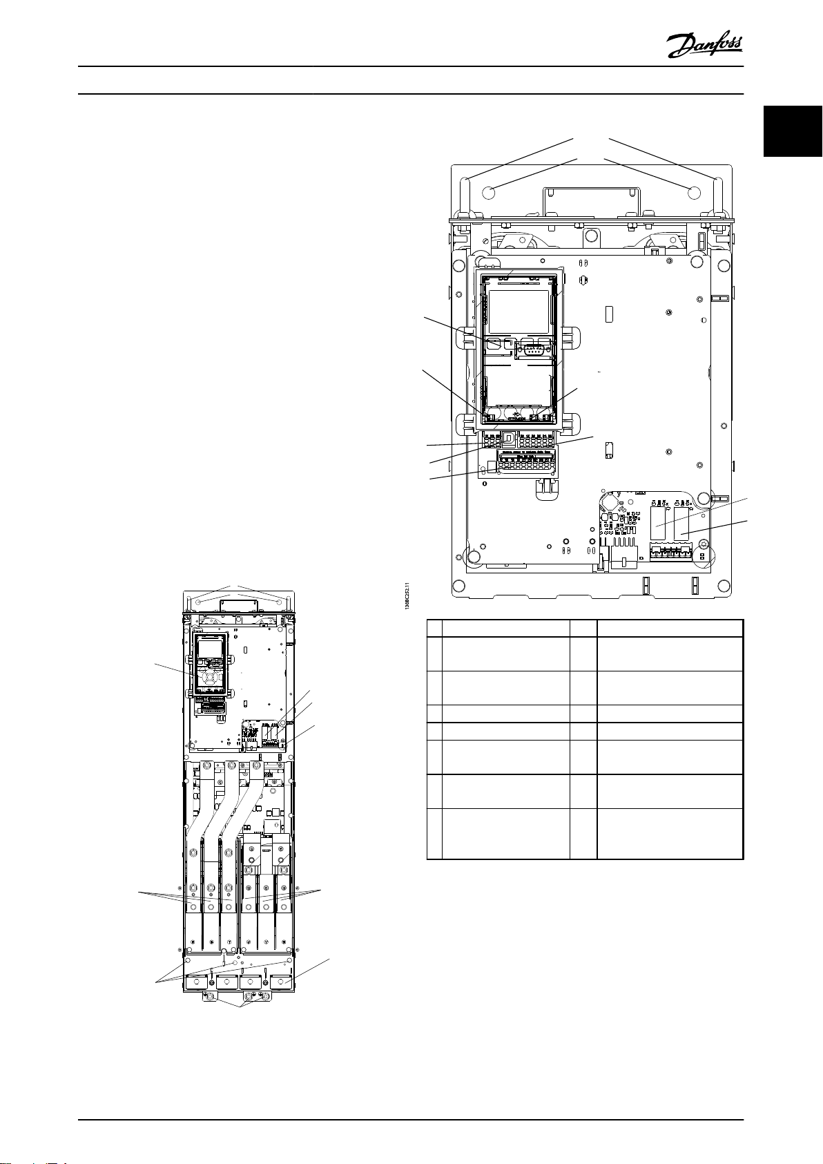
Interior Views
1.5.1
LCP (Local Control Panel) 9 Relay 2 (04, 05, 06)
1
2 RS-485 fieldbus
connector
3 Digital I/O and 24 V
supply
4 Analog I/O connector 12 Cable clamp (PE)
5 USB connector 13 Ground
6 Fieldbus terminal switch 14 Motor output terminals 96
7 Analog switches (A53),
(A54)
8 Relay 1 (01, 02, 03) 16 TB5 (IP21/54 only). Terminal
Illustration 1.2 Close-up View: LCP and Control Functions
10 Lifting ring
11 Mounting slot
(U), 97 (V), 98 (W)
15 Mains input terminals 91
(L1), 92 (L2), 93 (L3)
block for anti-condensation
heater
Illustration 1.1 Interior Components - Enclosure Type D
MG16J202 Danfoss A/S © Rev. 05/2014 All rights reserved. 5
Page 8
130BB019.10
1
2
3
4
5
6
7
8
9
10
130BB020.10
1
2
3
4
5
6
7
8
10
1
Introduction Operating Instructions
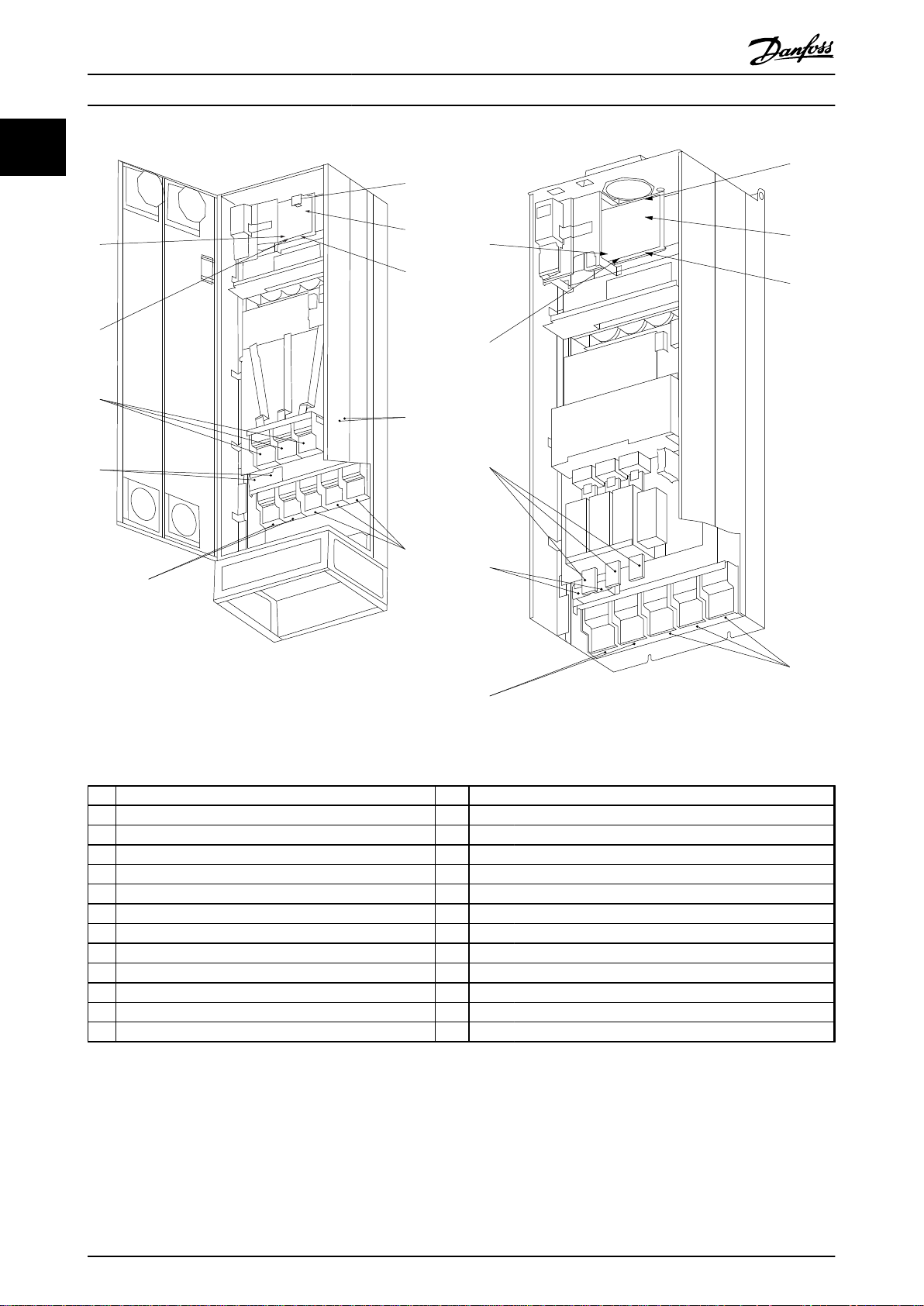
Illustration 1.3 Compact IP21 (NEMA 1) and IP54 (NEMA 12)
Enclosure Type E1
Illustration 1.4 Compact IP00 (Chassis) with Disconnect, Fuse
and RFI Filter, Enclosure Type E2
AUX relay 5) Load sharing
1)
01 02 03 -DC +DC
04 05 06 88 89
2) Temp switch 6) SMPS fuse
106 104 105 7) Fan fuse
3) Mains 8) AUX fan
R S T 100 101 102 103
91 92 93 L1 L2 L1 L2
L1 L2 L3 9) Mains ground
4) Brake 10) Motor
-R +R U V W
81 82 96 97 98
T1 T2 T3
Table 1.1 Legend to Illustration 1.3 and Illustration 1.4
6 Danfoss A/S © Rev. 05/2014 All rights reserved. MG16J202
Page 9
Introduction Operating Instructions
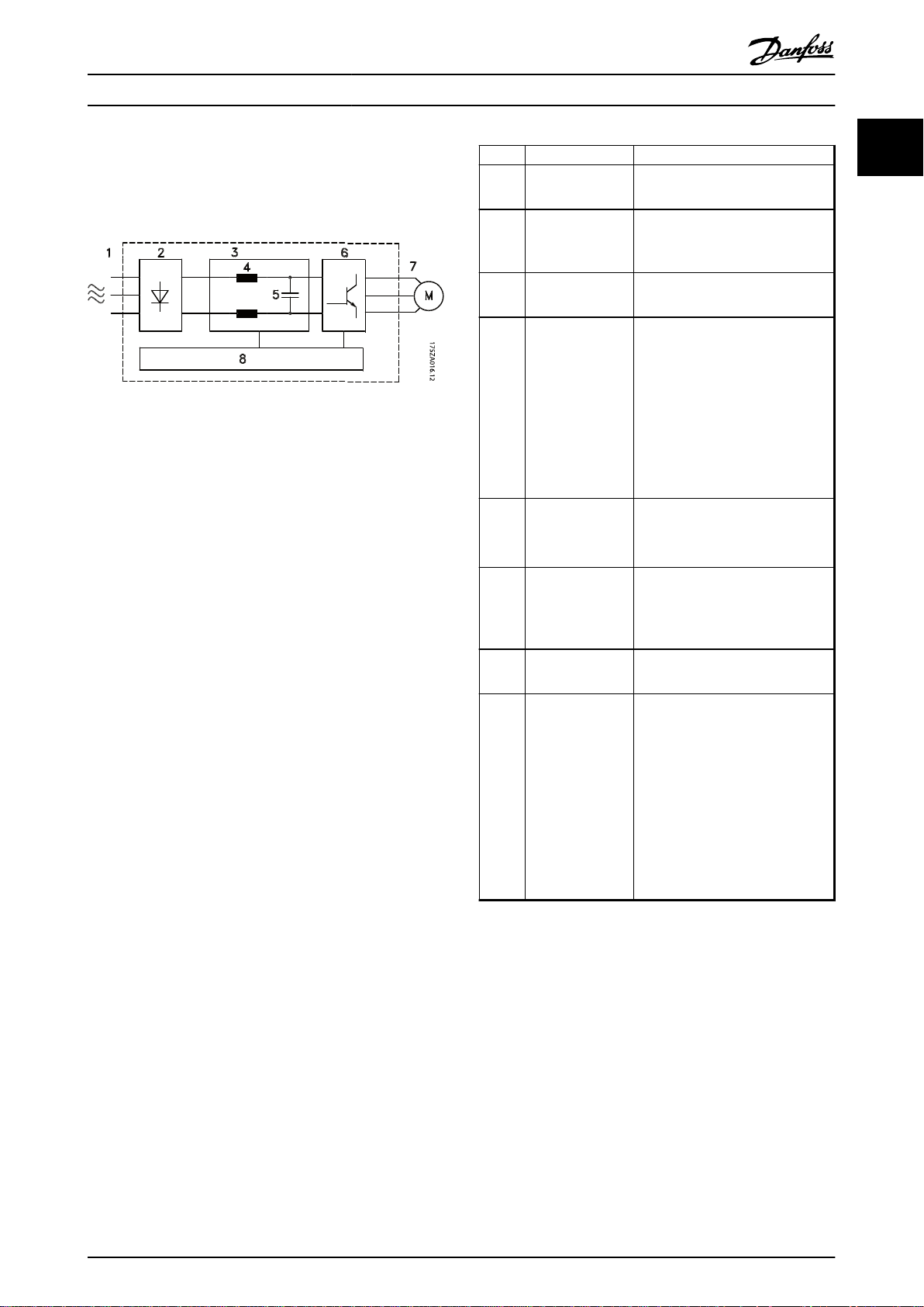
1.6 Internal Controller Functions
Illustration 1.5 is a block diagram of the frequency
converter's internal components.
Illustration 1.5 Frequency Converter Block Diagram
Area Title Functions
3-phase AC mains supply to the
1 Mains input
2 Rectifier
3 DC-bus
4 DC reactors
5 Capacitor bank
6 Inverter
7 Output to motor
8 Control circuitry
•
frequency converter
The rectifier bridge converts the
•
AC input to DC current to
supply inverter power.
Intermediate DC-bus circuit
•
handles the DC current.
Filter the intermediate DC circuit
•
voltage.
Prove line transient protection.
•
Reduce RMS current.
•
Raise the power factor reflected
•
back to the line.
Reduce harmonics on the AC
•
input.
Stores the DC power.
•
Provides ride-through protection
•
for short power losses.
Converts the DC into a
•
controlled PWM AC waveform
for a controlled variable output
to the motor.
Regulated 3-phase output
•
power to the motor
Input power, internal
•
processing, output, and motor
current are monitored to
provide efficient operation and
control.
User interface and external
•
commands are monitored and
performed.
Status output and control can
•
be provided.
1
1
Table 1.2 Legend to Illustration 1.5
MG16J202 Danfoss A/S © Rev. 05/2014 All rights reserved. 7
Page 10

Introduction Operating Instructions
1
1.7 Enclosure Types and Power Ratings
Normal
Overload
[kW]
400 V D1h/
525 V D1h/
690 V D1h/
Table 1.3 kW Rated Frequency Converters
Normal
Overload
[hp]
55 75 90 110 132 160 200 250 315 355 400 450 500 560 630
D1h/
D1h/D3h/
D3h/
D3h/
D5h/D6h
D5h/
D5h/
D6h
D6h
D1h/
D1h/
D3h/
D3h/
D3h/
D5h/
D5h/
D5h/
D6h
D6h
D1h/
D3h/
D3h/
D5h/
D5h/
D6h
75 100 125 150 200 250 300 350 400 450 500 550/
D6h
D6h
D1h/
D3h/
D5h/
D6h
D1h/
D3h/
D5h/
D6h
D1h/
D3h/
D5h/
D6h
D1h/
D3h/
D5h/
D6h
D2h/D4h/
D7h/D8h
D1h/D3h/
D5h/D6h
D2h/D4h/
D7h/D8h
D2h/D4h/
D7h/D8h
D2h/D4h/
D7h/D8h
D2h/
D4h/
D7h/
D8h
D2h/
D4h/
D7h/
D8h
D2h/
D4h/
D7h/
D8h
D2h/D4h/
D7h/D8h
D2h/D4h/
D7h/D8h
D2h/D4h/
D7h/D8h
E1/E2 E1/E2 E1/E2
E1/E2 E1/E2 E1/E2 E1/E2
E1/E2 E1/E2E1/E2 E1/E2
600 650
600
460 V D1h/D3h/
D5h/D6h
575 V D1h/D3h/
D5h/D6h
Table 1.4 Hp Rated Frequency Converters
D1h/
D3h/
D5h/
D6h
D1h/D3h/
D5h/D6h
D1h/D3h/
D5h/D6h
D1h/
D3h/
D5h/
D6h
D1h/
D3h/
D5h/
D6h
D1h/
D3h/
D5h/
D6h
D2h/
D4h/
D7h/
D8h
D2h/
D4h/
D7h/
D8h
D2h/
D4h/
D7h/
D8h
D2h/
D4h/
D7h/
D8h
D2h/
D4h/
D7h/
D8h
D2h/
D2h/
D4h/
D7h/
D8h
E1/E2 E1/E2E1/E2
D4h/
D7h/
D8h
E1/E2 E1/E2 E1/E2 E1/E2
8 Danfoss A/S © Rev. 05/2014 All rights reserved. MG16J202
Page 11
Safety
2 Safety
Operating Instructions
The following symbols are used in this document:
WARNING
Indicates a potentially hazardous situation which could
result in death or serious injury.
CAUTION
Indicates a potentially hazardous situation which could
result in minor or moderate injury. It can also be used to
alert against unsafe practices.
NOTICE
Indicates important information, including situations that
can result in damage to equipment or property.
2.1 Qualified Personnel
Correct and reliable transport, storage, installation,
operation, and maintenance are required for the troublefree and safe operation of the frequency converter. Only
qualified personnel are allowed to install or operate this
equipment.
Qualified personnel are defined as trained staff, who are
authorised to install, commission, and maintain equipment,
systems, and circuits in accordance with pertinent laws and
regulations. Additionally, the personnel must be familiar
with the instructions and safety measures described in this
document.
2.2
Safety Precautions
WARNING
HIGH VOLTAGE
Frequency converters contain high voltage when
connected to AC mains input, DC power supply, or load
sharing. Failure to perform installation, start-up, and
maintenance by qualified personnel can result in death
or serious injury.
Installation, start-up, and maintenance must be
•
performed by qualified personnel only.
WARNING
UNINTENDED START
When the frequency converter is connected to AC mains,
or DC power supply, the motor may start at any time.
Unintended start during programming, service or repair
work can result in death, serious injury, or property
damage. The motor can start by means of an external
switch, a serial bus command, an input reference signal
from the LCP, or after a cleared fault condition.
To prevent unintended motor start:
Disconnect the frequency converter from mains.
•
Press [Off/Reset] on the LCP, before
•
programming parameters.
The frequency converter, motor, and any driven
•
equipment must be fully wired and assembled
when the frequency converter is connected to
AC mains, or DC power supply.
WARNING
DISCHARGE TIME
The frequency converter contains DC-link capacitors,
which can remain charged even when the frequency
converter is not powered. Failure to wait the specified
time after power has been removed before performing
service or repair work, could result in death or serious
injury.
Stop the motor.
•
Disconnect the AC mains, permanent magnet
•
type motors, and remote DC-link power
supplies, including battery back-ups, UPS, and
DC-link connections to other frequency
converters.
Wait for the capacitors to discharge fully before
•
performing any service or repair work. The
duration of waiting time is specified in
Table 2.1.
Voltage [V] Minimum waiting time (minutes)
20 40
380-480 110-315 kW 355-450 kW
525-690 55-400 kW 450-630 kW
High voltage may be present even when the warning LED
indicator lights are off.
2 2
Table 2.1 Discharge Time
MG16J202 Danfoss A/S © Rev. 05/2014 All rights reserved. 9
Page 12
Safety Operating Instructions
WARNING
LEAKAGE CURRENT HAZARD
22
Leakage currents exceed 3.5 mA. Failure to ground the
frequency converter properly can result in death or
serious injury.
Ensure correct grounding of the equipment by
•
a certified electrical installer.
WARNING
EQUIPMENT HAZARD
Contact with rotating shafts and electrical equipment
can result in death or serious injury.
Ensure that only trained and qualified
•
personnel perform installation, start up, and
maintenance.
Ensure that electrical work conforms to national
•
and local electrical codes.
Follow the procedures in this manual.
•
CAUTION
UNINTENDED MOTOR ROTATION
WINDMILLING
Unintended rotation of permanent magnet motors can
result in serious injury or equipment damage.
Ensure that permanent magnet motors are
•
blocked to prevent unintended rotation.
CAUTION
INTERNAL FAILURE HAZARD
An internal failure in the frequency converter can result
in serious injury, when the frequency converter is not
properly closed.
Ensure that all safety covers are in place and
•
securely fastened, before applying power.
10 Danfoss A/S © Rev. 05/2014 All rights reserved. MG16J202
Page 13
105
298
[11.7]
404
[15.9]
130BC519.10
130BC520.10
105
523
[20.6]
395
[15.6]
748
(29.5)
579
(22.8)
176FA276.12
≤105,0°
Installation Operating Instructions
3 Installation
3.1 Pre-Installation
3.1.1 Planning the Installation Site
NOTICE
Plan the installation site of the frequency converter
before commencing the installation. Neglecting this may
result in extra work during and after installation.
Select the best possible operation site by considering
the following (see details on the following pages and
the respective Design Guides):
Ambient operating temperature
•
Installation method
•
How to cool the unit
•
Position of the frequency converter
•
Cable routing
•
Ensure that the power source supplies the correct
•
voltage and necessary current.
Ensure that the motor current rating is within the
•
maximum current from the frequency converter.
If the frequency converter is without built-in
•
fuses, ensure that the external fuses are rated
correctly.
3 3
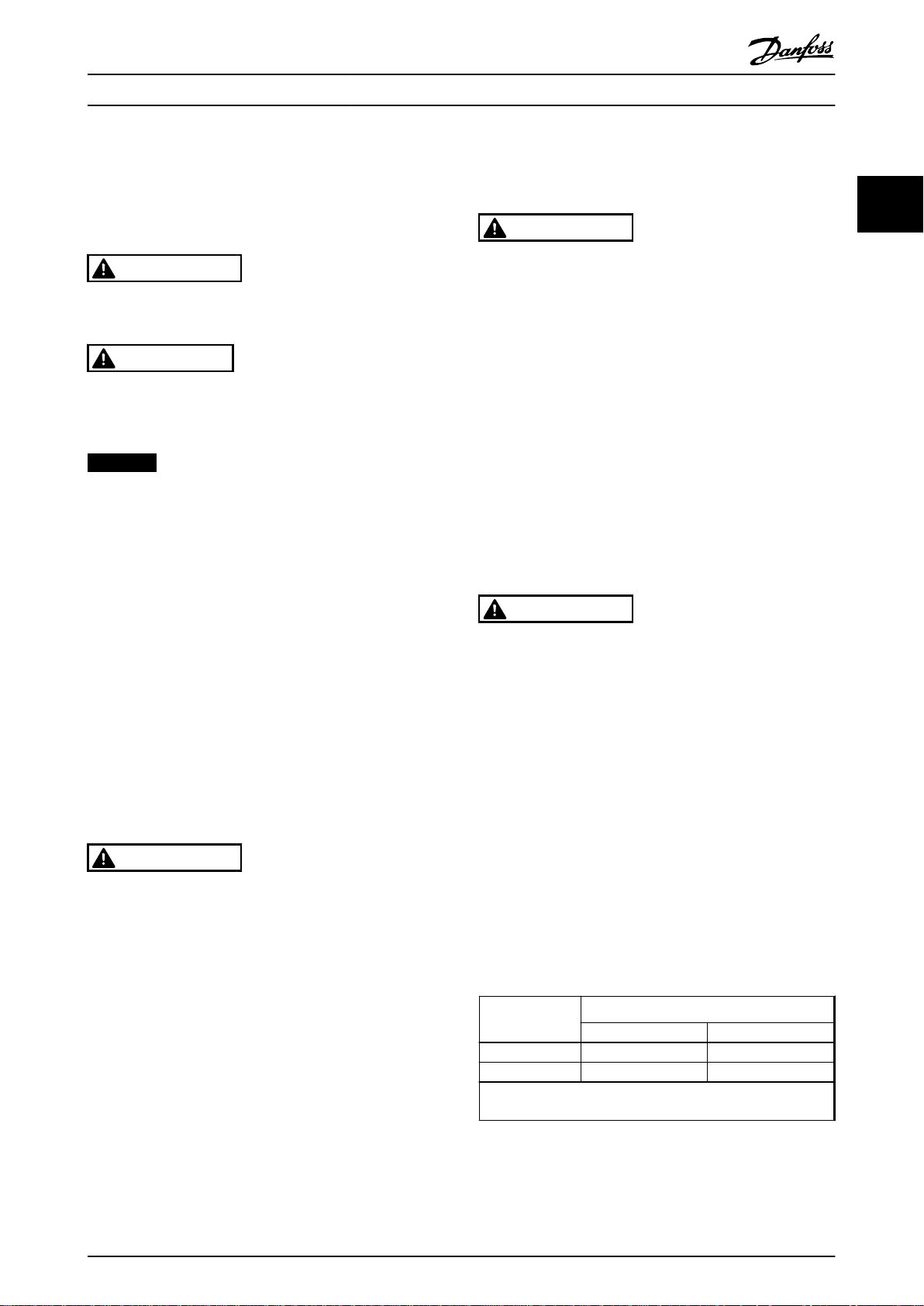
Illustration 3.1 Front Clearance of IP21/IP54 Rated Enclosure
Types D1h, D5h, and D6h
Voltage [V] Altitude restrictions
380-690 At altitudes above 2000 m, contact Danfoss
regarding PELV
Table 3.1 Installation at High Altitudes
General Considerations
3.1.2
Wire access
Ensure that proper cable access is present including
necessary bending allowance. As the IP00/IP20 enclosure is
open to the bottom, cables must be fixed to the back
panel of the enclosure where the frequency converter is
mounted, i.e. by using cable clamps.
CAUTION
All cable lugs/shoes must mount within the width of the
terminal bus bar.
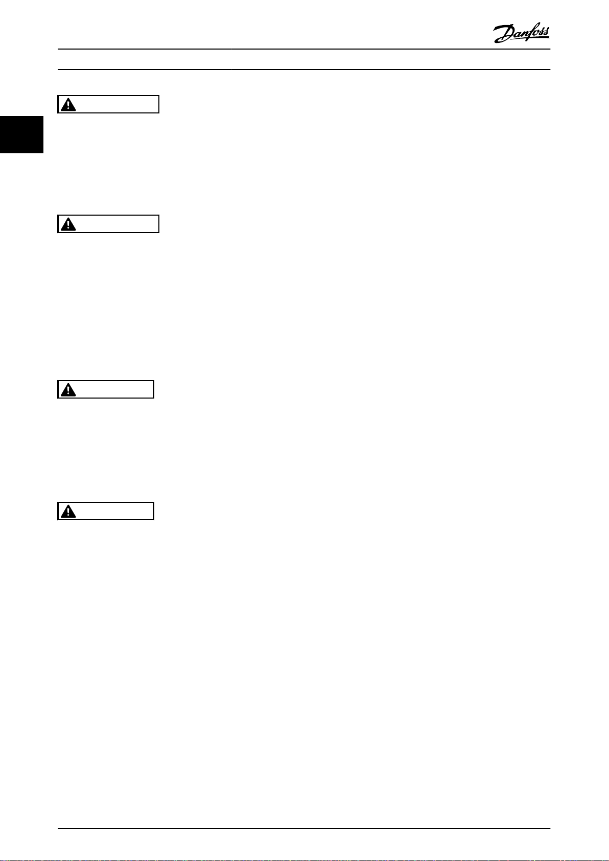
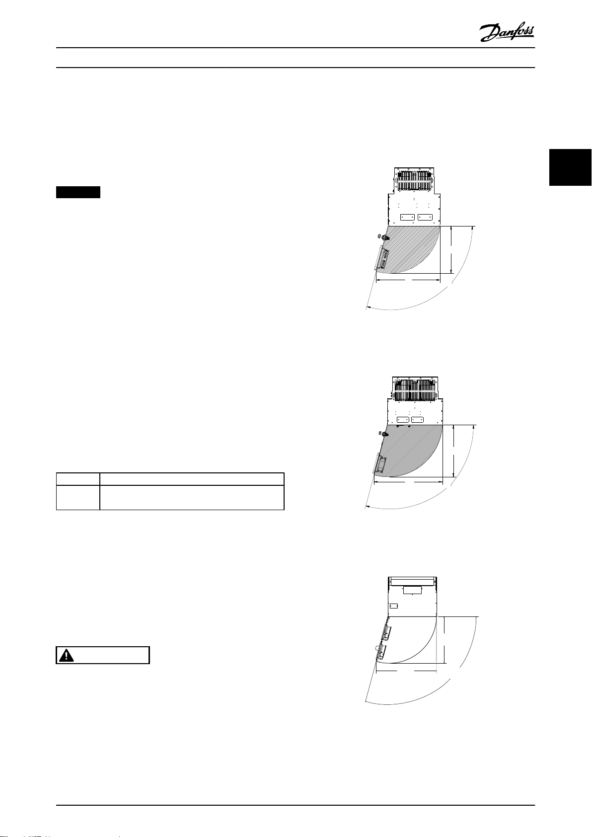
Space
Ensure proper space above and below the frequency
converter to allow airflow and cable access. In addition
space in front of the unit must be considered to enable
opening of the panel door, see Illustration 3.1 to
Illustration 3.3.
Illustration 3.2 Front Clearance of IP21/IP54 Rated Enclosure
Types D2h, D7h, and D8h
Illustration 3.3 Front Clearance of IP21/IP54 Rated Enclosure
Type E1
MG16J202 Danfoss A/S © Rev. 05/2014 All rights reserved. 11
Page 14

Installation
Operating Instructions
3.1.3 Tools Required for Installation
Drill with 10 or 12 mm drill
•
Tape measure
•
Wrench with relevant metric sockets (7-17 mm)
•
33
Extensions to wrench
•
Sheet metal punch for conduits or cable glands
•
in IP21/Nema 1 and IP54 units
Lifting bar to lift the unit (rod or tube max. Ø 5
•
mm (1 inch), able to lift minimum 400 kg (880
lbs).
Crane or other lifting aid to place the frequency
•
converter in position
A Torx T50 tool is needed to install the E1 in IP21
•
and IP54 enclosure types.
3.2 Pre-installation Checklist
Before unpacking the frequency converter, ensure
•
that the packaging is intact. If any damage has
occurred, immediately contact the shipping
company to claim the damage.
Unpack the frequency converter as close as
•
possible to the final installation site.
Ensure the model number number on the
•
nameplate corresponds to the model number on
the order.
Ensure that each of the following are rated for
•
the same voltage:
Mains (power)
•
Frequency converter
•
Motor
•
Ensure that the frequency converter output
•
current rating is equal to or greater than the
motor full load current for peak motor
performance.
Motor size and frequency converter
•
power must match for proper overload
protection.
If frequency converter rating is less than
•
motor, full motor output cannot be
achieved.
3.3
Mechanical Installation
3.3.1 Cooling
Provide top and bottom clearance for air cooling.
•
Generally, 225 mm (9 in) is required.
Improper mounting can result in overheating and
•
reduced performance.
Consider derating for temperatures starting
•
between 45 °C (113 °F) and 50 °C (122 °F) and
elevation 1000 m (3300 ft) above sea level. See
VLT® Refrigeration Drive FC 103 Design Guide for
detailed information.
The high-power frequency converters utilise a backchannel cooling concept that removes heat sink cooling
air. Approximately 90% of the heat is lead out of the back
channel of the frequency converters. The back-channel air
can be redirected from the panel or room using one of the
kits below.
Duct cooling
A back-channel cooling kit is available to direct the heat
sink cooling air out of the panel when an IP20/chassis
frequency converter is installed in a Rittal enclosure. Use of
this kit reduces the heat in the panel and smaller door fans
can be specified on the enclosure.
Cooling out the back (top and bottom covers)
The back-channel cooling air can be ventilated out of the
room so that the heat from the back channel is not
dissipated into the control room.
NOTICE
A door fan(s) is required on the enclosure to remove the
heat not contained in the back channel of the frequency
converters and any additional losses generated by other
components inside the enclosure. Calculate the total
required air flow so that the appropriate fans can be
selected. A cooling clearance of 225 mm is required
above the frequency converter.
Airflow
Secure the necessary airflow over the heat sink. The flow
rate is shown in Table 3.2.
12 Danfoss A/S © Rev. 05/2014 All rights reserved. MG16J202
Page 15

176FA245.10
Installation Operating Instructions
NOTICE
The fan runs for the following reasons:
AMA
•
DC hold
•
Pre-mag
•
DC brake
•
60% of nominal current is exceeded
•
Specific heat sink temperature exceeded (power
•
size dependent)
Specific power card ambient temperature
•
exceeded (power size dependent)
Specific control card ambient temperature
•
exceeded
Enclosure type Door fan/top fan Heat sink fan
D1h/D3h/D5h/D6h
D2h/D4h/D7h/D8h
E1 P450T7, P500T7
E1 P355-P450T4,
P560-P630T7
E2 P450T7, P500T7
E2 P355-P450T4,
P560-P630T7
Table 3.2 Airflow
102 m3/hr (60 CFM) 420 m3/hr (250 CFM)
204 m3/hr (120 CFM) 840 m3/hr (500 CFM)
340 m3/hr (200 CFM) 1105 m3/hr (650
CFM)
340 m3/hr (200 CFM) 1445 m3/hr (850
CFM)
255 m3/hr (150 CFM) 1105 m3/hr (650
CFM)
255 m3/hr (150 CFM) 1445 m3/hr (850
CFM)
Lifting
3.3.2
Always lift the frequency converter using the dedicated
lifting eyes. Use a bar to avoid bending the lifting holes.
Illustration 3.4 Recommended Lifting Method
WARNING
RISK OF INJURY OR DEATH
The lifting bar must be able to handle the weight of the
frequency converter to ensure that it will not break
during lifting.
See Mechanical Dimensions for the weight of the
•
different enclosure types.
Maximum diameter for bar is 2.5 cm (1 inch).
•
The angle from the top of the frequency
•
converter to the lifting cable should be 60° or
greater.
Failure to follow recommendations could result in death
or serious injury.
3 3
MG16J202 Danfoss A/S © Rev. 05/2014 All rights reserved. 13
Page 16
Installation Operating Instructions
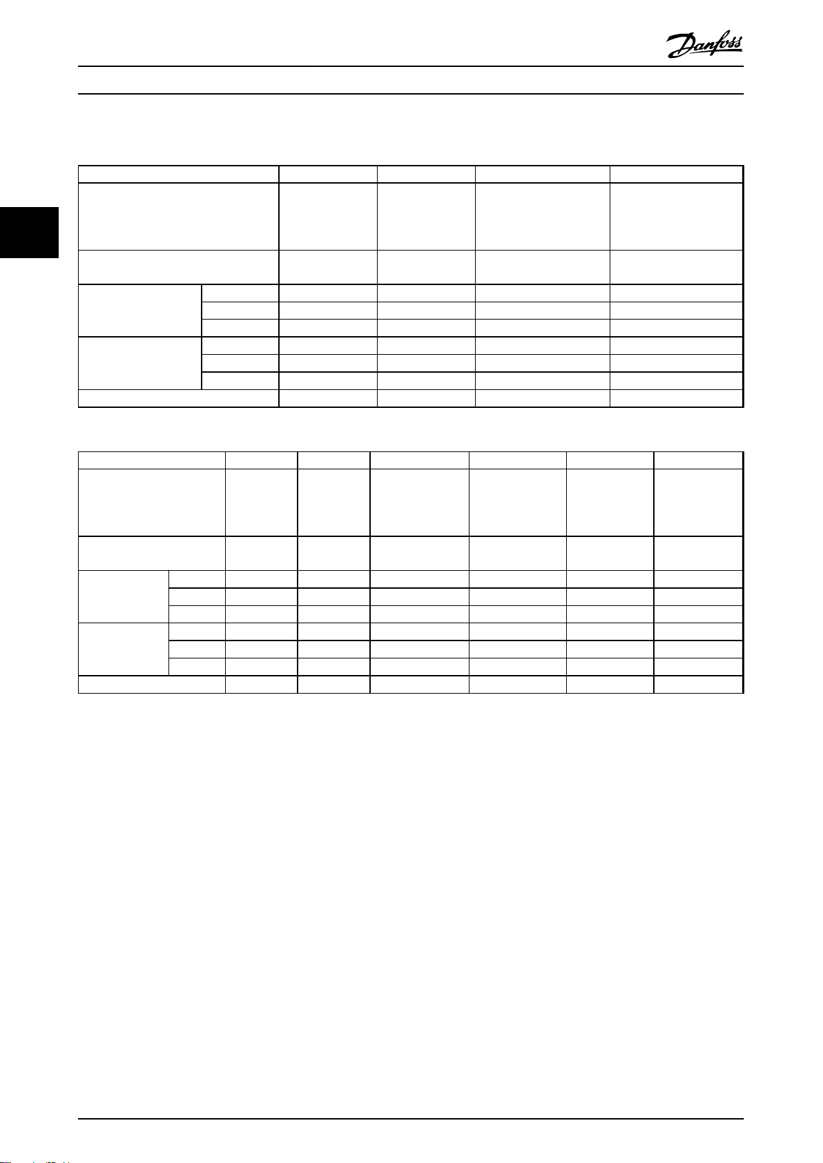
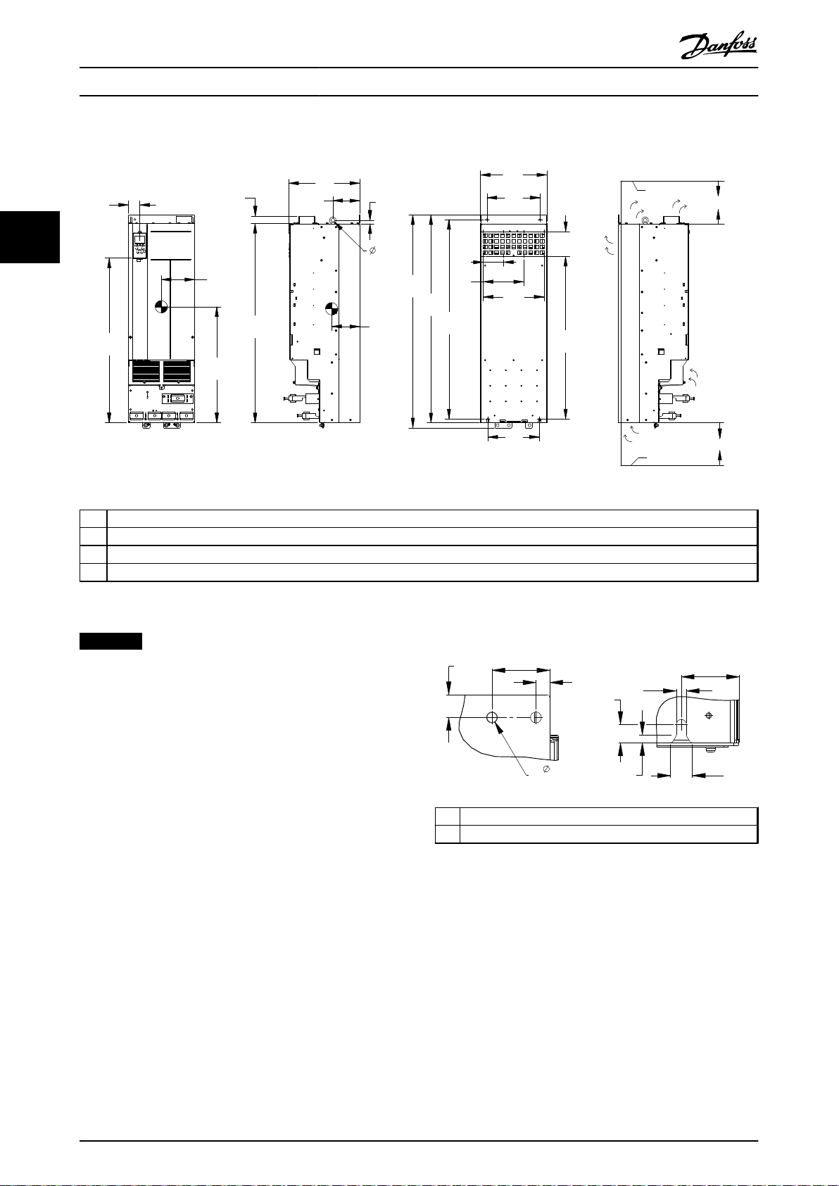
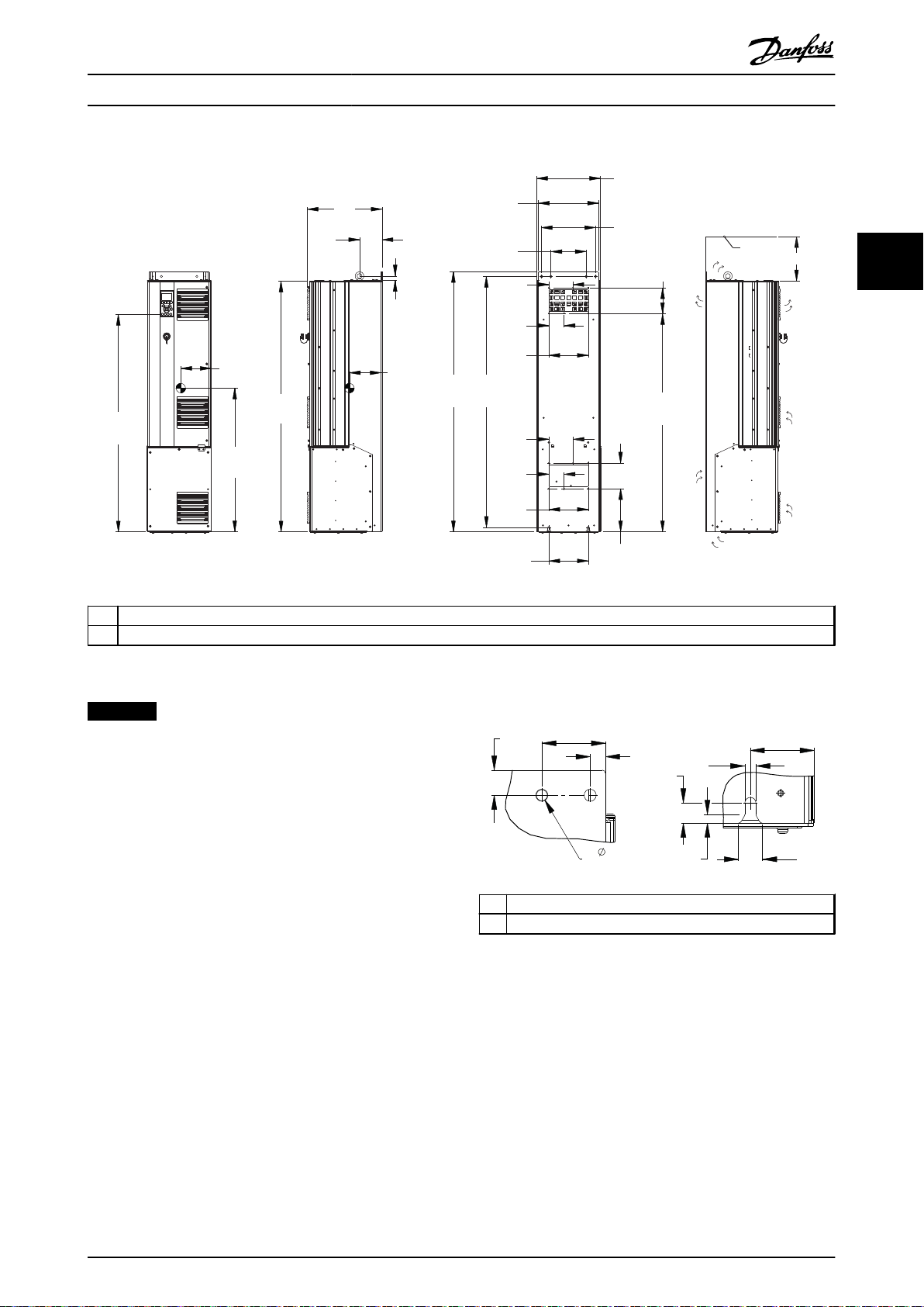
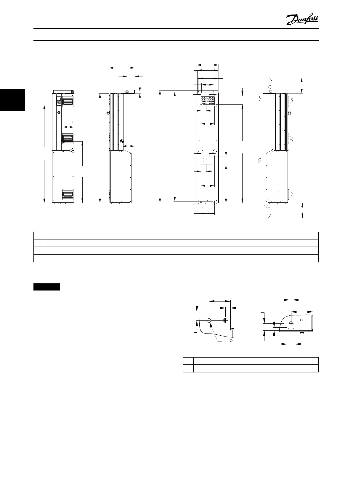
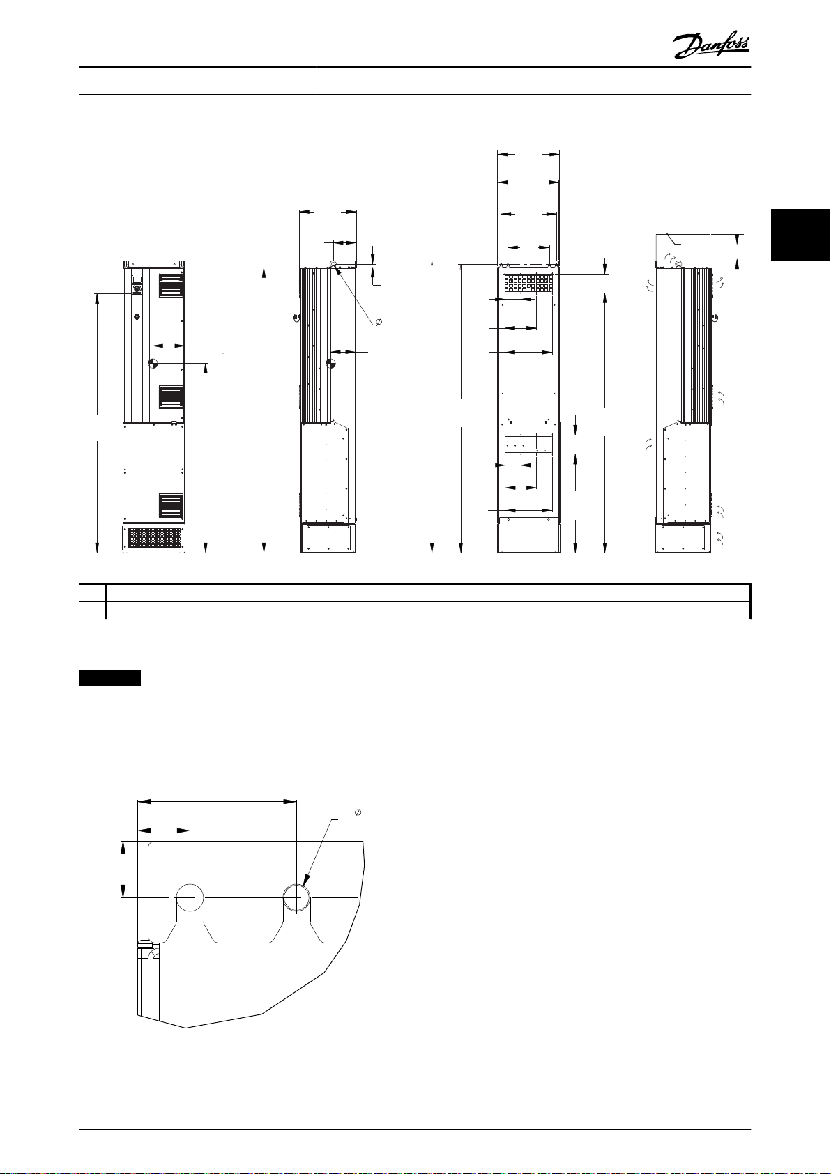
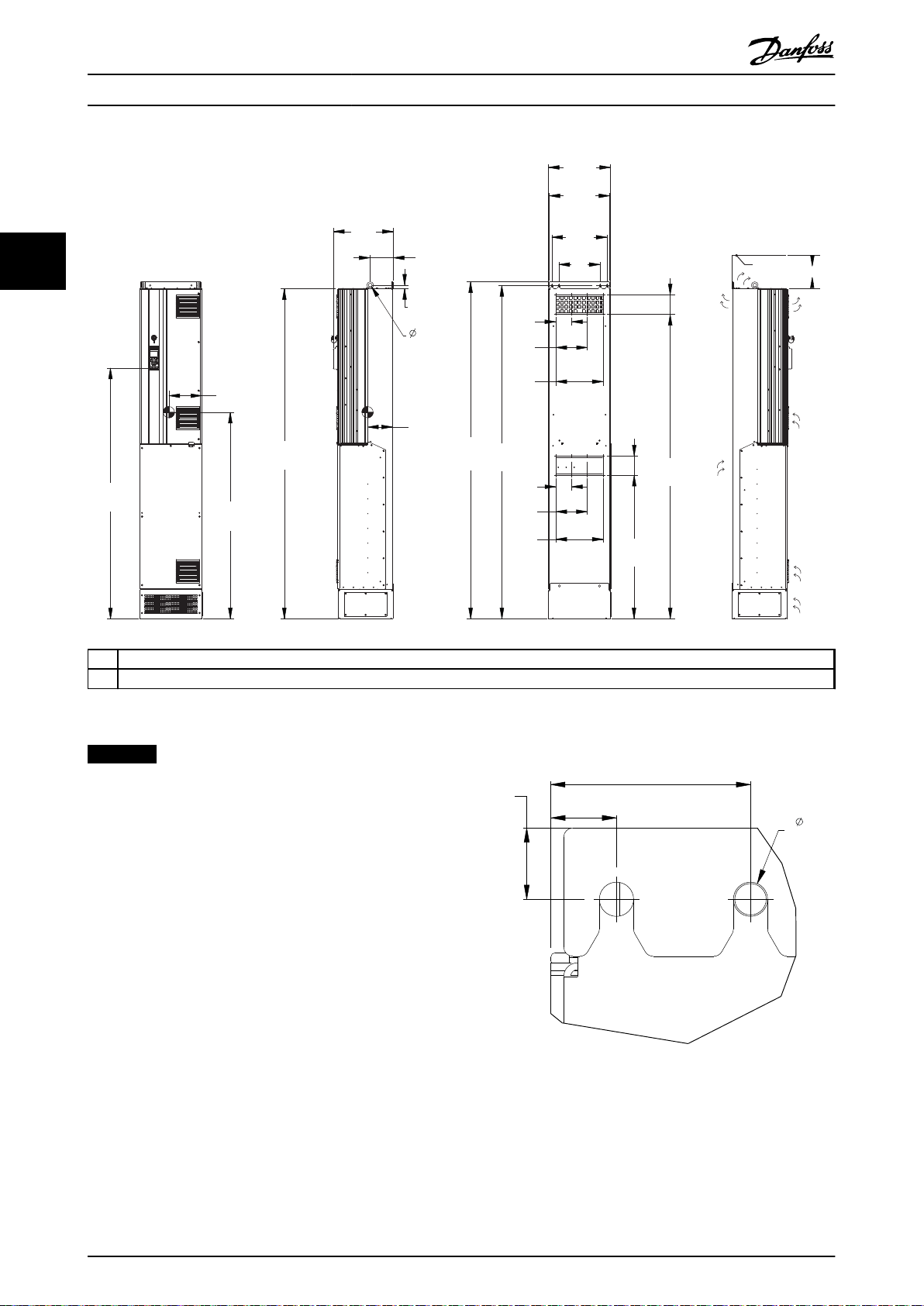
3.3.3 Mechanical Dimensions
Enclosure type D1h D2h D3h D4h
110-160 kW
(380-480 V)
75-160 kW
33
IP
NEMA
Shipping dimensions
[mm]
Drive dimensions [mm]
Max weight [kg] 98 164 98 164
Table 3.3 Mechanical Dimensions, Enclosure Types D1h-D4h
Enclosure type D5h D6h D7h D8h E1 E2
IP
NEMA
Shipping
dimensions [mm]
Drive
dimensions [mm]
Max weight [kg] 116 129 200 225 313 277
Height 587 587 587 587
Width 997 1170 997 1170
Depth 460 535 460 535
Height 901 1107 909 1122
Width 325 420 250 350
Depth 378 378 375 375
110-160 kW
(380-480 V)
75-160 kW
(525-690 V)
21/54
Type 1/12
Height 660 660 660 660 840 831
Width 1820 1820 2470 2470 2197 1705
Depth 510 510 590 590 736 736
Height 1324 1663 1978 2284 2000 1547
Width 325 325 420 420 600 585
Depth 381 381 386 406 494 498
(525-690 V)
21/54
Type 1/12
110-160 kW
(380-480 V)
75-160 kW
(525-690 V)
21/54
Type 1/12
200-315 kW
(380-480 V)
200-400 kW
(525-690 V)
21/54
Type 1/12
200-315 kW
(380-480 V)
200-400 kW
(525-690 V)
21/54
Type 1/12
110-160 kW
(380-480 V)
75-160 kW
(525-690 V)
Chassis
200-315 kW
(380-480 V)
200-400 kW
(525-690 V)
21/54
Type 1/12
20
355-450 kW
(380-480 V)
450-630 kW
(525-690 V)
21, 54
Type 12
200-315 kW
(380-480 V)
200-400 kW
(525-690 V)
20
Chassis
355-450 kW
(380-480 V)
450-630 kW
(525-690 V)
00
Chassis
Table 3.4 Mechanical Dimensions, Enclosure Types D5h-D8h, E1-E2
14 Danfoss A/S © Rev. 05/2014 All rights reserved. MG16J202
Page 17
130
[5.1]
656
[25.8]
844
[33.2]
901
[35.5]
148
[5.8]
18
[0.7]
82
[3.2]
20
[0.8]
378
[14.9]
507
[20.0]
164
[6.5]
674
[26.5]
99
[3.9]
200
[7.9]
200
[7.9]
180
[7.1]
246
[9.7]
325
[12.8]
78
[3.1]
123
[4.8]
844
[33.2]
561
[22.1]
130BC515.11
1
4
2
3
1
33
[1.3]
63
[2.5]
24
[0.9]
22
[0.9]
25
[1.0]
11
[0.4]
10
[0.4]
11
[0.4]
2
130BD514.10
Installation Operating Instructions
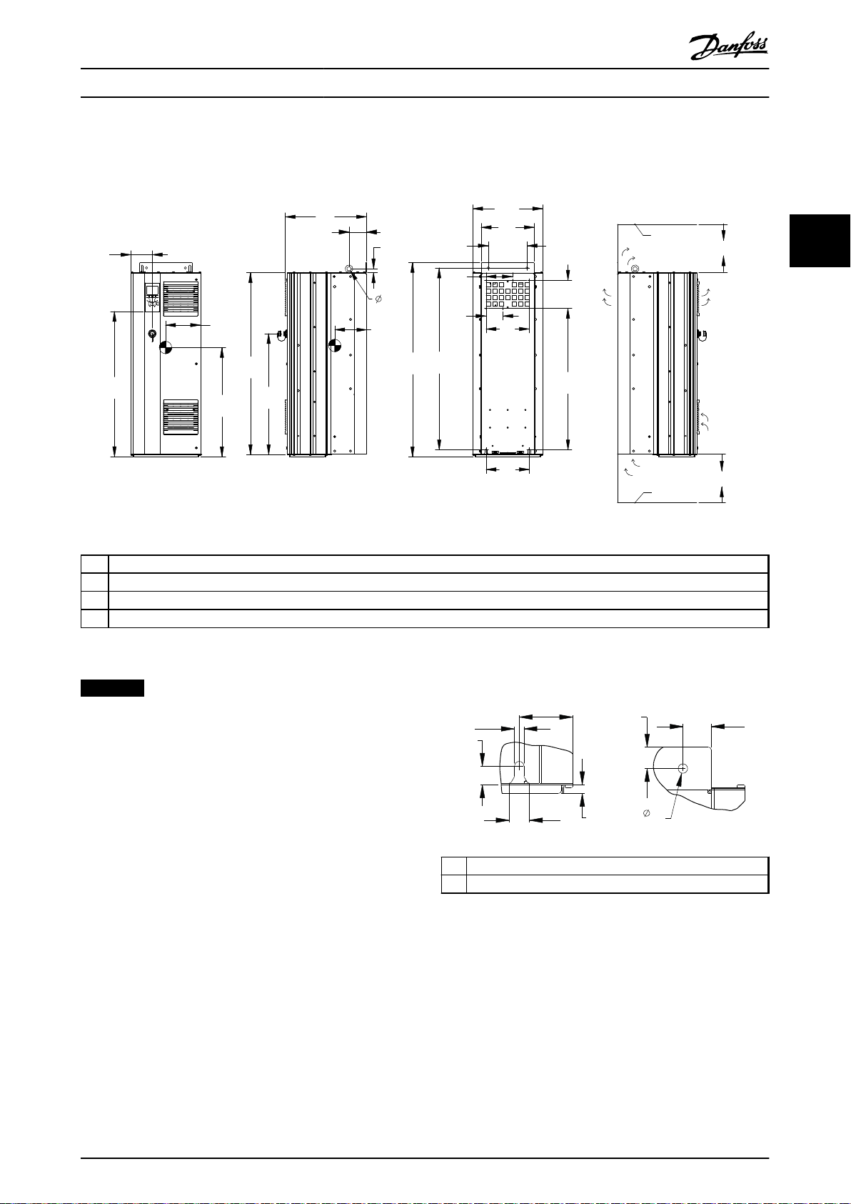
All dimensions are in mm [in]
3 3
1 Ceiling
2 Air space outlet minimum 225 mm [8.9 in]
3 Air space inlet minimum 225 mm [8.9 in]
4 Floor
Illustration 3.5 Mechanical Dimensions, D1h
NOTICE
If using a kit to direct the airflow from the heat sink to
the outside vent on the back of the frequency converter,
the required ceiling clearance is 100 mm.
1 Bottom mounting slot detail
MG16J202 Danfoss A/S © Rev. 05/2014 All rights reserved. 15
2 Top mounting hole detail
Illustration 3.6 Detail Dimensions, D1h
Page 18
211
[8.3]
623
[24.5]
148
[5.8]
280
[11.0]
346
[13.6]
420
[16.5]
1051
[41.4]
1107
[43.6]
857
[33.7]
130
[5.1]
320
[12.6]
271
[10.7]
20
[0.8]
18
[0.7]
379
[14.9]
96
[3.8]
879
[34.6]
142
[5.6]
107
[4.2]
213
[8.4]
1050
[41.3]
718
[28.3]
130BC516.11
1
4
2
3
1
2
33
[1.3]
25
[1.0]
24
[0.9]
20
[0.8]
75
[2.9]
11
[0.4]
9
[0.3]
11
[0.4]
12
[0.5]
130BD515.10
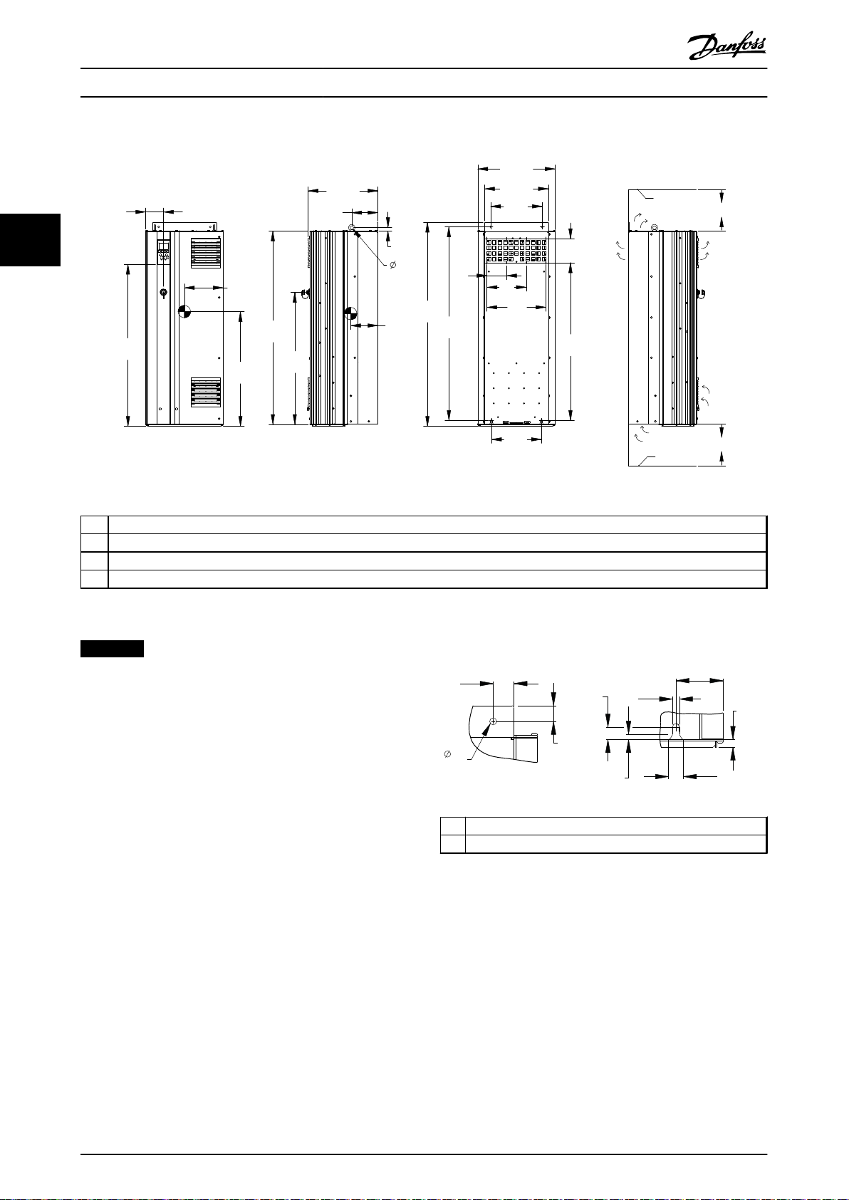
Installation Operating Instructions
33
1 Ceiling
2 Air space outlet minimum 225 mm [8.9 in]
3 Air space inlet minimum 225 mm [8.9 in]
4 Floor
Illustration 3.7 Mechanical Dimensions, D2h
NOTICE
If using a kit to direct the airflow from the heat sink to
the outside vent on the back of the frequency converter,
the required ceiling clearance is 100 mm.
1 Top mounting hole detail
2 Bottom mounting slot detail
Illustration 3.8 Detail Dimensions, D2h
16 Danfoss A/S © Rev. 05/2014 All rights reserved. MG16J202
Page 19
130BC517.11
250
[9.8]
844
[33.2]
889
[35.0]
909
[35.8]
130
[5.1]
656
[25.8]
200
[7.9]
180
[7.1]
495
[19.5]
660
[26.0]
61
[2.4]
148
[5.8]
82
[3.2]
18
[0.7]
375
[14.8]
20
[0.8]
200
[7.9]
77.5
[3.1]
122.5
[4.8]
26
[1.0]
844
[33.2]
128
[5.0]
1
4
2
3
1 2
33
[1.3]
25
[1.0]
24
[0.9]
20
[0.8]
40
[1.6]
11
[0.4]
9
[0.3]
11
[0.4]
130BD517.10
Installation Operating Instructions
3 3
1 Ceiling
2 Air space outlet minimum 225 mm [8.9 in]
3 Air space inlet minimum 225 mm [8.9 in]
4 Floor
Illustration 3.9 Mechanical Dimensions, D3h
NOTICE
If using a kit to direct the airflow from the heat sink to
the outside vent on the back of the frequency converter,
the required ceiling clearance is 100 mm.
1 Top mounting hole detail
2 Bottom mounting slot detail
Illustration 3.10 Detail Dimensions, D3h
MG16J202 Danfoss A/S © Rev. 05/2014 All rights reserved. 17
Page 20
130BC518.11
280
[11.0]
857
[33.7]
130
[5.1]
320
[12.6]
1051
[41.4]
1096
[43.1]
1122
[44.2]
148
[5.8]
18
[0.7]
142
[5.6]
375
[14.8]
611
[24.1]
176
[6.9]
868
[34.2]
59
[2.3]
271
[10.7]
350
[13.8]
107
[4.2]
213
[8.4]
39
[1.5]
1050
[41.3]
20
[0.8]
1
4
2
3
64
[2.5]
63
[2.5]
24
[0.9]
9
[0.3]
25
[1.0]
11
[0.4]
20
[0.8]
15
[0.6]
11
[0.4]
4X
1 2
130BD518.10
Installation Operating Instructions
33
1 Ceiling
2 Air space outlet minimum 225 mm [8.9 in]
3 Air space inlet minimum 225 mm [8.9 in]
4 Floor
Illustration 3.11 Mechanical Dimensions, D4h
NOTICE
If using a kit to direct the airflow from the heat sink to
the outside vent on the back of the frequency converter,
the required ceiling clearance is 100 mm.
1 Top mounting hole detail
2 Bottom mounting slot detail
Illustration 3.12 Detail Dimensions, D4h
18 Danfoss A/S © Rev. 05/2014 All rights reserved. MG16J202
Page 21
130BD463.10
149
[5.9]
731
[28.8]
1107
[43.6]
381
[15]
115
[4.5]
23
[0.9]
16.1
[6.3]
1277
[50.3]
123
[4.8]
1324
[52.1]
1276
[50.2]
200
[7.9]
78
[3.1]
123
[4.8]
78
[3.1]
200
[7.9]
220
[8.7]
130
[5.1]
200
[7.9]
1111
[43.7]
130
[5.1]
325
[12.8]
306
[12.1]
276
[10.9]
180
[7.1]
2
1
64
[2.5]
63
[2.5]
24
[0.9]
9
[0.3]
25
[1.0]
11
[0.4]
20
[0.8]
15
[0.6]
11
[0.4]
4X
1 2
130BD518.10
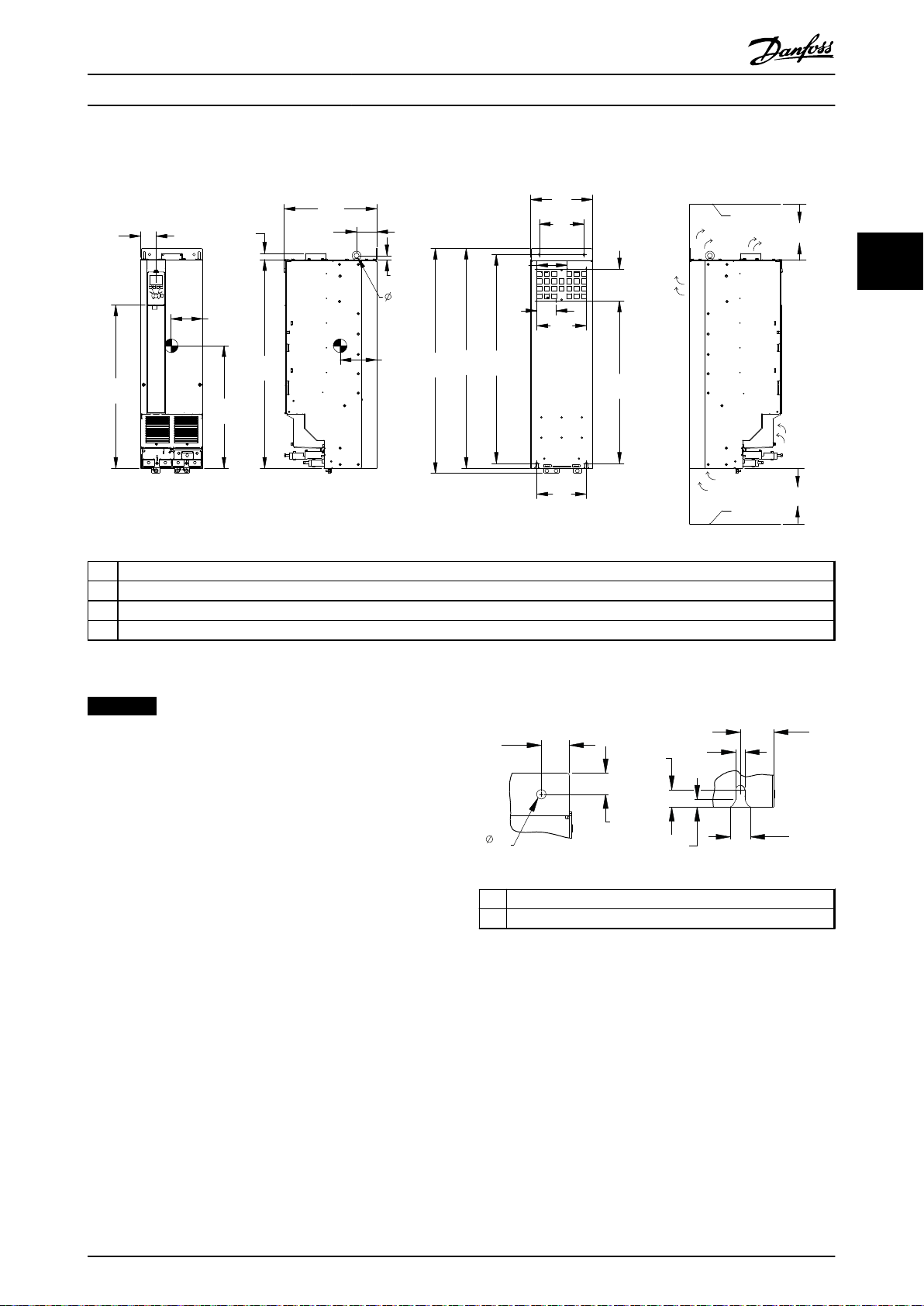
Installation Operating Instructions
3 3
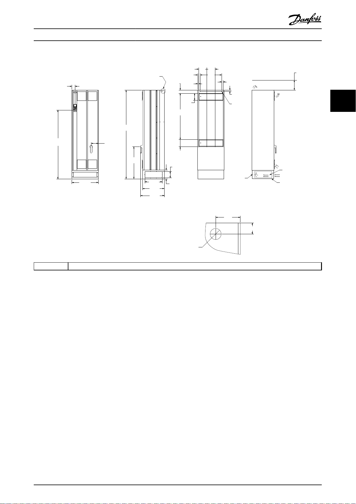
1 Ceiling
2 Air space outlet minimum 225 mm [8.9 in]
Illustration 3.13 Mechanical Dimensions, D5h
NOTICE
If using a kit to direct the airflow from the heat sink to
the outside vent on the back of the frequency converter,
the required ceiling clearance is 100 mm.
1 Top mounting hole detail
2 Bottom mounting slot detail
Illustration 3.14 Detail Dimensions, D5h
MG16J202 Danfoss A/S © Rev. 05/2014 All rights reserved. 19
Page 22
130BD464.10
1447
[57.0]
909
[35.8]
159
[6.3]
381
[15.0]
115
[4.5]
23
[0.9]
1663
[65.5]
1615
[63.6]
1452
[57.2]
559
[22.0]
130
[5.1]
200
[7.9]
123
[4.8]
78
[3.1]
200
[7.9]
325
[12.8]
306
[12.1]
276
[10.9]
180
[7.1]
130
[5.1]
1617
[63.7]
181
[7.1]
200
[7.9]
78
[3.1]
123
[4.8]
1
2
3
4
63.5
[3]
63
[2.5]
24
[0.9]
9
[0.3]
25
[1.0]
11
[0.4]
20
[0.8]
15
[0.6]
1 2
11
[0.4]
4X
130BD519.10
Installation Operating Instructions
33
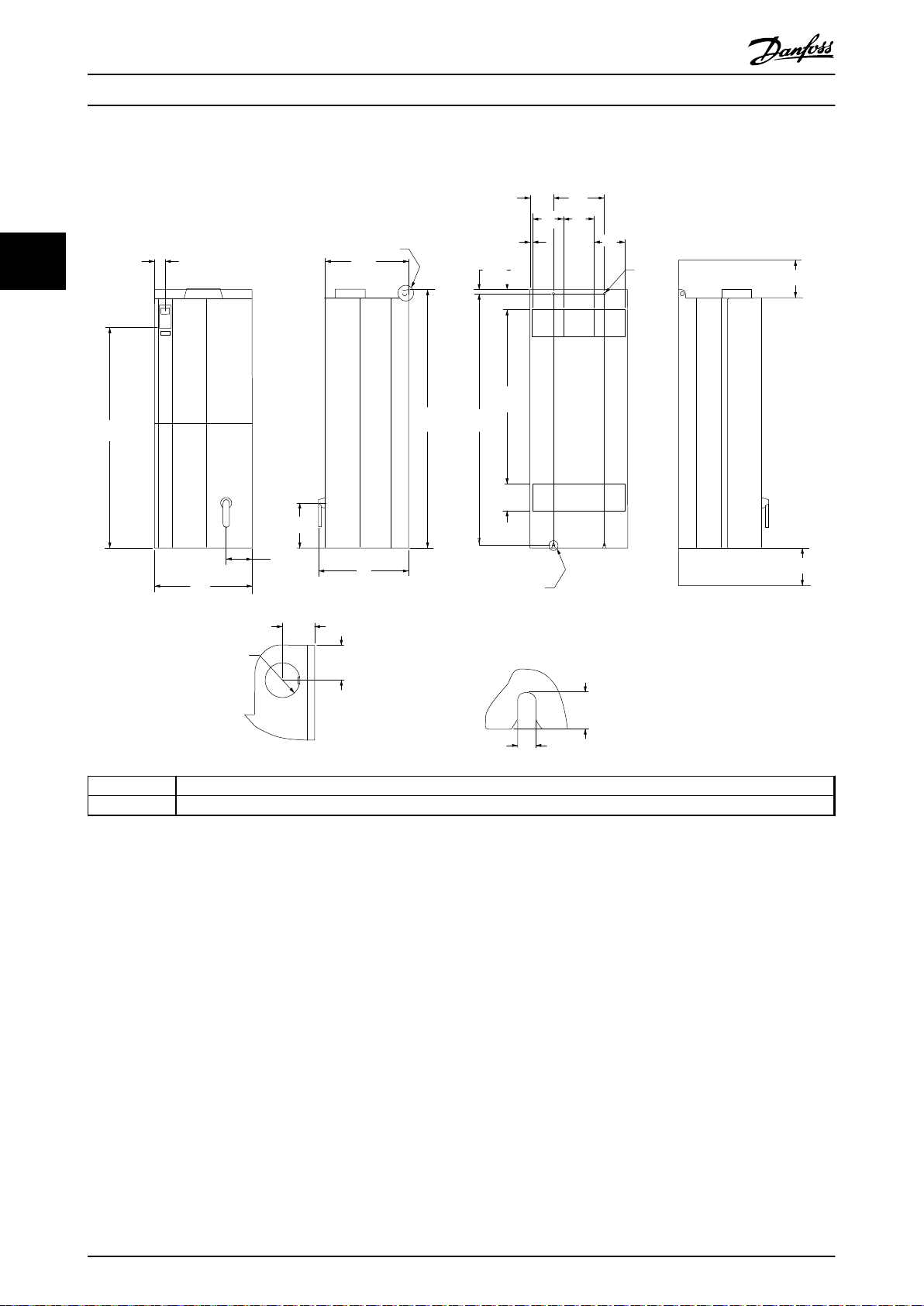
1 Ceiling
2 Air space outlet minimum 225 mm [8.9 in]
3 Air space intlet minimum 225 mm [8.9 in]
4 Floor
Illustration 3.15 Mechanical Dimensions, D6h
NOTICE
If using a kit to direct the airflow from the heat sink to
the outside vent on the back of the frequency converter,
the required ceiling clearance is 100 mm.
1 Top mounting hole detail
2 Bottom mounting slot detail
Illustration 3.16 Detail Dimensions, D6h
20 Danfoss A/S © Rev. 05/2014 All rights reserved. MG16J202
Page 23
1754
[69.1]
209
[8.2]
1282
[50.5]
386
[15.2]
156
[6.2]
23
[0.9]
25
[1]
161
[6.3]
1931
[76]
170
[4.2]
213
[8.4]
320
[12.6]
1978
[77.9]
1953
[76.9]
107
[4.2]
213
[8.4]
320
[12.6]
1
280
[11]
374
[14.7]
411
[16.2]
420
[16.5]
130
[5.1]
1760
[69.3]
130
[5.1]
668
[26.3]
130BD465.10
2
70
[2.8]
25
[1.0]
23
[0.9]
11
[0.4]
4X
130BD520.10
Installation Operating Instructions
3 3
1 Ceiling
2 Air space outlet minimum 225 mm [8.9 in]
Illustration 3.17 Mechanical Dimensions, D7h
NOTICE
If using a kit to direct the airflow from the heat sink to
the outside vent on the back of the frequency converter,
the required ceiling clearance is 100 mm.
Illustration 3.18 Top Mounting Hole Dimension Detail, D7h
MG16J202 Danfoss A/S © Rev. 05/2014 All rights reserved. 21
Page 24
1699
[66.9]
1400
[55.1]
215
[8.5]
2236
[88]
406
[16]
156
[6.2]
23
[0.9]
25
[1]
162
[6.4]
2284
[89.9]
2259
[88.9]
107
[4.2]
213
[8.4]
320
[12.6]
107
[4.2]
213
[8.4]
320
[12.6]
420
[16.5]
411
[16.2]
374
[14.7]
280
[11]
130
[5.1]
130
[5.1]
2065
[81.3]
973
[38.3]
1
130BD466.10
2
70
[2.8]
25
[1.0]
23
[0.9]
11
[0.4]
4X
130BD521.10
Installation Operating Instructions
33
1 Ceiling
2 Air space outlet minimum 225 mm [8.9 in]
Illustration 3.19 Mechanical Dimensions, D8h
NOTICE
If using a kit to direct the airflow from the heat sink to
the outside vent on the back of the frequency converter,
the required ceiling clearance is 100 mm.
Illustration 3.20 Top Mounting Hole Dimension Detail, D8h
22 Danfoss A/S © Rev. 05/2014 All rights reserved. MG16J202
Page 25
E1
225
8.86( )
1551
61.1( )
2000
(78.74)
727
28.6( )
72
2.8( )
164
600
(23.62)
198
7.8( )
145
5.7( )
494
19.4( )
392
15.4( )
538
21.2( )
160
6.3( )
1043
41.1( )
160
6.3( )
72
2.8( )
27
1.1( )
23
0.9( )
185
7.3( )
185
7.3( )
58
2.3( )
484
19.1()
2X13
0.5
( )
25
1.0
(
)
56
2.2( )
6.5( )
185
7.3( )
1.0( )
F
F
130BA444.10
SIDE CABLE ENTRY
KNOCK-OFF PLATE
CABLE BASE
BOTTOM CABLE ENTRY
IP21 AND IP54 / UL AND NEMA TYPE 1 AND 12
Ø 25
Installation Operating Instructions
3 3
F Lifting eye detail
Illustration 3.21 Mechanical Dimensions, E1
MG16J202 Danfoss A/S © Rev. 05/2014 All rights reserved. 23
Page 26
130BA445.10
225
64
1320
585
269
156
23
25
498
539
1547
1502
160
1043
14
184
184
184
139
304
2X13
(2.5)
(23.0)
(52.0)
(6.2)
(19.5)
(10.6)
(21.2)
(60.9)
(5.5)
(12.0)
(7.3) (7.3)
(0.5)
(1.5)
120
(4.7)
25
(1.0)
(59.1)
(41.1)
(6.3)
(8.9)
225
(8.9)
(1.0)
25
(1.0)
(0.9)
27
(1.0)
13
(0.5)
E2
D
E
D
E
IP00 / CHASSIS
Installation Operating Instructions
33
D Lifting eye detail
E Rear mounting slots
Illustration 3.22 Mechanical Dimensions, E2
24 Danfoss A/S © Rev. 05/2014 All rights reserved. MG16J202
Page 27
Installation
Operating Instructions
3.4 Electrical Installation
3.4.1 General Requirements
This section contains detailed instructions for wiring the
frequency converter. The following tasks are described:
Wiring the motor to the frequency converter
•
output terminals.
Wiring the AC mains to the frequency converter
•
input terminals.
Connecting control and serial communication
•
wiring.
After power has been applied, checking input
•
and motor power; programming control terminals
for their intended functions.
WARNING
EQUIPMENT HAZARD
Rotating shafts and electrical equipment can be
hazardous. All electrical work must conform to national
and local electrical codes. It is strongly recommended
that installation, start up, and maintenance are
performed only by trained and qualified personnel.
Failure to follow these guidelines could result in death or
serious injury.
3 3
CAUTION
WIRING ISOLATION
Run input power, motor wiring, and control wiring in 3
separate metallic conduits, or use separated shielded
cable for high frequency noise isolation. Failure to isolate
power, motor, and control wiring could result in less
than optimum performance of the frequency converter
and associated equipment.
MG16J202 Danfoss A/S © Rev. 05/2014 All rights reserved. 25
Page 28
130BD599.11
3-phase
power
input
DC bus
Switch Mode
Power Supply
Motor
Analog Output
Interface
relay1
relay2
ON=Terminated
OFF=Open
Brake
resistor
91 (L1)
92 (L2)
93 (L3)
PE
88 (-)
89 (+)
50 (+10 V OUT)
53 (A IN)
54 (A IN)
55 (COM A IN)
0/4-20 mA
12 (+24 V OUT)
13 (+24 V OUT)
37 (D IN)
18 (D IN)
20 (COM D IN)
10 V DC
15 mA 130/200 mA
+ - + -
(U) 96
(V) 97
(W) 98
(PE) 99
(COM A OUT) 39
(A OUT) 42
(P RS-485) 68
(N RS-485) 69
(COM RS-485) 61
0 V
5V
S801
0/4-20 mA
RS-485
RS-485
03
+10 V DC
0/-10 V DC -
+10 V DC
+10 V DC
0/4-20 mA
0/-10 V DC-
240 V AC, 2 A
24 V DC
02
01
05
04
06
24 V (NPN)
0 V (PNP)
0 V (PNP)
24 V (NPN)
19 (D IN)
24 V (NPN)
0 V (PNP)
27
24 V
0 V
(D IN/OUT)
0 V (PNP)
24 V (NPN)
(D IN/OUT)
0 V
24 V
29
24 V (NPN)
0 V (PNP)
0 V (PNP)
24 V (NPN)
33 (D IN)
32 (D IN)
1 2
ON
S201
ON
21
S202
ON=0/4-20 mA
OFF=0/-10 V DC +10 V DC
95
P 5-00
21
ON
S801
(R+) 82
(R-) 81
: Chassis
**
240 V AC, 2 A
400 V AC, 2 A
*
*
*
: Ground
: Ground 1
: Ground 2
: PE
Installation
Operating Instructions
33
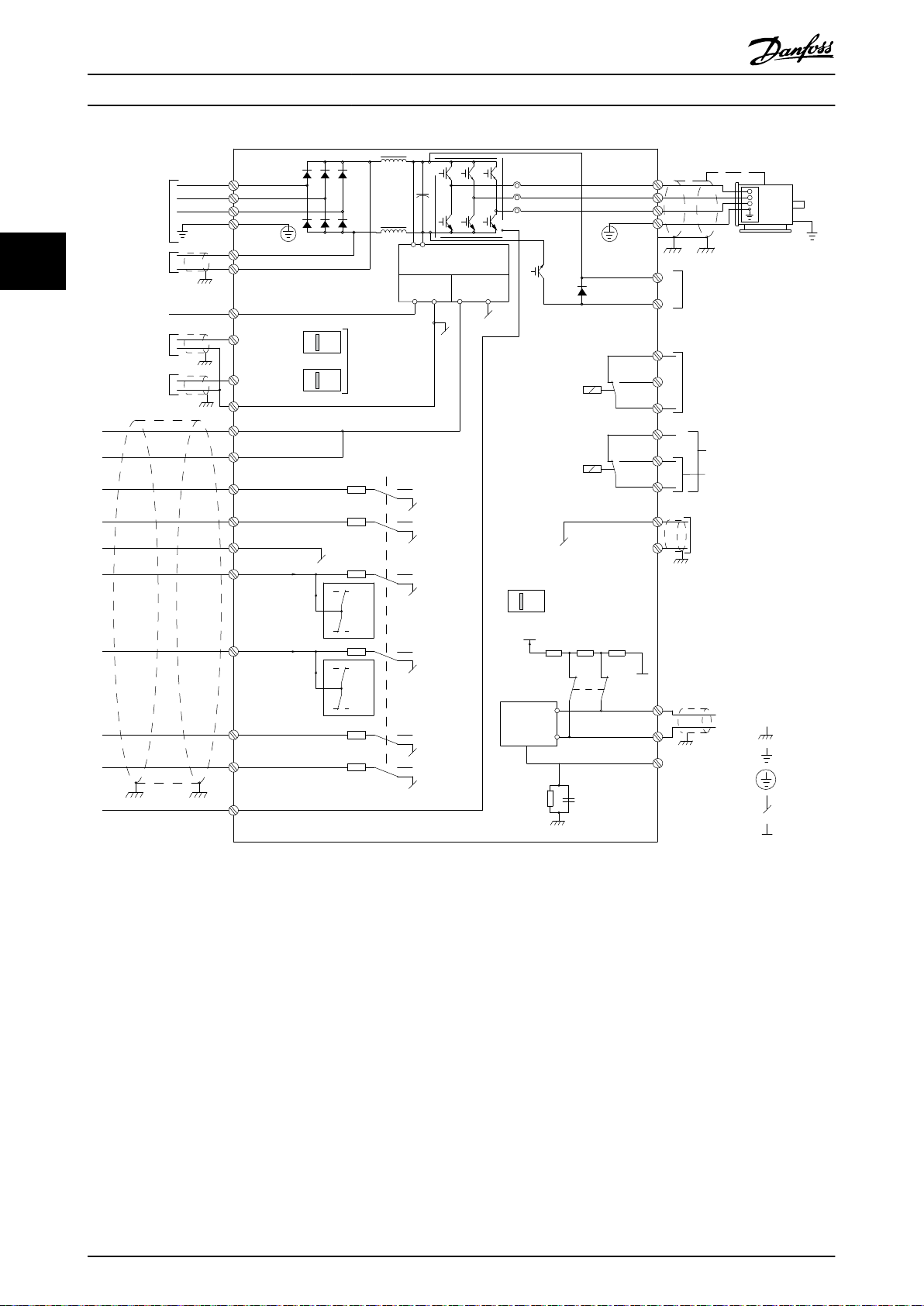
Illustration 3.23 Interconnect Diagram
A=Analog, D=Digital
*Terminal 37 (optional) is used for Safe Torque Off. For Safe Torque Off installation instructions, refer to the VLT® Frequency
Converters - Safe Torque Off Operating Instructions.
**Do not connect cable screen.
26 Danfoss A/S © Rev. 05/2014 All rights reserved. MG16J202
Page 29
Motor
Line Power
Stop
Start
Speed
Control
130BX370.10
Installation Operating Instructions
For safety, comply with the following requirements:
Electronic controls equipment is connected to
•
hazardous mains voltage. Take extreme to protect
against electrical hazards when applying power
to the unit.
Run motor cables from multiple frequency
•
converters separately. Induced voltage from
output motor cables run together can charge
equipment capacitors, even with the equipment
turned off and locked out.
Field wiring terminals are not intended to receive
•
a conductor one size larger.
Overload and equipment protection
An electronically activated function within the
•
frequency converter provides overload protection
for the motor. The overload calculates the level of
increase to activate timing for the trip (controller
output stop) function. The higher the current
draw, the quicker the trip response. The overload
provides Class 20 motor protection. See
chapter 9 Warnings and Alarms for details on the
trip function.
Because the motor wiring carries high frequency
•
current, it is important that wiring for mains,
motor power, and control are run separately. Use
metallic conduit or separated shielded wire. See
Illustration 3.24. Failure to isolate power, motor,
and control wiring could result in less than
optimum equipment performance.
All frequency converters must be provided with
•
short-circuit and overcurrent protection. Input
fusing is required to provide this protection, see
Illustration 3.25. If not factory supplied, fuses must
be provided by the installer as part of installation.
See maximum fuse ratings in
chapter 11.3.1 Protection.
3 3
Illustration 3.24 Example of Proper Electrical Installation using
Conduit
MG16J202 Danfoss A/S © Rev. 05/2014 All rights reserved. 27
Page 30
L1
L1L2L2L3L3
2
91 92 93
1
130BB460.11
Installation Operating Instructions
established, see
(>3.5 mA).
A dedicated ground wire is required for input
•
power, motor power, and control wiring.
Use the clamps provided with the equipment for
•
33
1 Fuses
2 Ground
Illustration 3.25 Frequency Converter Fuses
Wire Type and Ratings
All wiring must comply with local and national
•
regulations regarding cross-section and ambient
temperature requirements.
Danfoss recommends that all power connections
•
are made with a minimum 75 °C rated copper
wire.
Grounding Requirements
3.4.2
WARNING
GROUNDING HAZARD
For operator safety, it is important to ground
•
the frequency converter properly in accordance
with national and local electrical codes as well
as instructions contained within this document.
Do not use conduit connected to the frequency
•
converter as a replacement for proper
grounding.
Ground currents are higher than 3.5 mA.
•
Failure to ground the frequency converter properly could
result in death or serious injury.
3.4.2.1
Follow national and local codes regarding protective
earthing of equipment with a leakage current >3.5 mA.
Frequency converter technology implies high frequency
switching at high power. This generates a leakage current
in the ground connection. A fault current in the frequency
converter at the output power terminals might contain a
DC component, which can charge the filter capacitors and
cause a transient ground current. The ground leakage
current depends on various system configurations
including RFI filtering, screened motor cables, and
frequency converter power.
EN/IEC61800-5-1 (Power Drive System Product Standard)
requires special care if the leakage current exceeds 3.5 mA.
Grounding must be reinforced in one of the following
ways:
See EN 60364-5-54 § 543.7 for further information.
proper ground connections.
Do not ground one frequency converter to
•
another in a daisy-chain fashion.
Keep the ground wire connections as short as
•
possible.
Use high-strand wire to reduce electrical noise.
•
Follow motor manufacturer wiring requirements.
•
Leakage Current (>3.5 mA)
Ground wire of at least 10 mm
•
2 separate ground wires both complying with the
•
dimensioning rules
chapter 3.4.2.1 Leakage Current
2
NOTICE
It is the responsibility of the user or certified electrical
installer to ensure correct grounding of the equipment in
accordance with national and local electrical codes and
standards.
Follow all local and national electrical codes to
•
ground electrical equipment properly.
Proper protective earthing for equipment with
•
ground currents higher than 3.5 mA must be
28 Danfoss A/S © Rev. 05/2014 All rights reserved. MG16J202
Page 31

130BC303.10
130BC304.10
Installation Operating Instructions
3.4.2.2 Grounding
The frequency converter can be grounded using conduit or
shielded cable. For grounding of the power connections,
use the dedicated grounding points as shown in
Illustration 3.26 to Illustration 3.28.
3 3
Illustration 3.26 Grounding Points for IP20 (Chassis) Enclosures
Illustration 3.27 Grounding for IP21/54 Enclosures.
MG16J202 Danfoss A/S © Rev. 05/2014 All rights reserved. 29
Page 32

176FA259.11
:ASTENER TORQUE: MM8 9.6 Nm (7FT-LB)
ASTENER TORQUE: M10 19 Nm (14FT-LB)
S/L2 92
T/L3 93
R/L1 91
W/T3 98
1
Installation Operating Instructions
33
1 Ground terminals
Illustration 3.28 Position of Ground Terminals IP00, Enclosure
Type E
30 Danfoss A/S © Rev. 05/2014 All rights reserved. MG16J202
Page 33

130BC521.10
205
[8.1]
138
[5.4]
274
[10.8]
27
[1.0]
137
[5.4]
1
2
130BC524.11
196
[7.7]
145
[5.7]
27
[1.0]
185
[7.3]
1
2
369
[14.5]
111
[4.4]
224
[8.8]
242
[9.5]
121
[4.8]
43
[1.7]
1
2
130BC550.11
Installation Operating Instructions
3.4.3 Gland/Conduit Entry - IP21 (NEMA 1)
and IP54 (NEMA 12)
Cables are connected through the gland plate from the
bottom. Remove the plate and plan where to place the
entry for the glands or conduits. Illustration 3.29 to
Illustration 3.33 show the cable entry points viewed from
the bottom of various frequency converters.
NOTICE
Fit the gland plate to the frequency converter to ensure
the specified protection degree.
3 3
Mains side
1
2 Motor side
Illustration 3.30 D2h, Bottom View
1 Mains side
2 Motor side
Illustration 3.29 D1h, Bottom View
Mains side
1
2 Motor side
Illustration 3.31 D5h & D6h, Bottom View
MG16J202 Danfoss A/S © Rev. 05/2014 All rights reserved. 31
Page 34

130BC552.11
222
[8.7]
115
[4.5]
337
[13.3]
169
[6.6]
43
[1.7]
-A-
1
2
2
1
176FA289.12
35
350
202.8
98.6
130.0
62.5
Installation Operating Instructions
Motor Connection
3.4.4
WARNING
INDUCED VOLTAGE
Induced voltage from output motor cables run together
33
1 Mains side
2 Motor side
Illustration 3.32 D7h & D8h, Bottom View
can charge equipment capacitors even with the
equipment turned off and locked out.
Run output motor cables from multiple
•
frequency converters separately.
Failure to run output motor cables separately could
result in death or serious injury.
For maximum cable sizes, see chapter 11.1 Power-
•
dependent Specifications.
Comply with local and national electrical codes
•
for cable sizes.
Gland plates are provided at the base of IP21/54
•
and higher (NEMA 1/12) units.
Do not install power factor correction capacitors
•
between the frequency converter and the motor.
Do not wire a starting or pole-changing device
•
between the frequency converter and the motor.
Connect the 3-phase motor wiring to terminals
•
96 (U), 97 (V), and 98 (W).
Ground the cable in accordance with the
•
instructions provided.
Torque terminals in accordance with the
•
information provided in chapter 11.3.4 Connection
Tightening Torques.
Follow motor manufacturer wiring requirements.
•
Mains side
1
2 Motor side
Illustration 3.33 E1, Bottom View
32 Danfoss A/S © Rev. 05/2014 All rights reserved. MG16J202
Page 35

A
A
B
B
33
1.3[ ]
0
0.0[ ]
62
2.4[ ]
101
4.0[ ]
140
5.5[ ]
163
6.4[ ]
185
7.3[ ]
224
8.8[ ]
263
10.4[ ]
293
11.5[ ]
GROUND 88
3.5[ ]
0
0.0[ ]
200
7.9[ ]
94
3.7[ ]
244
9.6[ ]
0
0.0[ ]
272
10.7[ ]
0
0.0[ ]
S
U
W
R T V
3X M8x20 STUD
WITH NUT
SECTION A-A
MAINS TERMINALS
MAINS TERMINAL
SECTION B-B
MOTOR TERMINALS
MOTOR
TERMINAL
130BC305.10
B
B
A
A
254.7
10[ ]
0.0
0[ ]
GROUND 143.4
6[ ]
0.0
0[ ]
GROUND 168.4
7[ ]
331.2
13[ ]
211.1
8[ ]
GROUND168.4
7[ ]
GROUND143.4
6[ ]
42.4
2[ ]
0.0
0[ ]
68.1
3[ ]
125.8
5[ ]
183.5
7[ ]
245.8
10[ ]
299.8
12[ ]
353.8
14[ ]
377.6
15[ ]
284.2
11[ ]
0.0
0[ ]
R
S
T
U
V
W
4X M10x20 STUD
WITH NUT
SECTION B-B
MOTOR TERMINALS AND
BRAKE TERMINALS
MOTOR TERMINAL
SECTION A-A
MAINS TERMINALS
MAINS TERMINAL
130BC332.10
Installation Operating Instructions
3.4.4.1 Terminal Locations: D1h-D4h
3 3
Illustration 3.34 Terminal Locations D1h
Illustration 3.35 Terminal Locations D2h
MG16J202 Danfoss A/S © Rev. 05/2014 All rights reserved. 33
Page 36

A
A
B
B
83
3.3[ ]
0
0.0[ ]
188
7.4[ ]
244
9.6[ ]
0
0.0[ ]
290
11.4[ ]
272
10.7[ ]
0
0.0[ ]
22
0.9[ ]
0
0.0[ ]
62
2.4[ ]
101
4.0[ ]
145
5.7[ ]
184
7.2[ ]
223
8.8[ ]
152
6.0[ ]
217
8.5[ ]
292
11.5[ ]
R
S
T
U
V
W
BRAKE
SECTION A-A
MAINS TERMINALS
MAINS
TERMINAL
SECTION B-B
MOTOR TERMINALS AND
BRAKE TERMINALS
MOTOR TERMINAL
BRAKE
TERMINAL
130BC302.10
A
A
B
B
33
1.3[ ]
0
0.0[ ]
91
3.6[ ]
149
5.8[ ]
211
8.3[ ]
265
10.4[ ]
319
12.6[ ]
200
7.9[ ]
0
0.0[ ]
319
12.6[ ]
376
14.8[ ]
293
11.5[ ]
255
10.0[ ]
0
0.0[ ]
306
12.1[ ]
284
11.2[ ]
0
0.0[ ]
236.8
9[ ]
R
S
T
U
V
W
BRAKE
TERMINALS
SECTION A-A
MAINS TERMINALS
MAINS TERMINAL
SECTION B-B
MOTOR TERMINALS AND
BRAKE TERMINALS
TERMINAL
BRAKE / REGEN
MOTOR TERMINAL
130BC333.10
Installation Operating Instructions
33
Illustration 3.36 Terminal Locations D3h
Illustration 3.37 Terminal Locations D4h
34 Danfoss A/S © Rev. 05/2014 All rights reserved. MG16J202
Page 37

B
B
A
A
45
1.8[ ]
0
0[ ]
46
1.8[ ]
99
3.9[ ]
153
6[ ]
146
5.8[ ]
182
7.2[ ]
193
7.6[ ]
249
9.8[ ]
221
8.7[ ]
260
10.2[ ]
118
4.6[ ]
0
0[ ]
148
5.8[ ]
221
8.7[ ]
90
3.6[ ]
196
7.7[ ]
227
9[ ]
113
4.4[ ]
0
0[ ]
206
8.1[ ]
A-A
R
S
T
U
V
W
B-B
130BC535.11
1
2
3
4
Installation Operating Instructions
3.4.4.2 Terminal Locations: D5h-D8h
3 3
1 Mains terminals
2 Brake terminals
3 Motor terminals
4 Ground terminals
Illustration 3.38 Terminal Locations, D5h with Disconnect Option
MG16J202 Danfoss A/S © Rev. 05/2014 All rights reserved. 35
Page 38

33
1.3[ ]
0
0[ ]
62
2.4[ ]
101
4[ ]
140
5.5[ ]
163
6.4[ ]
185
7.3[ ]
191
7.5[ ]
224
8.8[ ]
256
10.1[ ]
263
10.4[ ]
293
11.5[ ]
511
20.1[ ]
0
0[ ]
517
20.4[ ]
623
24.5[ ]
727
28.6[ ]
246
9.7[ ]
0
0[ ]
293
11.5[ ]
274
10.8[ ]
0
0[ ]
R
S
T
U
V
W
B-B
A-A
3
4
130BC536.11
1
2
Installation Operating Instructions
33
1 Mains terminals
2 Brake terminals
3 Motor terminals
4 Ground terminals
Illustration 3.39 Terminal Locations, D5h with Brake Option
36 Danfoss A/S © Rev. 05/2014 All rights reserved. MG16J202
Page 39

B
B
A
A
0
0.0[ ]
96
3.8[ ]
195
7.7[ ]
227
8.9[ ]
123
4.8[ ]
153
6.0[ ]
458
18.0[ ]
0
0.0[ ]
46
1.8[ ]
50
2.0[ ]
99
3.9[ ]
147
5.8[ ]
182
7.2[ ]
193
7.6[ ]
221
8.7[ ]
249
9.8[ ]
260
10.2[ ]
146
5.8[ ]
0
0.0[ ]
286
11.2[ ]
0
0.0[
113
4.4[ ]
]
206
8.1[ ]
B-B
A-A
R
S
T
U
V
W
130BC537.12
1
2
3
4
5
Installation Operating Instructions
3 3
1 Mains terminals
2 TB6 terminal block for contactor
3 Brake terminals
4 Motor terminals
5 Ground terminals
Illustration 3.40 Terminal Locations, D6h with Contactor Option
MG16J202 Danfoss A/S © Rev. 05/2014 All rights reserved. 37
Page 40

A
A
99
3.9[ ]
153
6.0[ ]
0
0.0[ ]
225
8.9[ ]
45
1.8[ ]
0
0.0[ ]
286
11.2[ ]
0
0.0[ ]
R
S
T
A-A
130BC538.12
1
2
3
4
5
Installation Operating Instructions
33
1 Brake terminals
2 TB6 terminal block for contactor
3 Motor terminals
4 Ground terminals
5 Mains terminals
Illustration 3.41 Terminal Locations, D6h with Contactor and Disconnect Options
38 Danfoss A/S © Rev. 05/2014 All rights reserved. MG16J202
Page 41

130BC542.11
B
BAA
372
14.7[ ]
412
16.2[ ]
395
15.6[ ]
515
20.3[ ]
0
0[ ]
66
2.6[ ]
95
3.7[ ]
131
5.1[ ]
151
5.9[ ]
195.5
8[ ]
238
9.4[ ]
292
11.5[ ]
346
13.6[ ]
49
1.9[ ]
198
7.8[ ]
368
14.5[ ]
545
21.4[ ]
0
0[ ]
119
4.7[ ]
276
10.9[ ]
0
0[ ]
B-B
A-A
R
S
T
U
V
W
1
2
3
4
Installation Operating Instructions
3 3
1 Mains terminals
2 Motor terminals
3 Ground terminals
4 Brake terminals
Illustration 3.42 Terminal Locations, D7h with Disconnect Option
MG16J202 Danfoss A/S © Rev. 05/2014 All rights reserved. 39
Page 42

130BC543.11
B
B
A
A
0
0[ ]
66
2.6[ ]
123
4.9[ ]
181
7.1[ ]
243
9.6[ ]
269
10.6[ ]
297
11.7[ ]
325
12.8[ ]
351
13.8[ ]
40
1.6[ ]
0
0[ ]
1009
39.7[ ]
1034
40.7[ ]
1082
42.6[ ]
1202
47.3[ ]
1260
49.6[ ]
375
14.8[ ]
290
11.4[ ]
0
0[ ]
257
10.1[ ]
309
12.1[ ]
0
0[ ]
B-B
A-A
R
S
T
U
V
W
1
2
3
4
Installation Operating Instructions
33
1 Mains terminals
2 Brake terminals
3 Motor terminals
4 Ground terminals
Illustration 3.43 Terminal Locations, D7h with Brake Option
40 Danfoss A/S © Rev. 05/2014 All rights reserved. MG16J202
Page 43

A
A
B
B
69
2.7[ ]
0
0[ ]
123
4.9[ ]
177
7[ ]
238
9.4[ ]
292
11.5[ ]
346
13.6[ ]
49
1.9[ ]
378
14.9[ ]
198
7.8[ ]
378
14.9[ ]
0
0[ ]
418
16.5[ ]
898
35.3[ ]
401
15.8[ ]
521
20.5[ ]
95
3.7[ ]
151
5.9[ ]
119
4.7[ ]
0
0[ ]
252
9.9[ ]
127
5[ ]
0
0[ ]
A-A
B-B
R
S
T
U
V
W
130BC544.12
1
2
3
4
5
Installation Operating Instructions
3 3
1 TB6 terminal block for contactor 4 Brake terminals
2 Motor terminals 5 Mains terminals
3 Ground terminals
Illustration 3.44 Terminal Locations, D8h with Contactor Option
MG16J202 Danfoss A/S © Rev. 05/2014 All rights reserved. 41
Page 44

C
C
567
22.3[ ]
0
0[ ]
58
2.3[ ]
0
0[ ]
123
4.9[ ]
188
7.4[ ]
246
9.7[ ]
0
0[ ]
C-C
130BC545.12
R
S
T
1
2
3
4
5
Installation
Operating Instructions
33
1 TB6 terminal block for contactor 4 Motor terminals
2 Mains terminals 5 Ground terminals
3 Brake terminals
Illustration 3.45 Terminal Locations, D8h with Contactor and Disconnect Options
42 Danfoss A/S © Rev. 05/2014 All rights reserved. MG16J202
Page 45

176FA278.10
0[0.0]
0[0.0]
600[23.6]
525[20.7]
412[16.2]
300[11.8]
188[7.4]
75[3.0]
B
492[19.4]
323[12.7]
195[7.7]
0[0.0]
155[6.1]
193[7.6]
280[11.0]
371[14.6]
409[16.1]
Installation Operating Instructions
3.4.4.3 Terminal Locations: E1-E2
Terminal Locations - E1
Consider the following position of the terminals when designing the cable access.
3 3
Illustration 3.46 IP21 (NEMA 1) and IP54 (NEMA 12) Enclosure Power Connection Positions
MG16J202 Danfoss A/S © Rev. 05/2014 All rights reserved. 43
Page 46

176FA272.10
0[0.0]
55[2.2]
91[3.6]
139[5.5]
175[6.9]
0[0.0]
453[17.8]
B
A A A A
-R 81
9
19 Nm [14 FTa
Installation Operating Instructions
33
Illustration 3.47 IP21 (NEMA 1) and IP54 (NEMA 12) Enclosure
Power Connection Positions (Detail B)
44 Danfoss A/S © Rev. 05/2014 All rights reserved. MG16J202
Page 47

E
F
B
C
D
0 0.0[ ]
51 2.0[ ]
226 8.9[ ]
266 10.5[ ]
441 17.4[ ]
0 0.0[ ]
28 1.1[ ]
167 6.6[ ]
195 7.7[ ]
A
0 0.0[ ]
176FA279.11
Installation Operating Instructions
3 3
Illustration 3.48 IP21 (NEMA 1) and IP54 (NEMA 12) Enclosure Power Connection Position of Disconnect Switch
Enclosure
types
E1
IP54/IP21 UL AND NEMA1/NEMA12 A B C D E F
Unit type Dimensions [mm]/(inch)
450-630 KW (690 V) 396 (15.6) 267 (10.5) 332 (13.1) 397 (15.6) 528 (20.8) N/A
355-450 kW (400 V) 408 (16.1) 246 (9.7) 326 (12.8) 406 (16.0) 419 (16.5) 459 (18.1)
Table 3.5 Dimensions for Disconnect Terminal
MG16J202 Danfoss A/S © Rev. 05/2014 All rights reserved. 45
Page 48

176FA280.10
585[23.0]
518[20.4]
405[15.9]
68[2.7]
0[0.0]
186[7.3]
0[0.0]
0[0.0]
181[7.1]
293[11.5]
409[16.1]
371[14.6]
280[11.0]
192[7.6]
154[6.1]
17[0.7]
A
R/L1 91
9
S/L2 92
U/T1 96 V/T2 97
T/L3 93
W/T3 98
FASTENER TORQUE M8 9.6 Nm (7 FT-LB) FASTENER TORQUE M8 9.6 Nm (7 FT-LB)
176FA282.10
0(0.0)
47(1.9)
83(3.3)
131(5.2)
167(6.6)
0(0.0)
147(5.8)
A A A A
019Nm (14 F)
9
A
R 81
Installation Operating Instructions
Terminal locations - enclosure type E2
Consider the following position of the terminals when designing the cable access.
33
Illustration 3.49 IP00 Enclosure Power Connection Positions
Illustration 3.50 IP00 Enclosure Power Connection Positions
46 Danfoss A/S © Rev. 05/2014 All rights reserved. MG16J202
Page 49

E
0
0.0[ ]
F
B
0 0.0[ ]
C
D
A
0 0.0[ ]
176FA281.11
Installation Operating Instructions
3 3
Illustration 3.51 IP00 Enclosure Power Connections Positions of Disconnect Switch
NOTICE
Power connections can be made to positions A or B
Enclosure
type
E2
Table 3.6 Dimensions for Disconnect Terminal
3.4.5
250/315 kW (400 V) AND 355/450-500/630
315/355-400/450 kW (400 V) 408 (16.1) 239 (9.4) 319 (12.5) 399 (15.7) 113 (4.4) 153 (6.0)
Motor Cable
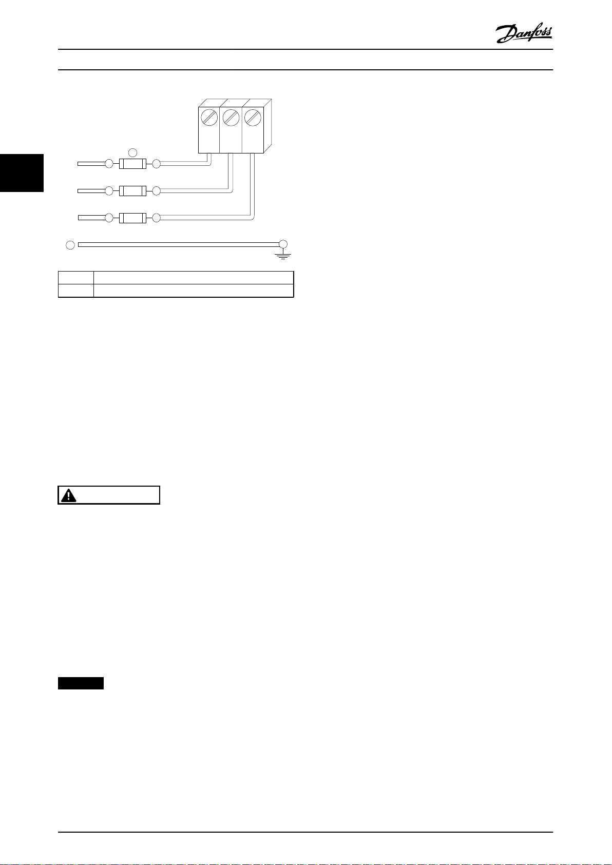
Connect the motor to terminals U/T1/96, V/T2/97, W/T3/98.
Ground to terminal 99. All types of 3-phase asynchronous
standard motors can be used with a frequency converter
unit. The factory setting is for clockwise rotation with the
frequency converter output connected as follows:
Terminal no. Function
96, 97, 98, Mains U/T1, V/T2, W/T3
99 Ground
Unit type Dimensions [mm]/(inch)
IPOO/CHASSIS A B C D E F
KW (690 V)
396 (15.6) 268 (10.6) 333 (13.1) 398 (15.7) 221 (8.7) N/A
Table 3.7 Terminals for Motor Cable Connection
MG16J202 Danfoss A/S © Rev. 05/2014 All rights reserved. 47
Page 50

175HA036.11
U1V
1
W
1
96 97 98
FC
Motor
U
2V2
W
2
U1V
1
W
1
96 97 98
FC
Motor
U
2V2
W
2
130BC254.10
2
1
Installation Operating Instructions
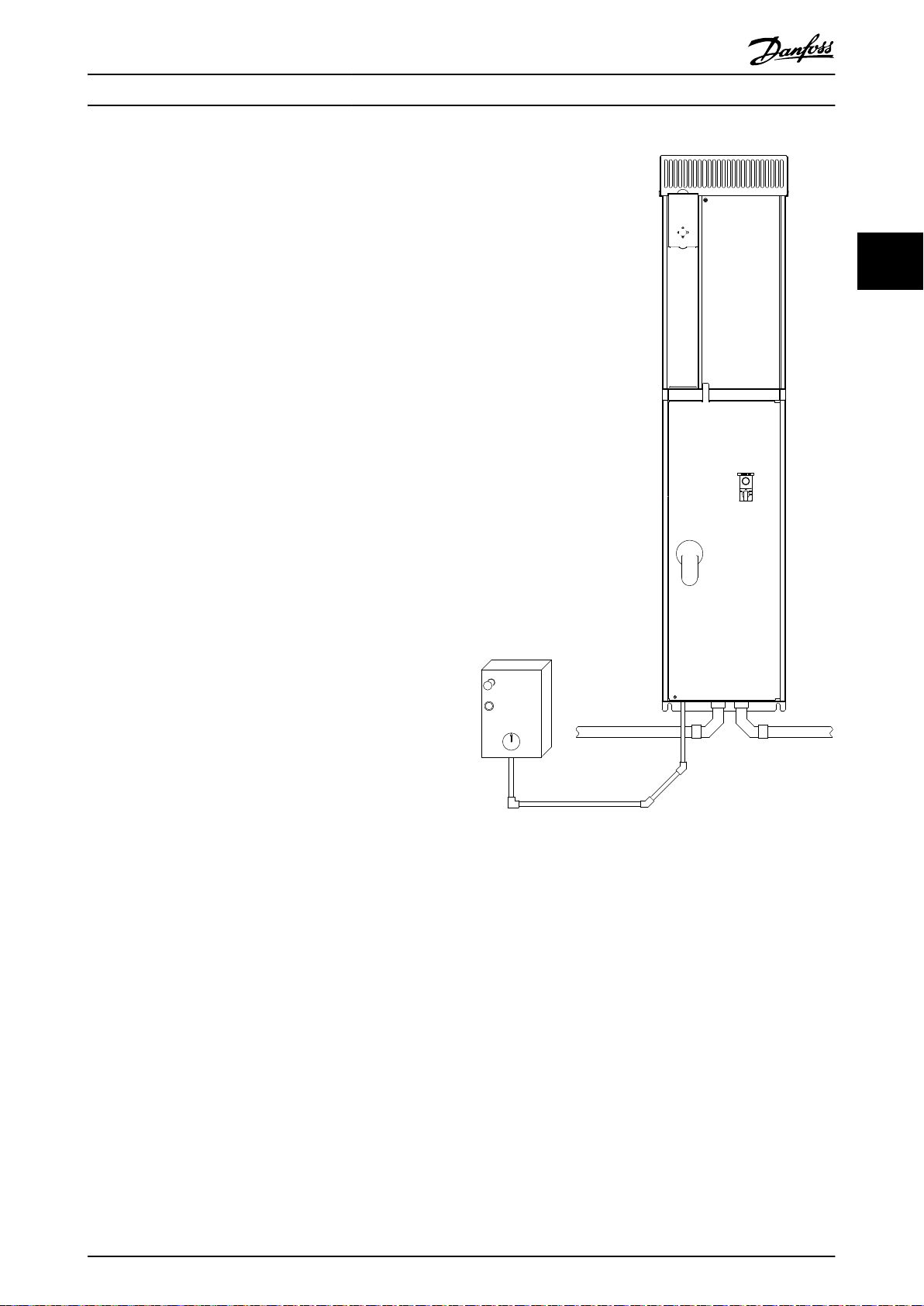
3.4.6 Motor Rotation Check
The direction of rotation can be changed by switching 2
phases in the motor cable, or by changing the setting of
4-10 Motor Speed Direction.
33
Terminal U/T1/96 connected
•
to U-phase
Terminal V/T2/97 connected
•
to V-phase
Terminal W/T3/98
•
connected to W-phase
Table 3.8 Wiring for Changing Motor Direction
A motor rotation check can be performed using 1-28 Motor
Rotation Check and following the steps shown in the
display.
AC Mains Connection
3.4.7
All frequency converters may be used with an
•
isolated input source as well as with ground
reference power lines. When supplied from an
1
Mains connection
2 Motor connection
isolated mains source (IT mains or floating delta)
or TT/TN-S mains with a grounded leg (grounded
Illustration 3.52 Connecting to AC Mains
delta), set 14-50 RFI Filter to [0] Off. When off, the
internal RFI filter capacitors between the chassis
and the intermediate circuit are isolated. Isolating
the capacitors prevents damage to the
intermediate circuit and reduces ground capacity
currents in accordance with IEC 61800-3.
Size wiring is based upon the input current of the
•
frequency converter.
Comply with local and national electrical codes
•
for cable sizes.
1. Ground the cable in accordance with the
instructions provided.
2. Connect 3-phase AC input power wiring to
terminals L1, L2, and L3 (see Illustration 3.52).
48 Danfoss A/S © Rev. 05/2014 All rights reserved. MG16J202
Page 51

175ZT975.10
Installation Operating Instructions
3.4.8 Shielding against Electrical Noise
To ensure best EMC performance, mount the EMC metal
cover before mounting the mains power cable.
NOTICE
The EMC metal cover is only included in units with an
RFI filter.
Illustration 3.53 Mounting of EMC Shield.
3.5.2
Using Screened Control Cables
Danfoss recommends braided screened/armoured cables to
optimise EMC immunity of the control cables and the EMC
emission from the motor cables.
The ability of a cable to reduce the incoming and
outgoing radiation of electric noise depends on the
transfer impedance (ZT). The screen of a cable is normally
designed to reduce the transfer of electric noise; however,
a screen with a lower transfer impedance (ZT) value is
more effective than a screen with a higher transfer
impedance (ZT).
Transfer impedance (ZT) is rarely stated by cable manufacturers, but it is often possible to estimate transfer
impedance (ZT) by assessing the physical design of the
cable.
Transfer impedance (ZT) can be assessed on the basis of
the following factors:
The conductibility of the screen material.
•
The contact resistance between the individual
•
screen conductors.
The screen coverage, i.e. the physical area of the
•
cable covered by the screen - often stated as a
percentage value.
Screen type, i.e. braided or twisted pattern.
•
3 3
3.5 Control Wiring Connection
Isolate control wiring from high power
•
components in the frequency converter.
If the frequency converter is connected to a
•
thermistor for PELV isolation, optional thermistor
control wiring must be reinforced/double
insulated. A 24 V DC supply voltage is
recommended.
Access
3.5.1
All terminals to the control cables are located underneath
the LCP on the inside of the frequency converter. To
access, open the door (IP21/54) or remove the front panel
(IP20).
MG16J202 Danfoss A/S © Rev. 05/2014 All rights reserved. 49
Page 52

175ZA166.13
0,01 0,1 1 10 100 MHz
10
10
10
1
10
10
10
10
10
a
b
c
d
e
f
g
The lower the Z the better the cable screening performance
Transfer impedance, Z
t
mOhm/m
1
2
PE
FC
PE
PLC
130BB922.12
PE PE
<10 mm
100nF
FC
PE
PE
PLC
<10 mm
130BB609.12
PE
FC
PE
FC
130BB923.12
PE PE
69
68
61
69
68
61
1
2
<10 mm
PE
FC
PE
FC
130BB924.12
PE PE
69
69
68
68
1
2
<10 mm
Installation Operating Instructions
33
1
Min. 16 mm
2
2 Equalizing cable
Illustration 3.55 Correct Screening
50/60 Hz ground loops
With very long control cables, ground loops may occur. To
eliminate ground loops, connect one end of the screen-toground with a 100 nF capacitor (keeping leads short).
Illustration 3.56 Avoiding Ground Loops
a Aluminium-clad with copper wire
b Twisted copper wire or armoured steel wire cable
c Single-layer braided copper wire with varying percentage
screen coverage (this is the typical Danfoss reference
cable).
d Double-layer braided copper wire
e Twin layer of braided copper wire with a magnetic,
screened/armoured intermediate layer
f Cable that runs in copper tube or steel tube
g Lead cable with 1.1 mm wall thickness
Avoid EMC noise on serial communication
This terminal is connected to ground via an internal RC
link. Use twisted-pair cables to reduce interference
between conductors. The recommended method is shown
below:
Illustration 3.54 Cable Screening Performance
Grounding of Screened Control
3.5.3
Cables
Correct screening
The preferred method in most cases is to secure control
and serial communication cables with screening clamps
provided at both ends to ensure best possible high
frequency cable contact. If the ground potential between
the frequency converter and the PLC is different, electric
noise may occur that disturbs the entire system. Solve this
problem by fitting an equalizing cable next to the control
cable. Minimum cable cross section: 16 mm2.
50 Danfoss A/S © Rev. 05/2014 All rights reserved. MG16J202
1
Min. 16 mm
2
2 Equalizing cable
Illustration 3.57 Avoiding EMC Noise
Alternatively, the connection to terminal 61 can be
omitted:
1
Min. 16 mm
2
2 Equalizing cable
Illustration 3.58 Screening without Using Terminal 61
Page 53

1
4
2
3
130BA012.12
61
68
69
39
42
50
53
54
55
12
13
18
19
27
29
32
33
20
37
130BT306.10
Installation Operating Instructions
3.5.4 Control Terminal Types
Terminal functions and default settings are summarised in
chapter 3.5.7 Control Terminal Functions.
Some options available for ordering with the unit
•
may provide additional terminals. See the manual
provided with the equipment option.
3.5.5 Wiring to Control Terminals
Terminal plugs can be removed for easy access.
Illustration 3.60 Removal of Control Terminals
Tie down all control wires to the designated control cable
routing as shown in Illustration 3.60. Remember to connect
the shields in a way which ensures optimum electrical
immunity.
3 3
Fieldbus connection
Connections are made to the relevant options on the
control card. For details, see the relevant fieldbus
Illustration 3.59 Control Terminal Locations
instruction. The cable must be placed in the provided path
inside the frequency converter and tied down with other
control wires (see Illustration 3.61).
Connector 1 provides:
•
4 programmable digital input terminals
-
2 additional digital terminals
-
programmable as either input or output
24 V DC terminal supply voltage
-
A common wire for optional customer
-
supplied 24 V DC voltage
Connector 2 terminals (+)68 and (-)69 are for an
•
RS-485 serial communications connection.
Connector 3 provides
•
2 analog inputs
-
1 analog output
-
10 V DC supply voltage
-
Common wires for the inputs and
-
output
Connector 4 is a USB port available for use with
•
the MCT 10 Set-up Software.
Also provided are 2 Form C relay outputs which
•
are located on the power card.
MG16J202 Danfoss A/S © Rev. 05/2014 All rights reserved. 51
Page 54

176FA246.10
U/T1 96
-DC 88
R/L1 91
S/L2 92
T/L3 93
+DC 89
V/T2 97
W/13
130BT310.11
Installation Operating Instructions
The default terminal programming is intended to
•
initiate frequency converter functioning in a
typical operational mode.
3.5.7.1 Terminal 53 and 54 Switches
Analog input terminals 53 and 54 can select
33
•
either voltage (0 to 10 V) or current (0/4-20 mA)
input signals.
Remove power to the frequency converter before
•
changing switch positions.
Set switches A53 and A54 to select the signal
•
type. U selects voltage, I selects current.
The switches are accessible when the LCP has
•
been removed (see Illustration 3.62).
NOTICE
Some option cards available for the unit may cover these
switches and must be removed to change switch
settings. Always remove power to the unit before
removing option cards. Observe the discharge time in
Table 2.1.
Terminal 53 default is for a speed reference signal
•
Illustration 3.61 Control Card Wiring Path for E-enclosures
In the Chassis (IP00) and NEMA 1 units, it is also possible
to connect the fieldbus from the top of the unit. On the
NEMA 1 unit, a cover plate must be removed.
Kit number for fieldbus top connection: 176F1742
in open loop, which is set in 16-61 Terminal 53
Switch Setting
Terminal 54 default is for a feedback signal in
•
closed loop, which is set in 16-63 Terminal 54
Switch Setting
Safe Torque Off (STO)
3.5.6
Safe Torque Off is an option. To run Safe Torque Off,
additional wiring for the frequency converter is required.
Refer to VLT® Frequency Converters Safe Torque Off
Operating Instructions for further information.
Control Terminal Functions
3.5.7
Frequency converter functions are commanded by
receiving control input signals.
Each terminal must be programmed for the
•
function it is supporting in the parameters
associated with that terminal. See
chapter 6 Programming and chapter 7 Application
Examples for terminals and associated parameters.
It is important to confirm that the control
•
terminal is programmed for the correct function.
See chapter 6 Programming for details on
accessing parameters and programming.
Illustration 3.62 Location of Terminals 53 and 54 Switches and
Bus Termination Switch
52 Danfoss A/S © Rev. 05/2014 All rights reserved. MG16J202
Page 55

Installation Operating Instructions
3.6 Serial Communication
3.7.2
Mains Shield
RS-485 is a 2-wire bus interface compatible with multi-drop
network topology, i.e. nodes can be connected as a bus, or
via drop cables from a common trunk line. A total of 32
nodes can be connected to 1 network segment.
Repeaters divide network segments. Each repeater
functions as a node within the segment it is installed in.
Each node connected within a given network must have a
unique node address across all segments.
Terminate each segment at both ends, using
•
either the termination switch (S801) of the
frequency converter or a biased termination
resistor network.
Always use screened twisted pair (STP) cable for
•
bus cabling.
Always follow good common installation practice.
•
Low-impedance ground connection of the screen at every
node is important, including at high frequencies.
Connect a large surface of the screen to ground,
•
for example with a cable clamp or a conductive
cable gland. It may be necessary to apply
potential-equalizing cables to maintain the same
ground potential throughout the network. Particularly in installations with long cables.
To prevent impedance mismatch, always use the
•
same type of cable throughout the entire
network.
When connecting a motor to the frequency
•
converter, always use screened motor cable.
The mains shield is a Lexan cover installed inside the
enclosure to provide protection according to BGV A3
(former VBG-4) accident-prevention requirements.
NOTICE
Mains shield is only available for IP21/IP54 (NEMA 1/
NEMA 12).
3 3
Cable
Impedance
Max. cable length [m] 1200 (including drop lines)
Table 3.9 Cable Information
3.7
Optional Equipment
Screened twisted pair (STP)
120 Ω
500 station-to-station
3.7.1 Anti-condensation Heater
An anti-condensation heater can be installed inside the
frequency converter to prevent condensation from forming
inside the enclosure when the unit is turned off. The
heater is controlled by customer-supplied 230 V AC. For
best results, only operate the heater when the unit is not
running.
MG16J202 Danfoss A/S © Rev. 05/2014 All rights reserved. 53
Page 56

Start-up and Functional Tes... Operating Instructions
4 Start-up and Functional Testing
4.1 Pre-start
4.1.1 Safety Inspection
WARNING
44
HIGH VOLTAGE
If input and output connections have been connected improperly, there is potential for high voltage on these terminals.
If power leads for multiple motors are improperly run in same conduit, there is potential for leakage current to charge
capacitors within the frequency converter, even when disconnected from mains input.
For initial start-up, make no assumptions about power components.
•
Follow pre-start procedures.
•
Failure to follow pre-start procedures could result in personal injury or damage to equipment.
1. Switch off the Input power to the unit and ensure that it is locked out. Do not rely on the frequency converter
disconnect switches for input power isolation.
2. Verify that there is no voltage on input terminals L1 (91), L2 (92), and L3 (93), phase-to-phase and phase-toground,
3. Verify that there is no voltage on output terminals 96 (U), 97 (V), and 98 (W), phase-to-phase and phase-to-ground.
4. Confirm continuity of the motor by measuring ohm values on U-V (96-97), V-W (97-98), and W-U (98-96).
5. Check for proper grounding of the frequency converter as well as the motor.
6. Inspect the frequency converter for loose connections on terminals.
7. Record the following motor-nameplate data
7a Power
7b Voltage
7c Frequency
7d Full load current
7e Nominal speed.
These values are needed to program the motor nameplate data later.
8. Confirm that the supply voltage matches the voltage of the frequency converter and the motor.
CAUTION
Before applying power to the unit, inspect the entire installation as detailed in Table 4.1. Check mark those items when
completed.
Inspect for Description
Auxiliary equipment
Look for auxiliary equipment, switches, disconnects, or input fuses/circuit breakers on the input
•
power side of the frequency converter or output side to the motor. Ensure that they are ready for
full speed operation.
Check function and installation of any sensors used for feedback to the frequency converter.
•
Remove power factor correction caps on motors, if present.
•
☑
54 Danfoss A/S © Rev. 05/2014 All rights reserved. MG16J202
Page 57

Start-up and Functional Tes... Operating Instructions
Inspect for Description
Cable routing
Control wiring
Cooling clearance
EMC considerations
Environmental considerations
Fusing and circuit
breakers
Grounding
Input and output power
wiring
Panel interior
Switches
Vibration
Use separate metallic conduits for each of the following:
•
-
-
-
Check for broken or damaged wires and loose connections.
•
Check that control wiring is isolated from power and motor wiring for noise immunity.
•
Check the voltage source of the signals, if necessary.
•
Use shielded or twisted pair cable. Ensure that the shield is terminated correctly.
•
Measure that top and bottom clearance is adequate to ensure proper air flow for cooling.
•
Check for proper installation regarding electromagnetic compatibility.
•
See equipment label for the maximum ambient operating temperature limits.
•
Humidity levels must be 5–95%, non-condensing.
•
Check for proper fusing or circuit breakers.
•
Check that all fuses are inserted firmly and in operational condition and that all circuit breakers are
•
in the open position.
The unit requires a ground wire from its chassis to the building ground.
•
Check for good ground connections that are tight and free of oxidation.
•
Grounding to conduit or mounting the back panel to a metal surface is not sufficient.
•
Check for loose connections.
•
Check that motor and mains are in separate conduit or separated screened cables.
•
Inspect that the unit interior is free of debris and corrosion.
•
Ensure that all switch and disconnect settings are in the proper positions.
•
Check that the unit is mounted solidly or that shock mounts are used, as necessary.
•
Check for an unusual amount of vibration.
•
☑
Input power
Motor wiring
Control wiring
4 4
Table 4.1 Start-up Checklist
MG16J202 Danfoss A/S © Rev. 05/2014 All rights reserved. 55
Page 58

130BC951.10
Start-up and Functional Tes...
Operating Instructions
4.2 Applying Power
WARNING
HIGH VOLTAGE
Frequency converters contain high voltage when
connected to AC mains.
Only qualified personnel should perform instal-
•
lation, start-up and maintenance.
44
Failure to comply could result in death or serious injury.
WARNING
UNINTENDED START
When the frequency converter is connected to AC mains,
the motor may start at any time.
Ensure that the frequency converter, motor, and
•
any driven equipment are in operational
readiness.
Failure to comply could result in death, serious injury,
equipment, or property damage.
1. Confirm that the input voltage is balanced within
3%. If not, correct input voltage imbalance before
proceeding. Repeat this procedure after the
voltage correction.
2. Ensure that optional equipment wiring, if present,
matches the installation application.
3. Ensure that all operator devices are in the OFF
position. Panel doors should be closed or cover
mounted.
4. Apply power to the unit. DO NOT start the
frequency converter at this time. For units with a
disconnect switch, turn to the ON position to
apply power to the frequency converter.
NOTICE
If the status line at the bottom of the display reads
AUTO REMOTE COASTING or Alarm 60 External Interlock
is displayed, this indicates that the unit is ready to
operate, but is missing an input signal on terminal 27.
The built-in wizard menu guides the installer through the
set-up of the frequency converter in a clear and structured
manner, and has been constructed with reference to the
industries refrigeration engineers, to ensure that the text
and language is known within that specific business area.
At start-up, the FC 103 asks the user to run the VLT® Drive
Application Guide or to skip it (until it has been run, the
FC 103 asks every time at start-up), thereafter in the event
of power failure, the application guide is accessed via the
Quick Menu screen.
If [Cancel] is pressed, the FC 103 returns to the status
screen. An automatic timer cancels the wizard after 5 min.
of inactivity (no keys pressed). The wizard must be reentered via the Quick Menu when it has been run once.
Answering the questions on the screens takes the user
though a complete set-up for the FC 103. Most standard
refrigeration applications can be set up by using this
application guide. Access advanced features via the menu
structure (Quick Menu or Main Menu) in the frequency
converter.
The FC 103 Wizard covers all standard settings for:
Compressors
•
Single fan and pump
•
Condenser fans
•
These applications are then further expanded to allow
control of the frequency converter via its own internal PID
controllers or from an external control signal.
After completing set-up, re-run the wizard or start the
application
The application guide can be cancelled at any time by
pressing [Back]. The application guide can be re-entered
via the Quick Menu. When re-entering the application
guide, either keep previous changes to the factory set-up
or restore default values.
On power-up, the FC 103 launches an application guide. In
the event of power failure, the application guide is
accessed via the Quick Menu screen.
4.3 Basic Operational Programming
4.3.1 Set-up Wizard
NOTICE
RISK OF EQUIPMENT DAMAGE
Always stop the frequency converter before using the
wizard. Failure to stop the frequency converter may
cause equipment damage.
56 Danfoss A/S © Rev. 05/2014 All rights reserved. MG16J202
Illustration 4.1 Quick Menu Screen
If [Cancel] is pressed, the FC 103 returns to the status
screen. An automatic timer cancels the wizard after 5 min.
of inactivity (no keys pressed). Re-enter the wizard via the
Quick Menu as described in this section.
Page 59

130BC952.10
130BC953.10
130BC954.10
Start-up and Functional Tes...
If [OK] is pressed, the application guide starts with the
following screen:
Illustration 4.2 Start-up of Application Guide
Operating Instructions
NOTICE
Numbering of steps in wizard (e.g. 1/12) can change
depending on choices in the workflow.
This screen automatically changes to the first input screen
of the application guide:
Illustration 4.6 Current and Nominal Speed Set-up
4 4
Illustration 4.7 Min. and Max. Frequency Set-up
Illustration 4.3 Language Selection
Illustration 4.4 Application Selection
Compressor pack set-up
As an example, see screens below for a compressor pack
set-up:
Illustration 4.5 Voltage and Frequency Set-up
Illustration 4.8 Min. Time between 2 Starts
Illustration 4.9 Select with/without Bypass Valve
Illustration 4.10 Select Open Loop or Closed Loop
MG16J202 Danfoss A/S © Rev. 05/2014 All rights reserved. 57
Page 60

Start-up and Functional Tes... Operating Instructions
NOTICE
Internal/closed loop: The FC 103 controls the application
directly using the internal PID control and needs an
input from an external input, such as a temperature or
other sensor, which is wired directly into the frequency
converter and controls from the sensor signal.
External/open loop: The FC 103 takes its control signal
from another controller (such as a pack controller), which
44
gives the frequency converter e.g. 0-10 V, 4-20 mA or FC
103 Lon. The frequency converter changes its speed
depending on this reference signal.
Illustration 4.11 Select Sensor Type
Illustration 4.14 Info: Set Switch Accordingly
Illustration 4.15 Select Unit and Conversion from Pressure
Illustration 4.12 Settings for Sensor
Illustration 4.13 Info: 4-20 mA Feedback Chosen - Connect
Accordingly
Illustration 4.16 Select Fixed or Floating Setpoint
Illustration 4.17 Set Setpoint
Illustration 4.18 Set High/Low Limit for Setpoint
58 Danfoss A/S © Rev. 05/2014 All rights reserved. MG16J202
Page 61

130BC955.10
130BP956.10
130BC957.10
Start-up and Functional Tes...
Illustration 4.19 Set Cut Out/In Value
Illustration 4.20 Select Pack Control Set-up
Operating Instructions
After completing set-up, re-run the wizard or start the
application. Select between the following options:
Re-run wizard
•
Go to main menu
•
Go to status
•
Run AMA - Note this is a reduced AMA if
•
compressor application is selected, and full AMA
if single fan and pump is selected.
If condenser fan is selected in application NO
•
AMA can be run.
Run application - this mode starts the frequency
•
converter in either hand/local mode or via an
external control signal if open loop is selected in
an earlier screen.
4 4
Illustration 4.21 Set Number of Compressors in Pack
Illustration 4.22 Info: Connect Accordingly
Illustration 4.23 Info: Setup Completed
Illustration 4.24 Run Application
The application guide can be cancelled at any time by
pressing [Back]. The application guide can be re-entered
via the Quick Menu:
Illustration 4.25 Quick Menus
When re-entering the application guide, select between
previous changes to the factory set-up or restore default
values.
NOTICE
If the system requirement is to have the internal pack
controller for 3 compressors plus bypass valve
connected, specify FC 103 with the extra relay card (MCB
105) mounted inside the frequency converter.
Programme the bypass valve to operate from one of the
extra relay outputs on the MCB 105 board.
This is needed because the standard relay outputs in the
FC 103 are used to control the compressors in the pack.
MG16J202 Danfoss A/S © Rev. 05/2014 All rights reserved. 59
Page 62

130BP066.10
1107 RPM
0 -
**
Operation/Display
1 -
**
Load/Motor
2 -
**
Brakes
3 -
**
Reference / Ramps
3.84 A 1 (1)
Main menu
0-
**
Operation / Display
0.0%
0-0
*
Basic Settings
0-1
*
Set-up Operations
0-2
*
LCP Display
0-3
*
LCP Custom Readout
0.00A 1(1)
130BP087.10
0-0
*
Basic Settings
0.0%
0-03 Regional Settings
[0] International
0.00A 1(1)
130BP088.10
130BB847.10
Q1 My Personal Menu
Q2 Quick Setup
Q5 Changes Made
Q6 Loggings
13.7% 13.0A 1(1)
Quick Menus
Start-up and Functional Tes...
Operating Instructions
4.3.2 Required Initial Frequency Converter
Programming
NOTICE
If the wizard is run, ignore the following.
Frequency converters require basic operational
programming before running for best performance. This
44
requires entering motor-nameplate data for the motor
being operated and the minimum and maximum motor
speeds. Enter data in accordance with the following
procedure. Parameter settings recommended are intended
for start-up and checkout purposes. Application settings
may vary. See chapter 5 User Interface for detailed
instructions on entering data via the LCP.
Enter data with power ON, but before operating the
frequency converter.
1. Press [Main Menu] twice on the LCP.
2. Press the navigation keys to scroll to parameter
group 0-** Operation/Display and press [OK].
Illustration 4.28 Basic Settings
5.
Press the navigation keys to select [0] Interna-
tional or [1] North America as appropriate and
press [OK]. (This changes the default settings for
a number of basic parameters. See
chapter 6.4 International/North American Default
Parameter Settings for a complete list.)
6. Press [Quick Menu] on the LCP.
7. Press the navigation keys to scroll to parameter
group Q2 Quick Setup and press [OK].
Illustration 4.26 Main Menu
3. Press the navigation keys to scroll to parameter
group 0-0* Basic Settings and press [OK].
Illustration 4.27 Operation/Display
4. Press the navigation keys to scroll to
0-03 Regional Settings and press [OK].
Illustration 4.29 Quick Menus
8. Select the language and press [OK].
9. A jumper wire should be in place between
control terminals 12 and 27. If this is the case,
leave 5-12 Terminal 27 Digital Input at factory
default. Otherwise select No Operation. For
frequency converters with an optional Danfoss
bypass, no jumper wire is required.
10.
Set 3-02 Minimum Reference
11.
Set 3-03 Maximum Reference
12.
Set 3-41 Ramp 1 Ramp Up Time
13.
Set 3-42 Ramp 1 Ramp Down Time
14.
Set 3-13 Reference Site. Linked to Hand/Auto*
Local Remote.
60 Danfoss A/S © Rev. 05/2014 All rights reserved. MG16J202
Page 63

Start-up and Functional Tes...
Operating Instructions
4.4 Automatic Motor Adaptation
Automatic motor adaptation (AMA) is a test procedure,
which measures the electrical characteristics of the motor
to optimise compatibility between the frequency converter
and the motor.
The frequency converter builds a mathematical
•
model of the motor for regulating output motor
current. The procedure also tests the input phase
balance of electrical power. It compares the
motor characteristics with the data entered in
parameters 1-20 to 1-25.
The motor shaft does not turn and no harm is
•
done to the motor while running the AMA.
Some motors may be unable to run the complete
•
version of the test. In that case, select [2] Enable
reduced AMA.
If an output filter is connected to the motor,
•
select Enable reduced AMA.
If warnings or alarms occur, see
•
chapter 9 Warnings and Alarms
Run this procedure on a cold motor for best
•
results.
3. Press [OK].
4.
Scroll to 1-28 Motor Rotation Check.
5. Press [OK].
6.
Scroll to [1] Enable.
The following text appears: Note! Motor may run in wrong
direction.
7. Press [OK].
8. Follow the on-screen instructions.
To change the direction of rotation, remove power to the
frequency converter and wait for the discharge time to
elapse, see Table 2.1. Reverse the connection of any 2 of
the 3 motor cables on the motor or frequency converter
side of the connection.
4.6 Local-control Test
CAUTION
MOTOR START
Ensure that the motor, system and any attached
equipment are ready for start. It is the responsibility of
the user to ensure safe operation under any condition.
Failure to ensure that the motor, system, and any
attached equipment is ready for start could result in
personal injury or equipment damage.
4 4
NOTICE
The AMA algorithm does not work when using PM
motors.
To run AMA
1. Press [Main Menu] to access parameters.
2.
Scroll to parameter group 1-** Load and Motor.
3. Press [OK].
4.
Scroll to parameter group 1-2* Motor Data.
5. Press [OK].
6.
Scroll to 1-29 Automatic Motor Adaptation (AMA).
7. Press [OK].
8.
Select [1] Enable complete AMA.
9. Press [OK].
10. Follow the on-screen instructions.
11. The test runs automatically and indicates when it
is complete.
4.5
Check Motor Rotation
Before running the frequency converter, check the motor
rotation. The motor runs briefly at 5 Hz or the minimum
frequency set in 4-12 Motor Speed Low Limit [Hz].
1. Press [Quick Menu].
2.
Scroll to Q2 Quick Setup.
NOTICE
The [Hand On] key provides a local start command to
the frequency converter. The [Off] key provides the stop
function.
When operating in local mode, [▲] and [▼] increase and
decrease the speed output of the frequency converter.
[◄] and [►] move the display cursor in the numeric
display.
1. Press [Hand On].
2. Accelerate the frequency converter by pressing
[▲] to full speed. Moving the cursor left of the
decimal point provides quicker input changes.
3. Note any acceleration problems.
4. Press [Off].
5. Note any deceleration problems.
If acceleration problems were encountered:
If warnings or alarms occur, see
•
chapter 9 Warnings and Alarms.
Check that motor data is entered correctly.
•
Increase the ramp-up time in 3-41 Ramp 1 Ramp
•
Up Time.
Increase the current limit in 4-18 Current Limit.
•
Increase the torque limit in 4-16 Torque Limit
•
Motor Mode.
MG16J202 Danfoss A/S © Rev. 05/2014 All rights reserved. 61
Page 64

Start-up and Functional Tes...
If deceleration problems were encountered:
If warnings or alarms occur, see
•
chapter 9 Warnings and Alarms.
Check that motor data is entered correctly.
•
Increase the ramp-down time in 3-42 Ramp 1
•
Ramp Down Time.
Enable overvoltage control in 2-17 Over-voltage
44
•
Control.
See chapter 5.1.1 Local Control Panel for resetting the
frequency converter after a trip.
Operating Instructions
NOTICE
Chapter 4.2 Applying Power and chapter 4.3 Basic
Operational Programming conclude the procedures for
applying power to the frequency converter, basic
programming, set-up, and functional testing.
4.7 System Start-up
The procedure in this section requires user-wiring and
application programming to be completed.
Chapter 7 Application Examples is intended to help with
this task. Other aids to application set-up are listed in
chapter 1.2 Additional Resources. The following procedure is
recommended after application set-up by the user is
completed.
CAUTION
MOTOR START
Ensure that the motor, system and any attached
equipment is ready for start. It is the responsibility of the
user to ensure safe operation under any condition.
Failure to do so could result in personal injury or
equipment damage.
1. Press [Auto On].
2. Ensure that the external control functions are
properly wired to the frequency converter and all
programming is completed.
3. Apply an external run command.
4. Adjust the speed reference throughout the speed
range.
5. Remove the external run command.
6. Note any problems.
If warnings or alarms occur, see chapter 9 Warnings and
Alarms.
62 Danfoss A/S © Rev. 05/2014 All rights reserved. MG16J202
Page 65

130BD512.10
Auto
on
Reset
Hand
on
O
Status
Quick
Menu
Main
Menu
Alarm
Log
Back
Cancel
Info
OK
Status
1(1)
0.00 kW
O Remote Stop
0.0Hz
On
Alarm
Warn.
A
0.00 A
0.0 %
B
C
D
2605 kWh
1
2
3
4
5
6
7
8
9
10
11
12
13
14
15
16
17
18 19 20 21
User Interface
5 User Interface
5.1 Local Control Panel
Operating Instructions
5.1.1
LCP Layout
The local control panel (LCP) is the combined display and
keypad on the front of the unit. The LCP is the user
interface to the frequency converter.
The LCP has several user functions.
Start, stop, and control speed when in local
•
control
Display operational data, status, warnings and
•
cautions
Programming frequency converter functions
•
Manually reset the frequency converter after a
•
fault when auto-reset is inactive
An optional numeric LCP (NLCP) is also available. The NLCP
operates in a manner similar to the LCP. See the
Programming Guide, for details on use of the NLCP.
The LCP is divided into 4 functional groups (see
Illustration 5.1).
A. Display area
B. Display menu keys
C. Navigation keys and indicator lights (LEDs)
D. Operation keys and reset
5 5
Illustration 5.1 Local Control Panel (LCP)
MG16J202 Danfoss A/S © Rev. 05/2014 All rights reserved. 63
A. Display Area
The display area is activated when the frequency converter
receives power from mains voltage, a DC bus terminal, or
an external 24 V DC supply.
The information displayed on the LCP can be customised
for user application. Select options in the Quick Menu
Q3-13 Display Settings.
Page 66

User Interface Operating Instructions
Callout Display Parameter number Default setting
1 1.1 0-20 Reference %
2 1.2 0-21 Motor current
3 1.3 0-22 Power [kW]
4 2 0-23 Frequency
5 3 0-24 kWh counter
Table 5.1 Legend to Illustration 5.1, Display Area
B. Display Menu Keys
Menu keys are used for menu access for parameter set-up,
toggling through status display modes during normal
55
operation, and viewing fault log data.
Callout Key Function
6 Status Shows operational information.
7 Quick Menu Allows access to programming
parameters for initial set-up instructions
and many detailed application
instructions.
8 Main Menu Allows access to all programming
parameters.
9 Alarm Log Displays a list of current warnings, the
last 10 alarms, and the maintenance log.
Table 5.2 Legend to Illustration 5.1, Display Menu Keys
C. Navigation Keys and Indicator Lights (LEDs)
Navigation keys are used for programming functions and
moving the display cursor. The navigation keys also
provide speed control in local (hand) operation. There are
also 3 frequency converter status indicator lights in this
area.
Callout Key Function
10 Back Reverts to the previous step or list in the
menu structure.
11 Cancel Cancels the last change or command as
long as the display mode has not
changed.
12 Info Press for a definition of the function being
displayed.
13 Navigation
keys
14 OK Press to access parameter groups or to
Press to move between items in the
menu.
enable a choice.
Callout Indicator Light Function
15 ON Green The ON light activates when the
frequency converter receives
power from mains voltage, a DC
bus terminal, or an external 24 V
supply.
16 WARN Yellow When a warning is issued, the
yellow WARN light comes on
and text appears in the display
area identifying the problem.
17 ALARM Red A fault condition causes the red
alarm light to flash and an alarm
text is displayed.
Table 5.4 Legend to Illustration 5.1, Indicator Lights (LEDs)
D. Operation Keys and Reset
Operation keys are located at the bottom of the LCP.
Callout Key Function
18 Hand On Starts the frequency converter in local
control.
An external stop signal by control
•
input or serial communication
overrides the local hand on.
19 Off Stops the motor but does not remove
power to the frequency converter.
20 Auto On Puts the system in remote operational
mode.
Responds to an external start
•
command by control terminals or
serial communication.
21 Reset Resets the frequency converter manually
after a fault has been cleared.
Table 5.5 Legend to Illustration 5.1, Operation Keys and Reset
NOTICE
The display contrast can be adjusted by pressing [Status]
and [▲]/[▼] keys.
Table 5.3 Legend to Illustration 5.1, Navigation Keys
64 Danfoss A/S © Rev. 05/2014 All rights reserved. MG16J202
Page 67

1.1
2
3
1.3
1.2
130BT831.10
0.0%
Off Remote Stop
1 (1)
0.00 kw0.00 A
0.0Hz
2605kWh
Status
130BP045.10
Status
Quick
Menu
Main
Menu
Alarm
Log
User Interface
Operating Instructions
5.1.2 Setting LCP Display Values
The display area is activated when the frequency converter
receives power from mains voltage, a DC bus terminal, or
an external 24 V DC supply.
The information displayed on the LCP can be customised
for user application.
Each display readout has a parameter associated
•
with it.
Options are selected in the quick menu Q3-13
•
Display Settings.
Display 2 has an alternate larger display option.
•
The frequency converter status at the bottom line
•
of the display is generated automatically and is
not selectable.
Display Parameter number Default setting
1.1 0-20 Reference %
1.2 0-21 Motor current
1.3 0-22 Power [kW]
2 0-23 Frequency
3 0-24 kWh counter
Illustration 5.2 Display Readouts
Display Menu Keys
5.1.3
Menu keys are used for menu access for parameter set-up,
toggling through status display modes during normal
operation, and viewing fault log data.
Illustration 5.3 Menu Keys
Key Function
Status
Quick Menu
Main Menu
Alarm Log
Shows operational information.
In Auto mode, press to toggle between
•
status readout displays.
Press repeatedly to scroll through each
•
status display.
•
Press [Status] plus [▲] or [▼] to adjust the
display brightness.
The symbol in the upper right corner of the
•
display shows the direction of motor
rotation and which set-up is active. This is
not programmable.
Allows access to programming parameters for
initial set-up instructions and many detailed
application instructions.
Press to access Q2 Quick Set-up for
•
sequenced instructions to program the basic
frequency controller set-up.
Follow the sequence of parameters as
•
presented for the function set-up.
Allows access to all programming parameters.
Press twice to access top-level index.
•
Press once to return to the last location
•
accessed.
Press to enter a parameter number for
•
direct access to that parameter.
Displays a list of current warnings, the last 10
alarms, and the maintenance log.
For details about the frequency converter
•
before it entered the alarm mode, select the
alarm number using the navigation keys
and press [OK].
5 5
Table 5.6 Function Description Menu Keys
MG16J202 Danfoss A/S © Rev. 05/2014 All rights reserved. 65
Page 68

130BT117.10
OK
Back
Info
Warn
Alarm
On
Cancel
130BP046.10
Hand
on
O
Auto
on
Reset
User Interface
Operating Instructions
5.1.4 Navigation Keys
Navigation keys are used for programming functions and
5.1.5
Operation Keys
Operation keys are located at the bottom of the LCP.
moving the display cursor. The navigation keys also
provide speed control in local (hand) operation. There are
also 3 frequency converter status indicator lights in this
area.
Illustration 5.5 Operation Keys
55
Illustration 5.4 Navigation Keys
Key Function
Back
Cancel
Info
Navigation
Keys
OK
Table 5.7 Navigation Keys Functions
Light Indicator Function
Green ON The ON light activates when the
Yellow WARN When warning conditions are met,
Red ALARM A fault condition causes the red
Reverts to the previous step or list in the menu
structure.
Cancels the last change or command as long as
the display mode has not changed.
Press for a definition of the function being
displayed.
Press the 4 navigation keys to move between
items in the menu.
Press to access parameter groups or to enable a
choice.
frequency converter receives
power from mains voltage, a DC
bus terminal, or an external 24 V
supply.
the yellow WARN light comes on
and text appears in the display
area identifying the problem.
alarm light to flash and an alarm
text is displayed.
Key Function
Hand On
Off
Auto On
Reset
Table 5.9 Operation Keys Functions
5.2
Back-up and Copying Parameter
Starts the frequency converter in local control.
Use the navigation keys to control frequency
•
converter speed.
An external stop signal by control input or
•
serial communication overrides the local hand
on.
Stops the motor, but does not remove power to
the frequency converter.
Puts the system in remote operational mode.
Responds to an external start command by
•
control terminals or serial communication.
Speed reference is from an external source.
•
Resets the frequency converter manually after a
fault has been cleared.
Settings
Programming data is stored internally in the frequency
converter.
The data can be uploaded into the LCP memory
•
as a storage back up.
Once stored in the LCP, the data can be
•
downloaded back into the frequency converter.
Data can also be downloaded into other
•
frequency converters by connecting the LCP into
those units and downloading the stored settings.
(This is a quick way to program multiple units
with the same settings).
Initialisation of the frequency converter to restore
•
factory default settings does not change data
stored in the LCP memory.
Table 5.8 Indicator Lights Functions
66 Danfoss A/S © Rev. 05/2014 All rights reserved. MG16J202
Page 69

User Interface
Operating Instructions
WARNING
UNINTENDED START
When the frequency converter is connected to AC mains,
or DC power supply, the motor may start at any time.
Unintended start during programming, service or repair
work can result in death, serious injury, or property
damage. The motor can start by means of an external
switch, a serial bus command, an input reference signal
from the LCP, or after a cleared fault condition.
To prevent unintended motor start:
Disconnect the frequency converter from mains.
•
Press [Off/Reset] on the LCP, before
•
programming parameters.
The frequency converter, motor, and any driven
•
equipment must be fully wired and assembled
when the frequency converter is connected to
AC mains, or DC power supply.
Uploading Data to the LCP
5.2.1
1. Press [Off] to stop the motor before uploading or
downloading data.
2.
Go to 0-50 LCP Copy.
3. Press [OK].
4.
Select All to LCP.
5. Press [OK]. A progress bar shows the uploading
process.
6. Press [Hand On] or [Auto On] to return to normal
operation.
Downloading Data from the LCP
5.2.2
Restoring the frequency converter parameter settings back
to default values is done by initialisation of the frequency
converter. Initialisation can be carried out via
14-22 Operation Mode or manually.
Initialisation using 14-22 Operation Mode does not
•
change frequency converter data such as
operating hours, serial communication selections,
personal menu settings, fault log, alarm log, and
other monitoring functions.
Using 14-22 Operation Mode is generally
•
recommended.
Manual initialisation erases all motor,
•
programming, localisation, and monitoring data
and restores factory default settings.
Recommended Initialisation
5.3.1
1. Press [Main Menu] twice to access parameters.
2.
Scroll to 14-22 Operation Mode.
3. Press [OK].
4.
Scroll to Initialisation.
5. Press [OK].
6. Remove power to the unit and wait for the
display to turn off.
7. Apply power to the unit.
Default parameter settings are restored during start-up.
This may take slightly longer than normal.
8. Alarm 80 is displayed.
9. Press [Reset] to return to operation mode.
5 5
Manual Initialisation
1. Press [Off] to stop the motor before uploading or
downloading data.
2.
Go to 0-50 LCP Copy.
3. Press [OK].
4.
Select All from LCP.
5. Press [OK]. A progress bar shows the
downloading process.
6. Press [Hand On] or [Auto On] to return to normal
operation.
5.3
Restoring Default Settings
NOTICE
Initialisation restores the unit to factory default settings.
Any programming, motor data, localisation, and
monitoring records are lost. Uploading data to the LCP
provides a back-up before initialisation.
MG16J202 Danfoss A/S © Rev. 05/2014 All rights reserved. 67
5.3.2
1. Remove power to the unit and wait for the
display to turn off.
2. Press and hold [Status], [Main Menu], and [OK] at
the same time and apply power to the unit.
Factory default parameter settings are restored during
start-up. This may take slightly longer than normal.
Manual initialisation does not reset the following frequency
converter information:
15-00 Operating hours
•
15-03 Power Up's
•
15-04 Over Temp's
•
15-05 Over Volt's
•
Page 70

5-1*
130BB848.10
3-15 Reference Resource
[
1
]] Analog input 53
14.7% 0.00A 1(1)
References
Q3-21
130BT762.10
3-02 Minimum Reference
0.000 Hz
14.7% 0.00A 1(1)
Analog Reference
Q3-21
130BT763.11
3-03 Maximum Reference
50.000 Hz
14.7% 0.00A 1(1)
Analog Reference
Q3-21
130BT764.10
6-10 Terminal 53 Low
Voltage
0.00 V
14.7% 0.00A 1(1)
Analog Reference
Programming Operating Instructions
6 Programming
6.1 Introduction
The frequency converter is programmed for its application
functions using parameters. Parameters are accessed by
pressing either [Quick Menu] or [Main Menu] on the LCP.
(See chapter 5.1 Local Control Panel for details on using the
LCP function keys). Parameters may also be accessed via a
PC using the MCT 10 Set-up Software (see
chapter 6.6.1 Remote Programming with MCT 10 Set-up
Software).
2.
3-02 Minimum Reference. Set the minimum
internal frequency converter reference to 0 Hz.
(This sets the minimum frequency converter
speed at 0 Hz).
66
The Quick Menu is intended for initial start-up (Q2-** Quick
Set-up) and detailed instructions for common frequency
Illustration 6.2 Programming Example Step 2
converter applications (Q3-** Function Set-up). Step-by-step
instructions are provided. These instructions enable the
user to walk through the parameters used for
programming applications in their proper sequence. Data
entered in a parameter can change the options available in
the parameters following that entry. The Quick Menu
presents easy guidelines for getting most systems up and
3.
3-03 Maximum Reference. Set the maximum
internal frequency converter reference to 60 Hz.
(This sets the maximum frequency converter
speed at 60 Hz. Note that 50/60 Hz is a regional
variation).
running.
The Main Menu accesses all parameters and allows for
advanced frequency converter applications.
6.2
Programming Example
Here is an example for programming the frequency
converter for a common application in open loop using
the Quick Menu.
This procedure programs the frequency converter
•
to receive a 0-10 V DC analog control signal on
input terminal 53.
The frequency converter responds by providing
•
Illustration 6.3 Programming Example Step 3
4.
6-10 Terminal 53 Low Voltage. Set the minimum
external voltage reference on terminal 53 to 0 V.
(This sets the minimum input signal at 0 V).
6-60 Hz output to the motor proportional to the
input signal (0-10 V DC=6-60 Hz).
Select the following parameters using the navigation keys
to scroll to the titles and press [OK] after each action.
1.
3-15 Reference 1 Source
Illustration 6.4 Programming Example Step 4
Illustration 6.1 Programming Example Step 1
68 Danfoss A/S © Rev. 05/2014 All rights reserved. MG16J202
Page 71

Q3-21
130BT765.10
6-11 Terminal 53 High
Voltage
10.00 V
14.7% 0.00A 1(1)
Analog Reference
130BT773.11
Q3-21
14.7 % 0.00 A 1(1)
Analog Reference
6 - 14 Terminal 53 Low
Ref./Feedb. Value
000020.000
130BT774.11
Q3-21
14.7 % 0.00 A 1(1)
Analog Reference
6 - 15 Terminal 53 High
Ref./Feedb. Value
50.000
53
55
6-1*
+
A53
U - I
130BC958.10
0-10V
130BT768.10
2-** Brakes
3-** Reference / Ramps
4-** Limits / Warnings
5-** Digital In/Out
14.6% 0.00A 1(1)
Main Menu
Programming Operating Instructions
5.
6-11 Terminal 53 High Voltage. Set the maximum
external voltage reference on Terminal 53 to 10
V. (This sets the maximum input signal at 10 V).
Illustration 6.5 Programming Example Step 5
6.
6-14 Terminal 53 Low Ref./Feedb. Value. Set the
minimum speed reference on terminal 53 to 6 Hz.
(This tells the frequency converter that the
minimum voltage received on terminal 53 (0 V)
equals 6 Hz output).
Illustration 6.8 Wiring Example for External Device Providing
0-10 V Control Signal (Frequency Converter Left, External
Device Right)
6 6
6.3 Control Terminal Programming
Examples
Illustration 6.6 Programming Example Step 6
7.
6-15 Terminal 53 High Ref./Feedb. Value. Set the
maximum speed reference on terminal 53 to 60
Hz. (This tells the frequency converter that the
maximum voltage received on terminal 53 (10 V)
equals 60 Hz output).
Illustration 6.7 Programming Example Step 7
Control terminals can be programmed.
Each terminal has specified functions it is capable
•
of performing.
Parameters associated with the terminal enable
•
the function.
For proper frequency converter functioning, the
•
control terminals must be:
Wired properly
-
Programmed for the intended function
-
Receiving a signal
-
See Table 6.1 for control terminal parameter number and
default setting. (Default setting can change based on the
selection in 0-03 Regional Settings).
The following example shows accessing terminal 18 to see
the default setting.
1. Press [Main Menu] twice, scroll to parameter
group 5-** Digital In/Out Parameter Data Set and
press [OK].
With an external device providing a 0-10 V control signal
connected to frequency converter terminal 53, the system
is now ready for operation. Note that the scroll bar on the
right in the last illustration of the display is at the bottom,
indicating the procedure is complete.
Illustration 6.8 shows the wiring connections used to
enable this set-up.
MG16J202 Danfoss A/S © Rev. 05/2014 All rights reserved. 69
Illustration 6.9 Main Menu Display Example
Page 72

130BT769.10
5-0* Digital I/O mode
5-1* Digital Inputs
5-4* Relays
5-5* Pulse Input
14.7% 0.00A 1(1)
Digital In/Out
5-**
5-1*
130BT770.10
5-10 Terminal 18 Digital
Input
[
8
]] Start
14.7% 0.00A 1(1)
Digital Inputs
Programming
Operating Instructions
2.
Scroll to parameter group 5-1* Digital Inputs and
press [OK].
Illustration 6.10 Parameter Group Display Example
3.
Scroll to 5-10 Terminal 18 Digital Input. Press [OK]
to access function choices. The default setting
66
Illustration 6.11 Function Choice Display Example
Start is shown.
6.4 International/North American Default
Parameter Settings
Setting 0-03 Regional Settings to [0] International or [1]
North America changes the default settings for some
parameters. Table 6.1 lists those parameters that are
effected.
Parameter International default
parameter value
0-03 Regional
Settings
0-71 Date Format DD-MM-YYYY MM/DD/YYYY
0-72 Time Format 24 h 12 h
1-20 Motor Power
[kW]
1-21 Motor Power
[HP]
1-22 Motor Voltage 230 V/400 V/575 V 208 V/460 V/575 V
1-23 Motor
Frequency
3-03 Maximum
Reference
3-04 Reference
Function
International North America
See Note 1 See Note 1
See Note 2 See Note 2
50 Hz 60 Hz
50 Hz 60 Hz
Sum External/Preset
North American
default parameter
value
Parameter International default
parameter value
4-13 Motor Speed
High Limit [RPM]
See Note 3
4-14 Motor Speed
High Limit [Hz]
See Note 4
4-19 Max Output
Frequency
4-53 Warning Speed
High
5-12 Terminal 27
Digital Input
5-40 Function Relay [2] Drive ready No alarm
6-15 Terminal 53
High Ref./Feedb.
Value
6-50 Terminal 42
Output
14-20 Reset Mode
22-85 Speed at
Design Point [RPM]
See Note 3
22-86 Speed at
Design Point [Hz]
Table 6.1 International/North American Default Parameter
Settings
Note 1: 1-20 Motor Power [kW] is only visible when 0-03 Regional
Settings is set to [0] International.
Note 2: 1-21 Motor Power [HP], is only visible when 0-03 Regional
Settings is set to [1] North America.
Note 3: This parameter is only visible when 0-02 Motor Speed Unit is
set to [0] RPM.
Note 4: This parameter is only visible when 0-02 Motor Speed Unit is
set to [1] Hz.
Note 5: The default value depends on the number of motor poles. For
a 4 poled motor, the international default value is 1500 RPM and for
a 2 poled motor, 3000 RPM. The corresponding values for North
America is 1800 and 3600 RPM.
1500 RPM 1800 RPM
50 Hz 60 Hz
100 Hz 120 Hz
1500 RPM 1800 RPM
Coast inverse External interlock
50 60
Output frequency Speed 4-20 mA
Manual reset Infinite auto reset
1500 RPM 1800 RPM
50 Hz 60 Hz
Changes made to default settings are stored and available
for viewing in the Quick Menu along with any
programming entered into parameters.
1. Press [Quick Menu].
2.
Scroll to Q5 Changes Made and press [OK].
3.
Select Q5-2 Since Factory Setting to view all
programming changes or Q5-1 Last 10 Changes
for the most recent.
North American
default parameter
value
70 Danfoss A/S © Rev. 05/2014 All rights reserved. MG16J202
Page 73

Q5
130BB850.10
Q5-1 Last 10 Changes
Q5-2 Since Factory Setti...
25.9% 0.00A 1(1)
Changes Made
130BP089.10
Q1 My Personal Menu
Q2 Quick Setup
Q3 Function Setups
Q5 Changes Made
25.9% 0.00A 1(1)
Quick Menus
Programming
Illustration 6.12 Changes Made
6.4.1 Parameter Data Check
1. Press [Quick Menu].
2.
Scroll to Q5 Changes Made and press [OK].
Operating Instructions
6 6
Illustration 6.13 Q5 Changes Made
3.
Select Q5-2 Since Factory Setting to view all
programming changes or Q5-1 Last 10 Changes
for the most recent.
6.5
Parameter Menu Structure
Establishing the correct programming for applications
often requires setting functions in several related
parameters. These parameter settings provide the
frequency converter with the system details it needs to
operate properly. System details may include such things
as:
Input and output signal types
•
Programming terminals
•
Minimum and maximum signal ranges
•
Custom displays
•
Automatic restart
•
Other features
•
See the LCP display to view detailed parameter
•
programming and setting options.
Press [Info] in any menu location to view
•
additional details for that function.
Press and hold [Main Menu] to enter a parameter
•
number for direct access to that parameter.
Details for common application set-ups are
•
provided in chapter 7 Application Examples.
MG16J202 Danfoss A/S © Rev. 05/2014 All rights reserved. 71
Page 74

Programming Operating Instructions
5-68 Pulse Output Max Freq #X30/6
5-8* I/O Options
5-80 AHF Cap Reconnect Delay
5-9* Bus Controlled
5-90 Digital & Relay Bus Control
5-94 Pulse Out #27 Timeout Preset
5-93 Pulse Out #27 Bus Control
5-96 Pulse Out #29 Timeout Preset
5-95 Pulse Out #29 Bus Control
5-98 Pulse Out #X30/6 Timeout Preset
5-97 Pulse Out #X30/6 Bus Control
6-** Analog In/Out
6-0* Analog I/O Mode
6-01 Live Zero Timeout Function
6-00 Live Zero Timeout Time
6-02 Fire Mode Live Zero Timeout Function
6-1* Analog Input 53
6-10 Terminal 53 Low Voltage
6-12 Terminal 53 Low Current
6-11 Terminal 53 High Voltage
6-14 Terminal 53 Low Ref./Feedb. Value
6-13 Terminal 53 High Current
6-16 Terminal 53 Filter Time Constant
6-15 Terminal 53 High Ref./Feedb. Value
6-17 Terminal 53 Live Zero
6-2* Analog Input 54
6-21 Terminal 54 High Voltage
6-20 Terminal 54 Low Voltage
6-23 Terminal 54 High Current
6-22 Terminal 54 Low Current
6-25 Terminal 54 High Ref./Feedb. Value
6-24 Terminal 54 Low Ref./Feedb. Value
6-27 Terminal 54 Live Zero
6-26 Terminal 54 Filter Time Constant
6-3* Analog Input X30/11
6-30 Terminal X30/11 Low Voltage
6-31 Terminal X30/11 High Voltage
6-35 Term. X30/11 High Ref./Feedb. Value
6-34 Term. X30/11 Low Ref./Feedb. Value
6-37 Term. X30/11 Live Zero
6-36 Term. X30/11 Filter Time Constant
6-4* Analog Input X30/12
6-40 Terminal X30/12 Low Voltage
6-41 Terminal X30/12 High Voltage
6-45 Term. X30/12 High Ref./Feedb. Value
6-44 Term. X30/12 Low Ref./Feedb. Value
6-47 Term. X30/12 Live Zero
6-46 Term. X30/12 Filter Time Constant
6-5* Analog Output 42
6-51 Terminal 42 Output Min Scale
6-50 Terminal 42 Output
6-52 Terminal 42 Output Max Scale
6-54 Terminal 42 Output Timeout Preset
6-53 Terminal 42 Output Bus Control
6-60 Terminal X30/8 Output
6-6* Analog Output X30/8
6-61 Terminal X30/8 Min. Scale
6-62 Terminal X30/8 Max. Scale
6-63 Terminal X30/8 Output Bus Control
66
4-19 Max Output Frequency
4-5* Adj. Warnings
4-50 Warning Current Low
4-51 Warning Current High
1-87 Compressor Min. Speed for Trip [Hz]
1-9* Motor Temperature
1-90 Motor Thermal Protection
1-91 Motor External Fan
4-53 Warning Speed High
4-52 Warning Speed Low
1-93 Thermistor Source
2-** Brakes
4-56 Warning Feedback Low
4-55 Warning Reference High
4-54 Warning Reference Low
2-01 DC Brake Current
2-0* DC-Brake
2-00 DC Hold/Preheat Current
4-58 Missing Motor Phase Function
4-57 Warning Feedback High
2-03 DC Brake Cut In Speed [RPM]
2-02 DC Braking Time
4-6* Speed Bypass
4-60 Bypass Speed From [RPM]
2-06 Parking Current
2-04 DC Brake Cut In Speed [Hz]
4-61 Bypass Speed From [Hz]
2-07 Parking Time
4-63 Bypass Speed To [Hz]
4-62 Bypass Speed To [RPM]
2-1* Brake Energy Funct.
2-10 Brake Function
4-64 Semi-Auto Bypass Set-up
5-** Digital In/Out
2-16 AC brake Max. Current
2-17 Over-voltage Control
5-0* Digital I/O mode
5-00 Digital I/O Mode
3-** Reference / Ramps
3-0* Reference Limits
5-02 Terminal 29 Mode
5-01 Terminal 27 Mode
5-1* Digital Inputs
3-04 Reference Function
3-02 Minimum Reference
3-03 Maximum Reference
5-13 Terminal 29 Digital Input
5-12 Terminal 27 Digital Input
5-10 Terminal 18 Digital Input
5-11 Terminal 19 Digital Input
3-13 Reference Site
3-1* References
3-10 Preset Reference
3-11 Jog Speed [Hz]
5-16 Terminal X30/2 Digital Input
5-14 Terminal 32 Digital Input
5-15 Terminal 33 Digital Input
3-16 Reference 2 Source
3-14 Preset Relative Reference
3-15 Reference 1 Source
5-17 Terminal X30/3 Digital Input
5-18 Terminal X30/4 Digital Input
3-17 Reference 3 Source
3-19 Jog Speed [RPM]
5-19 Terminal 37 Safe Stop
5-3* Digital Outputs
3-4* Ramp 1
3-41 Ramp 1 Ramp Up Time
5-30 Terminal 27 Digital Output
5-31 Terminal 29 Digital Output
3-42 Ramp 1 Ramp Down Time
3-5* Ramp 2
5-32 Term X30/6 Digi Out (MCB 101)
3-51 Ramp 2 Ramp Up Time
5-33 Term X30/7 Digi Out (MCB 101)
3-52 Ramp 2 Ramp Down Time
5-4* Relays
5-40 Function Relay
3-8* Other Ramps
3-80 Jog Ramp Time
5-41 On Delay, Relay
3-81 Quick Stop Ramp Time
5-42 Off Delay, Relay
5-5* Pulse Input
3-82 Starting Ramp Up Time
3-9* Digital Pot.Meter
5-50 Term. 29 Low Frequency
5-51 Term. 29 High Frequency
5-52 Term. 29 Low Ref./Feedb. Value
3-90 Step Size
3-91 Ramp Time
3-92 Power Restore
5-53 Term. 29 High Ref./Feedb. Value
3-93 Maximum Limit
5-55 Term. 33 Low Frequency
5-54 Pulse Filter Time Constant #29
3-94 Minimum Limit
3-95 Ramp Delay
5-58 Term. 33 High Ref./Feedb. Value
5-56 Term. 33 High Frequency
5-57 Term. 33 Low Ref./Feedb. Value
4-** Limits / Warnings
4-1* Motor Limits
4-10 Motor Speed Direction
5-59 Pulse Filter Time Constant #33
5-6* Pulse Output
4-12 Motor Speed Low Limit [Hz]
4-11 Motor Speed Low Limit [RPM]
5-60 Terminal 27 Pulse Output Variable
4-13 Motor Speed High Limit [RPM]
5-62 Pulse Output Max Freq #27
4-14 Motor Speed High Limit [Hz]
5-65 Pulse Output Max Freq #29
5-63 Terminal 29 Pulse Output Variable
4-16 Torque Limit Motor Mode
4-17 Torque Limit Generator Mode
5-66 Terminal X30/6 Pulse Output Variable
4-18 Current Limit
1-0* General Settings
1-00 Configuration Mode
1-03 Torque Characteristics
1-1* Motor Selection
Structure
6.5.1 Main Menu
1-10 Motor Construction
1-1* VVC+ PM
1-14 Damping Gain
1-15 Low Speed Filter Time Const.
0-** Operation / Display
0-0* Basic Settings
0-01 Language
0-02 Motor Speed Unit
1-17 Voltage filter time const.
1-16 High Speed Filter Time Const.
0-03 Regional Settings
0-04 Operating State at Power-up
1-2* Motor Data
1-20 Motor Power [kW]
0-05 Local Mode Unit
0-1* Set-up Operations
0-10 Active Set-up
1-21 Motor Power [HP]
1-22 Motor Voltage
1-23 Motor Frequency
0-11 Programming Set-up
0-12 This Set-up Linked to
1-25 Motor Nominal Speed
1-24 Motor Current
0-14 Readout: Prog. Set-ups / Channel
0-13 Readout: Linked Set-ups
1-28 Motor Rotation Check
1-26 Motor Cont. Rated Torque
0-2* LCP Display
0-20 Display Line 1.1 Small
1-29 Automatic Motor Adaptation (AMA)
0-22 Display Line 1.3 Small
0-21 Display Line 1.2 Small
1-3* Adv. Motor Data
0-23 Display Line 2 Large
1-30 Stator Resistance (Rs)
1-31 Rotor Resistance (Rr)
0-25 My Personal Menu
0-24 Display Line 3 Large
1-36 Iron Loss Resistance (Rfe)
1-35 Main Reactance (Xh)
0-3* LCP Custom Readout
1-37 d-axis Inductance (Ld)
0-30 Custom Readout Unit
1-39 Motor Poles
0-31 Custom Readout Min Value
0-32 Custom Readout Max Value
1-40 Back EMF at 1000 RPM
1-46 Position Detection Gain
0-37 Display Text 1
1-5* Load Indep. Setting
1-50 Motor Magnetisation at Zero Speed
0-38 Display Text 2
0-39 Display Text 3
1-52 Min Speed Normal Magnetising [Hz]
1-51 Min Speed Normal Magnetising [RPM]
0-4* LCP Keypad
0-40 [Hand on] Key on LCP
1-59 Flystart Test Pulses Frequency
1-58 Flystart Test Pulses Current
0-42 [Auto on] Key on LCP
0-41 [Off] Key on LCP
1-61 High Speed Load Compensation
1-6* Load Depen. Setting
1-60 Low Speed Load Compensation
0-43 [Reset] Key on LCP
0-5* Copy/Save
0-50 LCP Copy
0-51 Set-up Copy
1-63 Slip Compensation Time Constant
1-64 Resonance Dampening
1-65 Resonance Dampening Time Constant
0-6* Password
0-60 Main Menu Password
0-61 Access to Main Menu w/o Password
1-66 Min. Current at Low Speed
0-65 Personal Menu Password
1-62 Slip Compensation
1-7* Start Adjustments
1-70 PM Start Mode
1-71 Start Delay
1-72 Start Function
Password
0-67 Bus Password Access
0-66 Access to Personal Menu w/o
0-7* Clock Settings
1-73 Flying Start
0-70 Set Date and Time
1-75 Start Speed [Hz]
1-74 Start Speed [RPM]
0-71 Date Format
0-72 Time Format
1-79 Compressor Start Max Time to Trip
1-78 Compressor Start Max Speed [Hz]
1-76 Start Current
1-77 Compressor Start Max Speed [RPM]
1-8* Stop Adjustments
1-80 Function at Stop
0-79 Clock Fault
0-81 Working Days
0-82 Additional Working Days
0-77 DST/Summertime End
0-76 DST/Summertime Start
0-74 DST/Summertime
1-81 Min Speed for Function at Stop [RPM]
0-83 Additional Non-Working Days
1-86 Compressor Min. Speed for Trip [RPM]
1-82 Min Speed for Function at Stop [Hz]
0-89 Date and Time Readout
1-** Load and Motor
72 Danfoss A/S © Rev. 05/2014 All rights reserved. MG16J202
Page 75

Programming Operating Instructions
15-76 Option in Slot C1/E1
15-77 Slot C1/E1 Option SW Version
15-8* Operating Data II
15-81 Preset Fan Running Hours
15-80 Fan Running Hours
15-9* Parameter Info
15-92 Defined Parameters
15-93 Modified Parameters
15-99 Parameter Metadata
16-** Data Readouts
16-0* General Status
16-00 Control Word
16-01 Reference [Unit]
16-02 Reference [%]
16-03 Status Word
16-05 Main Actual Value [%]
16-09 Custom Readout
16-1* Motor Status
16-10 Power [kW]
16-11 Power [hp]
16-13 Frequency
16-12 Motor Voltage
16-14 Motor current
16-15 Frequency [%]
16-16 Torque [Nm]
16-17 Speed [RPM]
16-18 Motor Thermal
16-22 Torque [%]
16-3* Drive Status
16-30 DC Link Voltage
16-32 Brake Energy /s
16-33 Brake Energy /2 min
16-34 Heatsink Temp.
16-35 Inverter Thermal
16-36 Inv. Nom. Current
16-37 Inv. Max. Current
16-38 SL Controller State
16-40 Logging Buffer Full
16-39 Control Card Temp.
16-49 Current Fault Source
16-41 LCP Bottom Statusline
16-5* Ref. & Feedb.
16-53 Digi Pot Reference
16-54 Feedback 1 [Unit]
16-50 External Reference
16-52 Feedback[Unit]
16-55 Feedback 2 [Unit]
16-56 Feedback 3 [Unit]
16-6* Inputs & Outputs
16-60 Digital Input
16-62 Analog Input 53
16-61 Terminal 53 Switch Setting
16-64 Analog Input 54
16-63 Terminal 54 Switch Setting
16-65 Analog Output 42 [mA]
16-66 Digital Output [bin]
16-67 Pulse Input #29 [Hz]
16-68 Pulse Input #33 [Hz]
16-69 Pulse Output #27 [Hz]
6 6
14-59 Actual Number of Inverter Units
14-6* Auto Derate
12-95 Broadcast Storm Filter
12-96 Port Config
9-52 Fault Situation Counter
9-53 Profibus Warning Word
14-61 Function at Inverter Overload
14-62 Inv. Overload Derate Current
14-60 Function at Over Temperature
15-** Drive Information
12-98 Interface Counters
12-99 Media Counters
13-** Smart Logic
13-0* SLC Settings
9-64 Device Identification
9-65 Profile Number
9-67 Control Word 1
9-63 Actual Baud Rate
15-0* Operating Data
15-00 Operating hours
13-01 Start Event
13-00 SL Controller Mode
9-68 Status Word 1
9-70 Programming Set-up
15-01 Running Hours
13-02 Stop Event
9-71 Profibus Save Data Values
15-04 Over Temp's
15-05 Over Volt's
15-06 Reset kWh Counter
13-12 Comparator Value
13-10 Comparator Operand
13-11 Comparator Operator
9-80 Defined Parameters (1)
9-81 Defined Parameters (2)
9-82 Defined Parameters (3)
15-07 Reset Running Hours Counter
13-2* Timers
13-20 SL Controller Timer
9-83 Defined Parameters (4)
9-84 Defined Parameters (5)
15-03 Power Up's
15-02 kWh Counter
13-03 Reset SLC
13-1* Comparators
9-72 ProfibusDriveReset
9-75 DO Identification
15-08 Number of Starts
15-1* Data Log Settings
15-10 Logging Source
15-11 Logging Interval
13-41 Logic Rule Operator 1
13-4* Logic Rules
13-40 Logic Rule Boolean 1
9-91 Changed Parameters (2)
9-92 Changed Parameters (3)
9-90 Changed Parameters (1)
15-12 Trigger Event
15-13 Logging Mode
13-43 Logic Rule Operator 2
13-42 Logic Rule Boolean 2
9-93 Changed Parameters (4)
9-94 Changed Parameters (5)
15-14 Samples Before Trigger
15-2* Historic Log
15-20 Historic Log: Event
13-44 Logic Rule Boolean 3
13-5* States
13-51 SL Controller Event
9-99 Profibus Revision Counter
11-** LonWorks
11-2* LON Param. Access
15-22 Historic Log: Time
15-21 Historic Log: Value
13-52 SL Controller Action
14-** Special Functions
11-21 Store Data Values
11-9* AK LonWorks
15-23 Historic log: Date and Time
15-3* Alarm Log
15-30 Alarm Log: Error Code
14-0* Inverter Switching
14-00 Switching Pattern
14-01 Switching Frequency
11-91 AK Service Pin
11-98 Alarm Text
11-90 VLT Network Address
15-34 Alarm Log: Status
15-35 Alarm Log: Alarm Text
15-32 Alarm Log: Time
15-33 Alarm Log: Date and Time
15-31 Alarm Log: Value
14-04 PWM Random
14-03 Overmodulation
11-99 Alarm Status
12-** Ethernet
14-1* Mains On/Off
14-10 Mains Failure
14-11 Mains Voltage at Mains Fault
12-01 IP Address
12-0* IP Settings
12-00 IP Address Assignment
15-4* Drive Identification
14-12 Function at Mains Imbalance
12-02 Subnet Mask
15-41 Power Section
15-42 Voltage
15-40 FC Type
14-21 Automatic Restart Time
14-2* Reset Functions
14-20 Reset Mode
12-03 Default Gateway
12-04 DHCP Server
12-05 Lease Expires
15-43 Software Version
15-44 Ordered Typecode String
14-23 Typecode Setting
14-22 Operation Mode
12-06 Name Servers
12-07 Domain Name
15-45 Actual Typecode String
15-46 Frequency Converter Ordering No
14-26 Trip Delay at Inverter Fault
14-25 Trip Delay at Torque Limit
12-08 Host Name
12-09 Physical Address
15-50 SW ID Power Card
15-47 Power Card Ordering No
15-48 LCP Id No
15-49 SW ID Control Card
14-29 Service Code
14-28 Production Settings
14-30 Current Lim Ctrl, Proportional Gain
14-3* Current Limit Ctrl.
12-10 Link Status
12-11 Link Duration
12-12 Auto Negotiation
12-1* Ethernet Link Parameters
15-53 Power Card Serial Number
15-51 Frequency Converter Serial Number
14-32 Current Lim Ctrl, Filter Time
14-31 Current Lim Ctrl, Integration Time
12-13 Link Speed
12-14 Link Duplex
15-62 Option Ordering No
15-61 Option SW Version
15-6* Option Ident
15-60 Option Mounted
14-42 Minimum AEO Frequency
14-4* Energy Optimising
14-40 VT Level
14-41 AEO Minimum Magnetisation
12-81 HTTP Server
12-82 SMTP Service
12-8* Other Ethernet Services
12-80 FTP Server
15-63 Option Serial No
15-70 Option in Slot A
15-71 Slot A Option SW Version
14-43 Motor Cosphi
14-5* Environment
14-50 RFI Filter
12-89 Transparent Socket Channel Port
12-90 Cable Diagnostic
12-9* Advanced Ethernet Services
15-74 Option in Slot C0/E0
15-75 Slot C0/E0 Option SW Version
15-73 Slot B Option SW Version
15-72 Option in Slot B
14-53 Fan Monitor
14-55 Output Filter
14-52 Fan Control
14-51 DC Link Compensation
12-94 Broadcast Storm Protection
12-92 IGMP Snooping
12-93 Cable Error Length
12-91 Auto Cross Over
9-45 Fault Code
9-47 Fault Number
9-28 Process Control
6-64 Terminal X30/8 Output Timeout Preset
8-** Comm. and Options
8-0* General Settings
8-01 Control Site
8-02 Control Source
8-03 Control Timeout Time
8-04 Control Timeout Function
8-07 Diagnosis Trigger
8-06 Reset Control Timeout
8-05 End-of-Timeout Function
8-1* Control Settings
8-10 Control Profile
8-13 Configurable Status Word STW
8-3* FC Port Settings
8-30 Protocol
8-31 Address
8-32 Baud Rate
8-33 Parity / Stop Bits
8-35 Minimum Response Delay
8-36 Maximum Response Delay
8-37 Maximum Inter-Char Delay
8-4* Adv. Protocol Set.
8-45 BTM Transaction Command
8-43 PCD Read Configuration
8-42 PCD Write Configuration
8-40 Telegram Selection
8-46 BTM Transaction Status
8-47 BTM Timeout
8-5* Digital/Bus
8-50 Coasting Select
8-52 DC Brake Select
8-53 Start Select
8-54 Reversing Select
8-55 Set-up Select
8-56 Preset Reference Select
8-8* FC Port Diagnostics
8-80 Bus Message Count
8-81 Bus Error Count
8-82 Slave Message Count
8-83 Slave Error Count
8-9* Bus Jog / Feedback
8-90 Bus Jog 1 Speed
8-91 Bus Jog 2 Speed
8-94 Bus Feedback 1
8-96 Bus Feedback 3
8-95 Bus Feedback 2
9-** PROFIdrive
9-00 Setpoint
9-07 Actual Value
9-15 PCD Write Configuration
9-18 Node Address
9-22 Telegram Selection
9-16 PCD Read Configuration
9-27 Parameter Edit
9-23 Parameters for Signals
9-44 Fault Message Counter
MG16J202 Danfoss A/S © Rev. 05/2014 All rights reserved. 73
Page 76

Programming Operating Instructions
25-20 Neutral Zone [unit]
25-21 + Zone [unit]
25-22 - Zone [unit]
25-23 Fixed Speed neutral Zone [unit]
25-24 + Zone Delay
25-25 - Zone Delay
25-26 ++ Zone Delay
25-27 -- Zone Delay
25-31 Stage Function
25-3* Staging Functions
25-30 Destage At No-Flow
25-33 Destage Function
25-32 Stage Function Time
25-34 Destage Function Time
25-4* Staging Settings
25-43 Destaging Threshold
25-44 Staging Speed [RPM]
25-42 Staging Threshold
25-45 Staging Speed [Hz]
25-46 Destaging Speed [RPM]
25-47 Destaging Speed [Hz]
25-8* Status
25-80 Pack Status
25-81 Compressor Status
25-82 Lead Compressor
25-83 Relay Status
25-84 Compressor ON Time
25-85 Relay ON Time
25-86 Reset Relay Counters
25-87 Inverse Interlock
25-88 Pack capacity [%]
25-9* Service
25-90 Compressor Interlock
25-91 Manual Alternation
26-** Analog I/O Option
26-0* Analog I/O Mode
26-00 Terminal X42/1 Mode
26-02 Terminal X42/5 Mode
26-01 Terminal X42/3 Mode
26-1* Analog Input X42/1
26-10 Terminal X42/1 Low Voltage
26-14 Term. X42/1 Low Ref./Feedb. Value
26-11 Terminal X42/1 High Voltage
26-16 Term. X42/1 Filter Time Constant
26-15 Term. X42/1 High Ref./Feedb. Value
26-17 Term. X42/1 Live Zero
26-2* Analog Input X42/3
26-20 Terminal X42/3 Low Voltage
26-21 Terminal X42/3 High Voltage
26-24 Term. X42/3 Low Ref./Feedb. Value
26-26 Term. X42/3 Filter Time Constant
26-25 Term. X42/3 High Ref./Feedb. Value
26-27 Term. X42/3 Live Zero
26-3* Analog Input X42/5
26-30 Terminal X42/5 Low Voltage
26-34 Term. X42/5 Low Ref./Feedb. Value
26-31 Terminal X42/5 High Voltage
26-36 Term. X42/5 Filter Time Constant
26-35 Term. X42/5 High Ref./Feedb. Value
66
22-90 Flow at Rated Speed
22-89 Flow at Design Point
22-88 Pressure at Rated Speed
22-77 Minimum Run Time
22-75 Short Cycle Protection
22-76 Interval between Starts
21-42 Ext. 2 Integral Time
21-40 Ext. 2 Normal/Inverse Control
21-41 Ext. 2 Proportional Gain
22-78 Minimum Run Time Override
22-79 Minimum Run Time Override Value
22-8* Flow Compensation
21-43 Ext. 2 Differentation Time
21-44 Ext. 2 Dif. Gain Limit
21-5* Ext. CL 3 Ref./Fb.
22-84 Speed at No-Flow [Hz]
22-82 Work Point Calculation
22-83 Speed at No-Flow [RPM]
22-81 Square-linear Curve Approximation
22-80 Flow Compensation
21-54 Ext. 3 Feedback Source
21-53 Ext. 3 Reference Source
21-52 Ext. 3 Maximum Reference
21-50 Ext. 3 Ref./Feedback Unit
21-51 Ext. 3 Minimum Reference
22-87 Pressure at No-Flow Speed
22-86 Speed at Design Point [Hz]
22-85 Speed at Design Point [RPM]
21-57 Ext. 3 Reference [Unit]
21-58 Ext. 3 Feedback [Unit]
21-55 Ext. 3 Setpoint
21-59 Ext. 3 Output [%]
21-6* Ext. CL 3 PID
23-** Time-based Functions
21-60 Ext. 3 Normal/Inverse Control
21-61 Ext. 3 Proportional Gain
23-0* Timed Actions
23-00 ON Time
21-63 Ext. 3 Differentation Time
21-62 Ext. 3 Integral Time
23-01 ON Action
23-02 OFF Time
23-03 OFF Action
21-64 Ext. 3 Dif. Gain Limit
22-** Appl. Functions
22-0* Miscellaneous
23-04 Occurrence
23-1* Maintenance
23-10 Maintenance Item
23-11 Maintenance Action
22-21 Low Power Detection
22-00 External Interlock Delay
22-2* No-Flow Detection
22-20 Low Power Auto Set-up
23-13 Maintenance Time Interval
23-14 Maintenance Date and Time
23-12 Maintenance Time Base
22-23 No-Flow Function
22-24 No-Flow Delay
22-22 Low Speed Detection
23-16 Maintenance Text
23-1* Maintenance Reset
23-15 Reset Maintenance Word
22-26 Dry Pump Function
22-27 Dry Pump Delay
22-3* No-Flow Power Tuning
23-5* Energy Log
23-50 Energy Log Resolution
22-30 No-Flow Power
22-31 Power Correction Factor
23-51 Period Start
23-53 Energy Log
22-33 Low Speed [Hz]
22-32 Low Speed [RPM]
23-54 Reset Energy Log
23-6* Trending
22-35 Low Speed Power [HP]
22-34 Low Speed Power [kW]
23-62 Timed Bin Data
23-60 Trend Variable
23-61 Continuous Bin Data
22-38 High Speed Power [kW]
22-36 High Speed [RPM]
22-37 High Speed [Hz]
23-63 Timed Period Start
22-39 High Speed Power [HP]
23-64 Timed Period Stop
23-65 Minimum Bin Value
22-4* Sleep Mode
22-40 Minimum Run Time
23-66 Reset Continuous Bin Data
22-41 Minimum Sleep Time
23-67 Reset Timed Bin Data
23-8* Payback Counter
22-43 Wake-up Speed [Hz]
22-42 Wake-up Speed [RPM]
23-80 Power Reference Factor
23-81 Energy Cost
23-82 Investment
22-45 Setpoint Boost
22-46 Maximum Boost Time
22-44 Wake-up Ref./FB Difference
23-83 Energy Savings
23-84 Cost Savings
22-5* End of Curve
22-50 End of Curve Function
25-** Pack Controller
25-0* System Settings
25-00 Pack Controller
22-60 Broken Belt Function
22-51 End of Curve Delay
22-6* Broken Belt Detection
25-06 Number of Compressors
25-04 Compressor Cycling
25-2* Zone Settings
22-62 Broken Belt Delay
22-61 Broken Belt Torque
22-7* Short Cycle Protection
20-32 User Defined Refrigerant A2
16-70 Pulse Output #29 [Hz]
20-33 User Defined Refrigerant A3
16-71 Relay Output [bin]
20-42 Cut-in Value
20-41 Cut-out Value
20-4* Thermostat/Pressostat
20-40 Thermostat/Pressostat Function
16-72 Counter A
16-73 Counter B
16-75 Analog In X30/11
16-76 Analog In X30/12
20-71 PID Performance
20-72 PID Output Change
20-7* PID Autotuning
20-70 Closed Loop Type
16-77 Analog Out X30/8 [mA]
16-82 Fieldbus REF 1
16-80 Fieldbus CTW 1
16-8* Fieldbus & FC Port
20-73 Minimum Feedback Level
16-84 Comm. Option STW
20-74 Maximum Feedback Level
16-85 FC Port CTW 1
20-79 PID Autotuning
20-82 PID Start Speed [RPM]
20-8* PID Basic Settings
20-81 PID Normal/ Inverse Control
16-86 FC Port REF 1
16-9* Diagnosis Readouts
16-90 Alarm Word
16-91 Alarm Word 2
20-84 On Reference Bandwidth
20-83 PID Start Speed [Hz]
16-92 Warning Word
16-93 Warning Word 2
20-93 PID Proportional Gain
20-9* PID Controller
20-91 PID Anti Windup
16-96 Maintenance Word
16-94 Ext. Status Word
16-95 Ext. Status Word 2
20-96 PID Diff. Gain Limit
20-95 PID Differentiation Time
20-94 PID Integral Time
18-** Info and Readouts
18-0* Maintenance Log
18-00 Maintenance Log: Item
21-** Ext. Closed Loop
21-0* Ext. CL Autotuning
21-00 Closed Loop Type
18-03 Maintenance Log: Date and Time
18-02 Maintenance Log: Time
18-01 Maintenance Log: Action
21-04 Maximum Feedback Level
21-02 PID Output Change
21-03 Minimum Feedback Level
21-01 PID Performance
18-12 Fire Mode Log: Date and Time
18-1* Fire Mode Log
18-10 FireMode Log:Event
18-11 Fire Mode Log: Time
21-09 PID Autotuning
21-1* Ext. CL 1 Ref./Fb.
21-10 Ext. 1 Ref./Feedback Unit
21-11 Ext. 1 Minimum Reference
18-32 Analog Input X42/5
18-31 Analog Input X42/3
18-3* Inputs & Outputs
18-30 Analog Input X42/1
21-14 Ext. 1 Feedback Source
21-13 Ext. 1 Reference Source
21-12 Ext. 1 Maximum Reference
18-35 Analog Out X42/11 [V]
18-34 Analog Out X42/9 [V]
18-33 Analog Out X42/7 [V]
21-17 Ext. 1 Reference [Unit]
21-18 Ext. 1 Feedback [Unit]
21-15 Ext. 1 Setpoint
20-** Drive Closed Loop
20-0* Feedback
20-00 Feedback 1 Source
21-19 Ext. 1 Output [%]
21-2* Ext. CL 1 PID
21-20 Ext. 1 Normal/Inverse Control
21-21 Ext. 1 Proportional Gain
20-03 Feedback 2 Source
20-04 Feedback 2 Conversion
20-01 Feedback 1 Conversion
20-02 Feedback 1 Source Unit
21-22 Ext. 1 Integral Time
20-05 Feedback 2 Source Unit
21-23 Ext. 1 Differentation Time
20-06 Feedback 3 Source
21-24 Ext. 1 Dif. Gain Limit
21-3* Ext. CL 2 Ref./Fb.
21-30 Ext. 2 Ref./Feedback Unit
21-31 Ext. 2 Minimum Reference
20-12 Reference/Feedback Unit
20-07 Feedback 3 Conversion
20-08 Feedback 3 Source Unit
20-2* Feedback/Setpoint
21-34 Ext. 2 Feedback Source
21-33 Ext. 2 Reference Source
21-32 Ext. 2 Maximum Reference
20-20 Feedback Function
20-21 Setpoint 1
20-22 Setpoint 2
21-37 Ext. 2 Reference [Unit]
21-38 Ext. 2 Feedback [Unit]
21-35 Ext. 2 Setpoint
20-23 Setpoint 3
20-25 Setpoint Type
20-3* Feedback Adv. Conv
21-39 Ext. 2 Output [%]
21-4* Ext. CL 2 PID
20-30 Refrigerant
20-31 User Defined Refrigerant A1
74 Danfoss A/S © Rev. 05/2014 All rights reserved. MG16J202
Page 77

Programming Operating Instructions
6 6
31-19 Remote Bypass Activation
31-11 Bypass Running Hours
31-10 Bypass Status Word
26-37 Term. X42/5 Live Zero
26-4* Analog Out X42/7
26-40 Terminal X42/7 Output
26-41 Terminal X42/7 Min. Scale
26-42 Terminal X42/7 Max. Scale
26-44 Terminal X42/7 Timeout Preset
26-43 Terminal X42/7 Bus Control
26-5* Analog Out X42/9
26-50 Terminal X42/9 Output
26-51 Terminal X42/9 Min. Scale
26-52 Terminal X42/9 Max. Scale
26-54 Terminal X42/9 Timeout Preset
26-53 Terminal X42/9 Bus Control
26-6* Analog Out X42/11
26-60 Terminal X42/11 Output
26-61 Terminal X42/11 Min. Scale
26-62 Terminal X42/11 Max. Scale
26-64 Terminal X42/11 Timeout Preset
26-63 Terminal X42/11 Bus Control
28-** Compressor Functions
28-1* Oil Return Management
28-10 Oil Return Management
28-11 Low Speed Running Time
28-13 Boost Duration
28-12 Fixed Boost Interval
28-2* Discharge Temperature Monitor
28-20 Temperature Source
28-21 Temperature Unit
28-24 Warning Level
28-25 Warning Action
28-26 Emergency Level
28-27 Discharge Temperature
28-72 Enable Day/Night Via Bus
28-7* Day/Night Settings
28-71 Day/Night Bus Indicator
28-74 Night Speed Drop [RPM]
28-73 Night Setback
28-76 Night Speed Drop [Hz]
28-75 Night Speed Drop Override
28-8* P0 Optimization
28-82 P0
28-81 dP0 Offset
28-83 P0 Setpoint
28-84 P0 Reference
28-85 P0 Minimum Reference
28-87 Most Loaded Controller
28-86 P0 Maximum Reference
28-9* Injection Control
28-90 Injection On
28-91 Delayed Compressor Start
30-** Special Features
30-2* Adv. Start Adjust
30-22 Locked Rotor Protection
30-23 Locked Rotor Detection Time [s]
31-** Bypass Option
31-00 Bypass Mode
31-02 Bypass Trip Time Delay
31-01 Bypass Start Time Delay
31-03 Test Mode Activation
MG16J202 Danfoss A/S © Rev. 05/2014 All rights reserved. 75
Page 78

Programming Operating Instructions
6.6 Remote Programming with
MCT 10 Set-up Software
Danfoss has a software program available for developing,
storing, and transferring frequency converter
programming. The MCT 10 Set-up Software allows the user
to connect a PC to the frequency converter and perform
live programming rather than using the LCP. Additionally,
all frequency converter programming can be done off-line
and simply downloaded to the frequency converter. Or the
entire frequency converter profile can be loaded onto the
PC for back-up storage or analysis.
The USB connector or RS-485 terminal are available for
connecting the PC to the frequency converter.
66
76 Danfoss A/S © Rev. 05/2014 All rights reserved. MG16J202
Page 79

FC
+24 V
+24 V
D IN
D IN
D IN
COM
D IN
D IN
D IN
D IN
+10 V
A IN
A IN
COM
A OUT
COM
12
13
18
19
20
27
29
32
33
37
50
53
54
55
42
39
130BB929.10
FC
+24 V
+24 V
D IN
D IN
D IN
COM
D IN
D IN
D IN
D IN
+10 V
A IN
A IN
COM
A OUT
COM
12
13
18
19
20
27
29
32
33
37
50
53
54
55
42
39
130BB930.10
FC
+24 V
+24 V
D IN
D IN
D IN
COM
D IN
D IN
D IN
D IN
+10
V
A IN
A IN
COM
A OUT
COM
12
13
18
19
20
27
29
32
33
37
50
53
54
55
42
39
A53
U - I
-10 - +10V
+
-
130BB926.10
Application Examples
7 Application Examples
Operating Instructions
7.1 Introduction
Parameters
Function Setting
The examples in this section are intended as a quick
reference for common applications.
Parameter settings are the regional default values
•
unless otherwise indicated (selected in
0-03 Regional Settings).
Parameters associated with the terminals and
•
their settings are shown next to the drawings.
Where switch settings for analog terminals A53 or
•
A54 are required, these are also shown.
1-29 Automatic
Motor
Adaptation
(AMA)
5-12 Terminal 27
Digital Input
[1] Enable
complete
AMA
[0] No
operation
* = Default Value
Notes/comments:
Parameter group 1-2* must be
set according to motor.
D IN 37 is an option.
7.2 Application Examples
Parameters
Function Setting
1-29 Automatic
Motor
Adaptation
(AMA)
5-12 Terminal 27
Digital Input
[1] Enable
complete
AMA
[2]* Coast
inverse
Table 7.2 AMA without T27 Connected
* = Default Value
Notes/comments: Parameter
group 1-2* must be set
according to motor.
D IN 37 is an option.
Parameters
Function Setting
6-10 Terminal 53
Low Voltage
6-11 Terminal 53
0.07 V*
10 V*
High Voltage
6-14 Terminal 53
0 Hz
Low Ref./Feedb.
Value
6-15 Terminal 53
50 Hz
High Ref./Feedb.
Value
Table 7.1 AMA with T27 Connected
Table 7.3 Analog Speed Reference (Voltage)
* = Default Value
Notes/comments:
D IN 37 is an option.
MG16J202 Danfoss A/S © Rev. 05/2014 All rights reserved. 77
7 7
Page 80

130BB927.10
FC
+24 V
+24 V
D IN
D IN
D IN
COM
D IN
D IN
D IN
D IN
+10
V
A IN
A IN
COM
A OUT
COM
12
13
18
19
20
27
29
32
33
37
50
53
54
55
42
39
A53
U - I
4 - 20mA
+
-
FC
+24 V
+24 V
D IN
D IN
D IN
COM
D IN
D IN
D IN
D IN
+10
A IN
A IN
COM
A OUT
COM
12
13
18
19
20
27
29
32
33
37
50
53
54
55
42
39
130BB802.10
130BB805.11
Speed
Start (18)
FC
+24 V
+24 V
D IN
D IN
D IN
COM
D IN
D IN
D IN
D IN
+10 V
A IN
A IN
COM
A OUT
COM
12
13
18
19
20
27
29
32
33
37
50
53
54
55
42
39
130BB803.10
Speed
130BB806.10
Latched Start (18)
Stop Inverse (27)
Application Examples Operating Instructions
Parameters
Function Setting
6-12 Terminal 53
4 mA*
Low Current
6-13 Terminal 53
20 mA*
High Current
6-14 Terminal 53
Low Ref./Feedb.
Value
6-15 Terminal 53
High Ref./Feedb.
Value
* = Default Value
Notes/comments:
D IN 37 is an option.
0 Hz
50 Hz
Illustration 7.1 Start/Stop Command with Safe Torque Off
Parameters
Function Setting
5-10 Terminal 18
Digital Input
5-12 Terminal 27
Digital Input
[9] Latched
Start
[6] Stop
Inverse
* = Default Value
77
Notes/comments:
If 5-12 Terminal 27 Digital Input
is set to [0] No operation, a
jumper wire to terminal 27 is
not needed.
Table 7.4 Analog Speed Reference (Current)
D IN 37 is an option.
Parameters
Function Setting
5-10 Terminal 18
[8] Start*
Digital Input
5-12 Terminal 27
Digital Input
5-19 Terminal 37
Safe Stop
[0] No
operation
[1] Safe Stop
Alarm
Table 7.6 Pulse Start/Stop
* = Default Value
Notes/comments:
If 5-12 Terminal 27 Digital Input
is set to [0] No operation, a
jumper wire to terminal 27 is
not needed.
D IN 37 is an option.
Table 7.5 Start/Stop Command with Safe Torque Off Option
Illustration 7.2 Latched Start/Stop Inverse
78 Danfoss A/S © Rev. 05/2014 All rights reserved. MG16J202
Page 81

FC
+24 V
+24 V
D IN
D IN
D IN
COM
D IN
D IN
D IN
D IN
+10 V
A IN
A IN
COM
A OUT
COM
12
13
18
19
20
27
29
32
33
37
50
53
54
55
42
39
130BB934.10
FC
+24 V
+24 V
D IN
D IN
D IN
COM
D IN
D IN
D IN
D IN
+10
V
A IN
A IN
COM
A OUT
COM
12
13
18
19
20
27
29
32
33
37
50
53
54
55
42
39
130BB928.10
FC
+24 V
+24 V
D IN
D IN
D IN
COM
D IN
D IN
D IN
D IN
+10
V
A IN
A IN
COM
A OUT
COM
12
13
18
19
20
27
29
32
33
37
50
53
54
55
42
39
A53
U - I
≈ 5kΩ
130BB683.10
FC
+24 V
+24 V
D IN
D IN
D IN
COM
D IN
D IN
D IN
D IN
+10 V
A IN
A IN
COM
A OUT
COM
12
13
18
19
20
27
29
32
33
37
50
53
54
55
42
39
130BB804.10
Application Examples
Operating Instructions
Parameters
Function Setting
5-10 Terminal 18
[8] Start
Digital Input
5-11 Terminal 19
Digital Input
5-12 Terminal 27
Digital Input
5-14 Terminal 32
Digital Input
5-15 Terminal 33
Digital Input
3-10 Preset
[10]
Reversing*
[0] No
operation
[16] Preset
ref bit 0
[17] Preset
ref bit 1
Reference
Preset ref. 0
Preset ref. 1
Preset ref. 2
Preset ref. 3
25%
50%
75%
100%
Parameters
Function Setting
6-10 Terminal 53
Low Voltage
6-11 Terminal 53
0.07 V*
10 V*
High Voltage
6-14 Terminal 53
0 Hz
Low Ref./Feedb.
Value
6-15 Terminal 53
1500 Hz
High Ref./Feedb.
Value
* = Default Value
Notes/comments:
D IN 37 is an option.
7 7
* = Default Value
Notes/comments:
D IN 37 is an option.
Table 7.9 Speed Reference (using a Manual Potentiometer)
Table 7.7 Start/Stop with Reversing and 4 Preset Speeds
Parameters
Function Setting
5-11 Terminal 19
[1] Reset
Digital Input
* = Default Value
Notes/comments:
D IN 37 is an option.
5-10 Terminal 18
Digital Input
5-12 Terminal 27
Digital Input
5-13 Terminal 29
Digital Input
5-14 Terminal 32
Digital Input
Parameters
Function Setting
[8] Start*
[19] Freeze
Reference
[21] Speed
Up
[22] Speed
Down
* = Default Value
Table 7.8 External Alarm Reset
Table 7.10 Speed Up/Down
Notes/comments:
D IN 37 is an option.
MG16J202 Danfoss A/S © Rev. 05/2014 All rights reserved. 79
Page 82

S t a r t ( 1 8 )
F r e e z e r e f ( 2 7 )
S p e e d u p ( 2 9 )
S p e e d d o w n ( 3 2 )
S p e e d
R e f e r e n c e
130BB840.10
FC
+24 V
+24 V
D IN
D IN
D IN
COM
D IN
D IN
D IN
D IN
+10
V
A IN
A IN
COM
A OUT
COM
R1R2
12
13
18
19
20
27
29
32
33
37
50
53
54
55
42
39
01
02
03
04
05
06
-
61
68
69
RS-485
+
130BB685.10
130BB686.12
VLT
+24 V
+24 V
D IN
D IN
D IN
COM
D IN
D IN
D IN
+10 V
A IN
A IN
COM
A OUT
COM
12
13
18
19
20
27
29
32
33
50
53
54
55
42
39
A53
U - I
D IN
37
Application Examples Operating Instructions
Parameters
Function Setting
1-90 Motor
Thermal
Protection
1-93 Thermistor
Source
[2]
Thermistor
trip
[1] Analog
input 53
* = Default Value
Notes/comments:
If only a warning is desired,
1-90 Motor Thermal Protection
Illustration 7.3 Speed Up/Down
should be set to [1] Thermistor
warning.
D IN 37 is an option.
8-30 Protocol
77
8-31 Address
8-32 Baud Rate
Parameters
Function Setting
FC*
1*
9600*
NOTICE
Danfoss recommends using
24 V DC as thermistor
supply voltage.
* = Default Value
Notes/comments:
Select protocol, address and
baud rate in the above
Table 7.12 Motor Thermistor
mentioned parameters.
D IN 37 is an option.
Table 7.11 RS-485 Network Connection
CAUTION
Thermistors must use reinforced or double insulation to
meet PELV insulation requirements.
80 Danfoss A/S © Rev. 05/2014 All rights reserved. MG16J202
Page 83

Status
799RPM 7.83A 36.4kW
0.000
53.2%
1(1)
Auto
Hand
O
Remote
Local
Ramping
Stop
Running
Jogging
.
.
.
Stand by
130BB037.11
1 2 3
Status Messages Operating Instructions
8 Status Messages
8.1 Status Display
When the frequency converter is in Status mode, status
messages are generated automatically and appear in the
bottom line of the display (see Illustration 8.1).
1
Operation mode (see Table 8.1)
2
Reference site (see Table 8.2)
3
Operation status (see Table 8.3)
Illustration 8.1 Status Display
8.2 Status Message Definitions
Table 8.1, Table 8.2 and Table 8.3 define the meaning of the
status message display words.
Off
Auto On The frequency converter is controlled from the
Hand On The frequency converter can be controlled by
Table 8.1 Operation Mode
Remote
Local The frequency converter uses [Hand On]
The frequency converter does not react to any
control signal until [Auto On] or [Hand On] is
pressed.
control terminals and/or the serial communication.
the navigation keys on the LCP. Stop
commands, reset, reversing, DC brake, and
other signals applied to the control terminals
can override local control.
The speed reference is given from external
signals, serial communication, or internal
preset references.
control or reference values from the LCP.
AC Brake
AMA finish OK Automatic motor adaptation (AMA) was
AMA ready AMA is ready to start. Press [Hand On] to start.
AMA running AMA process is in progress.
Coast
Ctrl. Ramp-down Control ramp-down was selected in
Current High The frequency converter output current is
Current Low The frequency converter output current is
DC Hold
DC Stop
Feedback high The sum of all active feedbacks is above the
Feedback low The sum of all active feedbacks is below the
AC Brake was selected in 2-10 Brake Function.
The AC brake overmagnetises the motor to
achieve a controlled slow down.
carried out successfully.
Coast inverse was selected as a function
•
for a digital input (parameter group 5-1*
Digital Inputs). The corresponding terminal
is not connected.
Coast activated by serial communication
•
14-10 Mains Failure.
The mains voltage is below the value set
•
in 14-11 Mains Voltage at Mains Fault at
mains fault
The frequency converter ramps down the
•
motor using a controlled ramp-down
above the limit set in 4-51 Warning Current
High.
below the limit set in 4-52 Warning Speed Low
DC hold is selected in 1-80 Function at Stop
and a stop command is active. The motor is
held by a DC current set in 2-00 DC Hold/
Preheat Current.
The motor is held with a DC current (2-01 DC
Brake Current) for a specified time (2-02 DC
Braking Time).
DC brake is activated in 2-03 DC Brake Cut
•
In Speed [RPM] and a stop command is
active.
DC brake (inverse) is selected as a function
•
for a digital input (parameter group 5-1*
Digital Inputs). The corresponding terminal
is not active.
The DC brake is activated via serial
•
communication.
feedback limit set in 4-57 Warning Feedback
High.
feedback limit set in 4-56 Warning Feedback
Low.
8 8
Table 8.2 Reference Site
MG16J202 Danfoss A/S © Rev. 05/2014 All rights reserved. 81
Page 84

Status Messages
Operating Instructions
Freeze output The remote reference is active, which holds
the present speed.
Freeze output was selected as a function
•
for a digital input (parameter group 5-1*
Digital Inputs). The corresponding terminal
is active. Speed control is only possible via
the terminal functions speed up and speed
down.
Hold ramp is activated via serial communi-
•
cation.
Freeze output
request
Freeze ref.
88
Jog request A jog command has been given, but the
Jogging The motor is running as programmed in
Motor check
OVC control Overvoltage control was activated in
Power Unit Off (For frequency converters with an external 24
A freeze output command has been given,
but the motor remains stopped until a run
permissive signal is received.
Freeze Reference was selected as a function for
a digital input (parameter group 5-1* Digital
Inputs). The corresponding terminal is active.
The frequency converter saves the actual
reference. Changing the reference is now only
possible via terminal functions speed up and
speed down.
motor is stopped until a run permissive signal
is received via a digital input.
3-19 Jog Speed [RPM].
Jog was selected as function for a digital
•
input (parameter group 5-1* Digital Inputs).
The corresponding terminal (e.g. terminal
29) is active.
The Jog function is activated via the serial
•
communication.
The Jog function was selected as a
•
reaction for a monitoring function (e.g. No
signal). The monitoring function is active.
In 1-80 Function at Stop, Motor Check was
selected. A stop command is active. To ensure
that a motor is connected to the frequency
converter, a permanent test current is applied
to the motor.
2-17 Over-voltage Control. The connected
motor is supplying the frequency converter
with generative energy. The overvoltage
control adjusts the V/Hz ratio to run the
motor in controlled mode and to prevent the
frequency converter from tripping.
V power supply installed only). Mains supply
to the frequency converter is removed, but
the control card is supplied by the external 24
V.
Protection md Protection mode is active. The unit has
detected a critical status (an overcurrent or
overvoltage).
To avoid tripping, switching frequency is
•
reduced to 4 kHz.
If possible, protection mode ends after
•
approximately 10 s.
Protection mode can be restricted in
•
14-26 Trip Delay at Inverter Fault.
Ramping The motor is accelerating/decelerating using
the active ramp-up/down. The reference, a
limit value or a standstill is not yet reached.
Ref. high The sum of all active references is above the
reference limit set in 4-55 Warning Reference
High.
Ref. low The sum of all active references is below the
reference limit set in 4-54 Warning Reference
Low.
Run on ref. The frequency converter is running in the
reference range. The feedback value matches
the setpoint value.
Run request A start command has been given, but the
motor is stopped until a run permissive signal
is received via digital input.
Running The motor is driven by the frequency
converter.
Speed high Motor speed is above the value set in
4-53 Warning Speed High.
Speed low Motor speed is below the value set in
4-52 Warning Speed Low.
Standby In Auto On mode, the frequency converter
starts the motor with a start signal from a
digital input or serial communication.
Start delay
Start fwd/rev Start forward and start reverse were selected
Stop The frequency converter has received a stop
Trip An alarm occurred and the motor is stopped.
Trip lock An alarm occurred and the motor is stopped.
In 1-71 Start Delay, a delay starting time was
set. A start command is activated and the
motor starts after the start delay time expires.
as functions for 2 different digital inputs
(parameter group 5-1* Digital Inputs). The
motor starts in forward or reverse depending
on which corresponding terminal is activated.
command from the LCP, digital input, or serial
communication.
Once the cause of the alarm is cleared, the
frequency converter can be reset manually by
pressing [Reset] or remotely by control
terminals or serial communication.
Once the cause of the alarm is cleared, power
must be cycled to the frequency converter.
The frequency converter can then be reset
manually by pressing [Reset] or remotely by
control terminals or serial communication.
Table 8.3 Operation Status
82 Danfoss A/S © Rev. 05/2014 All rights reserved. MG16J202
Page 85

130BP085.11
Status
0.0Hz 0.000psi 0.00A
0.0Hz
1:0 - Off
!Live zero error [W2]
Off Remote Stop
!1(1)
130BP086.11
Status
0.0Hz 0.000kW 0.00A
0.0Hz
0
Earth Fault [A14]
Auto Remote Trip
1(1)
130BD812.10
Back
Cancel
Info
OK
On
Alarm
Warn.
2
130BB467.11
Warnings and Alarms Operating Instructions
9 Warnings and Alarms
9.1 System Monitoring
The frequency converter monitors the condition of its
input power, output, and motor factors as well as other
system performance indicators. A warning or alarm may
not necessarily indicate a problem internal to the
frequency converter itself. In many cases, it indicates failure
conditions from input voltage, motor load or temperature,
external signals, or other areas monitored by the frequency
converter’s internal logic. Be sure to investigate those areas
exterior to the frequency converter as indicated in the
alarm or warning.
9.2 Warning and Alarm Types
9.2.1 Warnings
A warning is issued when an alarm condition is impending,
or when an abnormal operating condition is present and
may result in the frequency converter issuing an alarm. A
warning clears itself when the abnormal condition is
removed.
Alarm Trip
9.2.2
An alarm is issued when the frequency converter is
tripped, that is, the frequency converter suspends
operation to prevent frequency converter or system
damage. The motor coasts to a stop. The frequency
converter logic continues to operate and monitor the
frequency converter status. After the fault condition is
corrected, the frequency converter can be reset. It is then
ready to start operation again.
9.3
Warning and Alarm Displays
Illustration 9.1 Warning Display Example
An alarm or trip-lock alarm flashes in the display along
with the alarm number.
Illustration 9.2 Alarm Display Example
In addition to the text and alarm code on the frequency
converter display, there are 3 status indicator lights.
9 9
A trip can be reset in any of 4 ways:
Pressing [Reset]
•
Digital reset input command
•
Serial communication reset input command
•
Auto reset
•
Alarm Trip-lock
9.2.3
An alarm that causes the frequency converter to trip-lock
requires that input power is cycled. The motor coasts to a
stop. The frequency converter logic continues to operate
and monitor the frequency converter status. Remove input
power to the frequency converter and correct the cause of
Warning ON OFF
Alarm OFF ON (Flashing)
Trip-Lock ON ON (Flashing)
Warn. LED Alarm LED
the fault, then restore power. This action puts the
frequency converter into a trip condition as described
MG16J202 Danfoss A/S © Rev. 05/2014 All rights reserved. 83
above and may be reset in any of those 4 ways.
Illustration 9.3 Indicator Lights
Page 86

Warnings and Alarms Operating Instructions
9.4 Warning and Alarm Definitions
Table 9.1 defines whether a warning is issued before an alarm, and whether the alarm trips the unit or trip locks the unit.
No. Description Warning Alarm/Trip Alarm/Trip lock Parameter reference
1 10 Volts low X
2 Live zero error (X) (X) 6-01 Live Zero Timeout
Function
4 Mains phase loss (X) (X) (X) 14-12 Function at Mains
Imbalance
5 DC link voltage high X
6 DC link voltage low X
7 DC over voltage X X
8 DC under voltage X X
9 Inverter overloaded X X
10 Motor ETR over temperature (X) (X) 1-90 Motor Thermal Protection
11 Motor thermistor over temperature (X) (X) 1-90 Motor Thermal Protection
12 Torque limit X X
13 Over Current X X X
14 Earth (ground) fault X X X
15 Hardware mismatch X X
16 Short Circuit X X
17 Control word timeout (X) (X) 8-04 Control Timeout Function
99
18 Start Failed X
19 Discharge Temperature High X
23 Internal Fan Fault X
24 External Fan Fault X 14-53 Fan Monitor
29 Drive over temperature X X X
30 Motor phase U missing (X) (X) (X) 4-58 Missing Motor Phase
31 Motor phase V missing (X) (X) (X) 4-58 Missing Motor Phase
32 Motor phase W missing (X) (X) (X) 4-58 Missing Motor Phase
33 Inrush fault X X
34 Fieldbus communication fault X X
35 Out of frequency range X X
36 Mains failure X X
38 Internal fault X X
39 Heatsink sensor X X
40 Overload of Digital Output Terminal 27 (X) 5-00 Digital I/O Mode,
41 Overload of Digital Output Terminal 29 (X) 5-00 Digital I/O Mode,
42 Overload of Digital Output On X30/6 (X) 5-32 Term X30/6 Digi Out (MCB
42 Overload of Digital Output On X30/7 (X) 5-33 Term X30/7 Digi Out (MCB
46 Pwr. card supply X X
47 24 V supply low X X X
48 1.8 V supply low X X
1-77 Compressor Start Max
Speed [RPM],
1-79 Pump Start Max Time to
Trip
28-25 Warning Action
28-26 Emergency Level
Function
Function
Function
5-01 Terminal 27 Mode
5-02 Terminal 29 Mode
101)
101)
84 Danfoss A/S © Rev. 05/2014 All rights reserved. MG16J202
Page 87

Warnings and Alarms Operating Instructions
No. Description Warning Alarm/Trip Alarm/Trip lock Parameter reference
49 Speed limit X (X) 1-86 Trip Speed Low [RPM]
50 AMA calibration failed X
51 AMA check U
52 AMA low I
53 AMA motor too big X
54 AMA motor too small X
55 AMA Parameter out of range X
56 AMA interrupted by user X
57 AMA timeout X
58 AMA internal fault X X
59 Current limit X
60 External Interlock X
62 Output Frequency at Maximum Limit X
64 Voltage Limit X
65 Control board overtemperature X X X
66 Heat sink Temperature Low X
67 Option Configuration has Changed X
68
Safe Stop
69 Pwr.card temp X X
70 Illegal FC configuration X
77 Reduced Power Mode
79 Illegal PS config X X
80 Drive Initialized to Default Value X
91 Analog input 54 wrong settings X
92 NoFlow X X 22-2* No-Flow Detection
93 Dry Pump X X 22-2* No-Flow Detection
94 End of Curve X X 22-5* End of Curve
95 Broken Belt X X 22-6* Broken Belt Detection
96 Start Delayed X 22-7* Short Cycle Protection
97 Stop Delayed X 22-7* Short Cycle Protection
98 Clock Fault X 0-7* Clock Settings
99 Locked rotor
104 Mixing Fan Fault X X
250 New spare parts X
251 New Type Code X X
1)
nom
nom
and I
nom
X
X
(X) (X)
5-19 Terminal 37 Digital Input
14-53 Fan Monitor
9 9
Table 9.1 Alarm/Warning Code List
(X) Dependent on parameter
1)
Cannot be Auto reset via 14-20 Reset Mode
9.5
Fault Messages
The following warning/alarm information defines each
warning/alarm condition, provides the probable cause for
the condition, and details a remedy or troubleshooting
procedure.
WARNING 1, 10 Volts low
The control card voltage is below 10 V from terminal 50.
Remove some of the load from terminal 50, as the 10 V
supply is overloaded. Max. 15 mA or minimum 590 Ω.
This condition can be caused by a short in a connected
potentiometer or improper wiring of the potentiometer.
MG16J202 Danfoss A/S © Rev. 05/2014 All rights reserved. 85
Troubleshooting
Remove the wiring from terminal 50. If the
•
warning clears, the problem is with the customer
wiring. If the warning does not clear, replace the
control card.
WARNING/ALARM 2, Live zero error
This warning or alarm only appears if programmed by the
user in 6-01 Live Zero Timeout Function. The signal on one
of the analog inputs is less than 50% of the minimum
value programmed for that input. Broken wiring or faulty
device sending the signal can cause this condition.
Page 88

Warnings and Alarms
Operating Instructions
Troubleshooting
Check connections on all the analog input
•
terminals. Control card terminals 53 and 54 for
signals, terminal 55 common. MCB 101 terminals
11 and 12 for signals, terminal 10 common. MCB
109 terminals 1, 3, 5 for signals, terminals 2, 4, 6
common).
Check that the frequency converter programming
•
and switch settings match the analog signal type.
Perform an input terminal signal test.
•
WARNING/ALARM 3, No motor
No motor has been connected to the output of the
frequency converter.
WARNING/ALARM 4, Mains phase loss
A phase is missing on the supply side, or the mains
voltage imbalance is too high. This message also appears
for a fault in the input rectifier on the frequency converter.
Options are programmed in 14-12 Function at Mains
Imbalance.
Troubleshooting
Check the supply voltage and supply currents to
•
99
WARNING 5, DC link voltage high
The intermediate circuit voltage (DC) is higher than the
high voltage warning limit. The limit is dependent on the
frequency converter voltage rating. The unit is still active.
WARNING 6, DC link voltage low
The intermediate circuit voltage (DC) is lower than the low
voltage warning limit. The limit is dependent on the
frequency converter voltage rating. The unit is still active.
WARNING/ALARM 7, DC overvoltage
If the intermediate circuit voltage exceeds the limit, the
frequency converter trips after a time.
Troubleshooting
WARNING/ALARM 8, DC under voltage
If the intermediate circuit voltage (DC link) drops below
the under voltage limit, the frequency converter checks if a
24 V DC back-up supply is connected. If no 24 V DC backup supply is connected, the frequency converter trips after
a fixed time delay. The time delay varies with unit size.
Troubleshooting
the frequency converter.
Connect a brake resistor.
•
Extend the ramp time.
•
Change the ramp type.
•
Activate the functions in 2-10 Brake Function.
•
Increase the value in 14-26 Trip Delay at Inverter
•
Fault.
Check that the supply voltage matches the
•
frequency converter voltage.
Perform an input voltage test.
•
WARNING/ALARM 9, Inverter overload
The frequency converter is about to cut out because of an
overload (too high current for too long). The counter for
electronic, thermal inverter protection gives a warning at
98% and trips at 100%, while giving an alarm. The
frequency converter cannot be reset until the counter is
below 90%.
The fault is that the frequency converter is overloaded by
more than 100% for too long.
Troubleshooting
WARNING/ALARM 10, Motor overload temperature
According to the electronic thermal protection (ETR), the
motor is too hot. Select whether the frequency converter
gives a warning or an alarm when the counter reaches
100% in 1-90 Motor Thermal Protection. The fault occurs
when the motor is overloaded by more than 100% for too
long.
Troubleshooting
WARNING/ALARM 11, Motor thermistor over temp
The thermistor might be disconnected. Select whether the
frequency converter gives a warning or an alarm in
1-90 Motor Thermal Protection.
Troubleshooting
Perform a soft charge circuit test.
•
Compare the output current shown on the LCP
•
with the frequency converter rated current.
Compare the output current shown on the LCP
•
with measured motor current.
Display the Thermal Drive Load on the LCP and
•
monitor the value. When running above the
frequency converter continuous current rating,
the counter should increase. When running below
the frequency converter continuous current
rating, the counter should decrease.
Check for motor overheating.
•
Check if the motor is mechanically overloaded.
•
Check that the motor current set in 1-24 Motor
•
Current is correct
Ensure that motor data in parameters 1-20 to
•
1-25 are set correctly.
If an external fan is in use, ensure that is is
•
selected in 1-91 Motor External Fan.
Running AMA in 1-29 Automatic Motor Adaptation
•
(AMA) tunes the frequency converter to the
motor more accurately and reduces thermal
loading.
Check for motor overheating.
•
Check if the motor is mechanically overloaded.
•
Check that the thermistor is connected correctly
•
between either terminal 53 or 54 (analog voltage
input) and terminal 50 (+10 V supply) and that
86 Danfoss A/S © Rev. 05/2014 All rights reserved. MG16J202
Page 89

Warnings and Alarms
Operating Instructions
the terminal switch for 53 or 54 is set for voltage.
Check 1-93 Thermistor Source selects terminal 53
or 54.
When using digital inputs 18 or 19, check that
•
the thermistor is connected correctly between
either terminal 18 or 19 (digital input PNP only)
and terminal 50.
If using a thermal switch or thermistor, check that
•
the programming if matches sensor wiring.
WARNING/ALARM 12, Torque limit
The torque has exceeded the value in 4-16 Torque Limit
Motor Mode or the value in 4-17 Torque Limit Generator
Mode. 14-25 Trip Delay at Torque Limit can change this from
a warning only condition to a warning followed by an
alarm.
Troubleshooting
If the motor torque limit is exceeded during ramp
•
up, extend the ramp up time.
If the generator torque limit is exceeded during
•
ramp down, extend the ramp down time.
If torque limit occurs while running, possibly
•
increase the torque limit. Be sure the system can
operate safely at a higher torque.
Check the application for excessive current draw
•
on the motor.
WARNING/ALARM 13, Over current
The inverter peak current limit (approximately 200% of the
rated current) is exceeded. The warning lasts about 1.5 s,
then the frequency converter trips and issues an alarm.
This fault may be caused by shock loading or fast
acceleration with high inertia loads. If extended mechanical
brake control is selected, trip can be reset externally.
Troubleshooting
Remove power and check if the motor shaft can
•
be turned.
Check that the motor size matches the frequency
•
converter.
Check parameters 1-20 to 1-25 for correct motor
•
data.
ALARM 14, Earth (ground) fault
There is current from the output phases to ground, either
in the cable between the frequency converter and the
motor or in the motor itself.
Troubleshooting:
Remove power to the frequency converter and
•
repair the ground fault.
Check for ground faults in the motor by
•
measuring the resistance to ground of the motor
leads and the motor with a megohmmeter.
Perform current sensor test.
•
ALARM 15, Hardware mismatch
A fitted option is not operational with the present control
board hardware or software.
Record the value of the following parameters and contact
the Danfoss supplier:
15-40 FC Type
•
15-41 Power Section
•
15-42 Voltage
•
15-43 Software Version
•
15-45 Actual Typecode String
•
15-49 SW ID Control Card
•
15-50 SW ID Power Card
•
15-60 Option Mounted
•
15-61 Option SW Version (for each option slot)
•
ALARM 16, Short circuit
There is short-circuiting in the motor or motor wiring.
Remove power to the frequency converter and
•
repair the short circuit.
WARNING/ALARM 17, Control word timeout
There is no communication to the frequency converter.
The warning is only active when 8-04 Control Timeout
Function is NOT set to OFF.
If 8-04 Control Timeout Function is set to [5] Stop and trip, a
warning appears and the frequency converter ramps down
until it trips then displays an alarm.
Troubleshooting
Check connections on the serial communication
•
cable.
Increase the value in 8-03 Control Timeout Time.
•
Check the operation of the communication
•
equipment.
Verify a proper installation based on EMC
•
requirements.
ALARM 18, Start failed
The speed has not exceeded 1-77 Compressor Start Max
Speed [RPM] during start within the allowed time. (set in
1-79 Pump Start Max Time to Trip). This may be caused by a
blocked motor.
Warning/Alarm 19, Discharge Temperature High
Warning:
The discharge temperature exceeds the level programmed
in 28-25 Warning Action.
Alarm:
The discharge temperature exceeds the level programmed
in 28-26 Emergency Level.
WARNING 23, Internal fan fault
The fan warning function is an extra protective function
that checks if the fan is running/mounted. The fan warning
can be disabled in 14-53 Fan Monitor ([0] Disabled).
9 9
MG16J202 Danfoss A/S © Rev. 05/2014 All rights reserved. 87
Page 90

Warnings and Alarms Operating Instructions
Troubleshooting
Check fan resistance.
•
Check soft charge fuses.
•
WARNING 24, External fan fault
The fan warning function is an extra protective function
that checks if the fan is running/mounted. The fan warning
can be disabled in 14-53 Fan Monitor ([0] Disabled).
Troubleshooting
Check fan resistance.
•
Check soft charge fuses.
•
ALARM 29, Heat Sink temp
The maximum temperature of the heat sink has been
exceeded. The temperature fault does not reset until the
temperature drops below a defined heat sink temperature.
The trip and reset points are different based on the
frequency converter power size.
Troubleshooting
Check for the following conditions
Ambient temperature too high
•
Motor cable too long
•
Incorrect airflow clearance above and below the
•
99
This alarm is based on the temperature measured by the
heat sink sensor mounted inside the IGBT modules.
Troubleshooting
ALARM 30, Motor phase U missing
Motor phase U between the frequency converter and the
motor is missing.
Troubleshooting
ALARM 31, Motor phase V missing
Motor phase V between the frequency converter and the
motor is missing.
Troubleshooting
ALARM 32, Motor phase W missing
Motor phase W between the frequency converter and the
motor is missing.
Troubleshooting
frequency converter
Blocked airflow around the frequency converter
•
Damaged heat sink fan
•
Dirty heat sink
•
Check fan resistance.
•
Check soft charge fuses.
•
Check IGBT thermal sensor.
•
Remove power from the frequency converter and
•
check motor phase U.
Remove power from the frequency converter and
•
check motor phase V.
Remove power from the frequency converter and
•
check motor phase W.
ALARM 33, Inrush fault
Too many power-ups have occurred within a short time
period.
Troubleshooting
Let the unit cool to operating temperature.
•
WARNING/ALARM 34, Fieldbus communication fault
The fieldbus on the communication option card is not
working.
WARNING/ALARM 35, Option fault
Option fault. Please contact your supplier.
WARNING/ALARM 36, Mains failure
This warning/alarm is only active if the supply voltage to
the frequency converter is lost and 14-10 Mains Failure is
NOT set to [0] No Function.
Troubleshooting
Check the fuses to the frequency converter and
•
mains power supply to the unit.
ALARM 38, Internal fault
When an internal fault occurs, a code number defined in
Table 9.2 is displayed.
Troubleshooting
Cycle power.
•
Check that the option is properly installed.
•
Check for loose or missing wiring.
•
It may be necessary to contact the Danfoss supplier or
service department. Note the code number for further
troubleshooting directions.
No. Text
0 Serial port cannot be initialised. Contact the
Danfoss supplier or Danfoss Service Department.
256-258 Power EEPROM data is defective or too old.
512 Control board EEPROM data is defective or too
old.
513 Communication time out reading EEPROM data
514 Communication time out reading EEPROM data
515 Application oriented control cannot recognize the
EEPROM data.
516 Cannot write to the EEPROM because a write
command is on progress.
517 Write command is under time-out.
518 Failure in the EEPROM
519 Missing or invalid barcode data in EEPROM
783 Parameter value outside of min/max limits
1024-1279 A CAN telegram that has to be sent can not be
sent.
1281 Digital signal processor flash time-out
1282 Power micro software version mismatch
1283 Power EEPROM data version mismatch
1284 Cannot read digital signal processor software
version.
1299 Option SW in slot A is too old.
88 Danfoss A/S © Rev. 05/2014 All rights reserved. MG16J202
Page 91

Warnings and Alarms
Operating Instructions
No. Text
1300 Option SW in slot B is too old.
1315 Option SW in slot A is not supported (not
allowed).
1316 Option SW in slot B is not supported (not
allowed).
1317 Option SW in slot C0 is not supported (not
allowed).
1318 Option SW in slot C1 is not supported (not
allowed).
1379 Option A did not respond when calculating
platform version.
1380 Option B did not respond when calculating
platform version.
1381 Option C0 did not respond when calculating
platform version.
1382 Option C1 did not respond when calculating
platform version.
1536 An exception in the application oriented control is
registered. Debug information written in LCP.
1792 DSP watchdog is active. Debugging of power part
data, motor oriented control data not transferred
correctly.
2049 Power data restarted.
2064-2072 H081x: option in slot x has restarted.
2080-2088 H082x: option in slot x has issued a power-up-
wait.
2096-2104 H983x: option in slot x has issued a legal power-
up-wait.
2304 Could not read any data from power EEPROM.
2305 Missing SW version from power unit
2314 Missing power unit data from power unit
2315 Missing SW version from power unit
2316 Missint lo_statepage from power unit
2324 Power card configuration is determined to be
incorrect at power-up.
2325 A power card has stopped communicating while
main power is applied.
2326 Power card configuration is determined to be
incorrect after the delay for power cards to
register.
2327 Too many power card locations have been
registered as present.
2330 Power size information between the power cards
does not match.
2561 No communication from DSP to ATACD
2562 No communication from ATACD to DSP (state
running)
2816 Stack overflow control board module
2817 Scheduler slow tasks
2818 Fast tasks
2819 Parameter thread
2820 LCP stack overflow
2821 Serial port overflow
2822 USB port overflow
No. Text
2836 cfListMempool too small
3072-5122 Parameter value is outside its limits.
5123 Option in slot A: Hardware incompatible with
control board hardware.
5124 Option in slot B: Hardware incompatible with
Control board hardware.
5376-6231 Out of memory
Table 9.2 Internal Fault Code Numbers
ALARM 39, Heat sink sensor
No feedback from the heat sink temperature sensor.
The signal from the IGBT thermal sensor is not available on
the power card. The problem could be on the power card,
on the gate drive card, or the ribbon cable between the
power card and gate drive card.
WARNING 40, Overload of digital output terminal 27
Check the load connected to terminal 27 or remove shortcircuit connection. Check 5-00 Digital I/O Mode and
5-01 Terminal 27 Mode.
WARNING 41, Overload of digital output terminal 29
Check the load connected to terminal 29 or remove shortcircuit connection. Check 5-00 Digital I/O Mode and
5-02 Terminal 29 Mode.
WARNING 42, Overload of digital output on X30/6 or
overload of digital output on X30/7
For X30/6, check the load connected to X30/6 or remove
the short-circuit connection. Check 5-32 Term X30/6 Digi
Out (MCB 101).
For X30/7, check the load connected to X30/7 or remove
the short-circuit connection. Check 5-33 Term X30/7 Digi
Out (MCB 101).
ALARM 46, Power card supply
The supply on the power card is out of range.
There are 3 power supplies generated by the switch mode
power supply (SMPS) on the power card: 24 V, 5 V, and
±18 V. When powered with 24 V DC with the MCB 107
option, only the 24 V and 5 V supplies are monitored.
When powered with 3-phase mains voltage, all 3 supplies
are monitored.
WARNING 47, 24 V supply low
The 24 V DC is measured on the control card. The external
24 V DC back-up power supply may be overloaded,
otherwise contact Danfoss.
WARNING 48, 1.8 V supply low
The 1.8 V DC supply used on the control card is outside of
allowable limits. The power supply is measured on the
control card. Check for a defective control card. If an
option card is present, check for an overvoltage condition.
WARNING 49, Speed limit
When the speed is not within the specified range in
4-11 Motor Speed Low Limit [RPM] and 4-13 Motor Speed
High Limit [RPM], the frequency converter shows a warning.
9 9
MG16J202 Danfoss A/S © Rev. 05/2014 All rights reserved. 89
Page 92

Warnings and Alarms
Operating Instructions
When the speed is below the specified limit in 1-86 Trip
Speed Low [RPM] (except when starting or stopping) the
frequency converter trips.
ALARM 50, AMA calibration failed
Contact the Danfoss supplier or Danfoss Service
Department.
ALARM 51, AMA check U
The settings for motor voltage, motor current, and motor
power are wrong. Check the settings in parameters 1-20 to
1-25.
ALARM 52, AMA low I
The motor current is too low. Check the settings.
ALARM 53, AMA motor too big
The motor is too big for the AMA to operate.
ALARM 54, AMA motor too small
The motor is too small for the AMA to operate.
ALARM 55, AMA Parameter out of range
The parameter values of the motor are outside of the
acceptable range. AMA does not run.
ALARM 56, AMA interrupted by user
The user has interrupted the AMA.
99
ALARM 57, AMA internal fault
Try to restart AMA again a number of times, until the AMA
is carried out. Note that repeated runs may heat the motor
to a level where the resistance Rs and Rr are increased. In
most cases, however, this is not critical.
ALARM 58, AMA internal fault
Contact Danfoss.
WARNING 59, Current limit
The current is higher than the value in 4-18 Current Limit.
Troubleshooting
Ensure that motor data in parameters 1-20 to
•
1-25 are set correctly.
Possibly increase the current limit. Be sure that
•
the system can operate safely at a higher limit.
WARNING 60, External interlock
External interlock has been activated. To resume normal
operation, apply 24 V DC to the terminal programmed for
external interlock and reset the frequency converter (via
serial communication, digital I/O, or by pressing [Reset]).
WARNING 61, Tracking error
An error has been detected between the calculated motor
speed and the speed measurement from the feedback
device. The function for Warning/Alarm/ Disable is set in
4-30 Motor Feedback Loss Function, error setting in 4-31
Motor Feedback Speed Error, and the allowed error time in
4-32 Motor Feedback Loss Timeout. During a commissioning
procedure the function may be effective.
WARNING 62, Output frequency at maximum limit
The output frequency is higher than the value set in
4-19 Max Output Frequency.
nom
nom
and I
nom
ALARM 63, Mechanical brake low
The actual motor current has not exceeded the release
brake current within the start delay time window.
ALARM 64, Voltage Limit
The load and speed combination demands a motor
voltage higher than the actual DC-link voltage.
WARNING/ALARM 65, Control card over temperature
The control card has reached its trip temperature of 75 °C.
WARNING 66, Heat sink temperature low
The frequency converter is too cold to operate. This
warning is based on the temperature sensor in the IGBT
module.
Increase the ambient temperature of the unit. Also, a
trickle amount of current can be supplied to the frequency
converter whenever the motor is stopped by setting
2-00 DC Hold/Preheat Current at 5% and 1-80 Function at
Stop
Troubleshooting
The heat sink temperature measured as 0 °C
•
could indicate that the temperature sensor is
defective, causing the fan speed to increase to
the maximum. If the sensor wire between the
IGBT and the gate drive card is disconnected, this
warning would result. Also, check the IGBT
thermal sensor.
ALARM 67, Option module configuration has changed
One or more options have either been added or removed
since the last power-down. Check that the configuration
change is intentional and reset the unit.
ALARM 68, Safe Stop activated
Safe Torque Off has been activated.
Troubleshooting
To resume normal operation, apply 24 V DC to
•
terminal 37, then send a reset signal (via bus,
digital I/O, or by pressing [Reset]).
ALARM 69, Power card temperature
The temperature sensor on the power card is either too
hot or too cold.
Troubleshooting
Check the operation of the door fans.
•
Check that the filters for the door fans are not
•
blocked.
Check that the gland plate is properly installed
•
on IP21/IP54 (NEMA 1/12) frequency converters.
ALARM 70, Illegal FC configuration
The control card and power card are incompatible.
Troubleshooting
Contact the supplier with the type code of the
•
unit from the nameplate and the part numbers of
the cards to check compatibility.
90 Danfoss A/S © Rev. 05/2014 All rights reserved. MG16J202
Page 93

Warnings and Alarms Operating Instructions
WARNING 77, Reduced power mode
This warning indicates that the frequency converter is
operating in reduced power mode (i.e. less than the
allowed number of inverter sections). This warning is
generated on power cycle when the frequency converter is
set to run with fewer inverters and remains on.
ALARM 79, Illegal power section configuration
The scaling card is the incorrect part number or not
installed. Also MK102 connector on the power card could
not be installed.
ALARM 80, Drive initialised to default value
Parameter settings are initialised to default settings after a
manual reset.
Troubleshooting
Reset the unit to clear the alarm.
•
ALARM 91, Analog input 54 wrong settings
Switch S202 has to be set in position OFF (voltage input)
when a KTY sensor is connected to analog input terminal
54.
ALARM 92, No flow
A no-flow condition has been detected in the system.
22-23 No-Flow Function is set for alarm.
Troubleshooting
Troubleshoot the system and reset the frequency
•
converter after the fault has been cleared.
ALARM 93, Dry pump
A no-flow condition in the system with the frequency
converter operating at high speed may indicate a dry
pump. 22-26 Dry Pump Function is set for alarm.
Troubleshooting
Troubleshoot the system and reset the frequency
•
converter after the fault has been cleared.
ALARM 94, End of curve
Feedback is lower than the set point. This may indicate
leakage in the system. 22-50 End of Curve Function is set for
alarm.
Troubleshooting
Troubleshoot the system and reset the frequency
•
converter after the fault has been cleared.
ALARM 95, Broken belt
Torque is below the torque level set for no load, indicating
a broken belt. 22-60 Broken Belt Function is set for alarm.
Troubleshooting
Troubleshoot the system and reset the frequency
•
converter after the fault has been cleared.
ALARM 96, Start delayed
Motor start has been delayed due to short-cycle
protection. 22-76 Interval between Starts is enabled.
Troubleshooting
Troubleshoot the system and reset the frequency
•
converter after the fault has been cleared.
WARNING 97, Stop delayed
Stopping the motor has been delayed due to short -cycle
protection. 22-76 Interval between Starts is enabled.
Troubleshooting
Troubleshoot the system and reset the frequency
•
converter after the fault has been cleared.
WARNING 98, Clock fault
Time is not set or the RTC clock has failed.
Troubleshooting
Reset the clock in 0-70 Date and Time.
•
ALARM 99, Locked rotor
Rotor is blocked.
WARNING/ALARM 104, Mixing fan fault
The fan monitor checks that the fan is spinning at
frequency converter power-up or whenever the mixing fan
is turned on. If the fan is not operating, then the fault is
annunciated. The mixing-fan fault can be configured as a
warning or an alarm trip by 14-53 Fan Monitor.
Troubleshooting
Cycle power to the frequency converter to
•
determine if the warning/alarm returns.
ALARM 220, Overload trip
Motor overload has tripped. Indicates excess motor load.
Troubleshooting
Check motor and driven load.
•
To reset, press [Off Reset].
•
Then, to restart the system press [Auto on] or
•
[Hand on].
WARNING 250, New spare part
A component in the frequency converter has been
replaced. Reset the frequency converter for normal
operation.
WARNING 251, New typecode
The power card or other components have been replaced
and the typecode changed.
Troubleshooting
Reset to remove the warning and resume normal
•
operation.
9 9
MG16J202 Danfoss A/S © Rev. 05/2014 All rights reserved. 91
Page 94

Basic Troubleshooting Operating Instructions
10 Basic Troubleshooting
10.1 Start-up and Operation
Symptom Possible cause Test Solution
Missing input power
Missing or open fuses or circuit
breaker tripped
No power to the LCP Check the LCP cable for proper
Shortcut on control voltage
(terminal 12 or 50) or at control
Display dark/No function
1010
Intermittent display
Motor not running
terminals
Wrong LCP (LCP from VLT® 2800
or 5000/6000/8000/ FCD or FCM)
Wrong contrast setting
Display (LCP) is defective Test using a different LCP. Replace the faulty LCP or
Internal voltage supply fault or
SMPS is defective
Overloaded power supply (SMPS)
due to improper control wiring or
a fault within the frequency
converter
Service switch open or missing
motor connection
No mains power with 24 V DC
option card
LCP Stop Check if [Off] has been pressed. Press [Auto On] or [Hand On]
Missing start signal (Standby)
Motor coast signal active
(Coasting)
Wrong reference signal source Check reference signal: Local,
See Table 4.1.
See Open fuses and Tripped circuit
breaker in this table for possible
causes.
connection or damage.
Check the 24 V control voltage
supply for terminals 12/13 to 20-39
or 10 V supply for terminals 50 to
55.
LCP 102 (P/N 130B1107)
Contact supplier.
To rule out a problem in the
control wiring, disconnect all
control wiring by removing the
terminal blocks.
Check if the motor is connected
and the connection is not
interrupted (by a service switch or
other device).
If the display is functioning but no
output, check that mains power is
applied to the frequency converter.
Check 5-10 Terminal 18 Digital Input
for correct setting for terminal 18
(use default setting).
Check . for correct setting for
terminal 27 (use default setting).
remote or bus reference? Preset
reference active? Terminal
connection correct? Scaling of
terminals correct? Reference signal
available?
Check the input power source.
Follow the recommendations
provided.
Replace the faulty LCP or
connection cable.
Wire the terminals properly.
Press [Status] + [▲]/[▼] to adjust
the contrast.
connection cable.
If the display stays lit, then the
problem is in the control wiring.
Check the wiring for shorts or
incorrect connections. If the display
continues to cut out, follow the
procedure for display dark.
Connect the motor and check the
service switch.
Apply mains power to run the unit.
(depending on operation mode) to
run the motor.
Apply a valid start signal to start
the motor.
Apply 24 V on terminal 27 or
program this terminal to no
operation.
Program correct settings. Check
3-13 Reference Site. Set preset
reference active in parameter
group 3-1* References. Check for
correct wiring. Check scaling of
terminals. Check reference signal.
92 Danfoss A/S © Rev. 05/2014 All rights reserved. MG16J202
Page 95

Basic Troubleshooting Operating Instructions
Symptom Possible cause Test Solution
Motor running in wrong
direction
Motor is not reaching
maximum speed
Motor speed unstable
Motor runs rough
Motor does not brake
Open power fuses or circuit
breaker trip
Mains current imbalance
greater than 3%
Motor current imbalance
greater than 3%
Motor rotation limit
Active reversing signal Check if a reversing command is
Wrong motor phase connection
Frequency limits set wrong
Reference input signal not scaled
correctly
Possible incorrect parameter
settings
Possible overmagnetisation Check for incorrect motor settings
Possible incorrect settings in the
brake parameters. Possible too
short ramp down times
Phase-to-phase short Motor or panel has a short phase
Motor overload Motor is overloaded for the
Loose connections Perform pre-start-up check for
Problem with mains power (See
Alarm 4 Mains phase loss
description)
Problem with the frequency
converter
Problem with motor or motor
wiring
Problem with the frequency
converters
Check that 4-10 Motor Speed
Direction is programmed correctly.
programmed for the terminal in
parameter group 5-1* Digital inputs.
Check output limits in 4-13 Motor
Speed High Limit [RPM], 4-14 Motor
Speed High Limit [Hz] and 4-19 Max
Output Frequency.
Check reference input signal
scaling in parameter groups 6-0*
Analog I/O Mode and 3-1*
References. Reference limits in
parameter group 3-0* Reference
Limit.
Check the settings of all motor
parameters, including all motor
compensation settings. For closed
loop operation, check PID settings.
in all motor parameters.
Check brake parameters. Check
ramp time settings.
to phase. Check motor and panel
phase for shorts.
application.
loose connections.
Rotate input power leads into the
frequency converter one position: A
to B, B to C, C to A.
Rotate input power leads into the
frequency converter one position: A
to B, B to C, C to A.
Rotate output motor leads one
position: U to V, V to W, W to U.
Rotate output motor leads one
position: U to V, V to W, W to U.
Program correct settings.
Deactivate reversing signal.
See chapter 3.4.6 Motor Rotation
Check in this manual.
Program correct limits.
Program correct settings.
Check settings in parameter group
1-6* Load Depen. Setting. For closed
loop operation, check settings in
parameter group 20-0* Feedback.
Check motor settings in parameter
groups 1-2* Motor Data, 1-3* Adv
Motor Data, and 1-5* Load Indep.
Setting.
Check parameter groups 2-0* DC
Brake and 3-0* Reference Limits.
Eliminate any shorts detected.
Perform startup test and verify
motor current is within specifications. If motor current is
exceeding nameplate full load
current, motor may run only with
reduced load. Review the specifications for the application.
Tighten loose connections.
If imbalanced leg follows the wire,
it is a power problem. Check mains
power supply.
If imbalance leg stays on same
input terminal, it is a problem with
the unit. Contact the supplier.
If imbalanced leg follows the wire,
the problem is in the motor or
motor wiring. Check motor and
motor wiring.
If imbalance leg stays on same
output terminal, it is a problem
with the unit. Contact the supplier.
10 10
MG16J202 Danfoss A/S © Rev. 05/2014 All rights reserved. 93
Page 96

Basic Troubleshooting Operating Instructions
Symptom Possible cause Test Solution
Bypass critical frequencies by using
parameters in parameter group
4-6* Speed Bypass.
Acoustic noise or vibration
(e.g. a fan blade is making
noise or vibrations at
certain frequencies)
Table 10.1 Troubleshooting
Resonances, e.g. in the motor/fan
system
Turn off overmodulation in
14-03 Overmodulation.
Change switching pattern and
frequency in parameter group
14-0* Inverter Switching.
Increase Resonance Dampening in
1-64 Resonance Damping.
Check if noise and/or vibration
have been reduced to an
acceptable limit.
1010
94 Danfoss A/S © Rev. 05/2014 All rights reserved. MG16J202
Page 97

Specifications Operating Instructions
11 Specifications
11.1 Power-dependent Specifications
Normal Load* NO NO NO NO NO NO NO NO NO
Typical Shaft output at 400 V [kW] 110 132 160 200 250 315 355 400 450
Typical Shaft output at 460 V [hp] 150 200 250 300 350 450 500 550 600
Enclosure IP21 D1h D1h D1h D2h D2h D2h E1 E1 E1
Enclosure IP54 D1h D1h D1h D2h D2h D2h E1 E1 E1
Enclosure IP20 D3h D3h D3h D4h D4h D4h - - Enclosure IP00 - - - - - - E2 E2 E2
Output current
Continuous (at 400 V) [A] 212 260 315 395 480 588 658 745 800
Intermittent (60 s overload) (at 400 V)[A] 233 286 347 435 528 647 724 820 880
Continuous (at 460/480 V) [A] 190 240 302 361 443 535 590 678 730
Intermittent (60 s overload) (at 460/480 V)
[kVA]
Continuous kVA (at 400 V) [kVA] 147 180 218 274 333 407 456 516 554
Continuous kVA (at 460 V) [kVA] 151 191 241 288 353 426 470 540 582
Max. Input current
Continuous (at 400 V) [A] 204 251 304 381 463 567 647 733 787
Continuous (at 460/480 V) [A] 183 231 291 348 427 516 580 667 718
Max. external mains fuses [A] 315 350 400 550 630 800 900
Max. cable size
Max. cable size: mains, motor and load
share mm (AWG)]
Max. cable size: brake mm (AWG)] 2 x95 (2x3/0) 2x185 (2x350) 2x185 (2x350 mcm)
Estimated power loss at 400 V [W] 2555 2949 3764 4109 5129 6663 7532 8677 9473
Estimated power loss at 460 V [W] 2257 2719 3612 3561 4558 5703 6724 7819 8527
Weight, enclosure IP21, IP54 kg (lbs.)
Weight, enclosure IP20 kg (lbs.) 62 (135) 125 (275) - - Weight, enclosure IP00 kg (lbs)
Efficiency 0.98
Output frequency [Hz] 0-590 Hz
Heat sink overtemp. trip [°C]
Power card ambient trip [°C]
*Normal overload=110% current for 60 s
N110 N132 N160 N200 N250 N315 P355 P400 P450
209 264 332 397 487 588 649 746 803
2 x95 (2x3/0) 2x185 (2x350) 4x240 (4x500 mcm)
62 (135) 125 (275)
-
110
75 85
270
(594)
234
(515)
272
(598)
236
(519)
277
(609)
313
(689)
11 11
Table 11.1 Mains Supply 3x380-480 V AC
MG16J202 Danfoss A/S © Rev. 05/2014 All rights reserved. 95
Page 98

Specifications Operating Instructions
Normal Load* NO NO NO NO NO NO
Typical Shaft output at 550 V [kW] 55 75 90 110 132 160
Typical Shaft output at 575 V [hp] 75 100 125 150 200 250
Typical Shaft ouptut at 690 V [kW] 75 90 110 132 160 200
Enclosure IP21 D1h D1h D1h D1h D1h D2h
Enclosure IP54 D1h D1h D1h D1h D1h D2h
Enclosure IP20 D3h D3h D3h D3h D3h D4h
Enclosure IP00 - - - - - -
Output current
Continuous (at 550 V) [A] 90 113 137 162 201 253
Intermittent (60 s overload) (at 550 V)[A] 99 124 151 178 221 278
Continuous (at 575/690 V) [A] 86 108 131 155 192 242
Intermittent (60 s overload) (at 575/690 V) [kVA] 95 119 144 171 211 266
Continuous kVA (at 550 V) [kVA] 86 108 131 154 191 241
Continuous kVA (at 575 V) [kVA] 86 108 130 154 191 241
Continuous kVA (at 690 V) [kVA] 103 129 157 185 229 289
Max. Input current
Continuous (at 550 V) [A] 89 110 130 158 198 245
Continuous (at 575 V) [A] 85 106 124 151 189 234
Continuous (at 690 V) [A] 87 109 128 155 197 240
Max. cable size: mains, motor and load share [mm
(AWG)]
Max. cable size: brake [mm (AWG)] 2x95 (2x3/0)
Max. external mains fuses [A] 160 315 315 315 350 350
Estimated power loss at 575 V [W] 1161 1426 1739 2099 2646 3071
Estimated power loss at 690 V [W] 1203 1476 1796 2165 2738 3172
Weight, enclosure IP21, IP54 kg (lbs.) 62 (135) 125 (275)
Weight, enclosure IP20 kg (lbs.) 62 (135) 125 (275)
1111
Weight, enclosure IP00 kg (lbs.) Efficiency 0.98
Output frequency 0-590 Hz
Heat sink overtemp. trip
Power card ambient trip
*Normal overload=110% current for 60 s
N75K N90K N110 N132 N160 N200
2x95 (2x3/0)
110 °C
75 °C
Table 11.2 Mains Supply 3x525-690 V AC
96 Danfoss A/S © Rev. 05/2014 All rights reserved. MG16J202
Page 99

Specifications
Operating Instructions
Normal Load* NO NO NO NO NO NO NO
Typical Shaft output at 550 V [kW] 200 250 315 355 400 450 500
Typical Shaft output at 575 V [hp] 300 350 400 450 500 600 650
Typical Shaft ouTput at 690 V [kW] 250 315 400 450 500 560 630
Enclosure IP21 D2h D2h D2h E1 E1 E1 E1
Enclosure IP54 D2h D2h D2h E1 E1 E1 E1
Enclosure IP20 D4h D4h D4h - - - Enclosure IP00 - - - E2 E2 E2 E2
Output current
Continuous (at 550 V) [A] 303 360 418 470 523 596 630
Intermittent (60 s overload) (at 550 V)[A] 333 396 460 517 575 656 693
Continuous (at 575/690 V) [A] 290 344 400 450 500 570 630
Intermittent (60 s overload) (at 575/690 V) [kVA] 319 378 440 495 550 627 693
Continuous kVA (at 550 V) [kVA] 289 343 398 448 498 568 600
Continuous kVA (at 575 V) [kVA] 289 343 398 448 498 568 627
Continuous kVA (at 690 V) [kVA] 347 411 478 538 598 681 753
Max. Input current
Continuous (at 550 V) [A] 299 355 408 453 504 574 607
Continuous (at 575 V) [A] 286 339 390 434 482 549 607
Continuous (at 690 V) [A] 296 352 400 434 482 549 607
Max. cable size: mains, motor and load share, mm
(AWG) 2x185 (2x350 mcm)
Max. cable size: brake, mm (AWG) 2x185 (2x350 mcm)
Max. external mains fuses [A] 400 500 550 700 700 900 900
Estimated power loss at 575 V [W] 3719 4460 5023 5323 6010 7395 8209
Estimated power loss at 690 V [W] 3848 4610 5150 5529 6239 7653 8495
Weight, enclosure IP21, IP54 kg (lbs.) 125 (275)
Weight, enclosure IP20 kg (lbs.) 125 (275) Weight, enclosure IP00 kg (lbs.) - 221 (487) 221 (487) 236 (520) 277 (611)
Efficiency 0.98
Output frequency [Hz] 0-590 0-525
Heatsink overtemp. trip [°C]
Power card ambient trip [°C]
*Normal overload=110% current for 60 s
N250 N315 N400 P450 P500 P560 P630
4x240
(4x500
mcm)
110 95 110
80 85
11 11
Table 11.3 Mains Supply 3x525-690 V AC
The typical power loss is at nominal load conditions and expected to be within ±15% (tolerance relates to variety
•
in voltage and cable conditions).
The losses are based on the default switching frequency. The losses increase significantly at higher switching
•
frequencies.
MG16J202 Danfoss A/S © Rev. 05/2014 All rights reserved. 97
Page 100

Specifications
Operating Instructions
11.2 General Technical Data
Mains supply (L1, L2, L3)
Supply voltage 380–480 V ±10%, 525–690 V ±10%
Mains voltage low/mains voltage drop-out:
During low mains voltage or a mains drop-out, the frequency converter continues until the intermediate circuit voltage drops
below the minimum stop level, which corresponds typically to 15% below the frequency converter's lowest rated supply voltage.
Power-up and full torque cannot be expected at mains voltage lower than 10% below the frequency converter's lowest rated
supply voltage.
Supply frequency 50/60 Hz ±5%
Max. imbalance temporary between mains phases 3.0% of rated supply voltage
True power factor (λ) ≥0.9 nominal at rated load
Displacement power factor (cos Φ) near unity (>0.98)
Switching on input supply L1, L2, L3 (power ups) maximum one time/2 min
Environment according to EN60664-1 overvoltage category III/pollution degree 2
The unit is suitable for use on a circuit capable of delivering not more than 100000 RMS symmetrical Amperes, 480/600 V
Motor output (U, V, W)
Output voltage 0-100% of supply voltage
Output frequency 0-590 Hz
Switching on output Unlimited
Ramp times 0.01-3600 s
1) From software version 1.10 the output frequency of the frequency converter is limited to 590 Hz. Contact local Danfoss partner
for further information.
1)
Torque characteristics
Starting torque (Constant torque) maximum 110% for 60 s
Starting torque maximum 135% up to 0.5 s
Overload torque (Constant torque) maximum 110% for 60 s
1111
1) Percentage relates to the frequency converter's nominal torque
1)
1)
1)
Cable lengths and cross-sections
Max. motor cable length, screened/armoured 150 m
Max. motor cable length, unscreened/unarmoured 300 m
Max. cross section to motor and mains
1)
Maximum cross section to control terminals, rigid wire 1.5 mm2/16 AWG (2x0.75 mm2)
Maximum cross section to control terminals, flexible cable 1 mm2/18 AWG
Maximum cross section to control terminals, cable with enclosed core 0.5 mm2/20 AWG
Minimum cross section to control terminals 0.25 mm
2
1) Depending on voltage and power.
Digital inputs
Programmable digital inputs 4 (6)
Terminal number 18, 19, 271), 291), 32, 33
Logic PNP or NPN
Voltage level 0-24 V DC
Voltage level, logic '0' PNP <5 V DC
Voltage level, logic '1' PNP >10 V DC
Voltage level, logic '0' NPN >19 V DC
Voltage level, logic '1' NPN <14V DC
Maximum voltage on input 28 V DC
Input resistance, R
i
aprrox. 4 kΩ
All digital inputs are galvanically isolated from the supply voltage (PELV) and other high-voltage terminals.
1) Terminals 27 and 29 can also be programmed as output.
98 Danfoss A/S © Rev. 05/2014 All rights reserved. MG16J202
 Loading...