

Page 1
ENGINEERING TOMORROW
设计指南
VLT® HVAC Basic Drive FC 101
vlt-drives.danfoss.com
Page 2

Page 3

目录 设计指南
目录
1 简介
1.1 本设计指南的目的
1.2 文档和软件版本
1.3 安全符号
1.4 缩略语
1.5 其他资源
1.6 定义
1.7 功率因数
1.8 法规遵从性
1.8.1 CE 标志 9
1.8.2 符合 UL 9
1.8.3 通过 RCM 认证 10
1.8.4 EAC 10
1.8.5 UkrSEPRO 10
2 安全性
2.1 具备资质的人员
2.2 安全事项
6
6
6
6
6
7
7
9
9
11
11
11
3 产品概述
3.1 优点
3.1.1 为何要使用变频器控制鼓风设备和泵设备? 13
3.1.2 突出优点 - 节能 13
3.1.3 节能示例 13
3.1.4 节能比较 14
3.1.5 在一年当中流量有变化的示例 15
3.1.6 更好的控制 15
3.1.7 不需要星形/三角形启动器或软启动器 15
3.1.8 借助变频器实现省钱目的 16
3.1.9 不使用变频器 17
3.1.10 使用变频器 18
3.1.11 应用示例 19
3.1.12 变风量 19
3.1.13 VLT® 解决方案
3.1.14 定风量 20
3.1.15 VLT® 解决方案
13
13
19
20
3.1.16 冷却塔鼓风机 21
3.1.17 VLT® 解决方案
3.1.18 冷凝器泵 22
MG18C841 Danfoss A/S © 04/2018 全权所有。 1
21
Page 4

目录
VLT® HVAC Basic Drive FC 101
3.1.19 VLT® 解决方案
3.1.20 主泵 23
3.1.21 VLT® 解决方案
3.1.22 辅助泵 24
3.1.23 VLT® 解决方案
3.2 控制结构
3.2.1 开环控制结构 25
3.2.2 PM/EC+ 电动机控制 25
3.2.3 本地(手动启动)和远程(自动启动)控制 25
3.2.4 闭环控制结构 25
3.2.5 反馈转换 26
3.2.6 参考值处理 27
3.2.7 调整变频器的闭环控制器 28
3.2.8 手动 PI 调整 28
3.3 工作环境条件
3.4 关于 EMC 的一般问题
3.4.1 EMC 辐射概述 34
22
23
24
25
28
34
3.4.2 辐射要求 35
3.4.3 EMC 辐射测试结果 36
3.4.4 谐波辐射概述 37
3.4.5 谐波辐射要求 37
3.4.6 谐波测试结果(辐射) 37
3.4.7 抗扰性要求 39
3.5 高低压绝缘 (PELV)
3.6 接地漏电电流
3.7 极端运行条件
3.7.1 电机热保护 (ETR) 40
3.7.2 热敏电阻输入 40
4 选择和订购
4.1 类型代码
4.2 选件和附件
4.2.1 本地控制面板 (LCP) 44
4.2.2 将 LCP 安装到面板前方 44
4.2.3 IP21/NEMA 类型 1 机箱套件 45
39
40
40
43
43
44
4.2.4 去耦板 46
4.3 订购号
4.3.1 选件和附件 47
4.3.2 谐波滤波器 48
4.3.3 外部射频干扰滤波器 50
2 Danfoss A/S © 04/2018 全权所有。 MG18C841
47
Page 5

目录 设计指南
5 安装
5.1 电气安装
5.1.1 主电源和电机接线 53
5.1.2 符合 EMC 规范的电气安装 58
5.1.3 控制端子 60
6 编程
6.1 简介
6.2 本地控制面板 (LCP)
6.3 菜单
6.3.1 状态菜单 62
6.3.2 快捷菜单 62
6.3.3 Main Menu(主菜单) 75
6.4 快速在多个变频器之间传输参数设置
6.5 读取和设置索引参数
6.6 默认设置初始化
7 RS485 安装和设置
51
51
61
61
61
62
75
75
75
77
7.1 RS485
7.1.1 概述 77
7.1.2 网络连接 77
7.1.3 变频器硬件设置 77
7.1.4 Modbus 通讯的参数设置 78
7.1.5 EMC 防范措施 78
7.2 FC 协议
7.2.1 概述 78
7.2.2 带 Modbus RTU 的 FC 79
7.3 启动协议的参数设置
7.4 FC 协议消息帧结构
7.4.1 字符(字节)的内容 79
7.4.2 报文结构 79
7.4.3 报文长度 (LGE) 79
7.4.4 变频器地址 (ADR) 79
7.4.5 数据 控制字节 (BCC) 79
7.4.6 数据字段 80
77
78
79
79
7.4.7 PKE 字段 80
7.4.8 参数号 (PNU) 81
7.4.9 索引 (IND) 81
7.4.10 参数值 (PWE) 81
7.4.11 变频器支持的数据类型 81
MG18C841 Danfoss A/S © 04/2018 全权所有。 3
Page 6

目录
VLT® HVAC Basic Drive FC 101
7.4.12 转换 81
7.4.13 过程字 (PCD) 81
7.5 示例
7.5.1 写入参数值 81
7.5.2 读取参数值 82
7.6 Modbus RTU 概述
7.6.1 简介 82
7.6.2 概述 82
7.6.3 带有 Modbus RTU 的变频器 82
7.7 网络配置
7.8 Modbus RTU 消息帧结构
7.8.1 简介 83
7.8.2 Modbus RTU 报文结构 83
7.8.3 启动/停止字段 83
7.8.4 地址字段 84
7.8.5 功能字段 84
7.8.6 数据字段 84
7.8.7 CRC 检查字段 84
7.8.8 线圈寄存器编址 84
81
82
83
83
7.8.9 通过 PCD 读/写访问 85
7.8.10 如何控制变频器 86
7.8.11 Modbus RTU 支持的功能代码 86
7.8.12 Modbus 异常代码 86
7.9 如何访问参数
7.9.1 参数处理 86
7.9.2 数据存储 87
7.9.3 IND(索引) 87
7.9.4 文本块 87
7.9.5 转换因数 87
7.9.6 参数值 87
7.10 示例
7.10.1 读取线圈状态(01 [十六进制]) 87
7.10.2 强制/写入单个线圈(05 [十六进制]) 88
7.10.3 强制/写入多个线圈(0F [十六进制]) 88
7.10.4 读取保持寄存器(03 [十六进制]) 88
7.10.5 预置单个寄存器(06 [十六进制]) 89
86
87
7.10.6 预置多个寄存器(10 [十六进制]) 89
7.10.7 读/写多个寄存器(17 十六进制) 89
7.11 Danfoss FC 控制协议
7.11.1 与 FC 协议对应的控制字(参数 8-10 协议 = FC 协议) 90
4 Danfoss A/S © 04/2018 全权所有。 MG18C841
90
Page 7

目录 设计指南
7.11.2 同 FC 协议对应的状态字 (STW) 91
7.11.3 总线速度参考值 93
8 一般规范
8.1 机械尺寸
8.1.1 并排安装 94
8.1.2 变频器尺寸 95
8.1.3 运输尺寸 98
8.1.4 现场安装 99
8.2 主电源规格
8.2.1 3x200–240 V AC 99
8.2.2 3x380–480 V AC 100
8.2.3 3x525–600 V AC 104
8.3 熔断器和断路器
8.4 常规技术数据
8.4.1 主电源 (L1, L2, L3) 107
8.4.2 电机输出 (U, V, W) 107
8.4.3 电缆长度和横截面积 107
8.4.4 数字输入 107
8.4.5 模拟输入 108
94
94
99
105
107
索引
8.4.6 模拟输出 108
8.4.7 数字输出 108
8.4.8 控制卡,RS485 串行通讯 108
8.4.9 控制卡,24 V 直流输出 109
8.4.10 继电器输出 109
8.4.11 控制卡,10 V 直流输出 109
8.4.12 环境条件 110
8.5 dU/Dt
110
113
MG18C841 Danfoss A/S © 04/2018 全权所有。 5
Page 8
简介
VLT® HVAC Basic Drive FC 101
11
1 简介
1.1 本设计指南的目的
本设计指南仅供项目和系统工程师、设计顾问以及应用和
产品专家使用。提供的技术信息旨在了解变频器的功能,
以便集成到电机控制和监测系统中。详细描述了系统集成
的操作、要求和建议。提供了输入功率特性、电动机控制
输出以及变频器周围工作环境的信息。
此外,还包括:
安全功能。
•
错误条件监测。
•
运行状态记录。
•
串行通讯能力。
•
可编程选项和功能。
•
还提供设计详情,比如:
地点要求。
•
电缆。
•
熔断器。
•
控制线路。
•
设备规格和重量。
•
规划系统集成所必需的其他关键信息。
•
在设计阶段,查阅详细的产品信息能开发出拥有最佳功能
和效率且设计良好的系统。
VLT® 为注册商标。
软件
兼容性
旧软件
(OSS 文件版本不
超过 3.xx)
新软件
(OSS 文件版本
4.xx 或更高)
硬件
兼容性
旧功率卡
(生产周为 33
2017 或之前)
新功率卡
(生产周为 34
2017 或之后)
表 1.2 软件和硬件兼容性
旧控制卡(生产周
为 33 2017 或之
旧控制卡(生产周
为 33 2017 或之
是(仅限软件版本
3.xx 或更低版本)
是(必须将软件更
新到版本 3.xx 或
更低版本,风扇将
持续全速运行)
前)
是 否
否 是
前)
新控制卡(生产周
为 34 2017 或之
后)
新控制卡(生产周
为 34 2017 或之
后)
是(必须将软件更
新到版本 4.xx 或
更高)
是(仅限软件版本
4.xx 或更高版本)
1.3 安全符号
本指南使用了下述符号:
警告
表明某种潜在危险情况,将可能导致死亡或严重伤害。
文档和软件版本
1.2
我们将对本手册定期进行审核和更新。欢迎任何改进建
议。
版本 备注 软件版本
MG18C8xx 更新为新的软件和硬件版本。 4.2x
表 1.1 文档和软件版本
从软件版本 4.0x 和更高版本(生产周为 33 2017 及其
后)开始,功率规格不超过 22 kW (30 hp) 400 V IP20
的变频器以及功率规格不超过 18.5 kW (25 hp) 400 V
IP54 的变频器中,已实施了变速散热片冷却风扇功能。
此功能要求更新软件和硬件,对于向后与 H1–H5 和
I2–I4 机柜规格兼容也引入了限制条件。请参考
了解这些限制。
表 1.2
小心
表明某种潜在危险情况,将可能导致轻度或中度伤害。这
还用于防范不安全的行为。
注意
表示重要信息,包括可能导致设备或财产损坏的情况。
1.4 缩略语
°C 摄氏度
°F 华氏度
A 安培/AMP
AC 交流电
AMA 电机自动整定
AWG 美国线规
DC 直流电
EMC 电磁兼容性
ETR 电子热敏继电器
FC 变频器
f
M,N
kg 千克
额定电机频率
6 Danfoss A/S © 04/2018 全权所有。 MG18C841
Page 9
简介 设计指南
Hz 赫兹
I
INV
I
LIM
I
M,N
I
VLT,MAX
I
VLT,N
kHz 千赫兹
LCP 本地控制面板
m 米
mA 毫安
MCT 运动控制工具
mH 毫亨电感
min 分钟
ms 毫秒
nF 毫微法
Nm 牛顿米
n
s
P
M,N
PCB 印刷电路板
PELV 保护性超低压
再生 反馈端子
RPM 每分钟转数
s 第二位
T
LIM
U
M,N
V 伏特
表 1.3 缩略语
其他资源
1.5
VLT® HVAC Basic Drive FC 101
•
逆变器额定输出电流
电流极限
额定电机电流
最大输出电流
变频器提供的额定输出电流
同步电机速度
额定电机功率
转矩极限
额定电机电压
快速指南提供
了有关机械尺寸、安装及编程的基本信息。
VLT® HVAC Basic Drive FC 101
•
编程指南 提
供了有关如何编程的信息,并且包括完整的参数
说明。
Danfoss VLT® Energy Box 软件。在以下网站上
•
选择“
PC 软件下载
”:
www.danfoss.com/en/
service-and-support/downloads/dds/vltenergy-box/
.
使 用 VLT® Energy Box 软件,可将 Danfoss
变频器驱动的 HVAC 风扇和泵的能耗与其它流量
控制方式的能耗进行对比。使用此工具可预测在
HVAC 风扇、泵和冷却塔上使用 Danfoss 变频器
的成本、节约和回报。
Danfoss 技术文档的电子版可在产品随附的文档 CD 上找
到;如需印刷版本,请与当地 Danfoss 销售办事处联
系。
MCT 10 设置软件 支持
下载软件
downloads/dds/vlt-motion-control-tool-mct-10/
www.danfoss.com/en/service-and-support/
.
在软件安装过程中,输入授权码 81463800 即可激活 FC
101 功能。使用 FC 101 功能无需许可密钥。
最新版本的软件不一定包含最新的变频器更新。如需最新
的变频器更新(*.upd 文件),请与当地的销售办事处联
系,或从以下网址下载:
www.danfoss.com/en/serviceand-support/downloads/dds/vlt-motion-control-toolmct-10/#Overview
.
1.6 定义
变频器
I
VLT, MAX
最大输出电流。
I
VLT,N
变频器提供的额定输出电流。
U
VLT, MAX
最大输出电压。
输入
可以通过 LCP 和数字输入来启动和停止所连接的电机。
表 1.4
功能分为两组,如
2 组中的功能具有更高优先级。
第 1 组
第 2 组
表 1.4 控制命令
复位、惯性停止、复位和惯性停止、快速停止、
直流制动、停止和 [Off](关闭)。
启动、脉冲启动、反转、启动反转、点动和锁定
输出。
电动机
f
JOG
激活点动功能(通过数字端子)时的电机频率。
f
M
电机频率。
f
MAX
电动机最大频率。
f
MIN
电动机最小频率。
f
M,N
电机额定频率(铭牌数据)。
I
M
电机电流。
I
M,N
电机额定电流(铭牌数据)。
n
M,N
额定电机速度(铭牌数据)。
P
M,N
电机额定功率(铭牌数据)。
U
M
瞬时电动机电压。
U
M,N
电机额定电压(铭牌数据)。
所列。第 1 组中的功能比第
1 1
MG18C841 Danfoss A/S © 04/2018 全权所有。 7
Page 10
175ZA078.10
Pull-out
RPM
Torque
简介
VLT® HVAC Basic Drive FC 101
11
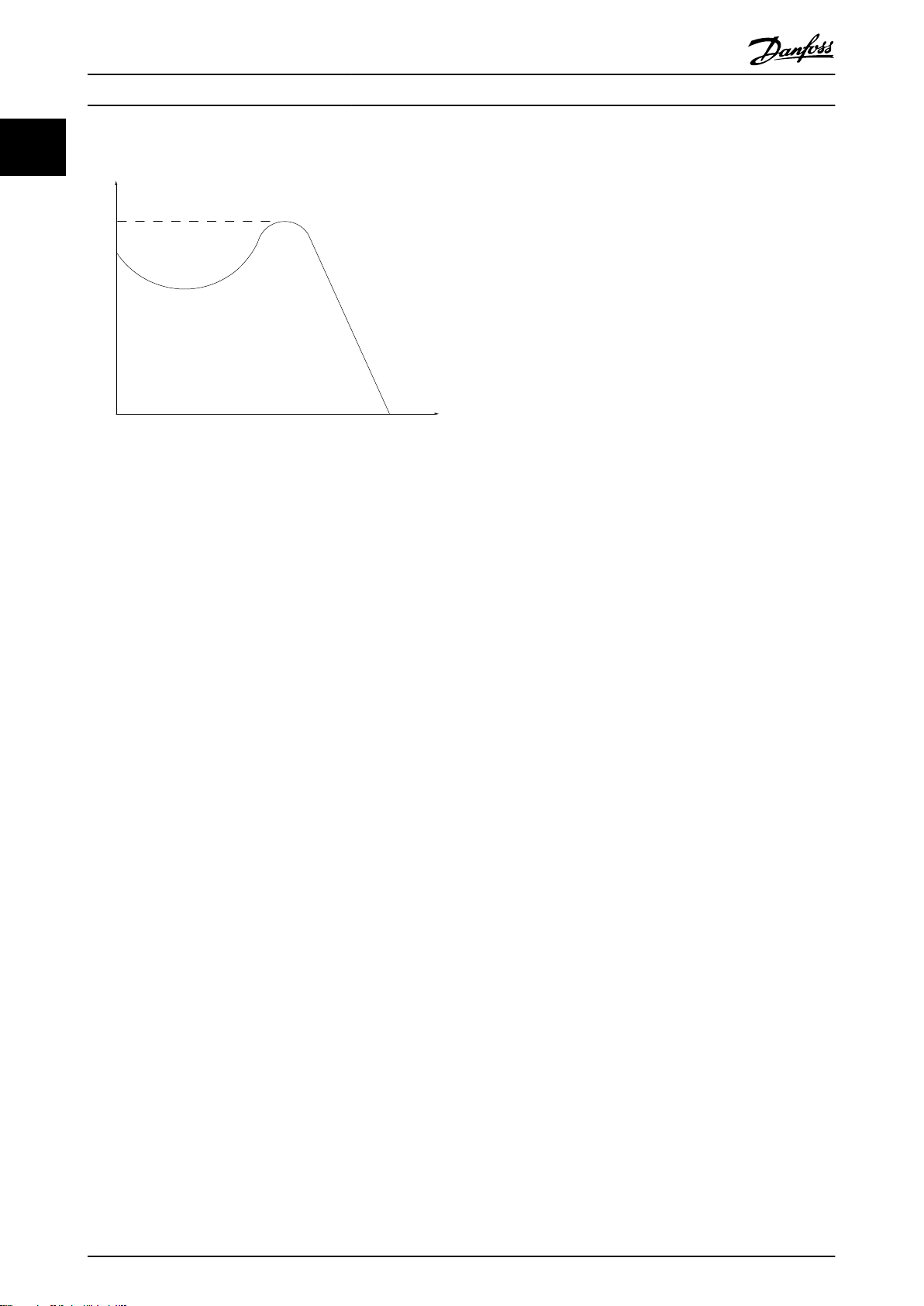
起步转矩
图 1.1 起步转矩
η
VLT
变频器效率被定义为输出功率和输入功率的比值。
启动 - 禁用命令
表 1.4
停止命令属于第 1 组的控制命令 – 请参阅
停止命令
请参阅
表 1.4
。
模拟参考值
传输到模拟输入端 53 或 54 的信号。该信号可为电压或
电流。
电流输入: 0–20 mA 和 4–20 mA
•
电压输入: 0–10 V DC
•
总线参考值
传输到串行通讯端口(FC 端口)的信号。
预置参考值
定义的预置参考值,该值可在参考值的 -100% 到 +100%
范围内设置。可以通过数字端子选择的 8 个预置参考
值。
Ref
MAX
确定 100% 满额值(通常是 10 V、20 mA)时的参考值
输入和产生的参考值之间的关系。
中设置的最大参考值。
Ref
MIN
确定 0% 值(通常是 0 V、0 mA、4 mA)时的参考值输
入和产生的参考值之间的关系。在
值
中设置最小参考值。
模拟输入
模拟输入可用于控制变频器的各项功能。
模拟输入有两种类型:
•
•
模拟输出
模拟输出可提供 0-20 mA、4-20 mA 的信号,或者提供数
字信号。
电流输入: 0–20 mA 和 4–20 mA
电压输入: 0–10 V DC
参数 3-03 最大参考值
参数 3-02 最小参考
。
自动电机识别 (AMA)
AMA 算法可确定相连电动机处于静止状态时的电气参数,
并基于电动机电缆的长度对电阻进行补偿。
数字输入
数字输入可用于控制变频器的各项功能。
数字输出
变频器具有 2 个可提供 24 V 直流信号(最大 40 mA)
的固态输出。
继电器输出
变频器带有两个可编程的继电器输出。
ETR
电热继电器是基于当前负载及时间的热负载计算元件。其
作用是估计电动机温度,防止电动机过热。
正在初始化
如果执行了初始化(
可编程参数将恢复为默认设置。
参数 14-22 工作模式
灾模式记录。
间歇工作周期
间歇工作额定值是指一系列工作周期。每个周期包括一个
加载时段和卸载时段。操作可以是定期工作,也可以是非
定期工作。
LCP
本地控制面板 (LCP) 是对变频器进行控制和编程的完整
界面。IP20 设备上的控制面板为可拆卸型,IP54 设备上
的控制面板为固定型。可安装在距变频器最远 3 米(9.8
英尺)的位置,即安装在带有安装套件选件的前面板中。
低位 (lsb)
最小有效位。
MCM
Mille Circular Mil 的缩写,是美国测量电缆横截面积
的单位。1 MCM = 0.5067 mm2。
高位 (msb)
最大有效位。
联机/脱机参数
对联机参数而言,在更改了其数据值后,改动将立即生
效。按 [OK](确定)可激活脱机参数。
PI 控制器
PI 控制器可调节输出频率,使之与变化的负载相匹配,
从而维持所需的速度、压力、温度等。
RCD
漏电断路器。
设置
两个菜单中的参数设置可以保存起来。可在这 2 个参数
菜单之间切换,并在保持 1 个菜单有效时编辑另一个菜
单。
滑差补偿
变频器通过提供频率补偿(根据测量的电机负载)对电机
滑差进行补偿,以保持电机速度的基本恒定。
智能逻辑控制 (SLC)
SLC 是一系列用户定义的操作,当这些操作所关联的用户
定义事件被 SLC 判断为真时,将执行操作。
参数 14-22 工作模式
未初始化通信参数、故障日志或火
),变频器的
8 Danfoss A/S © 04/2018 全权所有。 MG18C841
Page 11
简介 设计指南
热敏电阻
温控电阻器被安装在需要监测温度的地方(变频器或电动
机)。
跳闸
当变频器遭遇过热等故障或为了保护电动机、过程或机械
装置时所进入的状态。只有当故障原由消失后,才能重新
启动,跳闸状态可通过激活复位来取消,在有些情况下还
可通过编程自动复位来取消。请勿因个人安全而使用跳
闸。
跳闸锁定
当变频器在故障状态下进行自我保护并且需要人工干预时
(例如,如果变频器在输出端发生短路)所进入的状态。
只有通过切断主电源、消除故障原因并重新连接变频器,
才可以取消锁定性跳闸。在通过激活复位或自动复位(通
过编程来实现)取消跳闸状态之前,禁止重新启动。请勿
因个人安全而使用跳闸。
VT 特性
可变转矩特性用于泵和鼓风机。
+
VVC
与标准电压/频率比控制相比,电压矢量控制 (VVC+) 可
在速度参考值发生改变或与负载转矩相关时提高动力特性
和稳定性。
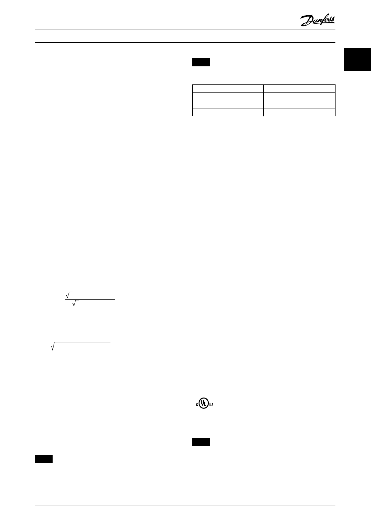
功率因数
1.7
功率因数表示变频器对主电源施加负载的程度。功率因数
是 I1 与 I
是总 RMS 电流,包括谐波电流。功率因数越小,相同功
率性能的 I
功率因数 =
三相控制的功率因数:
之间的比率,其中,I1 是基波电流,I
RMS
就越大。
RMS
3 × U × I1× cosϕ
3 × U × I
RMS
RMS
注意
具有集成安全功能的变频器必须符合机械指令。
EU 指令 版本
低电压指令 2014/35/EU
EMC 指令 2014/30/EU
ErP 指令
表 1.5 适用于变频器的 EU 指令
可根据请求提供合规性声明。
1.8.1.1 低电压指令
低压指令适用于电压范围为 50–1000 V 交流和 75–
1600 V 直流的所有电气设备。
该指令的目的是在其预期应用中,操作正确安装和维护的
电气设备时,确保个人安全,避免财产损失。
1.8.1.2 EMC 指令
EMC(电磁兼容性)指令的目的是降低电磁干扰,增加电气
设备和装置的抗干扰性。EMC 指令 2014/30/EU 的基本保
护要求规定,产生电磁干扰 (EMI) 或其运行可能受 EMI
影响的设备在设计时必须限制电磁干扰的产生,并且在正
确安装、维护和按预期方式使用情况下应具备适度的抗电
磁干扰等级。
独立使用或作为系统组成部分的电气设备必须带有 CE 标
志。无需 CE 标志的设备必须符合 EMC 指令的基本保护
要求。
1.8.1.3 ErP 指令
1 1
功率因数
I
= I
RMS
功率因数越高,表明不同的谐波电流越小。
借助该变频器内置的直流线圈可获得较高的功率因数,从
而可将对主电源施加的负载降低到最低程度。
1.8
变频器按照本部分所述的指令要求进行设计。
I1 × cosϕ1
=
I
RMS
2
2
+ I
5
2
+ . . + I
7
+ I
1
法规遵从性
I
1
=
因为cosϕ1 = 1
I
RMS
2
n
1.8.1 CE 标志
CE 标志 (Communauté européenne) 表示该产品制造商遵
守所有适用的 EU 指令。
设计和制造的 EU 指令。
表 1.5
中列出了适用于变频器
注意
CE 标志并不监管产品的质量。从 CE 标志中无法获得技
术规格信息。
ErP 指令为相关能量产品的欧盟生态化设计指令。该指令
规定了相关能量产品的生态化设计要求,包括变频器。该
指令的目的是提高能源供应安全性的同时,提高能效以及
环境保护水平。相关能量产品的环境影响包括整个产品生
命周期的能耗。
1.8.2 符合 UL
UL 列名
图 1.2 UL
注意
IP54 设备未通过 UL 认证。
变频器符合 UL 508C 温度存储要求。有关详细信息,请
参阅产品的专用设计指南中的
电机热保护
部分。
MG18C841 Danfoss A/S © 04/2018 全权所有。 9
Page 12
089
简介
VLT® HVAC Basic Drive FC 101
11
1.8.3 通过 RCM 认证
图 1.3 RCM 标志
RCM 认证标志表示符合电磁兼容性 (EMC) 的适用技术标
准。RCM 认证标志是澳大利亚和新西兰市场中电气和电子
设备必须带有的标志。RCM 认证标志的监管规定仅处理传
送和干扰辐射。对于变频器,使用 EN/IEC 61800-3 中指
明的辐射极限。可根据要求提供合规性声明。
1.8.4 EAC
图 1.4 EAC 标志
EurAsian Conformity(欧亚联盟技术认证,EAC) 标志表
示产品符合适用于欧亚关税同盟的产品的所有要求和技术
法规,该同盟由欧亚经济同盟的成员国组成。
产品铭牌和包装标签上必须都有 EAC 徽标。在 EAC 区域
内使用的所有产品都必须在 EAC 区域内的 Danfoss 购
买。
1.8.5 UkrSEPRO
图 1.5 UkrSEPRO
UKrSEPRO 认证确保制造稳定性以及产品和服务的质量和
安全性符合乌克兰监管标准。对于进出乌克兰领土的任何
产品,UkrSepro 证书是清关时的必需文件。
10 Danfoss A/S © 04/2018 全权所有。 MG18C841
Page 13
安全性 设计指南
2 安全性
2.1 具备资质的人员
要实现变频器的无故障和安全运行,必须保证正确可靠的
运输、存放、安装、操作和维护。仅允许具备资质的人员
安装或操作本设备。
具备资质的人员是指经过培训且经授权按照相关法律和法
规安装、调试和维护设备、系统和电路的人员。此外,该
人员还必须熟悉本指南中所述的说明和安全措施。
2.2 安全事项
警告
高电压
变频器与交流主电源输入线路、直流电源相连或负载共享
时带有高电压。如果执行安装、启动和维护工作的人员缺
乏资质,将可能导致死亡或严重伤害。
仅限具备资质的人员执行安装、启动和维护工
•
作。
在执行任何维护或修理作业之前,使用适当的电
•
压测量设备,以确保变频器上无剩余电压。
警告
意外启动
当变频器连接到交流主电源、直流电源或负载共享时,电
机可随时启动。在编程、维护或维修过程中意外启动可能
会导致死亡、严重人身伤害或财产损失。可利用外部开
关、现场总线命令、从 LCP 或 LOP 提供输入参考值信
号、通过 MCT 10 设置软件 的远程操作或消除故障状态
后启动电机。
要防止电机意外启动:
按 LCP 上的 [Off/Reset](停止/复位)键,然
•
后再设置参数。
断开变频器与主电源的连接。
•
将变频器连接到交流主电源、直流电源或负载共
•
享时,变频器、电机和所有驱动设备必须已完全
连接并组装完毕。
警告
放电时间
即使变频器未上电,变频器直流回路的电容器可能仍有
电。即使警告指示灯熄灭,也可能存在高压。在切断电源
后,如果在规定的时间结束之前就执行维护或修理作业,
则可能导致死亡或严重伤害。
停止电机。
•
断开交流主电源、远程直流电源(包括备用电
•
池)、UPS 以及与其它变频器的直流回路连接。
断开或锁定永磁电机。
•
请等待电容器完全放电。最短等待时间在
•
中指定。
在执行任何维护或修理作业之前,使用适当的电
•
压测量设备,以确保电容器已完全放电。
电压 [V] 功率范围 [kW (hp)] 最短等待时间(分钟)
3x200 0.25–3.7 (0.33–5) 4
3x200 5.5–11 (7–15) 15
3x400 0.37–7.5 (0.5–10) 4
3x400 11–90 (15–125) 15
3x600 2.2–7.5 (3–10) 4
3x600 11–90 (15–125) 15
表 2.1 放电时间
表 2.1
警告
漏电电流危险
漏电电流超过 3.5 mA。如果不将变频器正确接地,将可
能导致死亡或严重伤害。
由经认证的电气安装商确保设备正确接地。
•
警告
设备危险
接触旋转主轴和电气设备可能导致死亡或严重伤害。
确保只有经过培训且具备资质的人员才能执行安
•
装、启动和维护工作。
确保所有电气作业均符合国家和地方电气法规。
•
按照本手册中的过程执行。
•
2 2
MG18C841 Danfoss A/S © 04/2018 全权所有。 11
Page 14

安全性
VLT® HVAC Basic Drive FC 101
小心
内部故障危险
22
未正确关闭变频器时,变频器中的内部故障可能会导致严
重伤害。
接通电源前,确保所有安全盖板安装到位且牢靠
•
固定。
12 Danfoss A/S © 04/2018 全权所有。 MG18C841
Page 15
120
100
80
60
40
20
0
20 40 60 80 100 120 140 160 180
120
100
80
60
40
20
0 20 40 60 80 100 120 140 160 180
Volume %
Volume %
INPUT POWER % PRESSURE %
SYSTEM CURVE
FAN CURVE
A
B
C
130BA781.11
ENERGY
CONSUMED
产品概述 设计指南
3 产品概述
3.1 优点
3.1.1 为何要使用变频器控制鼓风设备和
泵设备?
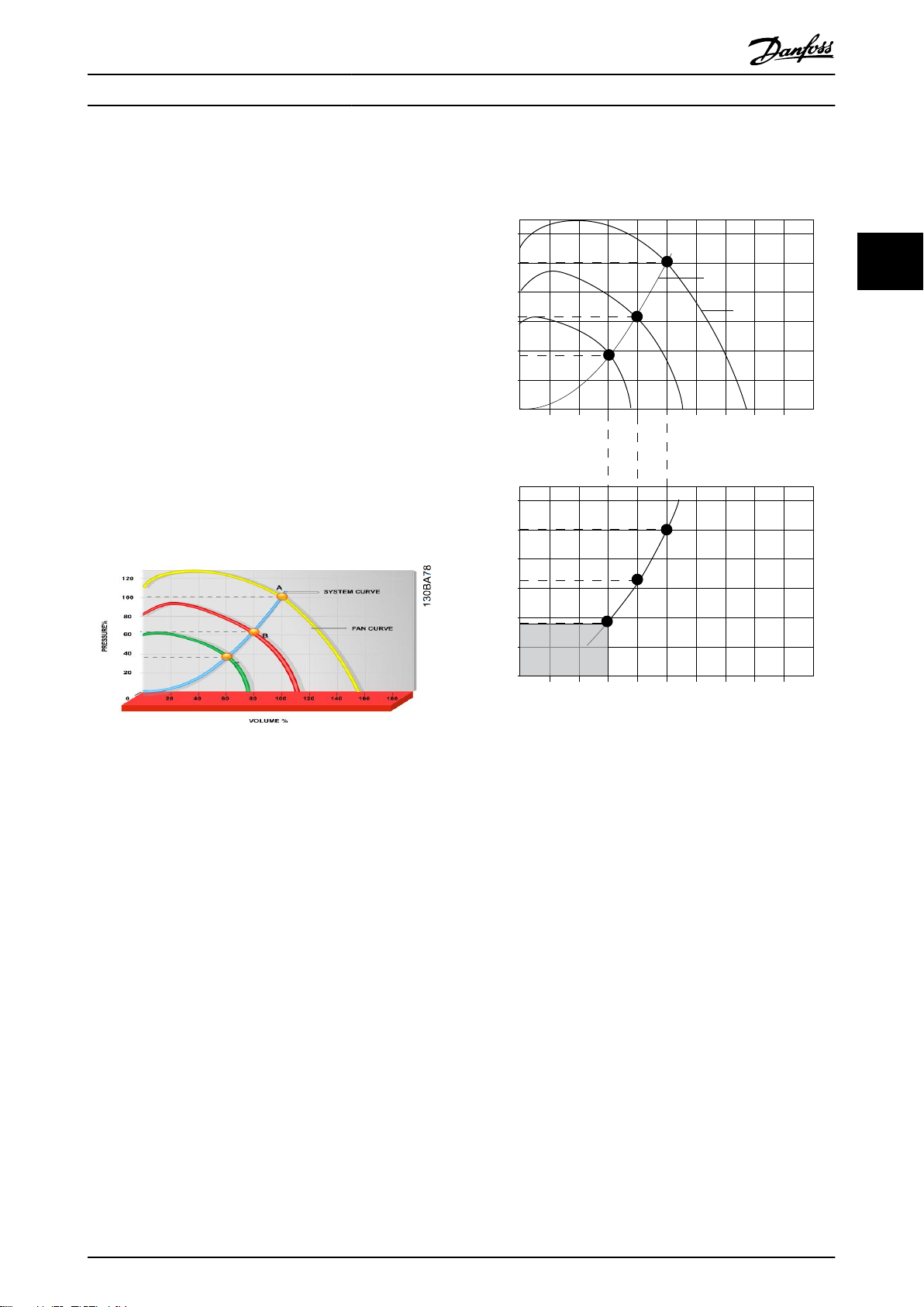
离心式鼓风设备和泵设备都服从这些设备所具有的比例法
则,这是变频器的立足点。有关详细信息,请参阅
章 3.1.3 节能示例
。
3.1.2 突出优点 - 节能
使用变频器控制风扇或泵的速度时,一个明显优点是可节
省电力。
同风扇和泵系统的其它替代控制系统和技术相比,变频器
是一种最理想的能量控制系统。
3 3
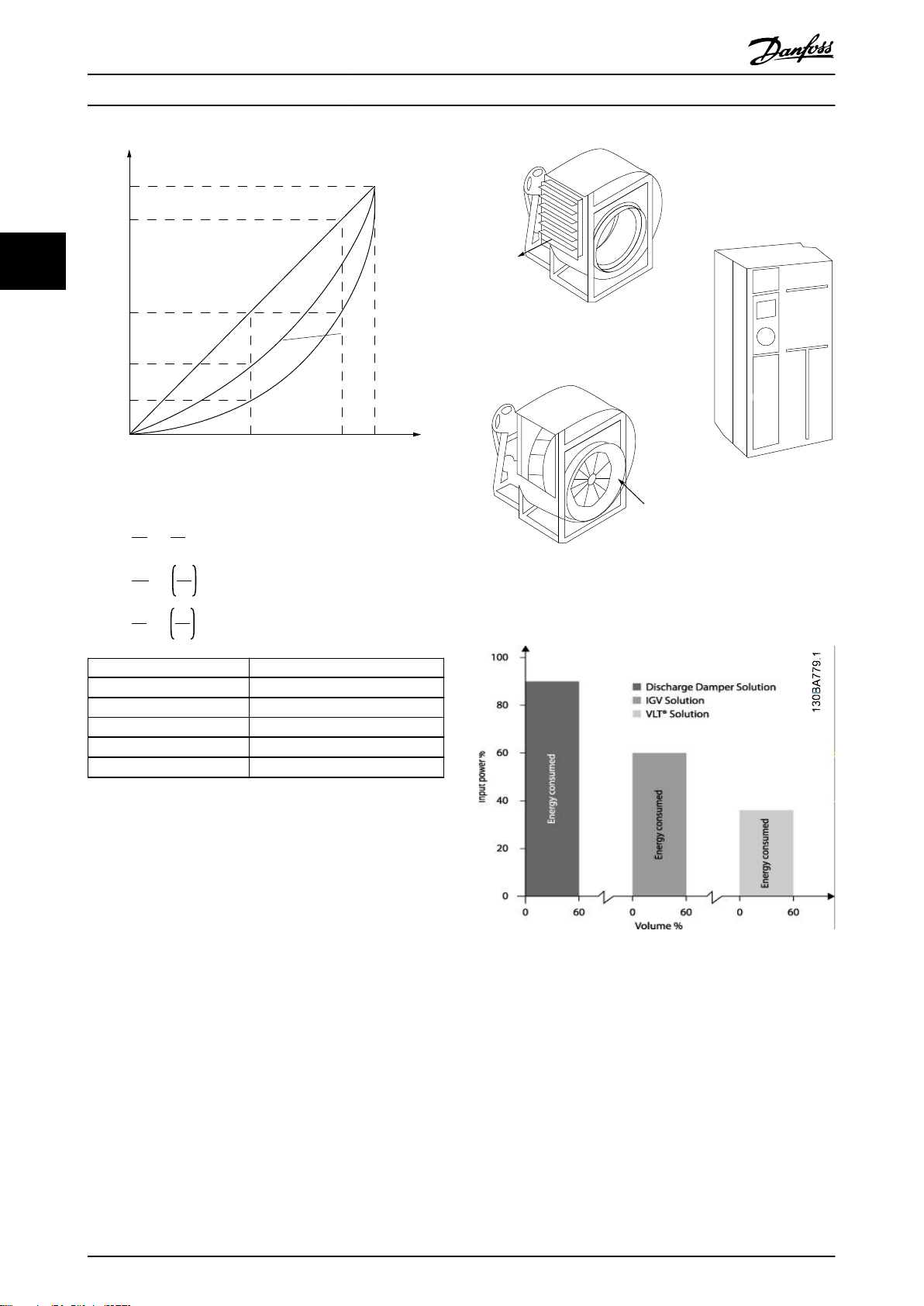
图 3.1 降低风扇容量时的风扇曲线(A、B 和 C)
图 3.2 使用变频器解决方案节能
使用变频器将风扇容量降低到 60% 时 - 在典型应用中可
以达到超过 50% 的能量节省。
3.1.3 节能示例
如
图 3.3
所示,通过更改 RPM 值,可以调节流量。只
需将速度从额定速度降低 20%,流量也会跟着降低 20%。
这是由于流量与转速直接成正比。而电力消耗将降低
50%。
如果目标系统仅需要在一年之中的若干天内提供 100% 的
流量,并且在其它时间的平均流量将低于额定流量的
80%,总节能量甚至会超过 50%。
图 3.3
描述了流量、压力以及功率消耗同转速之间的关
系。
MG18C841 Danfoss A/S © 04/2018 全权所有。 13
Page 16
n
100%
50%
25%
12,5%
50% 100%
80%
80%
175HA208.10
Power ~n
3
Pressure ~n
2
Flow ~n
130BA782.10
Discharge
damper
Less energy savings
IGV
Costlier installation
Maximum energy savings
产品概述
VLT® HVAC Basic Drive FC 101
33
图 3.3 比例法则
Q
n
1
流量
压力
功率
:
:
:
1
=
Q
n
2
2
H
1
=
H
2
P
1
=
P
2
2
n
1
n
2
3
n
1
n
2
图 3.4 三种常见节能系统
Q = 流量 P = 功率
Q1 = 额定流量 P1 = 额定功率
Q2 = 降低后的流量 P2 = 降低后的功率
H = 压力 n = 速度控制
H1 = 额定压力 n1 = 额定速度
H2 = 降低后的压力 n2 = 降低后的速度
表 3.1 比例法则
3.1.4 节能比较
与传统节能解决方案(比如排气调节门解决方案和进口导
叶 (IGV) 解决方案)相比, Danfoss 变频器解决方案提
供了重大的节能能力。这是因为变频器能够根据系统的热
负载控制风扇速度,而且变频器具有一项内置功能,该功
能使得变频器可以作为建筑管理系统 (BMS) 使用。
图 3.3
显示了当风扇容量降低,比如降低到 60% 时,3
个常见解决方案通常可实现的节能。
正如图中所示,在典型应用中可获得超过 50% 的节能。
图 3.5 节能
排风阀会降低能耗。入口导流箱提供了 40% 的降低,但
安装费用昂贵。Danfoss 变频器解决方案降低能耗超过
50% 并且安装简便。此外,还可降低噪音、机械应力并减
少磨损,延长整个应用的使用寿命。
14 Danfoss A/S © 04/2018 全权所有。 MG18C841
Page 17
500
[h]
t
1000
1500
2000
200100 300
[m
3
/h]
400
Q
175HA210.11
产品概述 设计指南
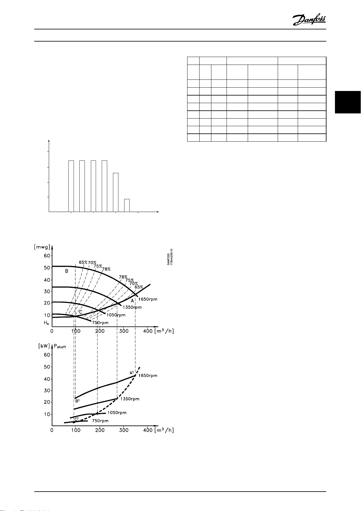
3.1.5 在一年当中流量有变化的示例
本示例的计算基于从泵数据表获得的泵特性。
获得的结果表明,在给定流量分布情况下,一年内的能量
节省超过 50%。投资回报期取决于每 kWh 的价格和变频
器的价格。在本示例中,与各种阀门和恒速相比较可以看
出,其投资回报期短于一年。
节能
P
= P
shaft
图 3.6 一年的流量分布
shaft output
3
m
350 5 438 42.5 18.615 42.5 18.615
300 15 1314 38.5 50.589 29.0 38.106
250 20 1752 35.0 61.320 18.5 32.412
200 20 1752 31.5 55.188 11.5 20.148
150 20 1752 28.0 49.056 6.5 11.388
100 20 1752 23.0 40.296 3.5 6.132
分布 阀门调节 变频器控制
/h
% 小时 功率
Σ
100 8760 – 275.064 – 26.801
表 3.2 结果
A1 - B
消
耗
kWh
1
功率
A1 - C
消
耗
kWh
1
3.1.6 更好的控制
用变频器控制系统流量或压力,可以实现更好的控制。
变频器可以对风扇或泵进行调速,从而实现对流量和压力
的可变控制。
另外,变频器还可以快速调整风扇或泵的速度,以便适应
系统中新的流量或压力条件。
利用内置的 PI 控制简化流程(流量、水平或压力)控
制。
3 3
3.1.7 不需要星形/三角形启动器或软启动
器
当启动大型电动机时,在许多国家都需要使用限制其启动
电流的设备。传统的系统普遍使用星形/三角形启动器或软
启动器。如果使用变频器,则不需要这些电动机启动器。
图 3.8
如
所示,变频器消耗的电流不会超过额定电流。
图 3.7 能源
MG18C841 Danfoss A/S © 04/2018 全权所有。 15
Page 18
Full load
% Full-load current
& speed
500
100
0
0 12,5 25 37,5 50Hz
200
300
400
600
700
800
4
3
2
1
175HA227.10
产品概述
VLT® HVAC Basic Drive FC 101
3.1.8 借助变频器实现省钱目的
章 3.1.9 不使用变频器
中的示例中展示了使用变频器替
代其他设备的情况。可以算一算安装这两种不同系统的成
本。示例中的两个系统可以用几近相同的价格搭建。
33
使用
章 1.5 其他资源
中引入的 VLT® Energy Box 软
件来计算可通过使用变频器实现的成本节省。
1
VLT® HVAC Basic Drive FC 101
2 星形/三角形启动器
3 软启动器
4 直接在电网上启动
图 3.8 启动电流
16 Danfoss A/S © 04/2018 全权所有。 MG18C841
Page 19
M
- +
M
M
x6 x6
x6
175HA205.12
Valve
position
Starter
Fuses
LV
supply
P.F.C
Flow
3-Port
valve
Bypass
Return
Control
Supply
air
V.A.V
outlets
Duct
P.F.C
Mains
Fuses
Starter
Bypass
supply
LV
Return
valve
3-Port
Flow
Control
Valve
position
Starter
Power
Factor
Correction
Mains
IGV
Mechanical
linkage
and vanes
Fan
Motor
or
actuator
Main
B.M.S
Local
D.D.C.
control
Sensors
PT
Pressure
control
signal
0/10V
Temperature
control
signal
0/10V
Control
Mains
Cooling section Heating section
Fan sectionInlet guide vane
Pump Pump
产品概述 设计指南
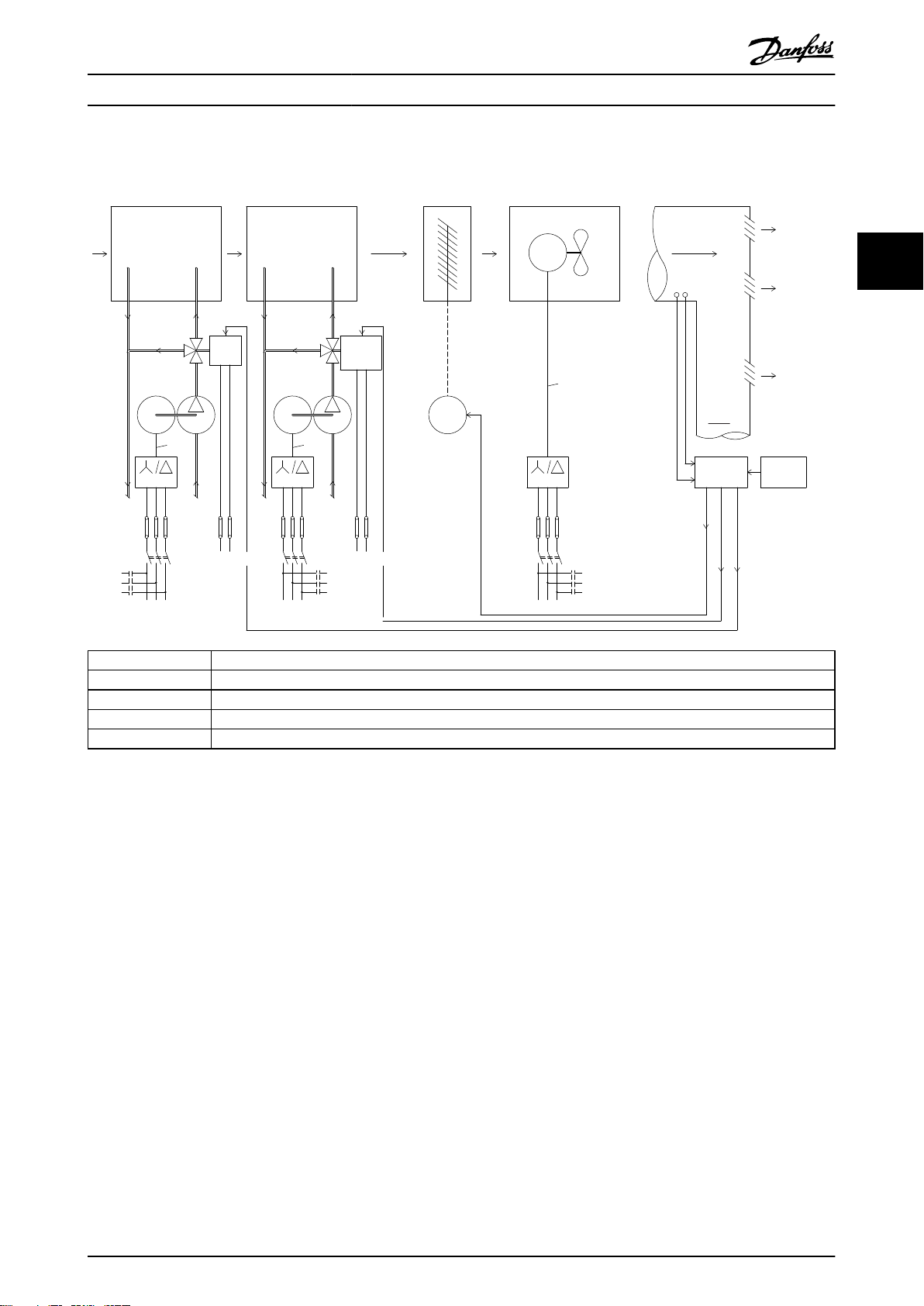
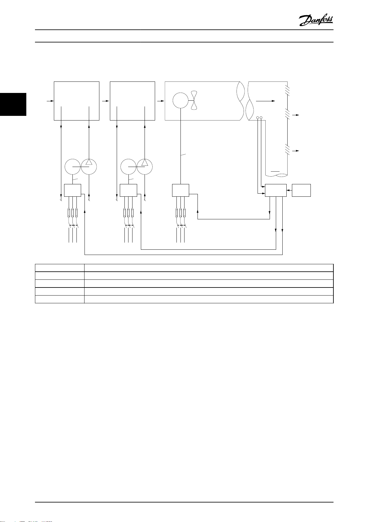
3.1.9 不使用变频器
3 3
D.D.C. 直接数字控制
E.M.S. 能量管理系统
V.A.V. 变风量
传感器 P 压力
传感器 T 温度
图 3.9 传统鼓风系统
MG18C841 Danfoss A/S © 04/2018 全权所有。 17
Page 20
175HA206.11
Pump
Flow
Return
Supply
air
V.A.V
outlets
Duct
Mains
Pump
Return
Flow
Mains
Fan
Main
B.M.S
Local
D.D.C.
control
Sensors
Mains
Cooling section Heating section
Fan section
Pressure
control
0-10V
or
0/4-20mA
Control
temperature
0-10V
or
0/4-20mA
Control
temperature
0-10V
or
0/4-20mA
VLT
M
- +
VLT
M
M
P
T
VLT
x3 x3
x3
产品概述
VLT® HVAC Basic Drive FC 101
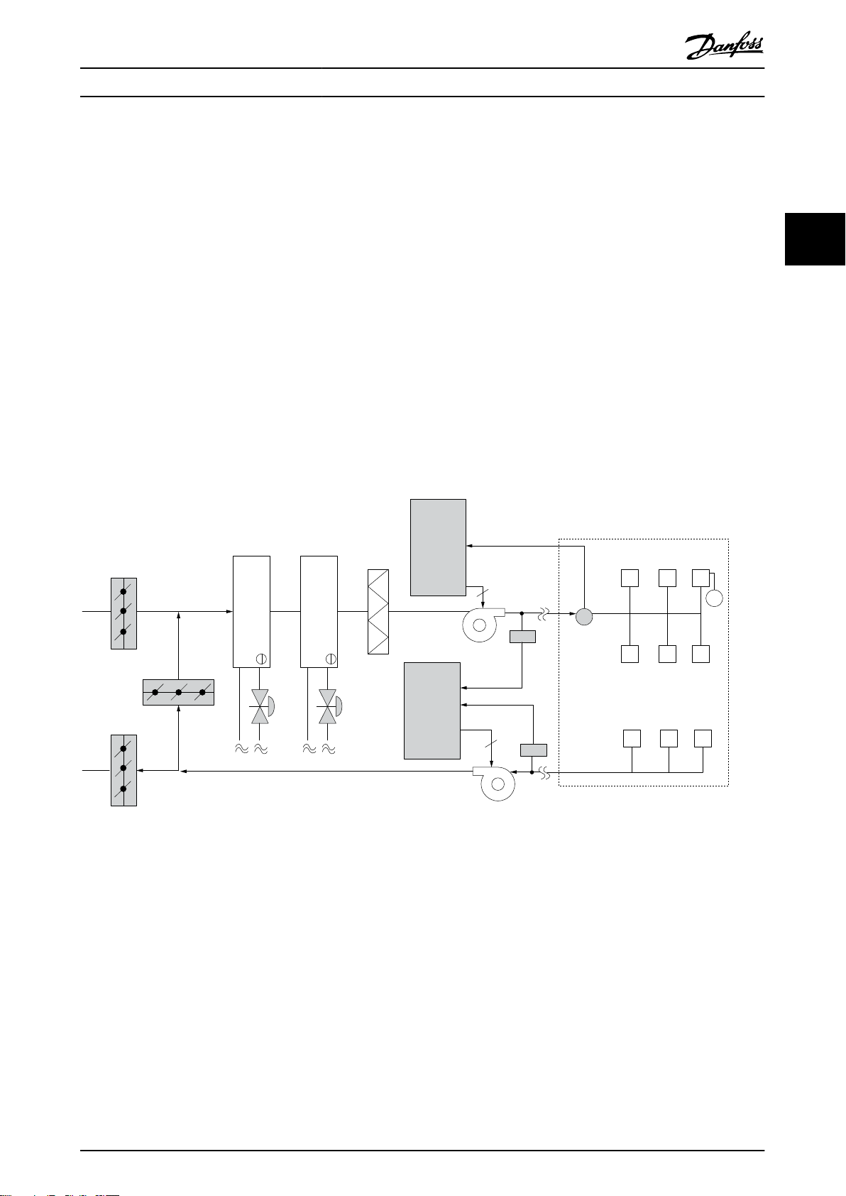
3.1.10 使用变频器
33
D.D.C. 直接数字控制
E.M.S. 能量管理系统
V.A.V. 变风量
传感器 P 压力
传感器 T 温度
图 3.10 由变频器控制的鼓风系统
18 Danfoss A/S © 04/2018 全权所有。 MG18C841
Page 21
Frequency
converter
Frequency
converter
D1
D2
D3
Cooling coil
Heating coil
Filter
Pressure
signal
Supply fan
VAV boxes
Flow
Flow
Pressure
transmitter
Return fan
3
3
T
130BB455.10
产品概述 设计指南
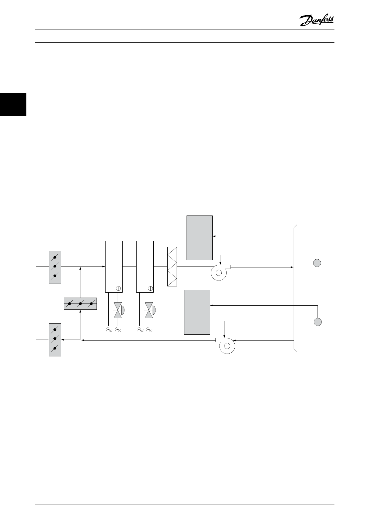
3.1.11 应用示例
以下章节介绍了典型的 HVAC 内应用示例。
3.1.12 变风量
VAV 或变风量系统用于同时控制通风和温度,以满足建筑物的要求。在对建筑物进行空气调节方面,使用中央 VAV 系统
被认为是最节能的方法。设计中央系统而不是分布式系统,可以实现更大的效力。
这要归功于使用了比小型电动机和分布式风冷冷却器更具效力的大型鼓风机和大型冷却器。更少的维护要求,也有助于实
现节省。
3.1.13
VLT® 解决方案
同联合使用阀门和 IGV 来保持管道系统的恒定压力相比,变频器解决方案可以大幅度节省能量,并且降低安装的复杂程
度。变频器不会造成人为的压力下降或者导致鼓风系统的效率降低,它通过降低鼓风系统的速度来提供系统所要求的流量
和压力。
离心式设备(如鼓风机)的行为遵从离心法则。这意味着鼓风机在速度降低时可以减小它们产生的压力和流量。它们的能
耗也因此被大幅度降低。
使用 VLT® HVAC Basic Drive FC 101 的 PI 控制器时,可以不再需要其他控制器。
3 3
图 3.11 变风量
MG18C841 Danfoss A/S © 04/2018 全权所有。 19
Page 22
Frequency
converter
Frequency
converter
Pressure
signal
Cooling coil
Heating coil
D1
D2
D3
Filter
Pressure
transmitter
Supply fan
Return fan
Temperature
signal
Temperature
transmitter
130BB451.10
产品概述
VLT® HVAC Basic Drive FC 101
3.1.14 定风量
含量降低后,可减缓送风设备的速度。而回风设备将作出
调整,以保持静态的压力设置点或保持送风量和回风量之
定风量 (CAV) 系统是一种中央通风系统,通常用于向大
间的恒定差值。
型的公共区域提供一定量经过调节的新鲜空气。它们的出
现时间早于 VAV 系统,因此可以在较早的多区域商业建
筑中看到它们。这些系统利用配备有加热线圈的空气处理
33
设备 (AHU) 对一定量的新鲜空气进行预热,其中许多系
统还用于对建筑物进行空气调节并且带有制冷线圈。为了
帮助实现各个区域的加热和制冷要求,通常都会使用通风
线圈设备。
对于温度控制,尤其是在空调系统中使用温度控制时,随
着外部温度的变化以及受控区域内人数的变化,会存在不
同的制冷要求。当温度降到设置点以下时,送风设备可以
放慢其速度。回风设备保持静态的压力设置点。减少了空
气流量,也就减少了用于加热或制冷新鲜空气的能量,从
而进一步提高了节能水平。
DanfossHVAC 专用变频器的多个功能可用于增强 CAV 系
3.1.15
VLT® 解决方案
统的性能。在通风系统的控制中,人们比较关心空气的质
量。可以设置变频器的最低可编程频率,因此不论反馈或
变频器不仅能实现明显的节能效果,而且还可以保持对建
筑物的完美控制。可以使用温度传感器或二氧化碳传感器
作为变频器的反馈信号。不论是控制温度、空气质量还是
同时控制这二者,都可以按照建筑物的实际情况来控制
CAV 系统的运转。在受控区域内,如果人数减少,则对新
鲜空气的需求也会降低。二氧化碳传感器检测到二氧化碳
参考信号如何,都能保持一个最低水平的送风量。变频器
还包括一个 PID 控制器,通过它可以同时监测温度和空
气质量。因此,即使已达到温度要求,变频器也会根据空
气质量传感器的信号保持足够的送风。该控制器可通过监
测和比较两个反馈信号来控制回风设备,从而在送风和回
风管道之间保持恒定的空气流量差。
图 3.12 定风量
20 Danfoss A/S © 04/2018 全权所有。 MG18C841
Page 23
Frequency
converter
Water Inlet
Water Outlet
CHILLER
Temperature
Sensor
BASIN
Conderser
Water pump
Supply
130BB453.10
产品概述 设计指南
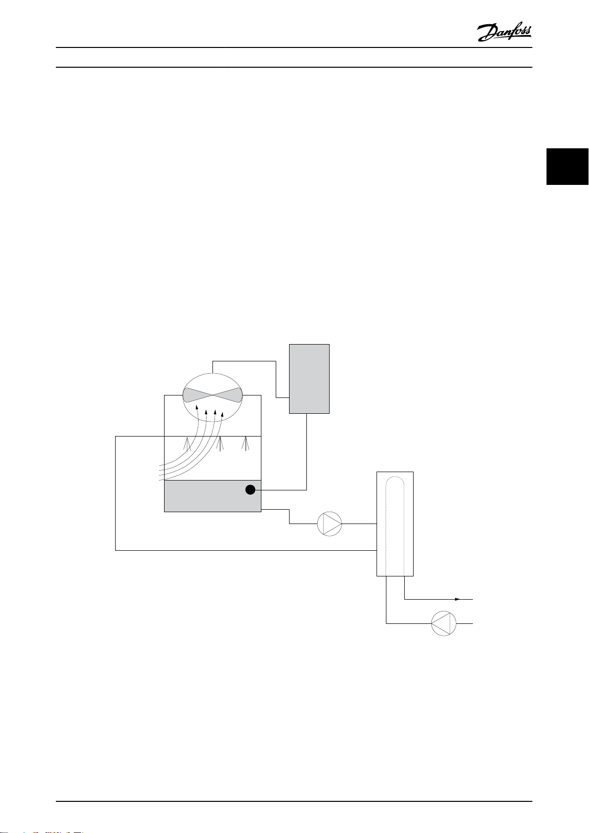
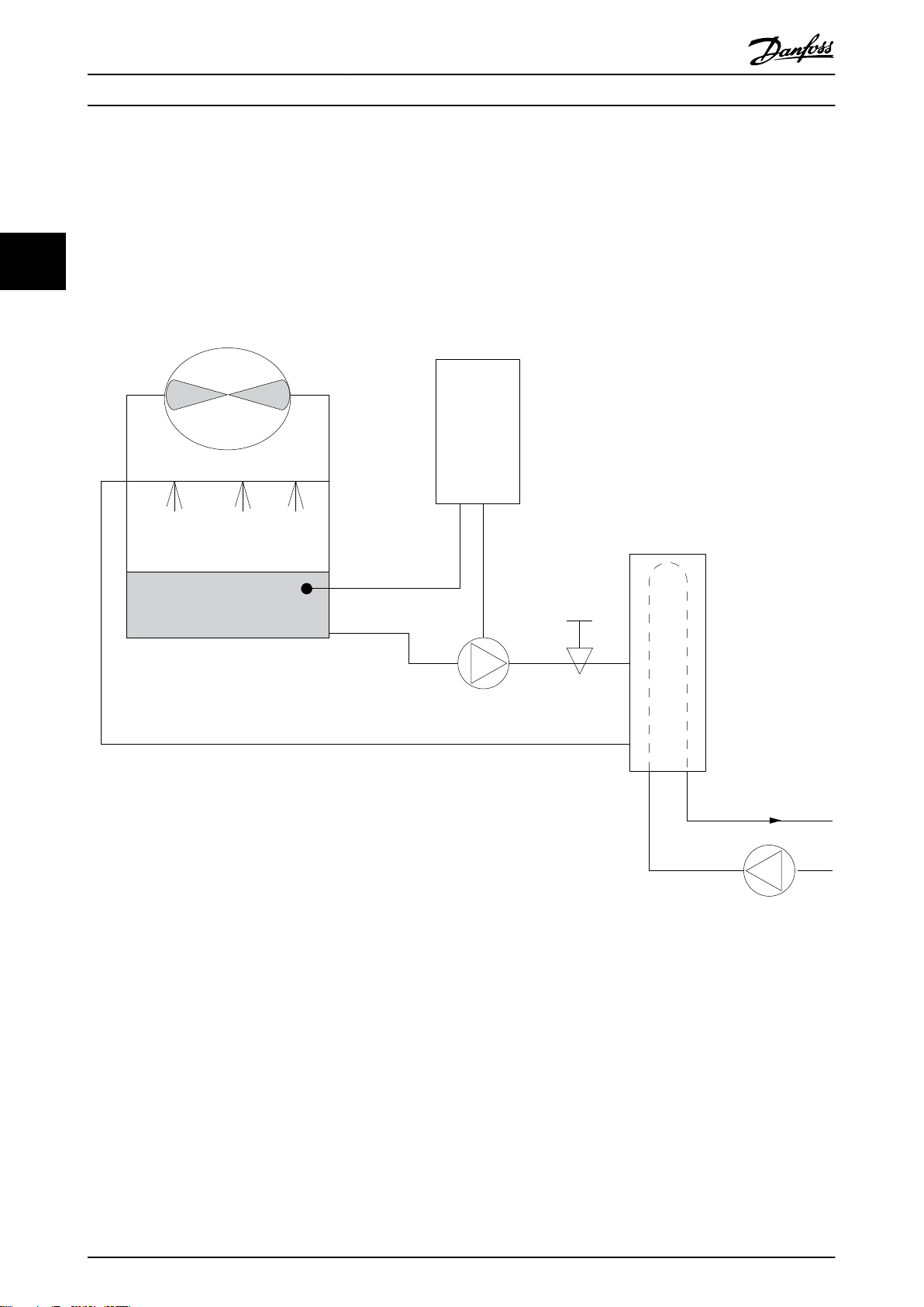
3.1.16 冷却塔鼓风机
冷却塔鼓风机用于冷却水冷冷却器系统中的冷凝水。水冷
冷却器是获得冷却水的最有效方式。同风冷冷却器相比,
其效力高出 20%。根据气候的不同,在降低冷却器的冷却
用水温度的所有方法中,冷却塔通常具有最出色的节能效
果。
它们通过蒸发来降低冷却用水的温度。
为了增大冷却塔的冷却表面积,冷却用水被喷洒在冷却塔
内的冷却塔“填料”上。冷却塔鼓风机将空气吹到填料和
喷洒的水上,以促进水的蒸发。蒸发带走了水的能量,从
而使水温降低。冷却水汇聚在冷却塔的水槽中,它们在此
又被抽送回冷却器,这个过程周而复始。
3.1.17
使用 VLT® 变频器可以将冷却塔鼓风机的速度控制在保持
冷却用水温度所要求的水平上。VLT® 变频器还可以根据
需要打开和关闭鼓风机。
VLT® 解决方案
Danfoss 专用变频器的多个功能可用于提高冷却塔鼓风机
应用的性能。随着冷却塔鼓风机的速度下降到某个水平,
鼓风机对水冷却的作用将变得微乎其微。另外,在使用变
速箱来控制冷却塔鼓风机的频率时,可能至少需要达到
40-50% 的速度。
即使反馈或速度参照值要求更低的速度,由用户编程的最
小频率设置也可以保持该最低频率。
作为一种标准功能,您还可以对变频器编程,让它进入休
眠模式并且停止鼓风机,直到需要更高的速度。再者,某
些冷却塔鼓风机的频率可能导致震动,这是您不愿见到
的。通过在变频器中设置旁路频率范围,您可以轻而易举
地避免这些频率。
3 3
图 3.13 冷却塔鼓风机
MG18C841 Danfoss A/S © 04/2018 全权所有。 21
Page 24
Frequency
converter
Water
Inlet
Water
Outlet
BASIN
Flow or pressure sensor
Condenser
Water pump
Throttling
valve
Supply
CHILLER
130BB452.10
产品概述
VLT® HVAC Basic Drive FC 101
3.1.18 冷凝器泵
冷却水泵主要用于控制水冷冷却器的冷却部分及其对应冷
却塔中的水循环。冷却用水会吸收冷却器冷却部分的热
3.1.19
VLT® 解决方案
可以在冷却器的水泵上添加变频器,而不必用节流阀调节
水泵或修整泵轮。
量,并且将热量释放到冷却塔内的空气中。在获得冷却水
方面,这些系统可以提供最为有效的方式。同风冷冷却器
33
相比,其效力高出 20%。
同使用减压阀相比,使用变频器将可以直接节省由减压阀
吸收的能量。合计起来看,这可以实现 15-20% 或更高的
节省水平。泵轮在修整后无法复原,因此,一旦由于情况
发生变化而需要更高流量时,就必须更换泵轮。
图 3.14 冷凝器泵
22 Danfoss A/S © 04/2018 全权所有。 MG18C841
Page 25
Frequency
converter
Frequency
converter
CHILLER
CHILLER
Flowmeter
Flowmeter
F F
130BB456.10
产品概述 设计指南
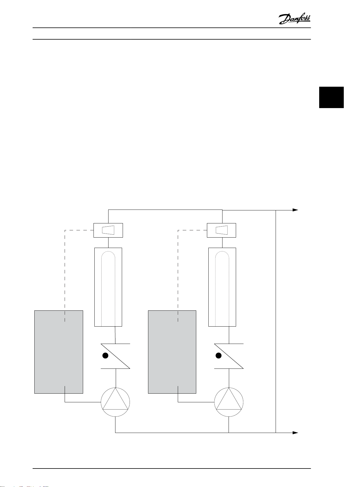
3.1.20 主泵
在主/辅助泵系统中,可以使用主泵来为那些在遇到不稳定
的流量时难以操作或控制的设备提供恒定的流量。主/辅助
泵技术使得主要的生产性循环可以同辅助的配送循环分离
开来。借此,冷却器等设备可以获得恒定的设计流量并且
实现正常运行,同时允许系统的其余部分存在流量变化。
当冷却器中的蒸发器流速降低时,冷却水将开始变得过
冷。发生该现象时,冷却器会试图减弱其冷却能力。如果
流速下降过大,或者过快,以致于冷却器无法充分地将其
负载分流,冷却器的保险装置将使冷却器跳闸,此时需要
进行手工复位。在大型系统中,尤其是并行安装了两个或
多个冷却器时,如果不使用主/辅助泵技术,会经常发生这
种情况。
3.1.21
系统的规模以及主循环的规模不同,主循环的能耗也可能
大相径庭。
VLT® 解决方案
在主系统中添加变频器,可以替代减压阀和/或避免进行泵
轮调整,从而降低运行开销。有两种常用的控制方法:
流量计
由于要实现的流速是已知的并且恒定,因此,只要在每个
冷却器的出口安装一个流量计,就可以对泵设备进行直接
控制。借助内置的 PI 控制器,变频器可以始终保持适宜
的流速,从而在冷却器及其泵系统打开和关闭的过程中可
以为主管道循环中变化的阻力提供均衡补偿。
本地速度确定
操作员只需降低输出频率,直到获得设计的流速。
使用变频器降低泵速同调整泵轮极其相似,只不过它不需
要任何人力,并且泵设备可以保持更高的效力。平衡压缩
机会直接降低泵速,直到获得所希望的流速并且可保持该
速度的恒定。当冷却器切入后,泵将在这个速度下工作。
由于主循环中没有控制阀或其它可能导致系统曲线发生变
化的设备,并且由于切入泵设备和冷却器而导致的变化通
常很小,因此该固定速度会始终保持在适宜水平。如果在
系统使用期间需要增加流速,变频器可以直接增加泵速,
而不需要使用新泵轮。
3 3
图 3.15 主泵
MG18C841 Danfoss A/S © 04/2018 全权所有。 23
Page 26
Frequency
converter
Frequency
converter
CHILLER
CHILLER
3
3
P
130BB454.10
产品概述
VLT® HVAC Basic Drive FC 101
3.1.22 辅助泵
在主/辅助水冷泵系统中,辅助泵负责将主要生产循环的冷
却水配送到负载处。主/辅助泵系统用于循环性温度控制,
并且可以将一个管道循环同另一个管道循环分离开来。在
这种情况下,主泵用于保持冷却器的恒定流量,同时允许
33
辅助泵有流量变化,这不仅增强了控制能力,而且还节省
了能量。
如果在流量可变的系统设计中未使用主/辅助式概念,则当
流速下降过大或过快时,冷却器将无法正确分流其负载。
此时,冷却器的蒸发器低温保护装置会使冷却器跳闸,从
而需要手工复位。在大型系统中,尤其是并行安装了两个
或多个冷却器时,会经常发生这种情况。
3.1.23
这种使用了双向阀的主-辅助式系统实现了更高的节能水
平,并且简化了系统控制问题,但只有添加了变频器,才
能真正实现节能和控制能力。
VLT® 解决方案
在正确安装了传感器的情况下,添加变频器可以让泵按照
系统曲线而不是泵曲线来改变速度。
这样既避免了能量浪费,又避免了双向阀可能遭遇的大多
数过压现象。
当达到监控的负载时,双向阀会关闭。这增大了在负载和
双向阀中测得的压力差。当这个压力差开始增大时,泵将
减速以保持控制方向,同时调用给定值。该给定值是在设
计条件下通过合计负载和双向阀的压降来计算的。
注意
当并行运行多个泵 时,使用几个单独的专用变频器,或
者同时运行多个泵的一个变频器,以提高节能水平,这些
泵必须使用相同的速度。
图 3.16 辅助泵
24 Danfoss A/S © 04/2018 全权所有。 MG18C841
Page 27
130BB892.10
100%
0%
-100%
100%
Local
reference
scaled to
Hz
Auto mode
Hand mode
LCP Hand on,
off and auto
on keys
Local
Remote
Reference
Ramp
P 4-10
Motor speed
direction
To motor
control
Reference
handling
Remote
reference
P 4-14
Motor speed
high limit [Hz]
P 4-12
Motor speed
low limit [Hz]
P 3-4* Ramp 1
P 3-5* Ramp 2
Hand
On
Off
Reset
Auto
On
130BB893.10
产品概述 设计指南
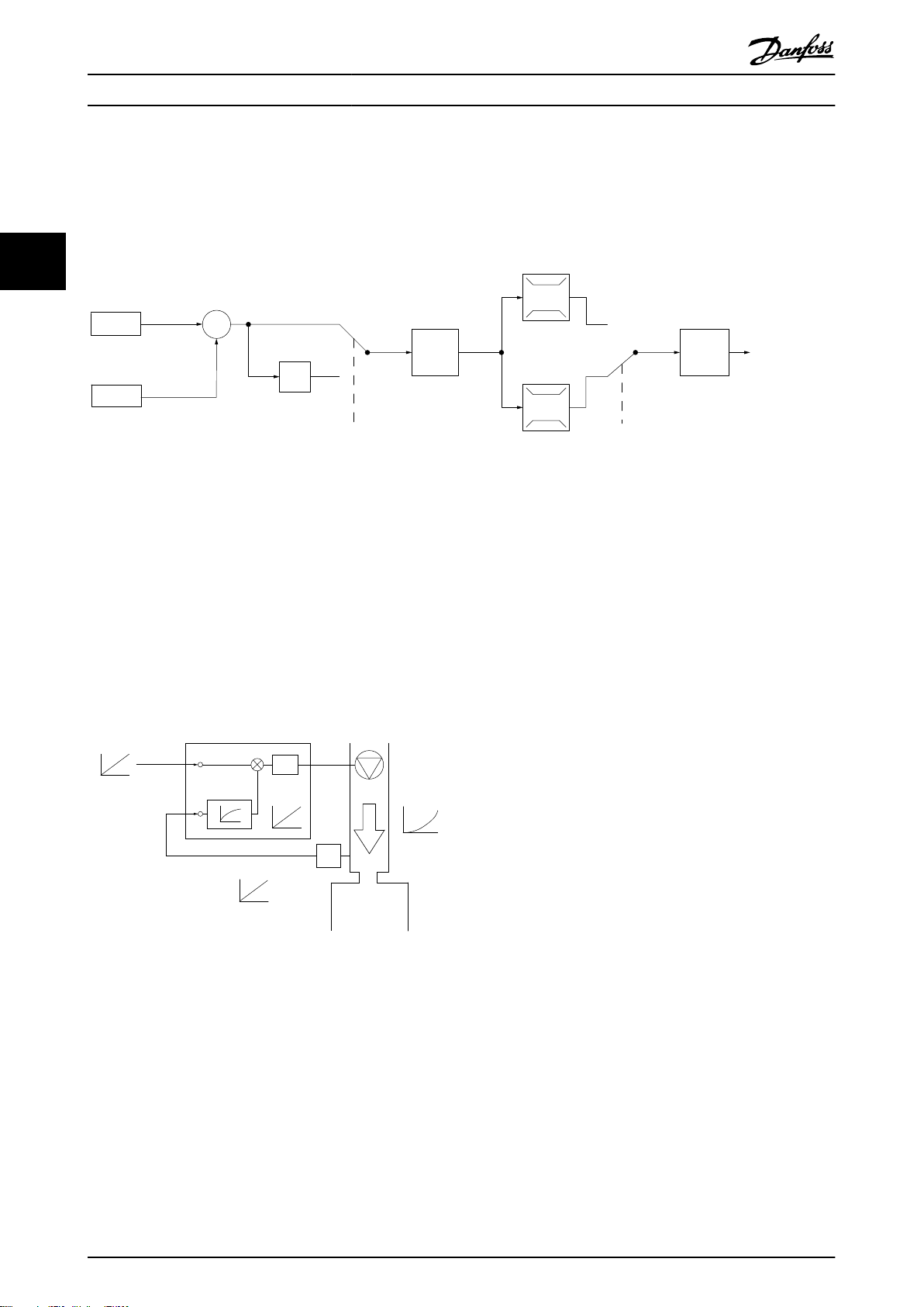
3.2 控制结构
在
参数 1-00 配置模式
中选择
[0] 开环 或 [1] 闭环
3.2.1 开环控制结构
图 3.17 开环结构
。
3 3
在
图 3.17
环 [0]
所示的配置中,
参数 1-00 配置模式
被设为
开
。在收到了参考值处理系统的最终参考值或本地参
3.2.3 本地(手动启动)和远程(自动启
动)控制
考值后,首先会对最终参考值进行加减速限制和速度限
制,然后才将它发送给电机控制。因此,电机控制的输出
便会受到频率上限的限制。
3.2.2 PM/EC+ 电动机控制
Danfoss EC+ 概念使得在 IEC 标准机架规格中使用由
Danfoss 变频器操作的高效永磁电机成为可能。
其调试程序与现有的通过采用 Danfoss VVC+ PM 控制策
您可以通过本地控制面板 (LCP) 以手动方式运行变频
器,也可以借助模拟/数字输入或串行总线远程运行变频
器。如果
数 0-44 LCP 的 [Off/Reset] (停止/复位)键
数 0-42 LCP 的 [Auto on]键
参数 0-40 LCP 的 [Hand On]键、参
和
中允许,则可以通过按
LCP 上的 [Hand On](手动启动)和 [Off/Reset](关
闭/复位)来启动和停止变频器。通过 [Off/Reset](关
闭/复位) 键可将报警复位。
参
略进行的异步(感应)电动机调试程序相当。
对客户的好处:
自由选择电机技术(永磁或感应电动机)。
•
安装和操作与感应电机相同。
•
在选择系统组件(比如电机)时不受厂商限制。
•
通过选择最佳组件,实现最高系统效率。
•
可以改造现有系统。
•
功率规格: 45 kW (60 hp) (200 V)、0.37–
•
图 3.18 LCP 键
不论的设置为何,本地参考值都将强制使
配置模式变为开环。
模式
参数 1-00 配置
90 kW (0.5–121 hp) (400 V)、90 kW (121
hp) (600 V)(感应电机)和 0.37–22 kW
在关机时将恢复本地参考值。
(0.5–30 hp) (400 V)(永磁电机)。
PM 电机的电流限制:
当前仅支持不超过 22 Kw (30 hp) 的规格。
•
永磁电动机不支持 LC 滤波器。
•
•
•
•
MG18C841 Danfoss A/S © 04/2018 全权所有。 25
对于永磁电动机不支持借能运行算法。
仅支持系统中定子电阻 Rs 的完整 AMA。
不检测停顿(自软件版本 2.80 开始支持)。
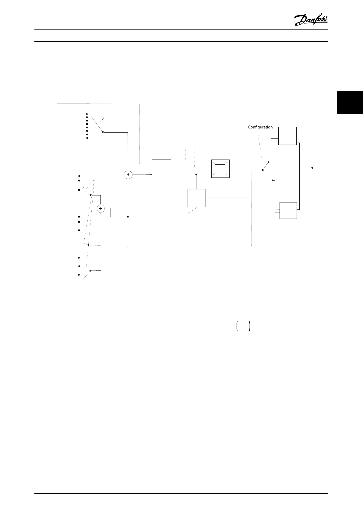
3.2.4 闭环控制结构
内部闭环控制器使得变频器可以成为受控系统的一个组成
部分。变频器接收来自系统中某个传感器的反馈信号。它
随后将此反馈与设置点参考值进行比较,以确定这两个信
号之间的误差(如果存在)。然后,它会调整电机速度来
纠正该误差。
Page 28
7-30 PI
Normal/Inverse
Control
PI
Reference
Feedback
Scale to
speed
P 4-10
Motor speed
direction
To motor
control
130BB894.11
S
100%
0%
-100%
100%
*[-1]
_
+
130BB895.10
+
-
PI
P
P
P
Ref.
signal
Desired
ow
FB conversion
Ref.
FB
Flow
FB
signal
Flow
P 20-01
产品概述
VLT® HVAC Basic Drive FC 101
以下面的泵应用为例:为了将管道中的静态压力保持在恒
定水平,此应用需要对泵速进行控制。静态压力值以给定
值参照值的方式提供给变频器。静态压力传感器测量管道
减慢速度来将压力降低。同样,如果管道压力低于设置点
参考值,则变频器会通过自动加快速度来增大泵提供的压
力。
中的实际静态压力,并以反馈信号方式将此信息提供给变
频器。如果反馈信号大于给定值参考值,则变频器会通过
33
图 3.19 闭环控制结构
变频器闭环控制器的默认值通常可以提供令人满意的性
能,但通过调整参数,通常可以优化系统控制。
3.2.5 反馈转换
在某些应用中对反馈信号进行转换显得非常有用。使用压
力信号来提供流量反馈是这方面的一个例子。由于压力的
平方根同流量成正比,因此,通过压力信号的平方根会得
到一个与流量成正比的值。请参阅
图 3.20 反馈信号转换
图 3.20
。
26 Danfoss A/S © 04/2018 全权所有。 MG18C841
Page 29
Speed open
loop
mode
Input command:
freeze reference
Process
control
Scale to
Hz
Scale to
process
unit
Remote
reference/
setpoint
±200%
Feedback
handling
Remote
reference in %
maxRefPCT
minRefPct
min-max ref
Freeze
reference &
increase/
decrease
reference
±100%
Input commands:
Speed up/speed down
±200%
Relative
reference
=
X+X*Y/100
±200%
External reference in %
±200%
Parameter choise:
Reference resource 1,2,3
±100%
Preset reference
Input command:
preset ref bit0, bit1, bit2
+
+
Relative scalling reference
Intern resource
Preset relative reference
±100%
Preset reference 0 ±100%
Preset reference 1 ±100%
Preset reference 2 ±100%
Preset reference 3 ±100%
Preset reference 4 ±100%
Preset reference 5 ±100%
Preset reference 6 ±100%
Preset reference 7 ±100%
External resource 1
No function
Analog reference
±200 %
Local bus reference
±200 %
Pulse input reference
±200 %
Pulse input reference
±200 %
Pulse input reference
±200 %
External resource 2
No function
Analog reference
±200 %
Local bus reference
±200 %
External resource 3
No function
Analog reference
±200 %
Local bus reference
±200 %
Y
X
130BE842.10
产品概述 设计指南
3.2.6 参考值处理
开环和闭环操作的详细信息。
3 3
图 3.21 框图显示了远程参考值
远程参考值包括:
•
•
•
•
在变频器中最多可以设置 8 个预置参考值。可以使用数
字输入或串行通讯总线来选择有效的预置参考值。参考值
也可以从外部提供(通常是借助某个模拟输入)。这种外
部来源可通过 3 个参考值来源参数(
来源 1、参数 3-16 参考值 2 来源
值 3 来源
参考值相加,便得到总的外部参考值。可以选择外部参考
值、预置参考值或这两者的和作为有效参考值。最后,可
以使用
定。
MG18C841 Danfoss A/S © 04/2018 全权所有。 27
预置参考值。
外部参考值(模拟输入和串行通讯总线参考
值)。
预置相对参考值。
由反馈控制的设置点。
参数 3-15 参考值
和
参数 3-17 参考
)中的其中一个来选择。所有参考值源和总线
参数 3-14 预置相对参考值
对该参考值进行标
标定后的参考值按如下方式计算:
参考值
= X + X ×
其中,X 是外部参考值、预置参考值或这两者的和,而 Y
是一个百分比形式的
如果将 Y(即
Y
100
参数 3-14 预置相对参考值
参数 3-14 预置相对参考值
)设置为
0%,则参考值将不受标定的影响。
。
Page 30
110%
100%
90 %
80
%
70 %
60 %
50 %
40 %
30 %
20 %
10 %
0
I
out
[%]
0
2
5
10
16
40
o
C
50
o
C
45
o
C
fsw[kHz]
130BC217.10
fsw[kHz]
20 10
0
10%
20%
30%
40%
50%
60%
70%
80%
90%
100%
110%
I
out
[%]
16
40
45
50
5
o
C
o
C
o
C
104 oF
113 oF
122
o
F
fsw[kHz]
20 10
0
10%
20%
30%
40%
50%
60%
70%
80%
90%
100%
110%
I
out
[%]
16
40
45
50
5
o
C
o
C
o
C
130BC219.10
fsw[kHz]
20 10
0
10%
20%
30%
40%
50%
60%
70%
80%
90%
100%
110%
I
out
[%]
16
5
130BC220.11
40
45
50
o
C
o
C
o
C
104 oF
113 oF
122
o
F
产品概述
VLT® HVAC Basic Drive FC 101
3.2.7 调整变频器的闭环控制器
一旦设置了变频器的闭环控制器,便应测试该控制器的性
能。在使用
数 20-94 PI 积分时间
参数 20-93 PI 比例增益
的默认值时,通常都能实现可接
和
参
受的性能。但在某些时候可能需要对这些参数值进行优
33
化,以实现更快的系统响应,同时仍能控制速度过冲。
3.2.8 手动 PI 调整
1. 启动电动机。
2. 将
3. 接着降低 PI 比例增益,直到反馈信号变稳定。
4. 将比例增益降低 40-60%。
5. 将
6. 增大 PI 积分时间,直到反馈信号变稳定。
7. 将积分时间增加 15-50%。
参数 20-93 PI 比例增益
设为 0.3, 并增
大该值直到反馈信号开始发生振荡时为止。如果
需要,可以启动和停止变频器或通过逐步更改给
定值参照值来尝试引起振荡。
参数 20-94 PI 积分时间
设为 20 秒,然
后逐渐减小该值直到反馈信号开始发生振荡时为
止。如果需要,可以启动和停止变频器或通过逐
步更改给定值参照值来尝试引起振荡。
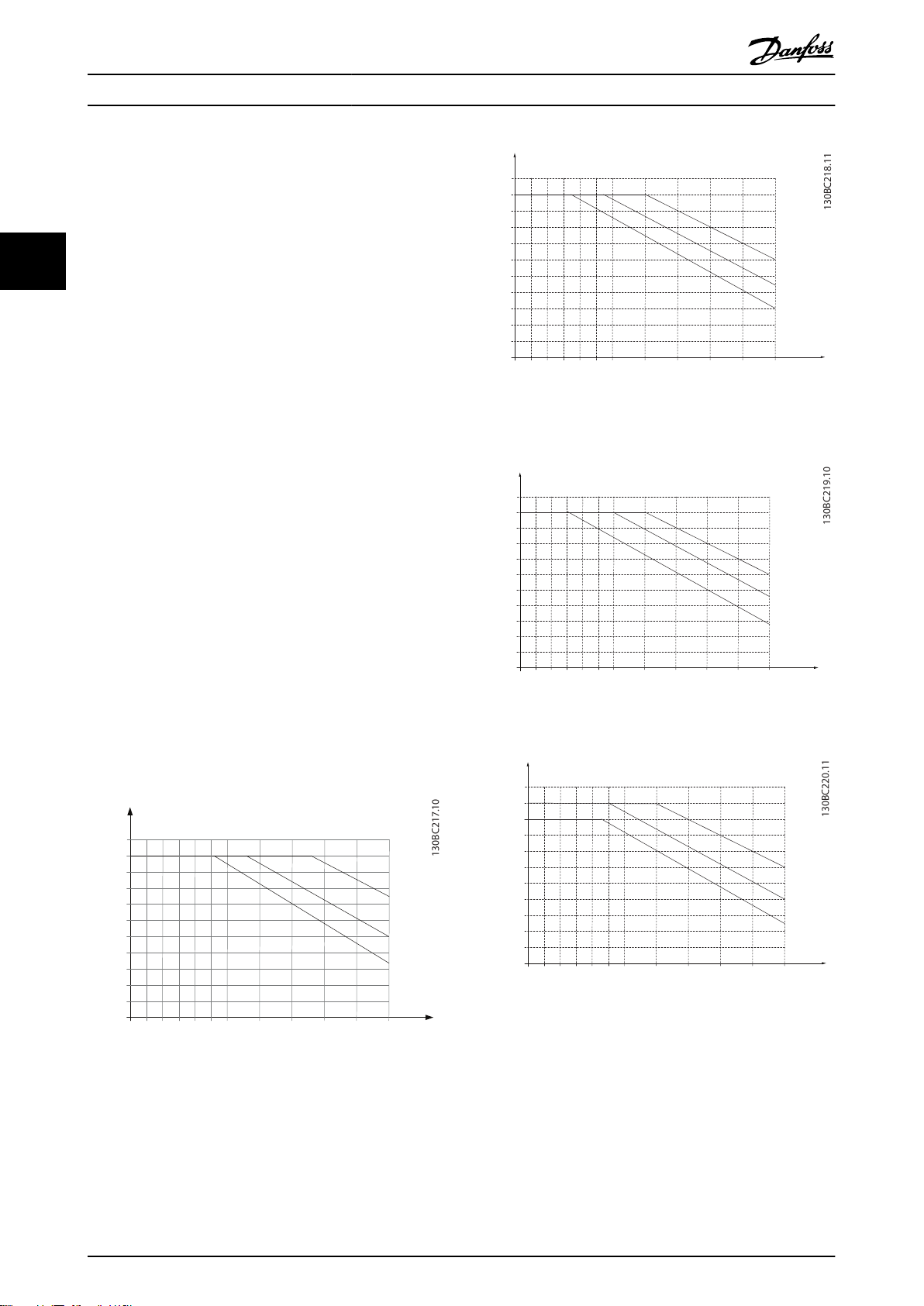
图 3.23 0.37–1.5 kW (0.5–2.0 hp),400 V,机箱规格
H1,IP20
工作环境条件
3.3
变频器在 50 °C (122 °F) 时符合 IEC/EN 60068-2-3、
EN 50178 9.4.2.2 标准。
图 3.24 2.2 kW (3.0 hp),200 V,机箱规格 H2,IP20
在 24 小时内测量的环境温度至少要比最高环境温度低
5 °C (41 °F)。如果变频器在较高的环境温度下工作,请
降低其持续输出电流。
图 3.25 2.2–4.0 kW (3.0–5.4 hp),400 V,机箱规格
H2,IP20
图 3.22 0.25–0.75 kW (0.34–1.0 hp),200 V,机箱规格
H1,IP20
28 Danfoss A/S © 04/2018 全权所有。 MG18C841
Page 31

fsw[kHz]
20 10
0
10%
20%
30%
40%
50%
60%
70%
80%
90%
100%
110%
I
out
[%]
16
40
45
50
5
o
C
o
C
o
C
130BC221.10
fsw[kHz]
20 10
0
10%
20%
30%
40%
50%
60%
70%
80%
90%
100%
110 %
I
out
[%]
16
5
40
45
50
o
C
o
C
o
C
104 oF
113 oF
122 oF
fsw[kHz]
20 10
0
10%
20%
30%
40%
50%
60%
70%
80%
90%
100%
110%
I
out
[%]
16
40
45
50
5
o
C
o
C
o
C
130BC223.10
fsw[kHz]
20 10
0
10%
20%
30%
40%
50%
60%
70%
80%
90%
100%
110%
I
out
[%]
16
40
45
50
5
o
C
o
C
o
C
130BC224.10
fsw[kHz]
20 10
0
10%
20%
30%
40%
50%
60%
70%
80%
90%
100%
110%
I
out
[%]
16
40
45
50
5
o
C
o
C
o
C
fsw[kHz]
20 10
0
10%
20%
30%
40%
50%
60%
70%
80%
90%
100%
110%
I
out
[%]
16
40
45
50
5
o
C
o
C
o
C
130BC226.10
产品概述 设计指南
3 3
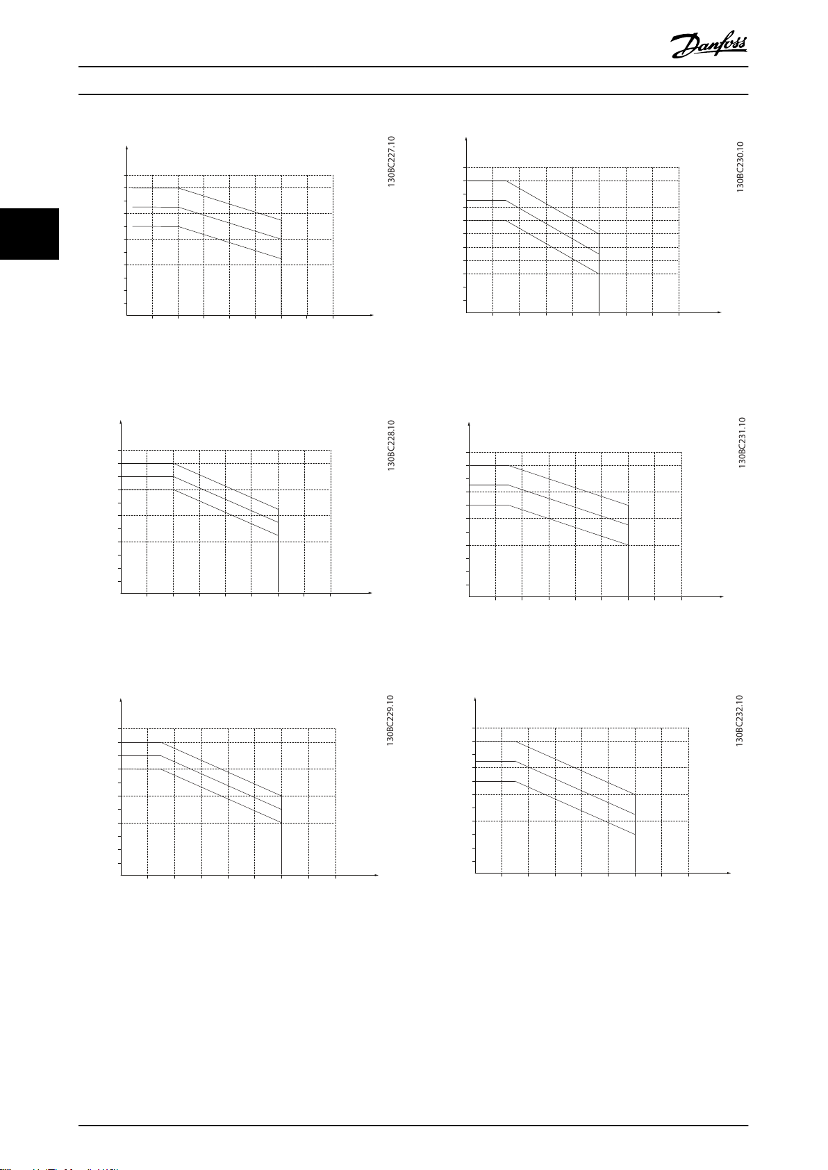
图 3.26 3.7 kW (5.0 hp),200 V,机箱规格 H3,IP20
图 3.27 5.5–7.5 kW (7.4–10 hp),400 V,机箱规格 H3,
IP20
图 3.29 11–15 kW (15–20 hp),400 V,机箱规格 H4,
IP20
图 3.30 11 kW (15 hp),200 V,机箱规格 H5,IP20
图 3.28 5.5–7.5 kW (7.4–10 hp),200 V,机箱规格 H4,
IP20
MG18C841 Danfoss A/S © 04/2018 全权所有。 29
图 3.31 18.5–22 kW (25–30 hp),400 V,机箱规格 H5,
IP20
Page 32
I
out
[%]
f
sw
[kHz]
20
%
2 4 6 8 10 12
40
%
60
%
80
%
40
o
C
45
o
C
50
o
C
100
%
110
%
I
out
[%]
f
sw
[
kHz
]
20
%
2 4 6 8 10 12
40
%
60
%
80
%
40oC
45
o
C
50
o
C
100
%
110
%
I
out
[%]
f
sw
[kHz]
20
%
2 4 6 8 10 12
40
%
60
%
80
%
40oC
45
o
C
50
o
C
100
%
110
%
130BC229.10
I
out
[%]
f
sw
[kHz]
20
%
2 4 6 8 10 12
40
%
60
%
80
%
40oC
45
o
C
50
o
C
100
%
110
%
I
out
[%]
fsw [kHz]
20
%
2 4 6 8 10 12
40
%
60
%
80
%
40oC
45
o
C
50
o
C
100
%
110
%
I
out
[%]
f
sw
[kHz]
20
%
2 4 6 8 10 12
40
%
60
%
80
%
40oC
45
o
C
50
o
C
100
%
110
%
产品概述
VLT® HVAC Basic Drive FC 101
33
图 3.32 15–18.5 kW (20–25 hp),200 V,机箱规格 H6,
IP20
图 3.33 30–37 kW (40–50 hp),400 V,机箱规格 H6,
IP20
图 3.35 22–30 kW (30–40 hp),600 V,机箱规格 H6,
IP20
图 3.36 22–30 kW (30–40 hp),200 V,机箱规格 H7,
IP20
图 3.34 45 kW (60 hp),400 V,机箱规格 H6,IP20
图 3.37 55–75 kW (74–100 hp),400 V,机箱规格 H7,
IP20
30 Danfoss A/S © 04/2018 全权所有。 MG18C841
Page 33

I
out
[%]
f
sw
[kHz]
20
%
2 4 6 8 10 12
40
%
60
%
80
%
40oC
45
o
C
50
o
C
100
%
110
%
I
out
[%]
f
sw
[kHz]
20
%
2 4 6 8 10 12
40
%
60
%
80
%
40
o
C
45
o
C
50
o
C
100
%
110
%
I
out
[%]
f
sw
[kHz]
20 %
2 4 6 8 10 12
40 %
60 %
80 %
40oC
45
o
C
50
o
C
100 %
110 %
130BC235.10
I
out
[%]
f
sw
[kHz]
20
%
2 4 6 8 10 12
40
%
60
%
80
%
40
o
C
45
o
C
50
o
C
100
%
110
%
130BC236.10
I
out
[%]
f
sw
[kHz]
20
%
2 4 6 8 10 12
40
%
60
%
80
%
40oC
45
o
C
50
o
C
100
%
110
%
130BC237.10
I
out
[%]
f
sw
[kHz]
20
%
2 4 6 8 10 12
40
%
60
%
80
%
40oC
45
o
C
50
o
C
100
%
110
%
产品概述 设计指南
3 3
图 3.38 45–55 kW (60–74 hp),600 V,机箱规格 H7,
IP20
图 3.39 37–45 kW (50–60 hp),200 V,机箱规格 H8,
IP20
图 3.41 75–90 kW (100–120 hp),600 V,机箱规格 H8,
IP20
图 3.42 2.2–3 kW (3.0–4.0 hp),600 V,机箱规格 H9,
IP20
图 3.40 90 kW (120 hp),400 V,机箱规格 H8,IP20
图 3.43 5.5–7.5 kW (7.4–10 hp),600 V,机箱规格 H9,
IP20
MG18C841 Danfoss A/S © 04/2018 全权所有。 31
Page 34

I
out
[%]
f
sw
[kHz]
20
%
2 4 6 8 10 12
40
%
60
%
80
%
40oC
45
o
C
50
o
C
100
%
110
%
fsw[kHz]
20 10
0
10%
20%
30%
40%
50%
60%
70%
80%
90%
100%
110%
I
out
[%]
16
40
45
50
5
o
C
o
C
o
C
130BC255.10
fsw[kHz]
20 10
0
10%
20%
30%
40%
50%
60%
70%
80%
90%
100%
110%
I
out
[%]
16
40
45
50
5
o
C
o
C
o
C
130BC256.10
130BD012.10
o
70%
80%
90%
0
I [%]
out
60%
100%
110%
2 84106
50 C
50%
40%
30%
20%
10%
0
o
40 C
12 14 16
fsw[kHz]
Iout [%]
f
sw [kHz]
20
%
2 4 6 8 10 12
40
%
60
%
80
%
40oC
45
o
C
50
o
C
100
%
110
%
130BC240.10
Iout [%]
f
sw [kHz]
20
%
2 4 6 8 10 12
40
%
60
%
80
%
40
o
C
45
o
C
50
o
C
100
%
110
%
130BC241.10
产品概述
VLT® HVAC Basic Drive FC 101
33
图 3.44 11–15 kW (15–20 hp),600 V,机箱规格 H10,
IP20
图 3.47 11–18.5 kW (15–25 hp),400 V,机箱规格 I4,
IP54
图 3.45 0.75–4.0 kW (1.0–5.4 hp),400 V,机箱规格
I2,IP54
图 3.48 22–30 kW (30–40 hp),400 V,机箱规格 I6,
IP54
图 3.46 5.5–7.5 kW (7.4–10 hp),400 V,机箱规格 I3,
IP54
32 Danfoss A/S © 04/2018 全权所有。 MG18C841
图 3.49 37 kW (50 hp),400 V,机箱规格 I6,IP54
Page 35

Iout [%]
f
sw [kHz]
20
%
2 4 6 8 10 12
40
%
60
%
80
%
40oC
45
o
C
50
o
C
100
%
110
%
Iout [%]
f
sw [kHz]
20
%
2 4 6 8 10 12
40
%
60
%
80
%
40oC
45
o
C
50
o
C
100
%
110
%
130BC243.10
产品概述 设计指南
图 3.50 45–55 kW (60–74 hp),400 V,机箱规格 I7,
IP54
机箱规格
H8 73.5
H9 60
H10 62.9
I2 50.2
I3 54
I4 67.4
I6 70
I7 62
I8 65.6
表 3.3 在距离设备
1 米(3.28 英尺)处测得的典型值
级别 [dBA]
1)
1) 这些值是在 35 dBA 噪音背景下且风扇全速运行时测得的
值。
变频器已按照 中所列标准中规定的步骤进行测试,
表 3.4
。
变频器满足以下安装条件,即在厂房的墙壁或地面上,以
及在固定到墙壁或地面上的面板中安装。
IEC/EN 60068-2-6 振动(正弦) - 1970
IEC/EN 60068-2-64 宽带随机振动
3 3
表 3.4 标准
变频器含有许多机械和电子元件。它们或多或少都会受到
环境的影响。
图 3.51 75–90 kW (100–120 hp),400 V,机箱规格 I8,
IP54
小心
安装环境
如果电机或电机驱动的设备(如风扇)会在特定频率时发
出噪音或出现振动,请配置以下参数或参数组,以降低或
消除噪音/振动:
参数组 4-6* 频率跳越
•
将
•
•
参数 14-03 超调
在
参数组 14-0* 逆变器开关
。
设置为
[0]
关闭。
中更改模式和开关
频率。
参数 1-64 共振衰减
•
.
变频器的声源性噪音有 3 个来源:
直流回路线圈。
•
内置风扇。
•
射频干扰滤波器的扼流装置。
•
机箱规格
H1 43.6
H2 50.2
H3 53.8
H4 64
H5 63.7
H6 71.5
H7 67.5 (75 kW (100 hp) 71.5 dB)
MG18C841 Danfoss A/S © 04/2018 全权所有。 33
级别 [dBA]
1)
不能将变频器安装在带有空气传播的液体、颗粒或气体的
环境中,以免影响或损坏电子元件。若不采取必要的保护
措施,则会增加停机风险,并可能导致设备损坏和人身伤
害。
液体会通过空气传播并在变频器中冷凝,这可能导致元件
和金属部件发生腐蚀。蒸汽、油和盐水也会腐蚀元件和金
属部件。在这样的环境中,设备应采用 IP54 级别的机
箱。为了增强保护能力,您可以订购作为选件的带涂层印
刷电路板(在某些功率规格上为标配)。
空气传播的颗粒(如尘粒)可能导致变频器出现机械、电
子或热故障。如果变频器的风扇周围存在尘粒,通常可以
说明空气传播的颗粒超标。在多尘环境中,设备应采用
IP54 级别的机箱或用于 IP20/类型 1 设备的机柜。
在温度和湿度较高的环境中,腐蚀性气体(如硫磺、氮和
氯化物)会导致变频器元件发生化学反应。
这些化学反应会快速腐蚀和损坏电子元件。对于这种环
境,请将设备安装在通风良好的机柜中,使变频器远离腐
蚀性气体。
Page 36

1
2
z
z
z
L1
L2
L3
PE
U
V
W
C
S
I
2
I
1
I
3
I
4
C
S
C
S
C
S
C
S
I
4
C
S
z
PE
3
4
5
6
175ZA062.12
产品概述
VLT® HVAC Basic Drive FC 101
为了增强在这些区域中的保护能力,您可以订购作为选件
的带涂层印刷电路板。
不对泄漏电流进行滤波,它将在主电源上对 5 MHz 左右
以下的无线电频率范围产生更大的干扰。由于泄漏电流
(I1) 会通过屏蔽丝网电流 (I3) 返回设备,根据
安装变频器之前,首先应检查环境空气中是否存在液体、
颗粒和气体。通过观察这种环境中的现有设备,可达到上
图 3.52
(I4) 。
,屏蔽的电动机电缆仅产生一个微弱的电磁场
述目的。金属部件上是否有水或油,或金属零件是否已腐
33
蚀,通常可表明是否存在有害的空气传播液体。
屏蔽丝网降低了辐射性干扰,但增强了主电源的低频干
扰。将电动机电缆的屏蔽丝网同时连接到变频器机箱和电
通过查看现有的设备机柜和电气设备,可以了解尘粒是否
超标。存在腐蚀性气体的一个表现是,现有设备上的铜导
轨和电缆尾部将变暗。
动机的机箱。此时最好使用整体性的屏蔽丝网夹,以避免
屏蔽丝网端部纽结(辫子状)。辫状屏蔽丝网端部纽结会
增加屏蔽丝网在高频下的阻抗,从而降低屏蔽效果并增大
泄漏电流 (I4)。
3.4 关于 EMC 的一般问题
3.4.1 EMC 辐射概述
变频器(和其他电气设备)可生成干扰其环境的电场或磁
场。这些影响的感此兼容性 (EMC) 取决于设备的功率和
谐波特性。
系统中电气设备之间的不受控交互作用可降低兼容性和影
响可靠性操作。干扰可能导致主电源谐波失真、静电放
电、电压快速波动或高频干扰。电气设备可生成干扰,同
时受到其他生成源的干扰。
如果将屏蔽电缆用于继电器、控制电缆、信号接口和制
动,则将屏蔽丝网同时连接到机箱的两端。但有时为了避
免电流回路,也可能需要断开屏蔽丝网。
如果要将屏蔽丝网置于变频器的固定板上,该固定板必须
由金属制成,以将屏蔽丝网电流带回设备。另外,还应确
保从固定板到固定螺钉以及变频器机架都有良好的电气接
触。
在使用无屏蔽电缆时,尽管可能符合安全性要求,但却不
符合某些辐射要求。
系统通常会产生 150 kHz 到 30 MHz 频率范围内的电气
干扰。在变频器系统中,逆变器、电动机电缆和电动机会
产生 30 MHz 到 1 GHz 范围的空中干扰。
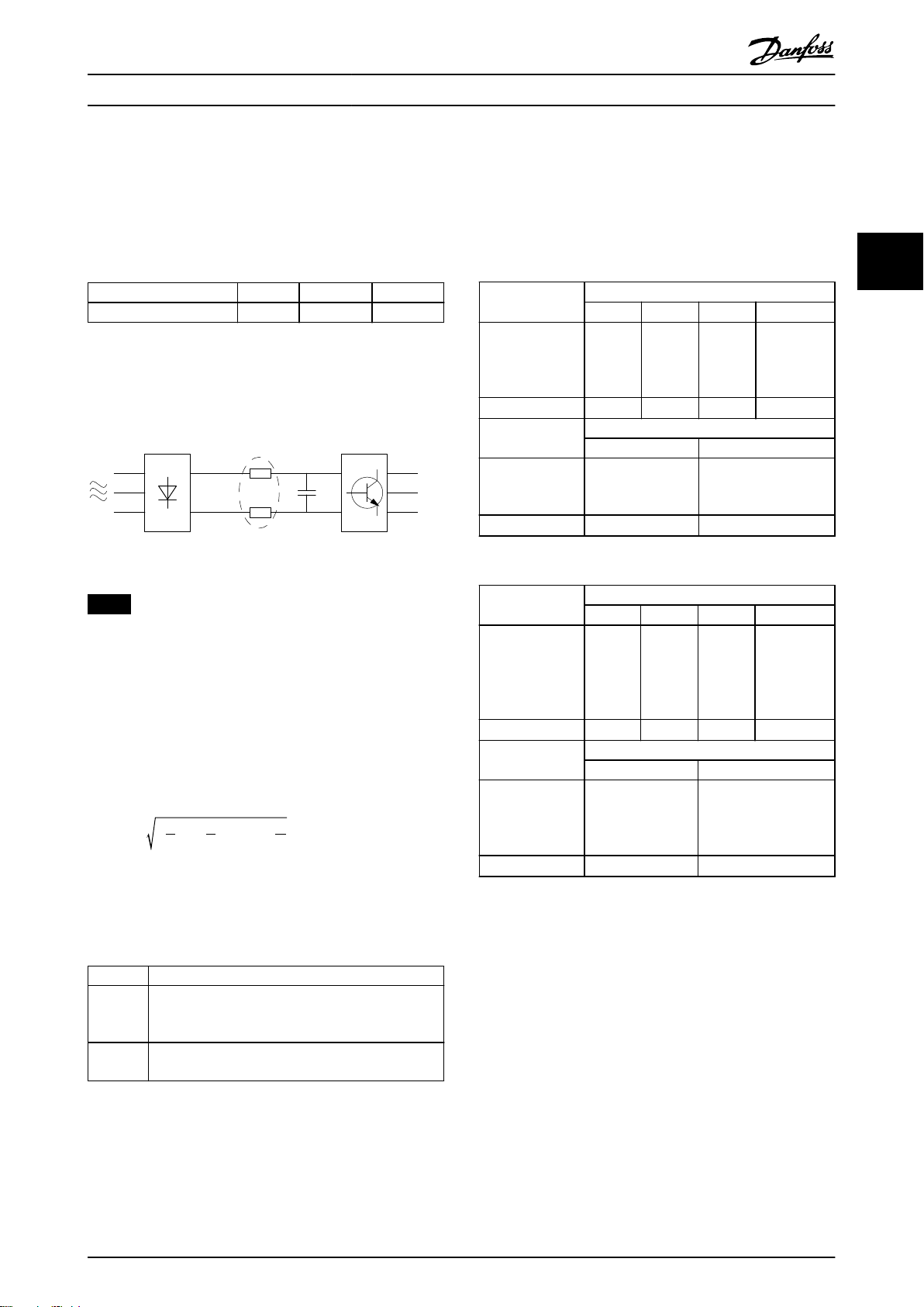
电动机电缆中的电容性电流与电动机的高 dU/dt 特性一
起产生了泄漏电流,如
使用屏蔽电机电缆会增大泄漏电流(请参阅
图 3.52
所示。
图 3.52
),
为了尽量降低整个系统(设备 + 安装)的干扰水平,请
使用尽可能短的电动机电缆和制动电缆。不要将传送敏感
信号电平的电缆与电动机电缆和制动电缆放在一起。控制
性电子元件尤其可能产生 50 MHz 以上的无线电干扰(空
中干扰)。
因为与非屏蔽电缆相比,屏蔽电缆的对地电容更高。如果
1 地线 2 防护罩 3 交流主电源
4 变频器 5 屏蔽电机电缆 6 电动机
图 3.52 产生漏电电流
34 Danfoss A/S © 04/2018 全权所有。 MG18C841
Page 37

产品概述 设计指南
3.4.2 辐射要求
用于变频器的 EMC 产品标准定义了 4 个类别(C1、C2、
C3 和 C4)以及对辐射和抗扰度的规定要求。
明了 4 个类别的定义以及 EN55011 的同等分类。
表 3.5
说
EN/IEC
61800-3
类别
安装在第一种环境中(家庭和办公
C1
室,供电电压低于 1000 V )的
变频器。
安装在第一种环境中(家庭和办公
室,供电电压低于 1000 V )的
C2
变频器,并且不可插拔也不可移
动,只应由专业人员进行安装和调
试。
安装在第二种环境中(工业,供电
C3
电压低于 1000 V )的变频器。
安装在第二种环境中(供电电压等
于或高于 1000 V,或额定电流等
C4
于或高于 400 A )的变频器或要
用于复杂系统的变频器。
表 3.5 IEC61800-3 与 EN 55011 之间的相关性
定义
EN 55011 中的
同等辐射类别
B 类
A 类组 1
A 类组 2
无极限线缆。
制订 EMC 计
划。
使用一般(传导)辐射标准时,变频器需要符合
中的限制。
环境
第一种环境
(家庭和办公
室)
第二种环境
(工业环境)
一般辐射
标准
针对居住、商业和轻工业环
境的 EN/IEC 61000-6-3
辐射标准。
针对工业环境的 EN/IEC
61000-6-4 辐射标准。
EN 55011 中的
同等辐射类别
B 类
A 类组 1
3 3
表 3.6
表 3.6 一般辐射标准和 EN 55011 之间的关联
MG18C841 Danfoss A/S © 04/2018 全权所有。 35
Page 38

产品概述
VLT® HVAC Basic Drive FC 101
3.4.3 EMC 辐射测试结果
下列测试结果是使用由变频器、屏蔽控制电缆、控制箱(带电位计)以及屏蔽电机电缆组成的系统获得的。
射频干扰滤波器类
33
EN 55011 之间的相
H4 射频干扰滤波器 (EN55011 A1, EN/IEC61800-3 C2)
0.25–11 kW
(0.34–15 hp)
3x200–240 V IP20
0.37–22 kW
(0.5–30 hp)
3x380–480 V IP20
H2 射频干扰滤波器 (EN 55011 A2, EN/IEC 61800-3 C3)
15–45 kW
(20–60 hp)
3x200–240 V IP20
30–90 kW
(40–120 hp)
3x380–480 V IP20
0.75–18.5 kW
(1–25 hp)
3x380–480 V IP54
22–90 kW
(30–120 hp)
3x380–480 V IP54
H3 射频干扰滤波器 (EN55011 A1/B, EN/IEC 61800-3 C2/C1)
15–45 kW
(20–60 hp)
3x200–240 V IP20
30–90 kW
(40–120 hp)
3x380–480 V IP20
0.75–18.5 kW
(1–25 hp)
3x380–480 V IP54
22–90 kW
(30–120 hp)
3x380–480 V IP54
型
工业环境
A 类组 2
关性
EN/IEC 61800-3
工业环境
类别 C3
次要环境
无外部滤波器有外部
– – 25 (82) 50 (164) – 20 (66) 是 是 – 否
– – 25 (82) 50 (164) – 20 (66) 是 是 – 否
25 (82) – – – – – 否 – 否 –
25 (82) – – – – – 否 – 否 –
25 (82) – – – – – 是 – – –
25 (82) – – – – – 否 – 否 –
– – 50 (164) – 20 (66) – 是 – 否 –
– – 50 (164) – 20 (66) – 是 – 否 –
– – 25 (82) – 10 (33) – 是 – – –
– – 25 (82) – 10 (33) – 是 – 否 –
传导性干扰。屏蔽电缆最大长度 [m (ft)] 辐射性干扰
工业
A 类组 1
工业环境
类别 C2
主要环境
家庭和办公室
无外部滤波器有外部滤波器无外部滤波器有外部滤波器无外部
滤波器
B 类
住宅、商业与轻工业
类别 C1
主要环境
家庭和办公室
A 类组 1
工业环境
类别 C2
主要环境
家庭和办公室
滤波器
有外部
滤波器
B 类
住宅、商业与轻
工业
类别 C1
主要环境
家庭和办公室
无外部
滤波器
有外部
滤波器
表 3.7 EMC 辐射测试结果
36 Danfoss A/S © 04/2018 全权所有。 MG18C841
Page 39
175HA034.10
产品概述 设计指南
3.4.4 谐波辐射概述
变频器从主电源获得非正弦电流,这使得输入电流 I
增加。可利用傅里叶分析对非正弦电流进行转换,将其分
为具有不同频率的正弦波电流,即基本频率为 50 Hz 的
不同谐波电流 In:
I
Hz 50 250 350
表 3.8 谐波电流
1
I
5
谐波电流并不直接影响功耗,但可增大设备(变压器、电
缆)的热损耗。如果设备的整流器负载百分比较高,则应
使谐波电流尽可能低,以避免变压器过载和电缆过热。
图 3.53 直流回路线圈
RMS
I
7
注意
某些谐波电流可能会干扰与同一个变压器相连的通讯设
备,或导致与使用功率因数修正电池有关的共振。
为了保证谐波电流较低,变频器标配有直流回路线圈。这
通常可以使输入电流 I
主电源电压失真取决于谐波电流与所用频率下的主电源阻
抗的乘积。可借助下列公式根据各个电压谐波计算总电压
失真 THD:
2
U
THD % =
5
+ U
(U 的 UN%)
RMS
2
+ ... + U
7
降低 40%。
2
N
3.4.6 谐波测试结果(辐射)
T4 中不超过 PK75 和 T2 中不超过 P3K7 的功率规格符
合 IEC/EN 61000-3-2 A 类标准。T2 中从 P1K1 到小于
等于 P18K 以及 T4 中小于等于 P90K 的功率规格符合
IEC/EN 61000-3-12 标准,见表 4。
实际 0.25-11kW
(0.34–15 hp),
IP20,200 V(典
型)
R
极限 ≥120
sce
实际 0.25-11kW
(0.34–15 hp),
200 V(典型)
R
极限 ≥120
sce
表 3.10 谐波电流 0.25–11 kW (0.34–15 hp),200 V
实际 0.37–22
kW (0.5–30
hp),IP20,
380–480 V(典
型)
R
极限 ≥120
sce
实际 0.37–22
kW (0.5–30
hp),380–480 V
(典型)
R
极限 ≥120
sce
各个谐波电流 In/I1 (%)
I
5
32.6 16.6 8.0 6.0
40 25 15 10
I
5
36.7 20.8 7.6 6.4
40 25 15 10
I
7
谐波电流失真因数 (%)
THDi PWHD
39 41.4
48 46
各个谐波电流 In/I1 (%)
I
7
谐波电流失真因数 (%)
THDi PWHD
44.4 40.8
48 46
I
11
I
11
I
I
13
13
3 3
3.4.5 谐波辐射要求
表 3.11 谐波电流 0.37–22 kW (0.5–30 hp),380-480 V
连接到公共供电网络的设备
选件 定义
IEC/EN 61000-3-2 A 类标准,对于三相平衡设备
1
(仅适用于总功率不超过 1 kW (1.3 hp) 的专业设
备)。
IEC/EN 61000-3-12 16 A-75 A 设备以及从 1 kW
2
(1.3 hp) 到相电流不超过 16 A 的专业设备。
表 3.9 连接的设备
MG18C841 Danfoss A/S © 04/2018 全权所有。 37
Page 40

产品概述
VLT® HVAC Basic Drive FC 101
实际 30–90 kW
(40–120 hp),
IP20,380–480
V(典型)
33
R
极限 ≥120
sce
实际 30–90 kW
(40–120 hp),
380–480 V(典
型)
R
极限 ≥120
sce
各个谐波电流 In/I1 (%)
I
5
I
7
I
11
I
36.7 13.8 6.9 4.2
40 25 15 10
谐波电流失真因数 (%)
THDi PWHD
40.6 28.8
48 46
13
实际 22–90 kW
(30–120 hp),
IP54,400 V(典
型)
R
实际 22–90 kW
(30–120 hp),
IP54 400 V(典
型)
R
表 3.12 谐波电流 30–90 kW (40–120 hp),380–480 V
实际 2.2–15 kW
(3.0–20 hp),
IP20,525–600
V(典型)
实际 2.2–15 kW
(3.0–20 hp),
525–600 V(典
型)
表 3.13 谐波电流 2.2–15 kW (3.0–20 hp), 525–600 V
各个谐波电流 In/I1 (%)
I
5
I
7
I
11
48 25 7 5
谐波电流失真因数 (%)
THDi PWHD
55 27
各个谐波电流 In/I1 (%)
I
5
I
7
I
11
I
13
实际 0.75–18.5
kW (1.0–25
hp),IP54,
380-480 V(典
型)
R
实际 0.75–18.5
kW (1.0–25
hp),IP54,
380–480 V(典
型)
I
13
R
实际 18.5–90
极限 ≥120
sce
极限 ≥120
sce
表 3.15 谐波电流 22–90 kW (30–120 hp),400 V
极限 ≥120
sce
极限 ≥120
sce
表 3.16 谐波电流 0.75–18.5 kW (1.0–25 hp),380–480 V
各个谐波电流 In/I1 (%)
I
5
I
7
I
11
I
36.3 14 7 4.3
40 25 15 10
谐波电流失真因数 (%)
THDi PWHD
40.1 27.1
48 46
各个谐波电流 In/I1 (%)
I
5
I
7
I
11
I
36.7 20.8 7.6 6.4
40 25 15 10
谐波电流失真因数 (%)
THDi PWHD
44.4 40.8
48 46
13
13
kW (25–120
hp),IP20,
525–600 V(典
型)
实际 18.5–90
kW (25–120
hp),525–600 V
(典型)
表 3.14 谐波电流 18.5–90 kW (25–120 hp),525–600 V
48.8 24.7 6.3 5
谐波电流失真因数 (%)
THDi PWHD
55.7 25.3
实际 15–45 kW
(20–60 hp),
IP20,200 V(典
型)
R
极限 ≥120
sce
实际 15–45 kW
(20–60 hp),
各个谐波电流 In/I1 (%)
I
5
I
7
I
11
26.7 9.7 7.7 5
40 25 15 10
谐波电流失真因数 (%)
THDi PWHD
30.3 27.6
I
13
200 V(典型)
R
极限 ≥120
sce
48 46
表 3.17 谐波电流 15–45 kW (20–60 hp),200 V
38 Danfoss A/S © 04/2018 全权所有。 MG18C841
Page 41
SMPS
130BB896.10
1
2
3
a
M
130BB901.10
1324
5
a
M
产品概述 设计指南
如果电源 Ssc 的短路功率大于或等于:
S
= 3 × R
SC
SCE
× U
主电源
× I
= 3 × 120 × 400 × I
equ
equ
(用户供电系统和公共供电系统之间的接口点位置
(R
))
sce
设备的安装者或用户应负责确保设备仅与短路功率 Ssc 大
于或等于上述规定值的电源相连。为此请咨询配电网络运
营商(如果必要的话)。
在咨询了配电网络运营商后,可以将其它功率规格连接到
公共供电网络。
符合多种系统级别的指导标准:
表 3.10 至表 3.17
中给出的谐波电流数据符合 IEC/EN
61000-3-12 中的动力驱动系统产品标准。可以基于它们
来计算谐波电流对电源系统的影响,也可以将它们视作符
合相关地区性指导标准的证明: IEEE 519 -1992;
G5/4.
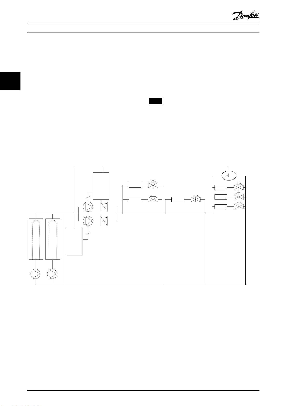
3.4.7 抗扰性要求
变频器的安全性要求取决于它们的安装环境。工业环境的
要求要高于家庭和办公室环境的要求。所有 Danfoss 变
频器均符合工业环境标准,因此也符合较低的、具有较大
安全宽限的家庭和办公室环境要求。
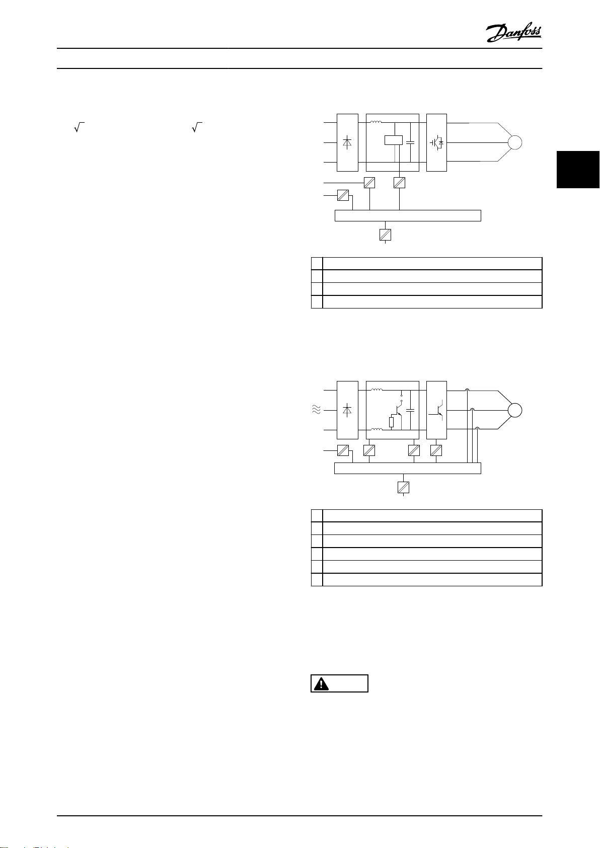
0.25–22 kW (0.34–30 hp)
3 3
1 电源 (SMPS)
2 光学耦合器,AOC 和 BOC 之间的通讯
3 自定义继电器
a 控制卡端子
图 3.54 高低压绝缘
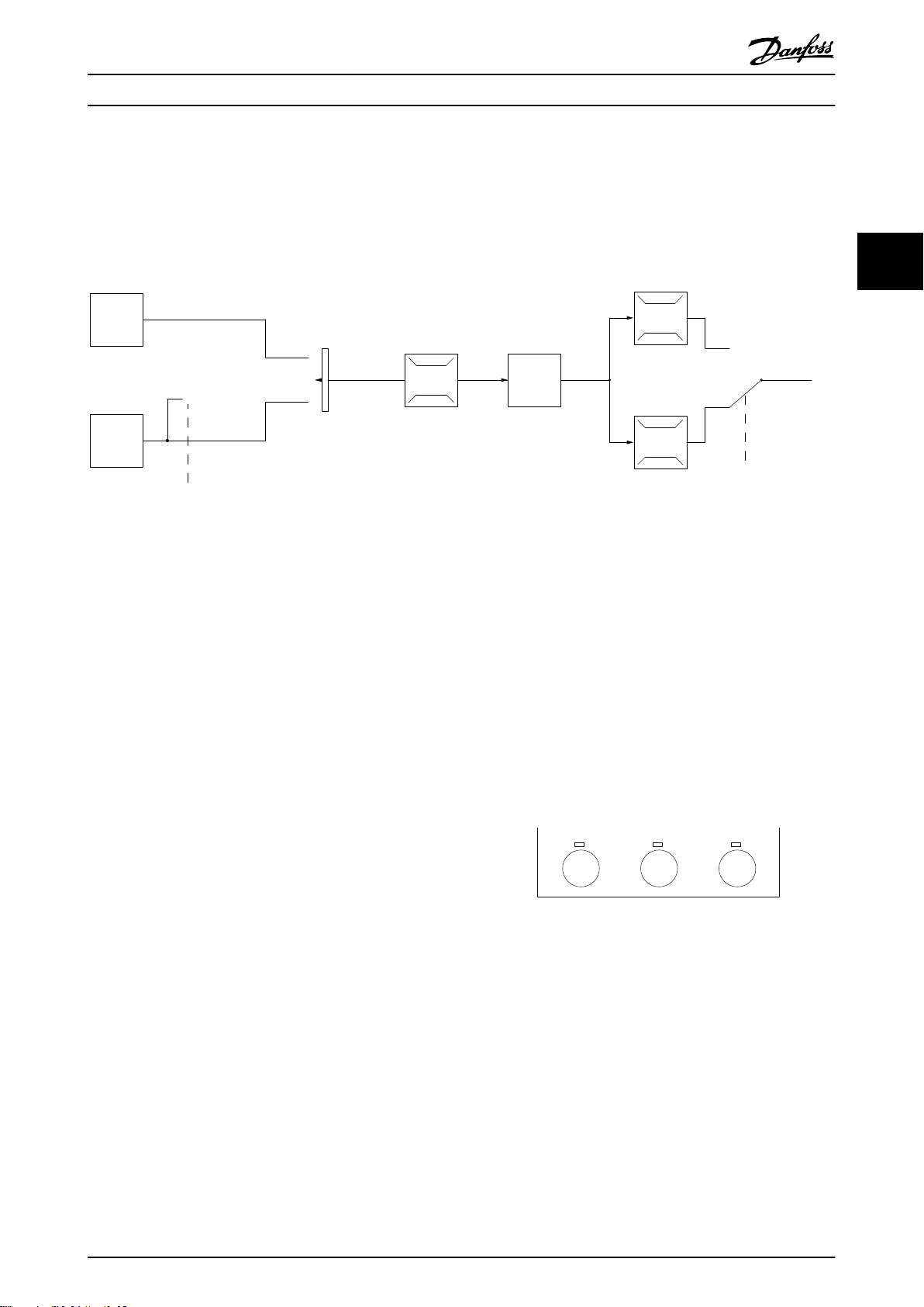
30–90 kW (40–120 hp)
高低压绝缘 (PELV)
3.5
PELV 通过极低电压提供保护 。如果电源为 PELV 类型,
且安装符合地方/国家对 PELV 电源的规定,则可避免发
生触电。
所有控制端子和继电器端子 01-03/04-06 都符合 PELV
(保护性超低压)标准(不适用于 440 V 以上的接地三
角形线路)。
如果能满足较高绝缘要求并保证相应空间间隔,则可以获
得令人满意的流电绝缘效果。EN 61800-5-1 标准对这些
要求进行了专门介绍。
提供电气绝缘的部件(如下所述)也必须满足较高的绝缘
标准并通过 EN 61800-5-1 规定的相关测试。
PELV 流电绝缘主要包括
图 3.55
。
为了保持 PELV,所有与控制端子的连接都必须是 PELV
的,比如,必须对热敏电阻实行加强绝缘/双重绝缘。
1 包括 UDC 信号绝缘的电源 (SMPS),表示中间电流电压
2 驱动 IGBT 的门驱动器(触发变压器和光学耦合器)。
3 电流传感器
4 内部软充电、RFI 和温度测量电路。
5 自定义继电器
a 控制卡端子
图 3.55 高低压绝缘
功能性流电绝缘(请参阅
图 3.54
)适用于 RS-485 标准
总线接口。
小心
安装在高海拔下
当海拔超过 2000 米(6500 英尺)时,请向 Danfoss
咨询 PELV 事宜。
MG18C841 Danfoss A/S © 04/2018 全权所有。 39
Page 42
产品概述
VLT® HVAC Basic Drive FC 101
如果滑移补偿设置(
3.6 接地漏电电流
警告
放电时间
即使设备已断开与主电源的连接,触碰电气部件也可能会
33
导致生命危险。
另外,还需确保所有其他电源输入都已断开,例如负载共
享(直流回路的连接),以及用于借能运行的电动机连
接。
在触摸任何电气部件之前,至少等待
间。
仅当具体设备的铭牌上标明了更短的等待时间时,才允许
缩短等待时间。
表 2.1
中规定的时
•
当,可能导致直流回路的电压升高。
如果启用了
加减速过程。
当达到特定的电压水平时,变频器会关闭,以保护晶体管
和直流回路电容器。
主电源断电
如果发生主电源断电,变频器将继续工作,直到直流回路
电压低于最低停止水平(一般比变频器的最低额定电源电
压低 15%)。断电前的主电源电压和电动机负载决定了变
频器惯性运动的时间。
参数 2-17 过压控制
参数 1-62 滑差补偿
,控制单元会试图更正
) 不
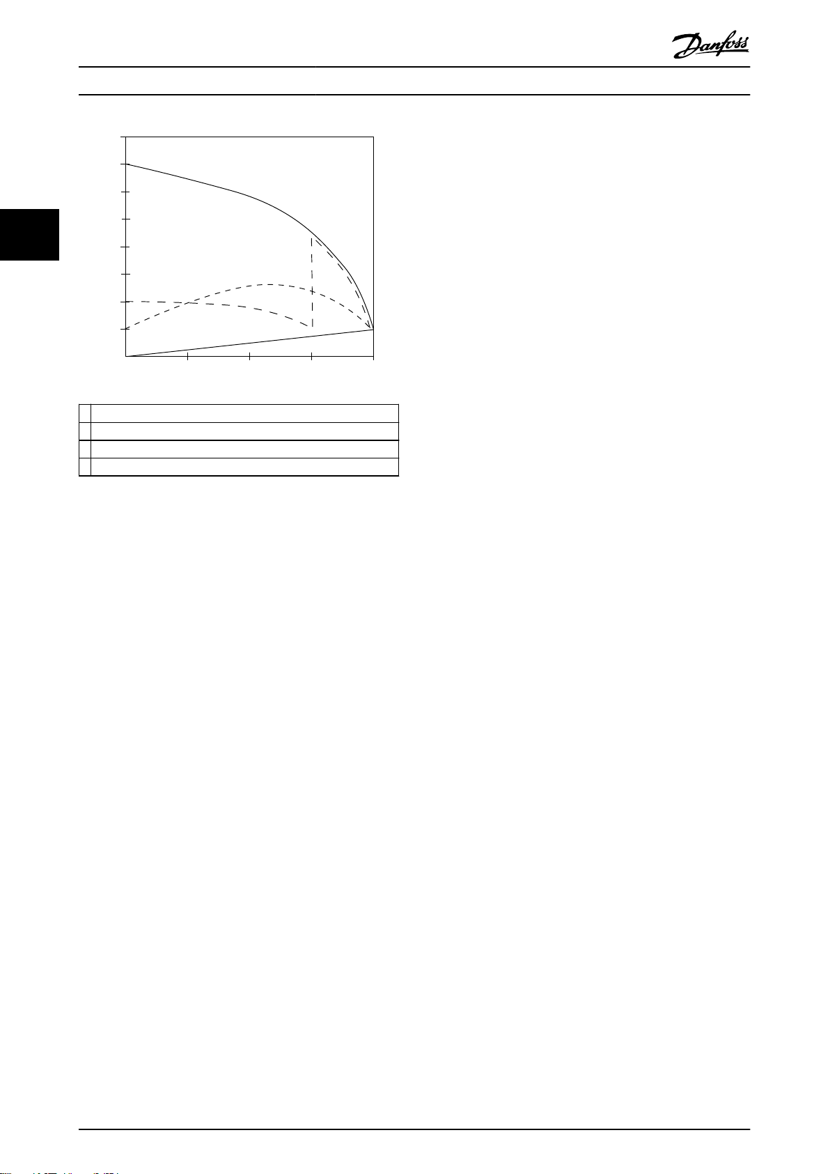
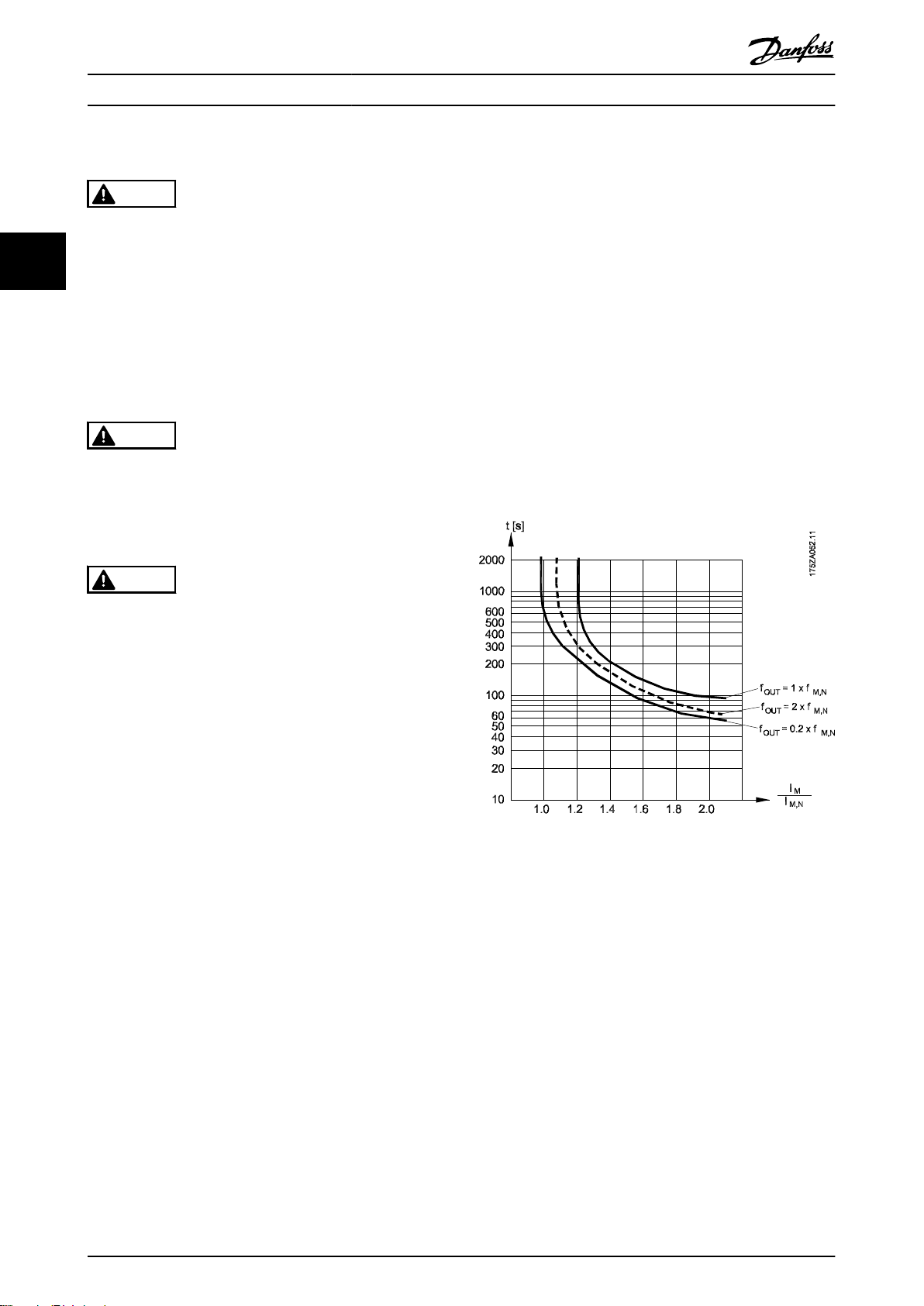
3.7.1 电机热保护 (ETR)
警告
漏电电流危险
漏电电流超过 3.5 mA。如果不将变频器正确接地,将可
能导致死亡或严重伤害。
由经认证的电气安装商确保设备正确接地。
•
Danfoss 使用 ETR 来防止电机过热。它是一种根据内部
测量来模拟双金属继电器的电子功能。其特性如
所示。
图 3.56
警告
漏电断路器保护
该设备可在保护性导体中产生直流电流。当使用漏电断路
器 (RCD) 提供直接或间接接触情况下的保护时,在该设
备的电源端只能使用 B 类 RCD。否则,应采取其它保护
措施,比如用双重或增强绝缘与环境相分隔,或用变压器
将其与供电系统隔开。另请参阅应用说明
变频器的保护性接地和 RCD 的使用必须始终遵从国家和
地方法规。
防范电气危险
。
3.7 极端运行条件
短路(电机相间短路)
测量电机三个相位中每一个相位的电流或者直流回路的电
流,可为变频器提供短路保护。两个输出相位之间产生短
路可导致逆变器过流。当短路电流超过允许的值后,逆变
器将被关闭 (Alarm 16, Trip Lock (报警 16,跳闸锁
定))。
有关在负载共享和制动输出端发生短路时保护变频器的信
息,请参阅
进行输出切换
在电机与变频器之间进行输出切换是允许的。打开输出不
会对变频器造成任何损害。但可能会显示故障信息。
电动机产生过电压
如果电动机用作发电机,则直流回路中的电压会升高。这
包括以下情况:
•
•
章 8.3.1 熔断器和断路器
负载(以变频器的恒定输出频率)驱动电机,即
负载发电。
在减速时,如果惯性力矩较大,则摩擦较小,减
速时间会过短,从而导致变频器、电机和系统无
法消耗掉能量。
。
图 3.56 电机热保护特性
X 轴显示了 I
断开并使变频器跳闸之前的时间(秒)。曲线显示了额定
速度下、2 倍额定速度下以及 0.2 倍额定速度下的特
性。
其中清楚表明,在较低速度下,因为电机的冷却能力降
低,ETR 会在较低热量水平下断开。它以这种方式防止电
动机在低速下过热。ETR 功能根据实际电流和速度计算电
动机温度。
和额定 I
motor
的比。Y 轴显示了 ETR
motor
3.7.2 热敏电阻输入
热敏电阻在阻值大于 >3 kΩ 时自动断开。
在电机内部放置一个热敏电阻(PTC 传感器)可以实现绕
组保护。
40 Danfoss A/S © 04/2018 全权所有。 MG18C841
Page 43

R
关
开
<800 Ω >2.9 kΩ
18
19
12 20 55
27 29 42 45 50 53 54
数字输入
数字输入
数字输入
数字输入
61 68 69
N
P
公共接地
+24V
0/4-20mA 模拟输出/数字输出 0/4-20mA 模拟输出/数字输出
公共模拟输入
数字通讯输入
10V/20mA 输入
10V/20mA 输入
10V 输出
总线终端
关 开
130BB898.10
产品概述 设计指南
电动机保护可以通过一系列的技术来实现:
电动机绕组中的 PTC 传感器。
•
机械热开关(Klixon 类型)。
•
电子热敏继电器 (ETR)。
•
3 3
图 3.57 因电机温度过高而跳闸
数字输入和 10 V 电源的示例
当电机温度过高时,变频器将跳闸。
参数设置:
将
参数 1-90 电机热保护
将
参数 1-93 热敏电阻源
设为
[2] 热敏电阻跳闸
设为 [6] 数字输入 29。
。
图 3.58 数字输入/10 V 电源
模拟输入和 10 V 电源的输入
当电机温度过高时,变频器将跳闸。
参数设置:
参数 1-90 电机热保护
将
将
参数 1-93 热敏电阻源
设为
[2] 热敏电阻跳闸
设为
[1] 模拟输入端 53
。
。
MG18C841 Danfoss A/S © 04/2018 全权所有。 41
Page 44
18
19
12 20 55
27 29 42 45 50 53 54
数字输入
数字输入
数字输入
数字输入
61 68 69
N
P
公共接地
+24V
0/4-20mA 模拟输出/数字输出 0/4-20mA 模拟输出/数字输出
公共模拟输入
数字通讯输入
10V/20mA 输入
10V/20mA 输入
10V 输出
总线终端
关 开
130BB897.10
R
<3.0 kΩ
>2.9 kΩ
关
开
产品概述
VLT® HVAC Basic Drive FC 101
注意
勿将模拟输入端
54
设为参考值源。
33
图 3.59 模拟输入/10 V 电源
输入 供电电压 [V]
数字 10
模拟 10
阈值
断路值 [Ω]
<800⇒2.9 k
<800⇒2.9 k
表 3.18 电源电压
注意
确保所选的供电电压符合所使用的热敏电阻元件的规格。
ETR 在
参数 1-90 电机热保护
中激活。
42 Danfoss A/S © 04/2018 全权所有。 MG18C841
Page 45

F C - P T H
130BB899.10
X S A B CX X X X
1 2 3 4 5 6 7 8 9 10 11 12 13 14 15 16 17 18 19 20 302221 23 272524 26 28 29 31 373635343332 38 39
X0 D
1
1
X
X
X
X X X
X X X
选择和订购 设计指南
4 选择和订购
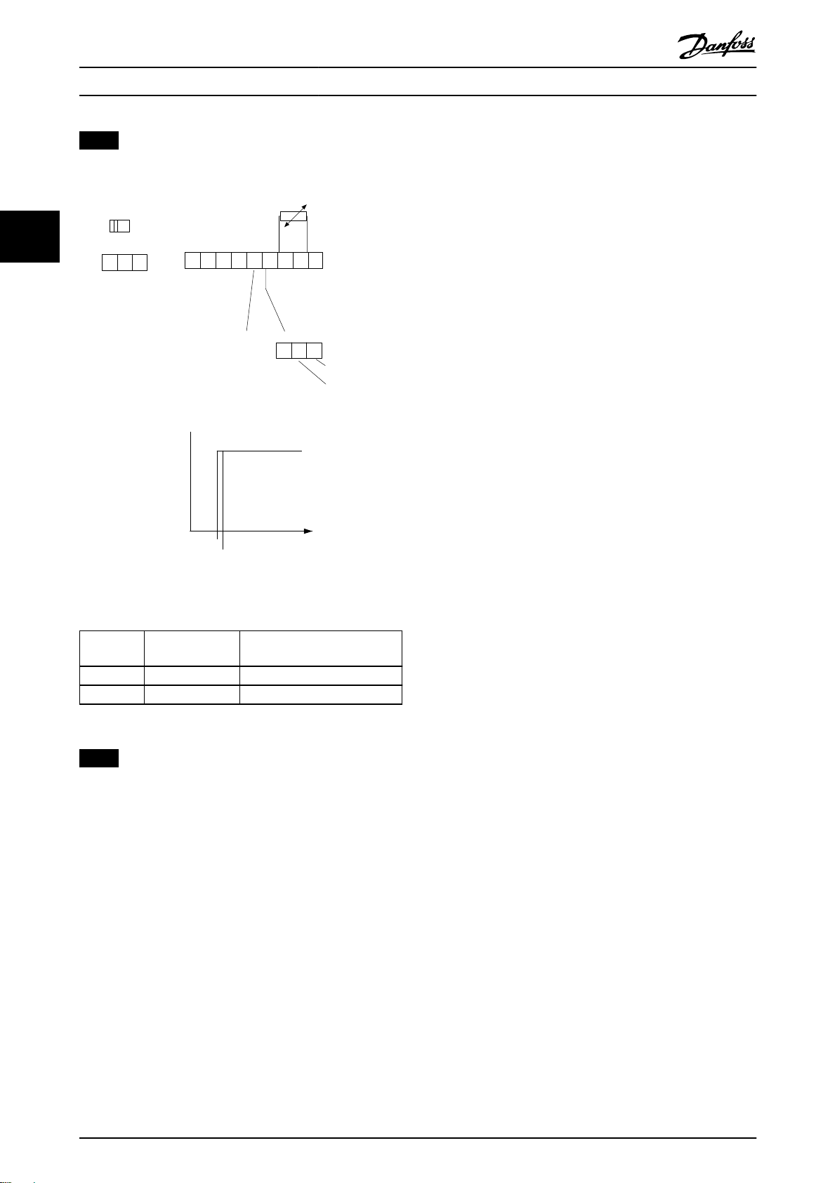
4.1 类型代码
型号代码定义了 VLT® HVAC Basic Drive FC 101 变频器的特定配置。使用
图 4.1 类型代码
说明 位置 可能的选项
产品组 & FC 系列 1–6 FC 101
额定功率 7–10 0.25–90 kW (0.34–120 hp) (PK25-P90K)
相数 11 3 阶段 (T)
T2: 200-240 V AC
主电源电压 11–12
机箱 13–15
RFI 滤波器 16–17
制动 18 X: 不包括制动斩波器
显示 19
涂层 PCB 20
主电源选件 21 X: 无主电源选件
调整 22 X: 无调整
调整 23 X: 无调整
软件版本 24–27 SXXXX: 最新版本的标准软件
软件语言 28 X: 标准型
A 选件 29–30 AX: 无 A 选件
B 选件 31–32 BX: 无 B 选件
C0 选件,MCO 33–34 CX: 无 C 选件
C1 选件 35 X: 无 C1 选件
C 选件软件 36–37 XX: 无选件
D 选件 38–39 DX: 无 D0 选件
T4: 380-480 V AC
T6: 525-600 V AC
E20: IP20/机架
P20: IP20/机架式(带背板)
E5A: IP54
P5A: IP54(带背板)
H1: A1/B 类射频干扰滤波器
H2: A2 类射频干扰滤波器
H3: A1/B 类射频干扰滤波器(电缆长度缩短)
H4: A1 类射频干扰滤波器
A: 字母数字式本地控制面板
X: 无本地控制面板
X: 无涂层 PCB
C: 有涂层 PCB
图 4.1
创建所需配置的型号代码字符串。
4 4
表 4.1 类型代码说明
MG18C841 Danfoss A/S © 04/2018 全权所有。 43
Page 46

130BB775.12
Status
Main
Menu
Quick
Menu
Menu
B
a
c
k
Com.
Status
Main
Menu
Quick
Menu
Hand
On
OK
Menu
O
Reset
Auto
On
Alarm
Warn.
On
Com.
Alarm
Warn.
On
B
a
c
k
Hand
OK
O
Reset
Auto
On On
130BB776.11
R1.5 +_ 0.5
62.5 +_ 0.2
86 +_ 0.2
1
2
3
4
Status
Main
Menu
Quick
Menu
Menu
Com.
Alarm
Warn.
On
Hand
On
OK
O
Reset
Auto
On
B
a
c
k
130BB777.10
选择和订购
4.2 选件和附件
4.2.1 本地控制面板 (LCP)
订购号 说明
132B0200 所有 IP20 设备的 LCP
表 4.2 LCP 的订购号
VLT® HVAC Basic Drive FC 101
44
机箱 IP55 正面安装
与设备的最大电缆长度 3 m (10 ft)
通讯标准 RS485
表 4.3 LCP 的技术数据
4.2.2 将 LCP 安装到面板前方
步骤 1
在 LCP 上安装衬垫。
1 面板切口。面板厚度 1–3 mm (0.04–0.12 in)
2 面板
3 垫圈
4 LCP
图 4.2 安装衬垫
图 4.3 将 LCP 放在面板上(正面安装)
步骤 2
将 LCP 放在面板上,参见
44 Danfoss A/S © 04/2018 全权所有。 MG18C841
图 4.3
中的开孔尺寸。
步骤 3
将托架放在 LCP 背面,然后往下滑。
拧紧螺钉并将电缆带有母接头的一端连接到 LCP。
图 4.4 将托架放在 LCP 上
Page 47

130BB778.10
130BB902.12
A
B
C
OK
Alarm
Warn.
On
B
a
c
k
Hand
On
Reset
Auto
On
Status
Quick
Menu
Main
Menu
130BB903.10
选择和订购 设计指南
步骤 4
将电缆连接到变频器。
4 4
图 4.5 连接电缆
注意
使用所提供的螺纹切削螺钉将接头紧固到变频器上。紧固
力矩为 1.3 Nm (11.5 in-lb)。
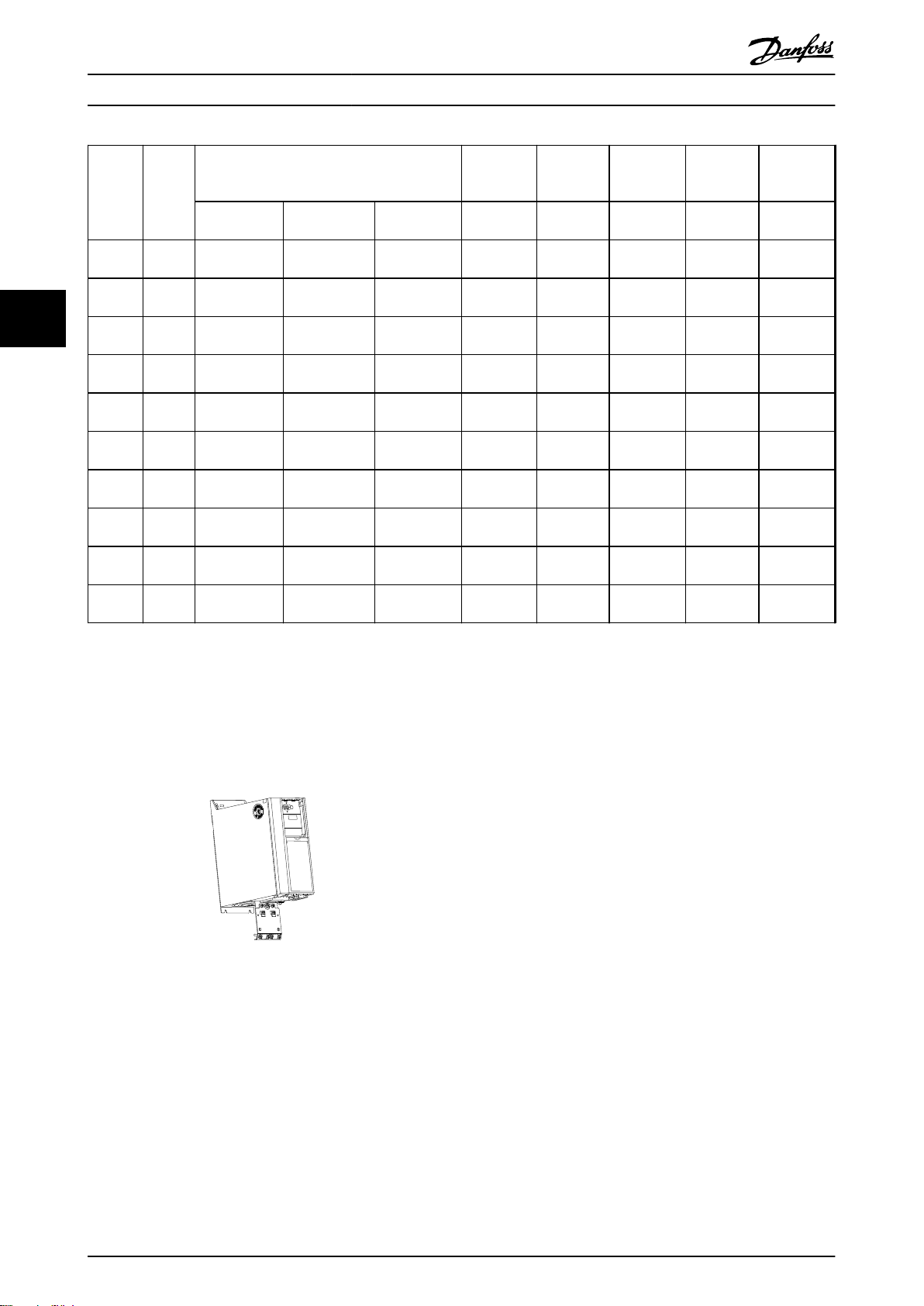
图 4.6 H1–H5(请参阅
表 4.4
中的数据)
4.2.3 IP21/NEMA 类型 1 机箱套件
IP21/NEMA 类型 1 是可选的机箱配件,适用于 IP20 设
备。
通过该机箱套件,可将 IP20 设备的防护级别升级到
IP21/类型 1。
图 4.7 尺寸(请参阅
表 4.4
中的数据)
MG18C841 Danfoss A/S © 04/2018 全权所有。 45
Page 48
130BB793.10
99 99
选择和订购
VLT® HVAC Basic Drive FC 101
高度
功率
机架 IP 等级
3x200–240 V
[kW (hp)]
H1 IP20
H2 IP20 2.2 (3.0)
44
H3 IP20 3.7 (5.0)
H4 IP20
H5 IP20 11 (15)
H6 IP20
H7 IP20
H8 IP20
H9 IP20 – –
H10 IP20 – –
0.25–1.5
(0.34–2.0)
5.5-7.5
(7.4–10)
15–18.5
(20–25)
22–30
(30–40)
37–45
(50–60)
3x380–480 V
[kW (hp)]
0.37–1.5
(0.5–2.0)
2.2-4.0
(3.0–5.4)
5.5-7.5
(7.4–10)
11–15
(15–20)
18.5–22
(25–30)
30–45
(40–60)
55–75
(74–100)
90 (120)
3x525–600 V
[kW (hp)]
– 293 (11.5) 81 (3.2) 173 (6.8) 132B0212 132B0222
– 322 (12.7) 96 (3.8) 195 (7.7) 132B0213 132B0223
– 346 (13.6) 106 (4.2) 210 (8.3) 132B0214 132B0224
– 374 (14.7) 141 (5.6) 245 (9.6) 132B0215 132B0225
– 418 (16.5) 161 (6.3) 260 (10.2) 132B0216 132B0226
18.5–30
(25–40)
37–55
(50–74)
75–90
(100–120)
2.2–7.5
(3.0–10)
11–15
(15–20)
[mm (in)]
A
663 (26.1) 260 (10.2) 242 (9.5) 132B0217 132B0217
807 (31.8) 329 (13.0) 335 (13.2) 132B0218 132B0218
943 (37.1) 390 (15.3) 335 (13.2) 132B0219 132B0219
372 (14.6) 130 (5.1) 205 (8.1) 132B0220 132B0220
475 (18.7) 165 (6.5) 249 (9.8) 132B0221 132B0221
宽度
[mm (in)]
B
深度
[mm (in)]
C
IP21 套件
订购号
NEMA 类型
1 套件订购
号
表 4.4 机箱套件规格
4.2.4 去耦板
使用去耦板可保证系统具有适当的 EMC 抗扰性。
图 4.8
显示出 H3 机箱上的去耦板。
图 4.8 去耦板
46 Danfoss A/S © 04/2018 全权所有。 MG18C841
Page 49

选择和订购 设计指南
功率 [kW(hp)] 去耦板
机架 IP 等级 3x200–240 V 3x380–480 V 3x525–600 V
H1 IP20 0.25–1.5 (0.33–
2.0)
H2 IP20 2.2 (3.0) 2.2–4 (3.0–5.4) – 132B0202
H3 IP20 3.7 (5.0) 5.5–7.5 (7.5–10) – 132B0204
H4 IP20 5.5–7.5 (7.5–10) 11–15 (15–20) – 132B0205
H5 IP20 11 (15) 18.5–22 (25–30) – 130B0205
H6 IP20 15–18.5 (20–25) 30 (40) 18.5–30 (25–40) 132B0207
H6 IP20 – 37–45 (50–60) – 132B0242
H7 IP20 22–30 (30–40) 55 (75) 37–55 (50–75) 132B0208
H7 IP20 – 75 (100) – 132B0243
H8 IP20 37-45 (50–60) 90 (125) 75–90 (100–125) 132B0209
表 4.5 去耦板规格
0.37–1.5 (0.5–
2.0)
– 132B0202
注意
对于机箱规格 H9 和 H10,附件包中包含去耦板。
订购号
4 4
4.3 订购号
4.3.1 选件和附件
机箱规格
说明
1)
LCP
LCP 面板安
装套件,
IP55,含
3 米
(9.8 英
尺)长电缆
LCP 31 至
RJ 45 转换
器套件
主电源电
压
T2
(200-240
V AC)
T4
(380–
480 V
AC)
T6
(525–
600 V
AC)
132B0200
H1
[kW
(hp)]
0.25–
1.5
(0.33–
2.0)
0.37–
1.5
(0.5–
2.0)
– – – – –
H2
[kW
(hp)]
2.2
(3.0)
2.2–4.0
(3.0–
5.4)
H3
[kW
(hp)]
3.7
(5.0)
5.5–7.5
(7.5–
10)
H4
[kW
(hp)]
5.5–7.5
(7.5–
10)
11–15
(15–20)
H5
[kW
(hp)]
11 (15)
18.5–22
(25–30)
132B0201
132B0203
[kW (hp)]
15–18.5
(20–25)
30 (40)
18.5–30
(25–40)
H6
37–45
(50–60)
H7
[kW (hp)]
–
–
22–30
(30–40)
55 (75) 75 (100) 90 (125)
37–55
(50–75)
H8
[kW
(hp)]
–
–
37–45
(50–60)
75–90
(100–
125)
MG18C841 Danfoss A/S © 04/2018 全权所有。 47
Page 50
选择和订购
VLT® HVAC Basic Drive FC 101
机箱规格
LCP 面板安
装套件,
IP55,不含
3 米
(9.8 英
尺)长电缆
44
去耦板 132B0202 132B0202 132B0204 132B0205 132B0205 132B0207 132B0242 132B0208 132B0243 132B0209
IP21 选件 132B0212 132B0213 132B0214 132B0215 132B0216 132B0217 132B0218 132B0219
Nema 类型 1
套件
表 4.6 选件和附件
主电源电
压
H1
[kW
(hp)]
132B0222 132B0223 132B0224 132B0225 132B0226 132B0217 132B0218 132B0219
H2
[kW
(hp)]
H3
[kW
(hp)]
H4
[kW
(hp)]
H5
[kW
(hp)]
132B0206
H6
[kW (hp)]
H7
[kW (hp)]
H8
[kW
(hp)]
1) 对于 IP20 设备,LCP 需单独订购。对于 IP54 设备,LCP 包括在标准配置中,并安装在变频器上。
4.3.2 谐波滤波器
功率
[kW
(hp)]
22
(30)
30
(40)
37
(50)
45
(60)
55
(74)
75
(100)
90
(120)
3x380-480 V 50 Hz
变频器
输入电
流(持
续)
41.5 4 4 130B1397 130B1239
默认开
关频率
[kHz]
[A]
57 4 3 130B1398 130B1240
70 4 3 130B1442 130B1247
84 3 3 130B1442 130B1247
103 3 5 130B1444 130B1249
140 3 4 130B1445 130B1250
176 3 4 130B1445 130B1250
THDi
级别
[%]
IP00 滤波
器订购号
IP20 滤波
器订购号
功率
[kW
(hp)]
22
(30)
30
(40)
37
(50)
45
(60)
55
(74)
75
(100)
90
(120)
变频器
输入电
流(持
续)
[A]
41.5 4 6 130B1274 130B1111
57 4 6 130B1275 130B1176
70 4 9 130B1291 130B1201
84 3 9 130B1291 130B1201
103 3 9 130B1292 130B1204
140 3 8 130B1294 130B1213
176 3 8 130B1294 130B1213
3x380-480 V 50 Hz
默认开
关频率
[kHz]
THDi
级别
[%]
IP00 滤波
器订购号
IP20 滤波
器订购号
表 4.7 AHF 滤波器(5% 电流失真)
48 Danfoss A/S © 04/2018 全权所有。 MG18C841
表 4.8 AHF 滤波器(10% 电流失真)
Page 51

选择和订购 设计指南
3x440-480 V 60 Hz
变频器
功率
(hp)]
(30)
(40)
(50)
(60)
(74)
(100)
(120)
[kW
22
30
37
45
55
75
90
输入电
流(持
续)
34.6 4 3 130B1792 130B1757
默认开
关频率
[kHz]
[A]
49 4 3 130B1793 130B1758
61 4 3 130B1794 130B1759
73 3 4 130B1795 130B1760
89 3 4 130B1796 130B1761
121 3 5 130B1797 130B1762
143 3 5 130B1798 130B1763
THDi
级别
[%]
IP00 滤波
器订购号
IP20 滤波
器订购号
4 4
表 4.9 AHF 滤波器(5% 电流失真)
3x440-480 V 60 Hz
变频器
功率
(hp)]
(30)
(40)
(50)
(60)
(74)
(100)
(120)
表 4.10 AHF 滤波器(10% 电流失真)
[kW
22
30
37
45
55
75
90
输入电
流(持
续)
34.6 4 6 130B1775 130B1487
默认开
关频率
[kHz]
[A]
49 4 8 130B1776 130B1488
61 4 7 130B1777 130B1491
73 3 9 130B1778 130B1492
89 3 8 130B1779 130B1493
121 3 9 130B1780 130B1494
143 3 10 130B1781 130B1495
THDi
级别
[%]
IP00 滤波
器订购号
IP20 滤波
器订购号
MG18C841 Danfoss A/S © 04/2018 全权所有。 49
Page 52
H
B
K
C
A
D
J
G
E
F
l
1
L
1
130BC247.10
选择和订购
VLT® HVAC Basic Drive FC 101
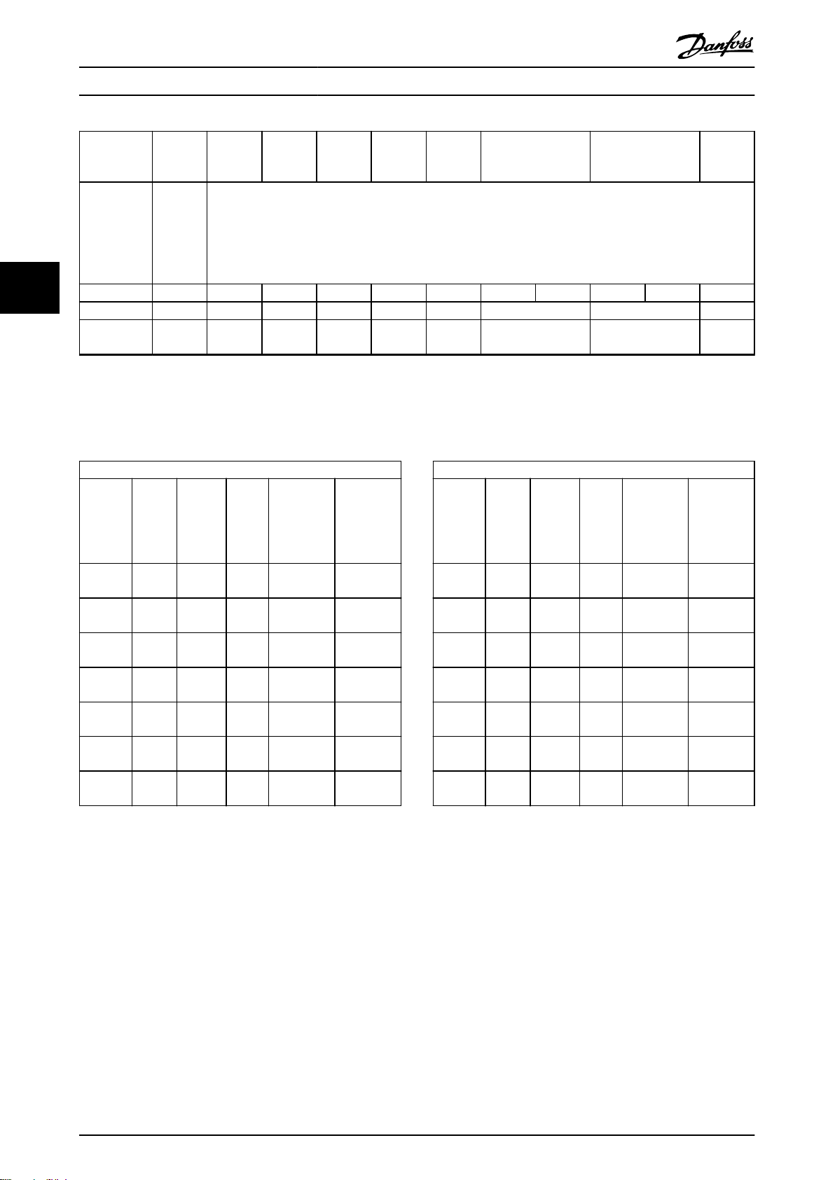
4.3.3 外部射频干扰滤波器
使用
表 4.11
(EN 55011 A1) 标准)或 20 米(65.6 英尺)(符合 EN/IEC 61800-3 C1(EN 55011 B) 标准)。
中列出的外部滤波器,可实现的最大屏蔽电缆长度为 50 米(164 英尺)(符合 EN/IEC 61800-3 C2
功率 [kW (hp)]
规格 380-480 V
0.37–2.2
44
(0.5–3.0)
3.0–7.5
(4.0–10)
11–15
(15–20)
18.5–22
(25–30)
表 4.11 RFI 滤波器 - 详细信息
类型 A B C D E F G H I J K L1
FN3258-7-45 190 40 70 160 180 20 4.5 1 10.6 M5 20 31
FN3258-16-45 250 45 70 220 235 25 4.5 1 10.6 M5 22.5 31
FN3258-30-47 270 50 85 240 255 30 5.4 1 10.6 M5 25 40
FN3258-42-47 310 50 85 280 295 30 5.4 1 10.6 M5 25 40
转矩
[Nm (in-lb)]
0.7–0.8
(6.2–7.1)
0.7–0.8
(6.2–7.1)
1.9–2.2
(16.8–19.5)
1.9–2.2
(16.8–19.5)
最大重量 [kg (lb)] 订购号
0.5
(1.1)
0.8
(1.8)
1.2
(2.6)
1.4
(3.1)
132B0244
132B0245
132B0246
132B0247
图 4.9 RFI 滤波器 - 尺寸
50 Danfoss A/S © 04/2018 全权所有。 MG18C841
Page 53

L1
L2
L3
3-phase
power
input
PE
PE
+10 V DC
0-10 V DC-
0-10 V DC-
50 (+10 V OUT)
54 (A IN)
53 (A IN)
55 (COM A IN/OUT)
0/4-20 mA
0/4-20 mA
42 0/4-20 mA A OUT / D OUT
45 0/4-20 mA A OUT / D OUT
18 (D IN)
19 (D IN)
27 (D IN/OUT)
29 (D IN/OUT)
12 (+24 V OUT)
24 V (NPN)
20 (COM D IN)
O V (PNP)
24 V (NPN)
O V (PNP)
24 V (NPN)
O V (PNP)
24 V (NPN)
O V (PNP)
Bus ter.
Bus ter.
RS485
Interface
RS485
(N RS485) 69
(P RS485) 68
(Com RS485 ) 61
(PNP)-Source
(NPN)-Sink
ON=Terminated
OFF=Unterminated
ON
1 2
240 V AC 3 A
Not present on all power sizes
Do not connect shield to 61
01
02
03
relay 1
relay 2
UDC+
UDC-
Motor
U
V
W
130BD467.12
06
05
04
240 V AC 3 A
安装 设计指南
5 安装
5.1 电气安装
5 5
图 5.1 基本接线示意图
注意
在下述设备上无 UDC- 和 UDC+:
•
•
•
•
所有接线都必须符合相关国家和地方关于电缆横截面积和环境温度的法规。必须使用铜导体。建议的温度规格为 75 °C
(167 °F)。
IP20, 380–480 V, 30–90 kW (40–125 HP)
IP20, 200–240 V, 15–45 kW (20–60 HP)
IP20, 525–600 V, 2.2–90 kW (3.0–125 hp)
IP54, 380–480 V, 22–90 kW (30–125 HP)
MG18C841 Danfoss A/S © 04/2018 全权所有。 51
Page 54

安装
VLT® HVAC Basic Drive FC 101
功率 [kW (hp)] 转矩 [Nm (in-lb)]
机箱规格 IP 等级 3x200–240 V 3x380–480 V 主电源 电动机 直流连接 控制端子 接地 继电器
H1 IP20
0.25–1.5
(0.33–2.0)
H2 IP20 2.2 (3.0)
H3 IP20 3.7 (5.0)
H4 IP20
5.5–7.5
(7.5–10)
H5 IP20 11 (15)
55
H6 IP20
H7 IP20
15–18.5
(20–25)
22–30 (30–
40)
0.37–1.5
(0.5–2.0)
2.2–4.0
(3.0–5.0)
5.5–7.5
(7.5–10)
11–15 (15–
20)
18.5–22
(25–30)
30–45 (40–
60)
0.8 (7.0) 0.8 (7.0) 0.8 (7.0) 0.5 (4.0) 0.8 (7.0) 0.5 (4.0)
0.8 (7.0) 0.8 (7.0) 0.8 (7.0) 0.5 (4.0) 0.8 (7.0) 0.5 (4.0)
0.8 (7.0) 0.8 (7.0) 0.8 (7.0) 0.5 (4.0) 0.8 (7.0) 0.5 (4.0)
1.2 (11) 1.2 (11) 1.2 (11) 0.5 (4.0) 0.8 (7.0) 0.5 (4.0)
1.2 (11) 1.2 (11) 1.2 (11) 0.5 (4.0) 0.8 (7.0) 0.5 (4.0)
4.5 (40) 4.5 (40) – 0.5 (4.0) 3 (27) 0.5 (4.0)
55 (70) 10 (89) 10 (89) – 0.5 (4.0) 3 (27) 0.5 (4.0)
H7 IP20 – 75 (100) 14 (124) 14 (124) – 0.5 (4.0) 3 (27) 0.5 (4.0)
H8 IP20
37–45 (50–
60)
90 (125)
24 (212)1)24 (212)
1)
– 0.5 (4.0) 3 (27) 0.5 (4.0)
表 5.1 H1–H8,3x200–240 V 和 3x380–480 V 机箱的紧固力矩
功率 [kW (hp)] 转矩 [Nm (in-lb)]
机箱规格 IP 等级 3x380–480 V 主电源 电动机 直流连接 控制端子 接地 继电器
I2 IP54
I3 IP54
I4 IP54
I6 IP54
I7 IP54
I8 IP54
0.75–4.0
(1.0–5.0)
5.5–7.5
(7.5–10)
11–18.5 (15–
25)
22–37 (30–
50)
45–55 (60–
70)
75–90 (100–
125)
0.8 (7.0) 0.8 (7.0) 0.8 (7.0) 0.5 (4.0) 0.8 (7.0) 0.5 (4.0)
0.8 (7.0) 0.8 (7.0) 0.8 (7.0) 0.5 (4.0) 0.8 (7.0) 0.5 (4.0)
1.4 (12) 0.8 (7.0) 0.8 (7.0) 0.5 (4.0) 0.8 (7.0) 0.5 (4.0)
4.5 (40) 4.5 (40) – 0.5 (4.0) 3 (27) 0.6 (5.0)
10 (89) 10 (89) – 0.5 (4.0) 3 (27) 0.6 (5.0)
14 (124)/24
(212)
2)
14 (124)/24
2)
(212)
– 0.5 (4.0) 3 (27) 0.6 (5.0)
表 5.2 I2–I8 机箱的紧固力矩
功率 [kW (hp)] 转矩 [Nm (in-lb)]
机箱规格 IP 等级 3x525–600 V 主电源 电动机 直流连接 控制端子 接地 继电器
H9 IP20
H10 IP20
H6 IP20
H7 IP20
H8 IP20
2.2–7.5
(3.0–10)
11–15 (15–
20)
18.5–30 (25–
40)
37–55 (50–
70)
75–90 (100–
125)
1.8 (16) 1.8 (16) 不建议 0.5 (4.0) 3 (27) 0.6 (5.0)
1.8 (16) 1.8 (16) 不建议 0.5 (4.0) 3 (27) 0.6 (5.0)
4.5 (40) 4.5 (40) – 0.5 (4.0) 3 (27) 0.5 (4.0)
10 (89) 10 (89) – 0.5 (4.0) 3 (27) 0.5 (4.0)
14 (124)/24
(212)
2)
14 (124)/24
2)
(212)
– 0.5 (4.0) 3 (27) 0.5 (4.0)
表 5.3 H6–H10,3x525–600 V 机箱的紧固力矩
1) 电缆尺寸 >95 mm
2) 电缆尺寸 ≤95 mm
2
2
52 Danfoss A/S © 04/2018 全权所有。 MG18C841
Page 55

130BB634.10
1
2
2
3
4
Motor
U
V
W
-DC
+DC
MAINS
1
95
99
L1 91 / L2 92 / L3 93
U 96 / V 97 / W 98
03 02 01
06 05 04
2
3
4
130BB762.10
安装 设计指南
5.1.1 主电源和电机接线
该变频器旨在控制各种标准的三相异步电机。有关电缆的
最大横截面积,请参阅
为符合 EMC 辐射规范,请使用屏蔽/铠装的电机
•
电缆,并将此电缆同时连接到去耦板和电机。
为了减小噪音水平和漏电电流,请使用尽可能短
•
的电机电缆。
有关安装去耦板的详细信息,请参阅 FC 101
•
耦板安装说明
另请参阅
•
中的“
有关如何将变频器连接到主电源和电机的详细信
•
息,请参阅
快速指南 中的“连接到主电源和电机”一章
H1–H5 机箱上的继电器和端子
章 8.4 常规技术数据
。
。
章 5.1.2 符合 EMC 规范的电气安装
符合 EMC 规范的安装
”。
VLT® HVAC Basic Drive FC 101
去
。
H6 机箱上的继电器和端子
5 5
1 主电源
2 电动机
3 接地
4 继电器
图 5.3 机箱规格 H6
IP20, 380–480 V, 30–45 kW (40–60 hp)
IP20, 200–240 V, 15–18.5 kW (20–25 hp)
IP20, 525–600 V, 22–30 kW (30–40 hp)
1 主电源
2 接地
3 电动机
4 继电器
图 5.2 机箱规格 H1–H5
IP20, 200–240 V, 0.25–11 kW (0.33–15 hp)
IP20, 380–480 V, 0.37–22 kW (0.5–30 hp)
MG18C841 Danfoss A/S © 04/2018 全权所有。 53
Page 56
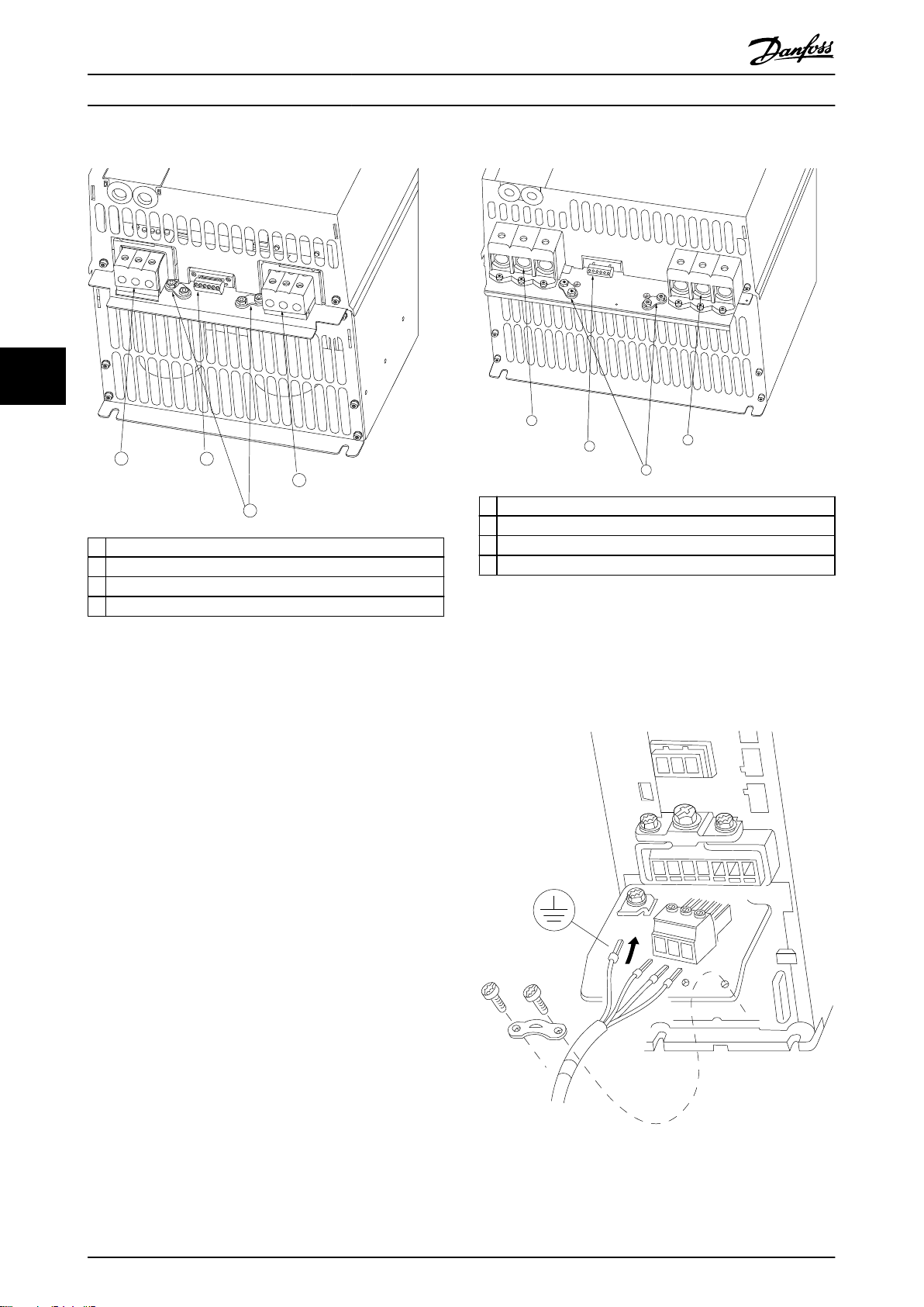
1
2
3
4
130BB763.10
130BB764.10
1
2
3
4
98
97
96
99
95
93
92
91
L1
L1
L1
U
V
w
MOTOR
MOTOR
U V W
99
130BT302.12
安装
VLT® HVAC Basic Drive FC 101
H7 机箱上的继电器和端子
H8 机箱上的继电器和端子
55
1 主电源
2 继电器
1 主电源
2 继电器
3 接地
4 电动机
图 5.4 机箱规格 H7
IP20, 380–480 V, 55–75 kW (70–100 hp)
IP20, 200–240 V, 22–30 kW (30–40 hp)
IP20, 525–600 V, 45–55 kW (60–70 hp)
3 接地
4 电动机
图 5.5 机箱规格 H8
IP20, 380–480 V, 90 kW (125 hp)
IP20, 200–240 V, 37–45 kW (50–60 hp)
IP20, 525–600 V, 75–90 kW (100–125 hp)
机箱规格 H9 的主电源和电动机接线
54 Danfoss A/S © 04/2018 全权所有。 MG18C841
图 5.6 机箱规格 H9 的电动机接线
IP20, 600 V, 2.2–7.5 kW (3.0–10 hp)
Page 57
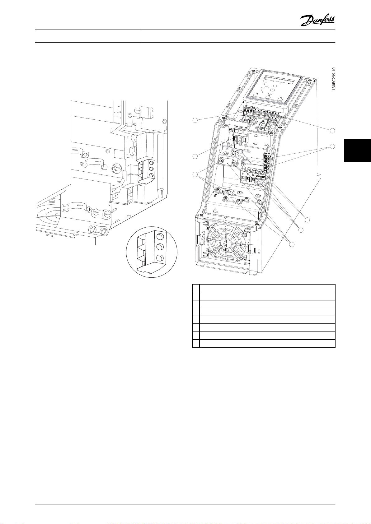
130BA725.10
130BC299.10
7
3
2
5
1
8
4
6
安装 设计指南
确保正确连接机箱规格 H9 的主电源电缆,有关详细信
息,请参阅
中的
“连接到主电源和电机”一章
电气安装
VLT® HVAC Basic Drive FC 101 快速指南
。使用
章 5.1.1 一般
中所述的紧固力矩。
H10 机箱上的继电器和端子
机箱规格 I2
5 5
图 5.7 机箱规格 H10
IP20, 600 V, 11–15 kW (15–20 hp)
1 RS485
2 主电源
3 接地
4 电缆夹
5 电动机
6 UDC
7 继电器
8 I/O
图 5.8 机箱规格 I2
IP54, 380–480 V, 0.75–4.0 kW (1.0–5.0 hp)
MG18C841 Danfoss A/S © 04/2018 全权所有。 55
Page 58

130BC201.10
130BD011.10
130BC203.10
安装
VLT® HVAC Basic Drive FC 101
机箱规格 I3
机箱规格 I4
55
1 RS485
2 主电源
3 接地
4 电缆夹
5 电动机
6 UDC
7 继电器
8 I/O
图 5.9 机箱规格 I3
IP54, 380–480 V, 5.5–7.5 kW (7.5–10 hp)
1 RS485
2 主电源
3 接地
4 电缆夹
5 电动机
6 UDC
7 继电器
8 I/O
图 5.10 机箱规格 I4
IP54, 380–480 V, 0.75–4.0 kW (1.0–5.0 hp)
图 5.11 IP54 机箱规格 I2、I3、I4
56 Danfoss A/S © 04/2018 全权所有。 MG18C841
Page 59

130BT326.10
130BT325.10
311
130BA215.10
RELAY 1
RELAY 2
9
9
6
03 02 01
90 05 04
91
L1
92
L2
93
L3
96
U
97
V
98
W
88
DC-
89
DC+
81
R-
8
R+
99
95
130BA248.10
安装 设计指南
机箱规格 I6
5 5
图 5.12 机箱规格 I6 的主电源接线
IP54, 380–480 V, 22–37 kW (30–50 hp)
图 5.13 机箱规格 I6 的电动机接线
IP54, 380–480 V, 22–37 kW (30–50 hp)
图 5.14 I6 机箱上的继电器
IP54, 380–480 V, 22–37 kW (30–50 hp)
机箱规格 I7、I8
图 5.15 机箱规格 I7、I8
IP54, 380–480 V, 45–55 kW (60–70 hp)
IP54, 380–480 V, 75–90 kW (100–125 hp)
MG18C841 Danfoss A/S © 04/2018 全权所有。 57
Page 60

安装
VLT® HVAC Basic Drive FC 101
5.1.2 符合 EMC 规范的电气安装
注意以下推荐以确保符合 EMC 规范的电气安装。
只能使用屏蔽/铠装电机电缆和屏蔽/铠装控制电缆。
•
将屏蔽层两端接地。
•
不要扭结屏蔽层端部(辫子状),否则会减弱高频下的屏蔽效果。应使用附随的电缆夹。
•
务必确保从安装板到安装螺钉乃至变频器金属机柜都保持良好的电接触性。
•
使用星形垫圈和导电安装板。
•
在系统机柜中勿使用非屏蔽/非铠装的电机电缆。
•
55
58 Danfoss A/S © 04/2018 全权所有。 MG18C841
Page 61

L1
L2
L3
PE
最小 16 mm
2
均衡电缆
控制电缆
所有电缆输入位于面板一侧
接地导轨
电缆绝缘剥皮
输出接头
电动机电缆
电动机,3 相和保护性接地
PLC 等
面板
主电源
最小 200mm
控制电缆
与主电源线之间
主电源线与
电动机电缆之间
PLC
增强保护性接地
130BB761.10
安装 设计指南
5 5
图 5.16 符合 EMC 规范的电气安装
注意
对于北美市场,请使用金属线管而不是屏蔽电缆。
MG18C841 Danfoss A/S © 04/2018 全权所有。 59
Page 62

130BF892.10
12 20 55
181927 29 42 54
45 50 53
DIGI IN
61 68 69
N
P
COMM. GND
+24 V
GND
GND
10 V OUT
10 V/20 mA IN
0/4-20 mA A OUT/DIG OUT
BUS TER.
OFF ON
DIGI IN
DIGI IN
DIGI IN
0/4-20 mA A OUT/DIG OUT
10 V/20 mA IN
安装
5.1.3 控制端子
VLT® HVAC Basic Drive FC 101
请参考
图 5.17
VLT® HVAC Basic Drive FC 101 快速指南
并确保已正确拆除端子盖。
显示了变频器的所有控制端子。通过施加启动信号(端子 18),端子 12 与 27 之间的连接以及模拟参考值
(端子 53 或 54 和 55)可以使变频器运行。
端子 18、19 和 27 的数字输入模式在
数 5-03 数字输入 29 模式
中设置(默认值为 PNP)。
参数 5-00 数字输入模式
中设置(默认值为 PNP)。数字输入 29 模式在
参
55
图 5.17 控制端子
60 Danfoss A/S © 04/2018 全权所有。 MG18C841
Page 63

B
a
c
k
Com.
1-20 Motor Power
[5] 0.37kW - 0.5HP
Setup 1
AB1
12
131415
11
11
109876
5
432
C
D
Sta
tus
M
ain
M
enu
Q
uick
M
enu
Hand
On
OK
M
enu
Off
Reset
Auto
On
Alarm
Warn.
On
11
编程 设计指南
6 编程
6.1 简介
安装 MCT 10 设置软件 后,还可以通过 PC 的 RS-485
通讯端口从 LCP 对变频器进行设置。有关软件的详细信
息,请参阅
章 1.5 其他资源
。
6.2 本地控制面板 (LCP)
LCP 分为四个功能区。
A. 显示屏
B. 菜单键
C. 导航键和指示灯
D. 操作键和指示灯
1 参数编号和名称。
2 参数值。
菜单编号显示有效菜单和编辑菜单。如果有效菜单和编辑
菜单是同一个菜单,则仅显示该菜单编号(出厂设置)。
3
如果有效菜单和编辑菜单不同,则两个编号都显示(菜单
12)。编号在闪烁的菜单为编辑菜单。
屏幕左下侧显示了电机方向,用一个顺时针或逆时针方向
4
的小箭头表示。
三角形表示 LCP 是位于状态菜单、快捷菜单还是主菜单
5
下。
表 6.1
图 6.1
的图例,部分 I
B. 菜单键
按 [Menu](菜单)键可在状态菜单、快捷菜单和主菜单
之间切换。
C. 导航键和指示灯
6 通讯 LED: 在总线通讯过程中闪烁。
7 绿色 LED/启动: 控制部分工作正常。
8 黄色 LED/警告: 表明发生警告。
9 闪烁的红色 LED/报警: 表明发生报警。
10 [Back](后退): 返回导航结构的上一步或上一层。
[▲] [▼] [►]: 用于在参数组间、参数间和参数内进行导
11
航。也用于设置本地参考值。
12 [OK](确定): 用于选择参数和接受对参数设置的更改。
6
6
图 6.1 本地控制面板 (LCP)
A. 显示屏
LCD 显示器显示 2 行字母数字信息。所有数据显示在
LCP 上。
图 6.1
介绍可从显示屏读取的信息。
表 6.2
图 6.1
的图例,部分 II
D. 操作键和指示灯
[Hand On](手动启动): 启动电机,并允许通过 LCP
控制变频器。
注意
[2] 惯性停车反逻辑是参数 5-12 端子 27 数字输
13
入
的默认选项。如果端子 27 上无 24 V 电压,
使用 [Hand On](手动启动)将无法启动电机。将
端子 12 连接到端子 27。
[Off/Reset](停止/复位): 用于停止电机(关)。在报
14
警模式下,报警被复位。
[Auto On](自动启动): 可以通过控制端子或串行通讯
15
来控制变频器。
表 6.3
图 6.1
的图例,部分 III
MG18C841 Danfoss A/S © 04/2018 全权所有。 61
Page 64
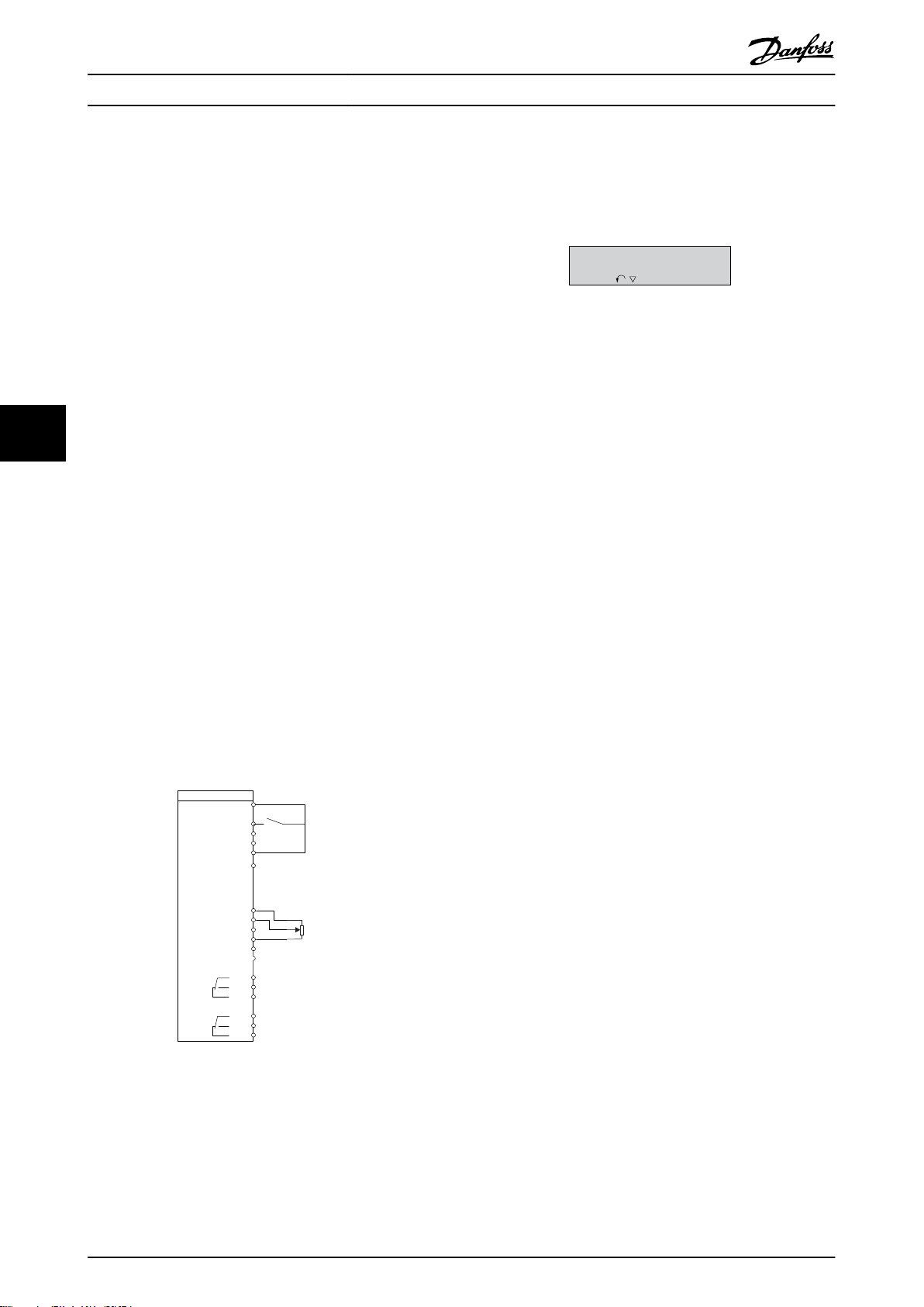
FC
+24V
数字输入
数字输入
数字输入
数字输入
数字通讯输入
模拟输出/数字输出
模拟输出/数字输出
18
19
27
29
42
55
50
53
54
20
12
01
02
03
04
05
06
R2
R1
+
-
0-10V
参考值
启动
+10V
模拟输入
模拟输入
通讯
130BB676.10
45
130BB629.10
Press OK to start Wizard
Push Back to skip it
Setup 1
编程
VLT® HVAC Basic Drive FC 101
6
6.3 菜单
6.3.1 状态菜单
状态
菜单中包括以下选项:
电机频率 [Hz],
•
电机电流 [A],
•
电机速度参考值,以百分比表示 [%],
•
数 16-02 参考值 [%]
反馈,
•
•
参数 16-52 反馈 [单位]
电机功率
数 16-11 功率 [hp]
数 0-03 区域性设置
参数 16-13 频率
参数 16-14 电动机电流
。
参数 16-10 功率 [kW]
(hp)。如果
设置为
[1] 北美
。
。
(kW),
参
。
参
参
,电机
功率显示单位将是 hp,而不是 kW。
自定义读数,
•
电动机速度 [RPM],
•
参数 16-09 自定义读数
参数 16-17 速度 [RPM]
。
。
6.3.2 快捷菜单
借助快捷菜单可设置最常用的功能。快捷菜单包括以下内
容:
开环应用向导。有关详细信息,请参阅
•
图 6.4
。
用于闭环应用的向导。有关详细信息,请参阅
•
图 6.5
。
电机设置。有关详细信息,请参阅
•
已完成的更改。
•
内置的向导菜单引导安装人员以一种清晰的结构化方式设
置变频器,以便进行开环、闭环应用及快速电机设置。
表 6.6
。
除非更改了任何参数,否则系统启动之后都会显示出该向
导。该向导始终可以通过快捷菜单来访问。要启动该向
导,请按 [OK](确定)。按 [Back](返回)可返回到状
态视图。
图 6.3 启动/退出向导
62 Danfoss A/S © 04/2018 全权所有。 MG18C841
图 6.2 变频器接线
Page 65

Power kW/50 Hz
OK
Motor Power
Motor Voltage
Motor Frequency
Motor Current
Motor nominal speed
if
Select Regional Settings
... the Wizard starts
200-240V/50Hz/Delta
Grid Type
Asynchronous motor
Asynchronous
Motor Type
Motor current
Motor nominal speed
Motor Cont. Rated Torque
Stator resistance
Motor poles
Back EMF at 1000 rpm
Motor type = IPM
Motor type = SPM
d-axis Inductance Sat. (LdSat)
[0]
[0]
3.8
A
3000
RPM
5.4
Nm
0.65
Ohms
8
Start Mode
Rotor Detection
[0]
Position Detection Gain
%
Off
100
Locked Rotor Detection
[0]
s
Locked Rotor Detection Time[s]
0.10
57
V
5
mH
q-axis Inductance (Lq)
5
mH
1.10
kW
400
V
50
Hz
Max Output Frequency
65
Hz
Motor Cable Length
50
m
4.66
A
1420
RPM
[0]
PM motor
Set Motor Speed low Limit
Hz
Set Motor Speed high Limit
Hz
Set Ramp 1 ramp-up time
s
Set Ramp 1 ramp-down Time
s
Active Flying start?
Disable
Set T53 low Voltage
V
Set T53 high Voltage
V
Set T53 Low Current
A
Set T53 High Current
A
Voltage
AMA Failed
AMA Failed
Automatic Motor Adaption
Auto Motor Adapt OK
Press OK
Select Function of Relay 2
No function
Off
Select Function of Relay 1
[0] No function
Set Max Reference
Hz
Hz
Set Min Reference
AMA running
-----
Do AMA
(Do not AMA)
AMA OK
[0]
[0]
[0]
Select T53 Mode
Current
Current
Motor type = Asynchronous
Motor type = PM motor
0000
0050
0010
0010
[0]
[0]
04.66
13.30
0050
0220
0000
0050
B
a
c
k
Status Screen
The Wizard can always be
reentered via the Quick Menu
At power-up, select the
preferred language.
The next screen is
the Wizard screen.
Wizard Screen
if
OK
Power-up Screen
Status
Main
Menu
Quick
Menu
Hand
On
OK
Menu
Reset
Off
Auto
On
Alarm
Warn.
On
Select language
[1] English
Setup 1
B
a
c
k
Com.
Status
Main
Menu
Quick
Menu
Hand
On
OK
Menu
Reset
Off
Auto
On
Alarm
Warn.
On
Press OK to start Wizard
Press Back to skip it
Setup 1
B
a
c
k
Com.
Status
Main
Menu
Quick
Menu
Hand
On
OK
Menu
Reset
Off
Auto
On
Alarm
Warn.
On
0.0 Hz
0.0 kW
Setup 1
B
a
c
k
Com.
130BC244.16
q-axis Inductance Sat. (LqSat)
5
mH
Current at Min Inductance for d-axis
100
%
Current at Min Inductance for q-axis
100
%
d-axis Inductance (Lq)
5
mH
... the Wizard starts
编程 设计指南
6
6
图 6.4 开环应用设置向导
MG18C841 Danfoss A/S © 04/2018 全权所有。 63
Page 66
编程
VLT® HVAC Basic Drive FC 101
开环应用设置向导
参数 选项 默认 使用
参数 0-03 区域性设置 [0] 国际
[1] 北美
[0] 国际
–
6
参数 0-06 电网类型 [0] 200–240 V/50
Hz/IT-grid
[1] 200–240 V/50 Hz/
Delta
[2] 200–240 V/50 Hz
[10] 380–440 V/50
Hz/IT-grid
[11] 380–440 V/50
Hz/Delta
[12] 380–440 V/50 Hz
[20] 440–480 V/50
Hz/IT-grid
[21] 440–480 V/50
Hz/Delta
[22] 440–480 V/50 Hz
[30] 525–600 V/50
Hz/IT-grid
[31] 525–600 V/50
Hz/Delta
[32] 525–600 V/50 Hz
[100] 200–240 V/60
Hz/IT-grid
[101] 200–240 V/60
Hz/Delta
[102] 200–240 V/60
Hz
[110] 380–440 V/60
Hz/IT-grid
[111] 380–440 V/60
Hz/Delta
[112] 380–440 V/60
Hz
[120] 440–480 V/60
Hz/IT-grid
[121] 440–480 V/60
Hz/Delta
[122] 440–480 V/60
Hz
[130] 525–600 V/60
Hz/IT-grid
[131] 525–600 V/60
Hz/Delta
[132] 525–600 V/60
Hz
与规格有关 选择在断电后重新将变频器连接到主电源时用于重新启动
的运行模式。
64 Danfoss A/S © 04/2018 全权所有。 MG18C841
Page 67
编程 设计指南
参数 选项 默认 使用
参数 1-10 电机结构 *[0] 异步
[1] PM,非突出 SPM
[3] PM,突出 IPM
[0] 异步
设置参数值后可能会更改以下参数:
•
•
•
•
•
•
•
•
•
•
•
•
•
•
•
•
•
•
•
•
•
•
•
•
•
•
•
•
•
•
•
•
•
•
•
•
•
•
•
•
•
参数 1-01 电动控制原理
参数 1-03 转矩特性
参数 1-08 电机控制带宽
参数 1-14 衰减增益
参数 1-15 低速滤波时间常量
参数 1-16 高速滤波时间常量
参数 1-17 电压滤波时间常量
参数 1-20 电机功率
参数 1-22 电机电压
参数 1-23 电机频率
参数 1-24 电动机电流
参数 1-25 电机额定转速
参数 1-26 电机连续 额定转矩
参数 1-30 定子阻抗 (Rs)
参数 1-33 定子漏抗 (X1)
参数 1-35 主电抗 (Xh)
参数 1-37 d 轴电感 (Ld)
参数 1-38 q 轴电感 (Lq)
参数 1-39 电机极数
参数 1-40 1000 RPM 时的反电动势
参数 1-44 d 轴电感 Sat. (LdSat)
参数 1-45 q 轴电感 Sat. (LqSat)
参数 1-46 位置检测增益
参数 1-48 d 轴最小电感电流
参数 1-49 q 轴最小电感电流
参数 1-66 低速最小电流
参数 1-70 启动模式
参数 1-72 启动功能
参数 1-73 飞车启动
参数 1-80 停止功能
参数 1-82 停止功能最低速 [Hz]
参数 1-90 电机热保护
参数 2-00 直流夹持/电机预热电流
参数 2-01 直流制动电流
参数 2-02 直流制动时间
参数 2-04 直流制动切入速度
参数 2-10 制动功能
参数 4-14 电机速度上限 [Hz]
参数 4-19 最大输出频率
参数 4-58 电机缺相功能
参数 14-65 速度降容空载时间补偿
.
.
.
.
.
.
.
.
.
.
.
.
.
.
.
.
.
.
.
.
.
.
.
.
.
.
.
.
.
.
.
.
.
6
6
.
.
.
.
.
MG18C841 Danfoss A/S © 04/2018 全权所有。 65
Page 68
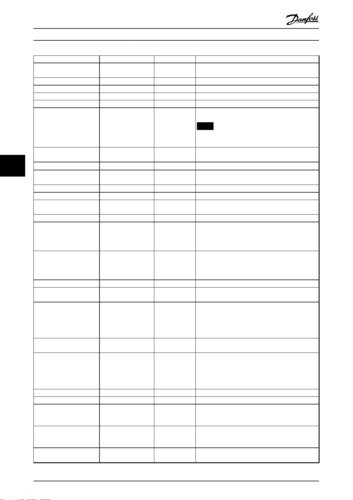
编程
参数 选项 默认 使用
参数 1-20 电机功率
参数 1-22 电机电压
参数 1-23 电机频率
参数 1-24 电动机电流
参数 1-25 电机额定转速
参数 1-26 电机连续 额定转
0.12–110 kW/0.16–
150 hp
50–1000 V 与规格有关 根据铭牌数据输入电机电压。
20–400 Hz 与规格有关 根据铭牌数据输入电机频率。
0.01–10000.00 A 与规格有关 根据铭牌数据输入电机电流。
50–9999 RPM 与规格有关 根据铭牌数据输入电机额定转速。
0.1–1000.0 Nm 与规格有关 当
矩
VLT® HVAC Basic Drive FC 101
与规格有关 根据铭牌数据输入电机功率。
时,可使用该参数。
注意
更改该参数会影响其他参数的设置。
参数 1-10 电机结构
设为启用永磁电机模式的选项
6
参数 1-29 电机自动整定
(AMA)
参数 1-30 定子阻抗 (Rs)
参数 1-37 d 轴电感 (Ld)
参数 1-38 q 轴电感 (Lq)
参数 1-39 电机极数
参数 1-40 1000 RPM 时的反
请参阅
参数 1-29 电机
自动整定 (AMA)
0.000–99.990 Ω 与规格有关 设置定子阻抗值。
0.000–1000.000 mH 与规格有关 输入 d 轴电感值。
0.000–1000.000 mH 与规格有关 输入 q 轴电感值。
2–100 4 输入电机极数。
10–9000 V 与规格有关 1000 RPM 时的线路间 RMS 反电动势。
电动势
参数 1-42 电机电缆长度
参数 1-44 d 轴电感 Sat.
0–100 m 50 m 输入电机电缆长度。
0.000–1000.000 mH 与规格有关 此参数与 Ld 的饱和电感相对应。理想情况是,此参数与
(LdSat)
参数 1-45 q 轴电感 Sat.
0.000–1000.000 mH 与规格有关 此参数与 Lq 的饱和电感相对应。理想情况是,此参数与
(LqSat)
参数 1-46 位置检测增益
参数 1-48 d 轴最小电感电
20–200% 100% 在启动时的位置检测期间,调整测试脉冲的高度。
20–200% 100% 输入电感饱和点。
流
参数 1-49 q 轴最小电感电
20–200% 100% 该参数指定 d- 和 q- 电感值的饱和曲线。由于
流
参数 1-70 启动模式 [0] 转子检测
[1] 停车
参数 1-73 飞车启动 [0] 禁用
[1] 启用
参数 3-02 最小参考值
参数 3-03 最大参考值
参数 3-41 斜坡 1 加速时间
参数 3-42 斜坡 1 减速时间
参数 4-12 电机速度下限
-4999.000–4999.000 0 最小参考值是通过汇总所有参考值获得的最小值。
-4999.000–4999.000 50 最大参考值是通过汇总所有参考值而获得的最大值。
0.05–3600.00 s 与规格有关 如果选择异步电机,加速时间从 0 到额定
0.05–3600.00 s 与规格有关 对于异步电机,减速时间是从额定
0.0–400.0 Hz 0 Hz 输入速度下限。
[Hz]
关 通过执行 AMA 来优化电动机性能。
。
该值可从永磁电机数据表中找到。
参数 1-37 d 轴电感 (Ld)
电机供应商提供了电感曲线,则输入标称电流的 200% 作
为电感值。
参数 1-38 q 轴电感 (Lq)
电机供应商提供了电感曲线,则输入标称电流的 200% 作
为电感值。
具有相同的值。但是,如果
具有相同的值。但是,如果
参
数 1-37 d 轴电感 (Ld)、参数 1-38 q 轴电感 (Lq)
、
参数 1-44 d 轴电感 Sat. (LdSat)和参数 1-45 q 轴
[0] 转子检测
[0] 禁用
电感 Sat. (LqSat)
性近似。
选择 PM 电机启动模式。
选择
[1] 启用
于旋转中的电机。如果不需要该功能,应选择
用
。当此参数设置为
迟
和
参数 1-72 启动功能
仅在 VVC+ 模式下有效。
,该参数 20% 至 100% 的电感值线
以便变频器能够捕获由于主电源断开而处
[0] 禁
[1] 启用 时,参数 1-71 启动延
无效。
参数 1-73 飞车启动
参
数 1-23 电机频率
到
参数 1-25 电机额定转速
。如果选择永磁电机,加速时间是从 0
。
参数 1-23 电机频率
到 0。对于永磁电机,减速时间为从
定转速
到 0。
参数 1-25 电机额
66 Danfoss A/S © 04/2018 全权所有。 MG18C841
Page 69

编程 设计指南
参数 选项 默认 使用
参数 4-14 电机速度上限
[Hz]
参数 4-19 最大输出频率
参数 5-40 继电器功能
参数 5-40 继电器功能
参数 6-10 端子 53 低电压
参数 6-11 端子 53 高电压
参数 6-12 端子 53 低电流
参数 6-13 端子 53 高电流
参数 6-19 Terminal 53
mode
参数 30-22 转子堵转保护 [0] 关闭
参数 30-23 转子堵转检测时
间 [s]
0.0–400.0 Hz 100 Hz 输入速度上限。
0.0–400.0 Hz 100 Hz 输入最大输出频率值。如果
于
度上限 [Hz]
率
请参阅
参数 5-40 继电
器功能
。
请参阅
参数 5-40 继电
器功能
。
0.00–10.00 V 0.07 V 输入与低参考值对应的电压。
0.00–10.00 V 10 V 输入与高参考值对应的电压。
0.00–20.00 mA 4 mA 输入与低参考值对应的电流。
0.00–20.00 mA 20 mA 输入与高参考值对应的电流。
[0] 电流
[1] 电压
[1] 打开
0.05–1 s 0.10 s
[9] 报警
[5] 变频器在运行
[1] 电压
[0] 关
选择用于控制输出继电器 1 的功能。
选择用于控制输出继电器 2 的功能。
选择端子 53 是用于电流还是用于电压输入。
–
–
参数 4-19 最大输出频率
参数 4-14 电机速度上限 [Hz],则参数 4-14 电机速
自动被设置为等于
。
参数 4-19 最大输出频
小
6
6
表 6.4 开环应用设置向导
MG18C841 Danfoss A/S © 04/2018 全权所有。 67
Page 70
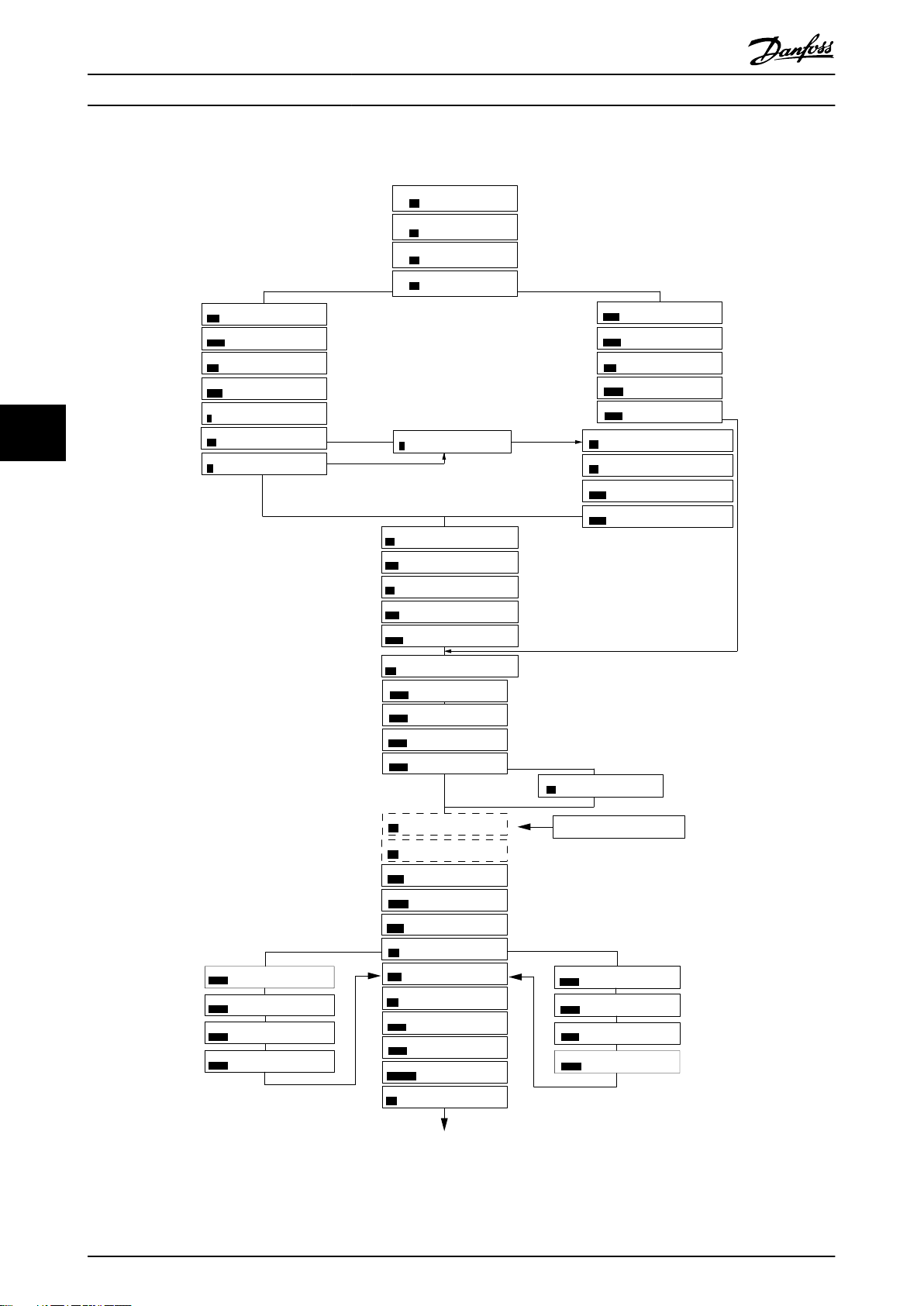
6-29 Terminal 54 Mode
[1]
Voltage
6-25 T54 high Feedback
0050
Hz
20-94 PI integral time
0020.00
s
Current
Voltage
This dialog is forced to be set to
[1] Analog input 54
20-00 Feedback 1 source
[1]
Analog input 54
3-10 Preset reference [0]
0.00
3-03 Max Reference
50.00
3-02 Min Reference
0.00
Asynchronous motor
1-73 Flying Start
[0]
No
1-22 Motor Voltage
400
V
1-24 Motor Current
04.66
A
1-25 Motor nominal speed
1420
RPM
3-41 Ramp 1 ramp-up time
0010
s
3-42 Ramp1 ramp-down time
0010
s
0-06 Grid Type
4-12 Motor speed low limit
0016
Hz
4-13 Motor speed high limit
0050
Hz
130BC402.14
1-20 Motor Power
1.10
kW
1-23 Motor Frequency
50
Hz
6-22 T54 Low Current
A
6-24 T54 low Feedback
0016
Hz
6-23 T54 high Current
13.30
A
6-25 T54 high Feedback
0050
0.01
s
20-81 PI Normal/Inverse Control
[0]
Normal
20-83 PI Normal/Inverse Control
0050
Hz
20-93 PI Proportional Gain
00.50
1-29 Automatic Motor Adaption
[0]
Off
6-20 T54 low Voltage
0050
V
6-24 T54 low Feedback
0016
Hz
6-21 T54 high Voltage
0220
V
6-26
T54 Filter time const.
1-00 Configuration Mode
[3]
Closed Loop
0-03 Regional Settings
[0]
Power kW/50 Hz
3-16 Reference Source 2
[0]
No Operation
1-10 Motor Type
[0]
Asynchronous
[0]
200-240V/50Hz/Delta
1-30 Stator Resistance
0.65
Ohms
1-25 Motor Nominal Speed
3000
RPM
1-24 Motor Current
3.8
A
1-26 Motor Cont. Rated Torque
5.4
Nm
1-38 q-axis inductance(Lq)
5
mH
4-19 Max Ouput Frequency
0065
Hz
1-40 Back EMF at 1000 RPM
57
V
PM motor
1-39 Motor Poles
8
%
04.66
Hz
Motor type = Asynchronous
Motor type = PM motor
Motor type = IPM
Motor type = SPM
1-44 d-axis Inductance Sat. (LdSat)
(1-70) Start Mode
Rotor Detection
[0]
1-46 Position Detection Gain
%
Off
100
30-22 Locked Rotor Detection
[0]
s
30-23 Locked Rotor Detection Time[s]
0.10
5
mH
1-42 Motor Cable Length
50
m
(1-45) q-axis Inductance Sat. (LqSat)
5
mH
(1-48) Current at Min Inductance for d-axis
100
%
1-49 Current at Min Inductance for q-axis
100
%
1-37 d-axis inductance(Lq)
5
mH
... the Wizard starts
... the Wizard starts
编程
闭环应用设置向导
6
VLT® HVAC Basic Drive FC 101
68 Danfoss A/S © 04/2018 全权所有。 MG18C841
图 6.5 闭环应用设置向导
Page 71

编程 设计指南
参数 范围 默认 使用
参数 0-03 区域性设置 [0] 国际
[1] 北美
参数 0-06 电网类型
参数 1-00 配置模式 [0] 开环
[0]–[132] 请参阅
表 6.4
。
[3] 闭环
[0] 国际
所选规格 选择在断电后重新将变频器连接到主电源时用于重新启动
[0] 开环
–
的运行模式。
选择
[3] 闭环
。
6
6
MG18C841 Danfoss A/S © 04/2018 全权所有。 69
Page 72

6
编程
参数 范围 默认 使用
参数 1-10 电机结构 *[0] 异步
[1] PM,非突出 SPM
[3] PM,突出 IPM
VLT® HVAC Basic Drive FC 101
[0] 异步
设置参数值后可能会更改以下参数:
•
•
•
•
•
•
•
•
•
•
•
•
•
•
•
•
•
•
•
•
•
•
•
•
•
•
•
•
•
•
•
•
•
•
•
•
•
•
•
•
•
参数 1-01 电动控制原理
参数 1-03 转矩特性
参数 1-08 电机控制带宽
参数 1-14 衰减增益
参数 1-15 低速滤波时间常量
参数 1-16 高速滤波时间常量
参数 1-17 电压滤波时间常量
参数 1-20 电机功率
参数 1-22 电机电压
参数 1-23 电机频率
参数 1-24 电动机电流
参数 1-25 电机额定转速
参数 1-26 电机连续 额定转矩
参数 1-30 定子阻抗 (Rs)
参数 1-33 定子漏抗 (X1)
参数 1-35 主电抗 (Xh)
参数 1-37 d 轴电感 (Ld)
参数 1-38 q 轴电感 (Lq)
参数 1-39 电机极数
参数 1-40 1000 RPM 时的反电动势
参数 1-44 d 轴电感 Sat. (LdSat)
参数 1-45 q 轴电感 Sat. (LqSat)
参数 1-46 位置检测增益
参数 1-48 d 轴最小电感电流
参数 1-49 q 轴最小电感电流
参数 1-66 低速最小电流
参数 1-70 启动模式
参数 1-72 启动功能
参数 1-73 飞车启动
参数 1-80 停止功能
参数 1-82 停止功能最低速 [Hz]
参数 1-90 电机热保护
参数 2-00 直流夹持/电机预热电流
参数 2-01 直流制动电流
参数 2-02 直流制动时间
参数 2-04 直流制动切入速度
参数 2-10 制动功能
参数 4-14 电机速度上限 [Hz]
参数 4-19 最大输出频率
参数 4-58 电机缺相功能
参数 14-65 速度降容空载时间补偿
.
.
.
.
.
.
.
.
.
.
.
.
.
.
.
.
.
.
.
.
.
.
.
.
.
.
.
.
.
.
.
.
.
.
.
.
.
.
70 Danfoss A/S © 04/2018 全权所有。 MG18C841
Page 73

编程 设计指南
参数 范围 默认 使用
参数 1-20 电机功率
参数 1-22 电机电压
参数 1-23 电机频率
参数 1-24 电动机电流
参数 1-25 电机额定转速
参数 1-26 电机连续 额定转
矩
0.09–110 kW 与规格有关 根据铭牌数据输入电机功率。
50–1000 V 与规格有关 根据铭牌数据输入电机电压。
20–400 Hz 与规格有关 根据铭牌数据输入电机频率。
0–10000 A 与规格有关 根据铭牌数据输入电机电流。
50–9999 RPM 与规格有关 根据铭牌数据输入电机额定转速。
0.1–1000.0 Nm 与规格有关 当
时,可使用该参数。
注意
更改该参数会影响其他参数的设置。
参数 1-10 电机结构
设为启用永磁电机模式的选项
参数 1-29 电机自动整定
(AMA)
参数 1-30 定子阻抗 (Rs)
参数 1-37 d 轴电感 (Ld)
参数 1-38 q 轴电感 (Lq)
参数 1-39 电机极数
参数 1-40 1000 RPM 时的反
电动势
参数 1-42 电机电缆长度
参数 1-44 d 轴电感 Sat.
(LdSat)
参数 1-45 q 轴电感 Sat.
(LqSat)
参数 1-46 位置检测增益
参数 1-48 d 轴最小电感电
流
参数 1-49 q 轴最小电感电
流
参数 1-70 启动模式 [0] 转子检测
参数 1-73 飞车启动 [0] 禁用
参数 3-02 最小参考值
参数 3-03 最大参考值
参数 3-10 预置参考值
参数 3-41 斜坡 1 加速时间
参数 3-42 斜坡 1 减速时间
参数 4-12 电机速度下限
[Hz]
参数 4-14 电机速度上限
[Hz]
关 通过执行 AMA 来优化电动机性能。
0–99.990 Ω 与规格有关 设置定子阻抗值。
0.000–1000.000 mH 与规格有关 输入 d 轴电感值。
0.000–1000.000 mH 与规格有关 输入 q 轴电感值。
2–100 4 输入电机极数。
10–9000 V 与规格有关 1000 RPM 时的线路间 RMS 反电动势。
0–100 m 50 m 输入电机电缆长度。
0.000–1000.000 mH 与规格有关 此参数与 Ld 的饱和电感相对应。理想情况是,此参数与
0.000–1000.000 mH 与规格有关 此参数与 Lq 的饱和电感相对应。理想情况是,此参数与
20–200% 100% 在启动时的位置检测期间,调整测试脉冲的高度。
20–200% 100% 输入电感饱和点。
20–200% 100% 该参数指定 d- 和 q- 电感值的饱和曲线。由于
[1] 停车
[1] 启用
-4999.000–4999.000 0 最小参考值是通过汇总所有参考值获得的最小值。
-4999.000–4999.000 50 最大参考值是通过汇总所有参考值而获得的最大值。
-100–100% 0 输入给定值。
0.05–3600.0 s 与规格有关 从 0 到额定
0.05–3600.0 s 与规格有关 从额定
0.0–400.0 Hz 0.0 Hz 输入速度下限。
0.0–400.0 Hz 100 Hz 输入速度上限。
[0] 转子检测
[0] 禁用
该值可从永磁电机数据表中找到。
参数 1-37 d 轴电感 (Ld)
电机供应商提供了电感曲线,则输入标称电流的 200% 作
为电感值。
参数 1-38 q 轴电感 (Lq)
电机供应商提供了电感曲线,则输入标称电流的 200% 作
为电感值。
数 1-37 d 轴电感 (Ld)、参数 1-38 q 轴电感 (Lq)
参数 1-44 d 轴电感 Sat. (LdSat)和参数 1-45 q 轴
电感 Sat. (LqSat)
性近似。
选择 PM 电机启动模式。
如果希望变频器能够捕获旋转的电机(如风扇应用),请
选择
[1] 启用
步电机)。从 0 到
间(对于永磁电机)。
步电机)。从
间(对于永磁电机)。
。当选择 PM 时,将启用此参数。
参数 1-23 电机频率
参数 1-23 电机频率
参数 1-25 电机额定转速
具有相同的值。但是,如果
具有相同的值。但是,如果
参
,该参数 20% 至 100% 的电感值线
的加速时间(对于异
参数 1-25 电机额定转速
到 0 的减速时间(对于异
的加速时
到 0 的减速时
、
6
6
MG18C841 Danfoss A/S © 04/2018 全权所有。 71
Page 74

6
编程
参数 范围 默认 使用
参数 4-19 最大输出频率
0.0–400.0 Hz 100 Hz 输入最大输出频率值。如果
VLT® HVAC Basic Drive FC 101
于
度上限 [Hz]
率
参数 6-20 端子 54 低电压
参数 6-21 端子 54 高电压
参数 6-22 端子 54 低电流
参数 6-23 端子 54 高电流
参数 6-24 端子 54 低参考/
反馈 值
参数 6-25 端子 54 高参考/
反馈 值
参数 6-26 端子 54 滤波器
0.00–10.00 V 0.07 V 输入与低参考值对应的电压。
0.00–10.00 V 10.00 V 输入与高参考值对应的电压。
0.00–20.00 mA 4.00 mA 输入与低参考值对应的电流。
0.00–20.00 mA 20.00 mA 输入与高参考值对应的电流。
-4999–4999 0 输入与在
54 低电流
-4999–4999 50 输入与在
54 高电流
0.00–10.00 s 0.01 输入滤波器时间常数。
时间
参数 6-29 端子 54 的模式 [0] 电流
[1] 电压
选择端子 54 是用于电流输入还是电压输入。
[1] 电压
参数 20-81 PI 正常/反向控制[0] 正常
[1] 反向
参数 20-83 PID 启动速度
0–200 Hz 0 Hz 输入作为 PI 控制启动信号的电机速度
[0] 正常
如果选择
过程误差为正时增加输出速度。选择
出速度。
[Hz]
参数 20-93 PI 比例增益
参数 20-94 PI Integral
Time
参数 30-22 转子堵转保护 [0] 关闭
参数 30-23 转子堵转检测时
间 [s]
0.00–10.00 0.01 输入过程控制器比例增益。在较高放大倍数下可以获得更
快速的控制。但是,如果放大倍数过高,控制过程可能变
得不稳定。
0.1–999.0 s 999.0 s 输入过程控制器积分时间。较短的积分时间可以实现快速
控制,但如果积分时间过短,过程可能会变得不稳定。积
分时间过长会使积分操作停止。
[0] 关
[1] 打开
0.05–1.00 s 0.10 s
–
–
参数 4-19 最大输出频率
小
参数 4-14 电机速度上限 [Hz],则参数 4-14 电机速
自动被设置为等于
。
参数 4-19 最大输出频
参数 6-20 端子 54 低电压/参数 6-22 端子
中设置的电压或电流对应的反馈值。
参数 6-21 端子 54 高电压/参数 6-23 端子
中设置的电压或电流对应的反馈值。
[0] 正常
,则会对过程控制进行设置,让它在
[1] 反向
将减小输
表 6.5 闭环应用设置向导
电机设置
电机设置向导指导用户完成设置所需的电机参数。
参数 范围 默认 使用
参数 0-03 区域性设置 [0] 国际
0 –
[1] 北美
参数 0-06 电网类型
[0]–[132] 请参阅
表 6.4
。
与规格有关 选择在断电后重新将变频器连接到主电源时用于重新启动
的运行模式。
72 Danfoss A/S © 04/2018 全权所有。 MG18C841
Page 75

编程 设计指南
参数 范围 默认 使用
参数 1-10 电机结构 *[0] 异步
[1] PM,非突出 SPM
[3] PM,突出 IPM
[0] 异步
设置参数值后可能会更改以下参数:
•
•
•
•
•
•
•
•
•
•
•
•
•
•
•
•
•
•
•
•
•
•
•
•
•
•
•
•
•
•
•
•
•
•
•
•
•
•
•
•
•
参数 1-01 电动控制原理
参数 1-03 转矩特性
参数 1-08 电机控制带宽
参数 1-14 衰减增益
参数 1-15 低速滤波时间常量
参数 1-16 高速滤波时间常量
参数 1-17 电压滤波时间常量
参数 1-20 电机功率
参数 1-22 电机电压
参数 1-23 电机频率
参数 1-24 电动机电流
参数 1-25 电机额定转速
参数 1-26 电机连续 额定转矩
参数 1-30 定子阻抗 (Rs)
参数 1-33 定子漏抗 (X1)
参数 1-35 主电抗 (Xh)
参数 1-37 d 轴电感 (Ld)
参数 1-38 q 轴电感 (Lq)
参数 1-39 电机极数
参数 1-40 1000 RPM 时的反电动势
参数 1-44 d 轴电感 Sat. (LdSat)
参数 1-45 q 轴电感 Sat. (LqSat)
参数 1-46 位置检测增益
参数 1-48 d 轴最小电感电流
参数 1-49 q 轴最小电感电流
参数 1-66 低速最小电流
参数 1-70 启动模式
参数 1-72 启动功能
参数 1-73 飞车启动
参数 1-80 停止功能
参数 1-82 停止功能最低速 [Hz]
参数 1-90 电机热保护
参数 2-00 直流夹持/电机预热电流
参数 2-01 直流制动电流
参数 2-02 直流制动时间
参数 2-04 直流制动切入速度
参数 2-10 制动功能
参数 4-14 电机速度上限 [Hz]
参数 4-19 最大输出频率
参数 4-58 电机缺相功能
参数 14-65 速度降容空载时间补偿
.
.
.
.
.
.
.
.
.
.
.
.
.
.
.
.
.
.
.
.
.
.
.
.
.
.
.
.
.
.
.
.
.
6
6
.
.
.
.
.
MG18C841 Danfoss A/S © 04/2018 全权所有。 73
Page 76

编程
参数 范围 默认 使用
参数 1-20 电机功率
参数 1-22 电机电压
参数 1-23 电机频率
参数 1-24 电动机电流
参数 1-25 电机额定转速
参数 1-26 电机连续 额定转
0.12–110 kW/0.16–
150 hp
50–1000 V 与规格有关 根据铭牌数据输入电机电压。
20–400 Hz 与规格有关 根据铭牌数据输入电机频率。
0.01–10000.00 A 与规格有关 根据铭牌数据输入电机电流。
50–9999 RPM 与规格有关 根据铭牌数据输入电机额定转速。
0.1–1000.0 Nm 与规格有关 当
矩
VLT® HVAC Basic Drive FC 101
与规格有关 根据铭牌数据输入电机功率。
时,可使用该参数。
注意
更改该参数会影响其他参数的设置。
参数 1-10 电机结构
设为启用永磁电机模式的选项
6
参数 1-30 定子阻抗 (Rs)
参数 1-37 d 轴电感 (Ld)
参数 1-38 q 轴电感 (Lq)
参数 1-39 电机极数
参数 1-40 1000 RPM 时的反
0–99.990 Ω 与规格有关 设置定子阻抗值。
0.000–1000.000 mH 与规格有关 输入 d 轴电感值。该值可从永磁电机数据表中找到。
0.000–1000.000 mH 与规格有关 输入 q 轴电感值。
2–100 4 输入电机极数。
10–9000 V 与规格有关 1000 RPM 时的线路间 RMS 反电动势。
电动势
参数 1-42 电机电缆长度
参数 1-44 d 轴电感 Sat.
0–100 m 50 m 输入电机电缆长度。
0.000–1000.000 mH 与规格有关 此参数与 Ld 的饱和电感相对应。理想情况是,此参数与
(LdSat)
参数 1-45 q 轴电感 Sat.
0.000–1000.000 mH 与规格有关 此参数与 Lq 的饱和电感相对应。理想情况是,此参数与
(LqSat)
参数 1-46 位置检测增益
参数 1-48 d 轴最小电感电
20–200% 100% 在启动时的位置检测期间,调整测试脉冲的高度。
20–200% 100% 输入电感饱和点。
流
参数 1-49 q 轴最小电感电
20–200% 100% 该参数指定 d- 和 q- 电感值的饱和曲线。由于
流
参数 1-70 启动模式 [0] 转子检测
[1] 启动零位校准
参数 1-73 飞车启动 [0] 禁用
[1] 启用
参数 3-41 斜坡 1 加速时间
参数 3-42 斜坡 1 减速时间
参数 4-12 电机速度下限
0.05–3600.0 s 与规格有关 从 0 到额定
0.05–3600.0 s 与规格有关 从额定
0.0–400.0 Hz 0.0 Hz 输入速度下限。
[Hz]
参数 4-14 电机速度上限
0.0–400.0 Hz 100.0 Hz 输入速度上限。
[Hz]
参数 4-19 最大输出频率
0.0–400.0 Hz 100.0 Hz 输入最大输出频率值。如果
参数 30-22 转子堵转保护 [0] 关闭
[1] 打开
参数 30-23 转子堵转检测时
0.05–1.00 s 0.10 s
间 [s]
[0] 转子检测
[0] 禁用
[0] 关
参数 1-37 d 轴电感 (Ld)
电机供应商提供了电感曲线,则输入标称电流的 200% 作
为电感值。
参数 1-38 q 轴电感 (Lq)
电机供应商提供了电感曲线,则输入标称电流的 200% 作
为电感值。
具有相同的值。但是,如果
具有相同的值。但是,如果
参
数 1-37 d 轴电感 (Ld)、参数 1-38 q 轴电感 (Lq)
、
参数 1-44 d 轴电感 Sat. (LdSat)和参数 1-45 q 轴
电感 Sat. (LqSat)
性近似。
选择 PM 电机启动模式。
选择
[1] 启用
参数 1-23 电机频率
于
参数 4-14 电机速度上限 [Hz],则参数 4-14 电机速
度上限 [Hz]
率
。
–
–
,该参数 20% 至 100% 的电感值线
以便变频器能够捕获旋转的电机。
参数 1-23 电机频率
的加速时间。
到 0 的减速时间。
参数 4-19 最大输出频率
自动被设置为等于
参数 4-19 最大输出频
小
表 6.6 “电机设置向导”设置
74 Danfoss A/S © 04/2018 全权所有。 MG18C841
Page 77

编程 设计指南
已完成的更改
“已完成的更改”功能列出了所有由默认设置变化而来的
参数。
该列表仅显示在当前编辑菜单中更改的参数。
•
重置为默认值的参数不会列出。
•
“Empty”
•
更改参数设置
1. 要进入快捷菜单,请按 [MENU](菜单)键,直
到将屏幕中的光标位于快捷菜单上。
2. 按 [▲] [▼] 选择向导、闭环设置、电机设置或
已完成的更改。
3. 按 [OK](确定)。
4. 按 [▲] [▼] 可浏览快捷菜单中的参数。
5. 按 [OK](确定)选择参数。
6. 按 [▲] [▼] 可更改参数设置的值。
7. 按 [OK](确定)接受所做的更改。
8. 按两下 [Back](后退)进入状态菜单,或按一
下 [Main](主菜单)进入主菜单。
从主菜单可访问所有参数
1. 按住 [Menu](菜单)键,直到屏幕光标位于主
菜单 上。
2. 点按 [▲] [▼] 可浏览参数组。
3. 按 [OK](确定)选择参数组。
4. 点按 [▲] [▼] 可浏览特定参数组中的参数。
5. 按 [OK](确定)选择参数。
6. 点按 [▲] [▼] 可设置/更改参数值。
7. 按 [OK](确定)接受所做的更改。
字样表示未更改任何参数。
6.3.3 Main Menu(主菜单)
按 [Menu](菜单),可访问主菜单并设置所有参数。除
非通过
即访问这些主菜单参数。
对于大多数 应用,都无需访问主菜单参数。快捷菜单提
供了最简单、最快速的方式来访问所需的典型参数。
6.4
完成变频器的设置后,可将数据存储在 LCP 中,或通过
MCT 10 设置软件 存储到 PC 中。
将 LCP 连接到其他变频器,并将上述参数设置复制到相
关变频器。
参数 0-60 主菜单密码
创建了密码,否则可以立
快速在多个变频器之间传输参数设置
将数据从变频器传输到 LCP
1. 转至
2. 按 [OK](确定)。
3. 选择
4. 按 [OK](确定)。
参数 0-50 LCP 复制
[1] 所有参数到 LCP
。
。
将数据从 LCP 传输到变频器
1. 转至
2. 按 [OK](确定)。
3. 选择
4. 按 [OK](确定)。
参数 0-50 LCP 复制
[2] 从 LCP 传所有参数
。
。
6.5 读取和设置索引参数
选择该参数,然后按 [OK](确定),并使用 [
在索引值中滚动。要更改参数值,请选择索引值,然后按
[OK](确定)键。使用 [▲]/[▼] 更改该值。按 [OK]
(确定)键接受新设置。要放弃,请按 [Cancel](取
消)键。要退出该参数,请按 [Back](后退)。
] [▼]
▲
6.6 默认设置初始化
可通过两种方式将变频器初始化为默认设置。
建议的初始化
1. 选择
2. 按 [OK](确定)。
3. 选择
4. 切断变频器电源,并等显示屏关闭。
5. 重新连接主电源。现在变频器已复位,以下参数
参数 14-22 工作模式
[2] 初始化
除外:
参数 1-06 顺时针方向
•
参数 8-30 协议
•
参数 8-31 地址
•
参数 8-32 波特率
•
参数 8-33 奇偶校验/停止位
•
参数 8-35 最小响应延迟
•
参数 8-36 最大响应延迟
•
参数 8-37 最大字节间延迟
•
参数 8-70 BACnet 设备实例
•
参数 8-72 MS/TP 最大主站数
•
参数 8-73 MS/TP 最大信息帧数
•
参数 8-74 “I am” 服务
•
参数 8-75 初始化密码
•
参数 15-00 运行时间
•
数 15-05 过压次数
参数 15-03 加电次数
•
参数 15-04 过温次数
•
参数 15-05 过压次数
•
参数 15-30 报警记录: 故障错误代码
•
参数组 15-4* 变频器标识
•
参数 18-10 火灾模式记录:事件
•
。
,然后按 [OK](确定)。
至
参
6
6
MG18C841 Danfoss A/S © 04/2018 全权所有。 75
Page 78

6
编程
两指初始化
另一种方法是通过两指初始化将变频器初始化为默认设
置:
1. 断开变频器电源。
2. 按 [OK](确定)和 [Menu](菜单)。
3. 按住上述键 10 秒,同时为变频器加电。
4. 现在变频器已复位,以下参数除外:
参数 1-06 顺时针方向
•
参数 15-00 运行时间
•
参数 15-03 加电次数
•
参数 15-04 过温次数
•
参数 15-05 过压次数
•
参数组 15-4* 变频器标识
•
参数 18-10 火灾模式记录:事件
•
断电并接着再通电后,如果显示屏上出现
器已初始化
字样,则说明参数初始化成功。
VLT® HVAC Basic Drive FC 101
报警 80,变频
76 Danfoss A/S © 04/2018 全权所有。 MG18C841
Page 79

61 68 69
N
P
COMM. GND
130BB795.10
130BG049.10
RS485 安装和设置 设计指南
7 RS485 安装和设置
7.1 RS485
7.1.1 概述
RS485 是一种兼容多分支网络拓扑的二线总线接口,也就
是说,节点可以用总线方式连接,也可以借助公共干线的
下垂电缆来连接。1 个网络段总共可以连接 32 个节点。
网络段由中继器来划分。
注意
安装在一个网络段中的中继器将充当该网络段的一个节
点。连接在给定网络中的每个节点必须拥有在所有网络段
中都具有唯一性的节点地址。
可以使用变频器的端接开关 (S801) 或偏置端接电阻网络
实现每个网络段两端的端接。总线接线必须始终采用屏蔽
的双绞线 (STP),并且遵守通用的最佳安装实践。
在每个节点上对屏蔽层进行低阻抗接地非常重要。增大屏
蔽层的接地面积,例如借助电缆夹或导电的电缆密封管。
为了使整个网络保持相同的接地电势,需要使用电势均衡
电缆,在使用了长电缆的系统中尤其如此。
为避免阻抗不匹配,请始终在整个网络中使用同一类型的
电缆。将电机连接至变频器时,务必要使用屏蔽的电机电
缆。
7.1.2 网络连接
按下述方式将变频器连接至 RS485 网络(另请参阅
图 7.1
):
1. 将信号线连接至变频器主控制板的 68 (P+) 和
69 (N-) 号端子上。
2. 将电缆屏蔽层连接到电缆夹。
注意
使用双绞屏蔽电缆可降低导体之间的噪声。
图 7.1 网络连接
7.1.3 变频器硬件设置
使用变频器主控制板上的端接器 DIP 开关来端接 RS485
总线。
7 7
电缆 屏蔽双绞线 (STP)
阻抗 [Ω]
电缆长度
[m (ft)]
表 7.1 电缆规格
120
最长长度为 1200 米(3937 英尺,包括分支
线路)。
工作站之间的最大距离为 500 米(1640 英
尺)。
图 7.2 端接器开关的出厂设置
DIP 开关的出厂设置为 OFF(关闭)。
MG18C841 Danfoss A/S © 04/2018 全权所有。 77
Page 80

195NA493.11
1
2
90°
RS485 安装和设置
7.1.4 Modbus 通讯的参数设置
参数 功能
参数 8-30 协议
参数 8-31 地址
选择 RS485 接口使用的应用协议。
设置节点地址。
注意
地址范围取决于在
中选择的协议。
参数 8-30 协议
VLT® HVAC Basic Drive FC 101
参数 8-32 波特
率
参数 8-33 奇偶
校验/停止位
77
参数 8-35 最小
响应延迟
参数 8-36 最大
响应延迟
参数 8-37 最大
字节间延迟
设置波特率。
注意
默认波特率取决于在
中选择的协议。
设置奇偶校验和停止位数。
参数 8-30 协议
注意
默认选择取决于在
中选择的协议。
指定接收请求和传输响应之间的最小延迟时
间。该功能用于解决调制解调器工作延时问
题。
指定传输请求和接收回复之间的最大延迟时
间。
如果传输中断,可指定 2 个接收字节之间
的最大延时,以确保传输中断时能发生超
时。
参数 8-30 协议
1 现场总线电缆
2 最短距离为 200 mm (8 in)
图 7.3 通信电缆与电源电缆之间的最短距离
注意
默认选择取决于在
中选择的协议。
参数 8-30 协议
FC 协议
7.2
7.2.1 概述
表 7.2 Modbus 通讯的参数设置
7.1.5 EMC 防范措施
注意
请遵守有关保护性接地的相关国家和地方法规。未将电缆
正确接地会导致通讯降低和设备损坏。为避免电缆之间的
高频噪声耦合,请保持 RS485 通讯电缆远离电动机电缆
和制动电阻器电缆。通常而言,保持 200 毫米(8 英
寸)的距离就已足够。最好使电缆间距尽可能大,特别是
当电缆平行安装且距离较长时。如果 RS485 电缆必须跨
越电机电缆和制动电阻器电缆,则它与后二者的角度应保
持 90°。
FC 协议(也称为 FC 总线或标准总线)是 Danfoss 标
准现场总线。它定义了一种符合主-从原理的访问技术来实
现串行总线通讯。
最多可以将一个主站和 126 个从站连接至总线。主站通
过报文中的地址字符来选择各个从站。如果没有事先请
求,从站自身不会传输任何消息。此外,各个从站之间无
法直接传送消息。通讯以半双工模式进行。
不能将主站的功能转移到另一节点上(单主站系统)。
物理层是 RS485,因此需要利用变频器内置的 RS485 端
口。FC 协议支持不同的报文格式:
用于过程数据的 8 字节短格式。
•
16 字节长格式,其中还包含参数通道。
•
用于文本的格式。
•
78 Danfoss A/S © 04/2018 全权所有。 MG18C841
Page 81
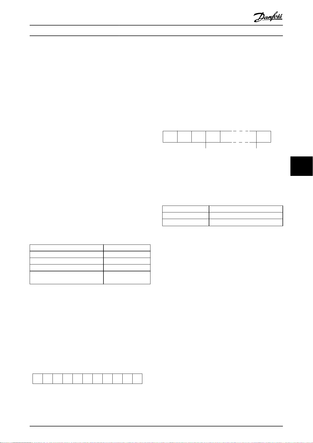
0 1 32 4 5 6 7
195NA036.10
Bit di
start
Parità Bit di
stop
STX LGE ADR DATA BCC
195NA099.10
RS485 安装和设置 设计指南
7.2.2 带 Modbus RTU 的 FC
FC 协议提供了访问变频器的控制字和总线参考值的能
力。
Modbus 主站可以借助控制字来控制若干重要的变频器功
能:
启动。
•
以多种方式停止变频器:
•
- 惯性停止。
- 快速停止。
- 直流制动停止。
- 正常(变速)停止。
故障跳闸后复位。
•
以各种预置速度运转。
•
反向运转。
•
有效菜单的更改。
•
控制变频器内置的 2 个继电器。
•
总线参考值通常用于速度控制。此外还可以访问参数,读
取其值,如果可能还可以将值写入其中。借助访问参数,
可以使用一系列的控制选项,包括在使用变频器的内部
PID 控制器时,控制变频器的给定值。
启动协议的参数设置
7.3
7.4.2 报文结构
每个报文都具有下列结构:
起始字符 (STX)=02 hex。
•
一个字节表示报文长度 (LGE)。
•
一个字节指明变频器地址 (ADR)。
•
接着是若干数据字节(数量不定,具体取决于电报的类
型)。
报文以一个数据控制字节 (BCC) 作为结束。
图 7.5 报文结构
7.4.3 报文长度 (LGE)
报文长度是数据字节、地址字节 ADR 以及数据控制字节
BCC 三者之和。
4 个数据字节 LGE = 4+1+1=6 个字节
12 个数据字节 LGE = 12+1+1=14 个字节
含有文本的报文
101)+n 字节
7 7
要启用变频器的 FC 协议,请设置下述参数。
参数 设置
参数 8-30 协议
参数 8-31 地址
参数 8-32 波特率
参数 8-33 奇偶校验/停止位
表 7.3 启用协议的参数设置
FC 协议消息帧结构
7.4
FC
1–126
2400–115200
偶校验,1 个停止位
(默认)
7.4.1 字符(字节)的内容
每个字符的传输都是从该字符的起始位开始。随后传输 8
个数据位,对应一个字节。每个字符都通过奇偶校验位得
到保护。当该位符合奇偶校验时,它被设为 1。奇偶校验
是指 8 个数据位和该奇偶校验位中的 1 的个数在总体上
相等。字符以停止位作为结束,因此,一个字符共包括
11 位。
表 7.4 报文长度
1) 10 表示固定字符数,而 n 是可变的(取决于文本的长
度)。
7.4.4 变频器地址 (ADR)
地址格式 1-126
位 7=1(使用 1-126 的地址格式)。
•
位 0-6=变频器地址 1-126。
•
位 0-6 = 0 广播。
•
从系统在对主系统的响应报文中会原封不动地将地址字节
发回。
7.4.5 数据 控制字节 (BCC)
校验和是以 XOR 函数形式计算的。收到报文的第一个字
节之前,所求出的校验和为 0。
图 7.4 字符内容
MG18C841 Danfoss A/S © 04/2018 全权所有。 79
Page 82

ADRLGESTX PCD1 PCD2 BCC
130BA269.10
PKE INDADRLGESTX PCD1 PCD2 BCC
130BA271.10
PWE
high
PWE
low
PKE IND
130BA270.10
ADRLGESTX PCD1 PCD2 BCCCh1 Ch2 Chn
15 14 13 12 11 10 9 8 7 6 5 4 3 2 1 0
130BB918.10
PKE IND
PWE
high
PWE
low
AK PNU
Parameter
commands
and replies
Parameter
number
RS485 安装和设置
VLT® HVAC Basic Drive FC 101
7.4.6 数据字段
第 12-15 位用于传输参数命令(由主到从)和将从站处
理过的响应传回主站。
数据块的结构取决于报文类型。有 3 种类型的电报,每
种电报类型都同时适用于控制电报(由主⇒从)和响应电
报(由从⇒主)。
这 3 种报文类型是:
过程块 (PCD)
PCD 由 4 个字节(2 个字)的数据块组成,其中包括:
控制字和参考值(由主到从)。
•
状态字和当前输出频率(由从到主)。
•
图 7.6 过程块
77
参数块
参数块用于在主站和从站之间传输参数。数据块由 12 个
字节(6 个字)组成,并且还包含过程块。
图 7.7 参数块
位编号 参数命令
15 14 13 12
0 0 0 0 无命令。
0 0 0 1 读取参数值。
0 0 1 0 将参数值写入 RAM(字)。
0 0 1 1 将参数值写入 RAM(双字)。
1 1 0 1
1 1 1 0 将参数值写入 RAM 和 EEPROM(字)。
1 1 1 1 读取文本。
表 7.5 参数命令
位编号 响应
15 14 13 12
0 0 0 0 无响应。
0 0 0 1 传输的参数值(字)。
0 0 1 0 传输的参数值(双字)。
0 1 1 1 命令无法执行。
1 1 1 1 传输的文本。
主 ⇒ 从的参数命令。
将参数值写入 RAM 和 EEPROM(双
字)。
从⇒主的响应
文本块
文本块用于通过数据块读取或写入文本。
图 7.8 文本块
7.4.7 PKE 字段
PKE 字段包含 2 个子字段:
•
•
图 7.9 PKE 字段
参数命令和响应 (AK)
参数号 (PNU)
表 7.6 响应
如果命令无法执行,从站发出响应消息“
执行
”,并在
故障代码 FC+ 规范
>100 –
表 7.7
中给出下述故障报告:
0 非法参数编号。
1 参数无法被更改。
2 超出上限或下限。
3 子索引损坏。
4 无数组。
5 错误的数据类型。
6 未使用。
7 未使用。
9 描述元素不可用。
11 没有参数写访问权限。
15 没有可用文本。
17 不能在运行时进行。
18 其他错误。
100 –
130 此参数不能通过总线访问。
131 无法写入到出厂设置。
132 LCP 无访问权限。
252 未知查看器。
253 请求不受支持。
254 未知属性。
0111 命令无法
80 Danfoss A/S © 04/2018 全权所有。 MG18C841
Page 83

RS485 安装和设置 设计指南
故障代码 FC+ 规范
255 无错误。
表 7.7 从站报告
7.4.8 参数号 (PNU)
第 0 - 11 位用于传输参数号。在
中定义了有关参数的功能。
章 6 编程
的参数说明
7.4.9 索引 (IND)
同时使用索引和参数号,可以对具有索引的参数(如 )
进行读/写访问,例如
代码
。索引包含 2 个字节: 1 个低位字节和 1 个高位
字节。
只有低位字节可作为索引使用。
参数 15-30 报警记录: 故障错误
7.4.10 参数值 (PWE)
参数值块由 2 个字(4 个字节)组成,其值取决于定义
的命令 (AK)。当 PWE 块不包含任何值时,主站会提示您
输入参数值。要更改某个参数值(写操作),请将新值写
入 PWE 块中,然后从主站将相关消息发送到从站。
数据类型 说明
9 文本字符串
表 7.8 数据类型
7.4.12 转换
编程指南
数形式传输。在传输小数时需要使用转换因数。
参数 4-12 电机速度下限 [Hz]
将最小频率预设为 10 Hz,则传输的值应是 100。如果转
换因数为 0.1,则表示被传输的值将被乘以 0.1。因此,
如果传输的值为 100,将被认为是 10.0。
包含每个参数的属性的说明。参数值只能以整
的转换因数为 0.1。要
转换索引 转换因数
74 3600
2 100
1 10
0 1
-1 0.1
-2 0.01
-3 0.001
-4 0.0001
-5 0.00001
7 7
如果从站对参数请求(读命令)作出了响应,PWE 块中的
当前参数值将被传回给主站。如果参数包含多个数据选项
(例如
数据值来选择相应的值。串行通讯只能读取包含数据类型
9(文本字符串)的参数。
参数 15-40 FC 类型
含数据类型 9。
例如,可以读取
主电源电压范围。在传输(读)文本字符串时,报文的长
度是可变的,因为文本具有不同的长度。报文长度在报文
的第二个字节 (LGE) 中定义。使用文本传输时,可以用
索引字符表明这是一个读命令还是一个写命令。
要通过 PWE 块读取文本,请将参数命令 (AK) 设为 F
(十六进制)。索引字符的高位字节必须为 4 。
参数 0-01 语言
到
参数 15-40 FC 类型
),则可通过在 PWE 块中输入
参数 15-53 功率卡序列号
中的设备规格和
包
7.4.11 变频器支持的数据类型
“无符号”数据类型,即在报文中没有运算符。
数据类型 说明
3 16 位整数
4 32 位整数
5 8 位无符号整数
6 16 位无符号整数
7 32 位无符号整数
表 7.9 转换
7.4.13 过程字 (PCD)
过程字的数据块分为两个部分,各有 16 位,它们总是按
照所定义的顺序出现。
PCD 1 PCD 2
控制报文(主⇒从控制字) 参考值
控制报文(从⇒主)状态字 当前的输出频率
表 7.10 过程字 (PCD)
示例
7.5
7.5.1 写入参数值
将
参数 4-14 电机速度上限 [Hz]
将数据写入 EEPROM。
PKE = E19E(十六进制)– 写入单字到
机速度上限 [Hz]
IND = 0000(十六进制)。
•
PWEHIGH = 0000(十六进制)。
•
PWELOW = 03E8(十六进制)。
•
数据值 1000,对应于 100 Hz,请参阅
换
。
:
更改为 100 Hz。
参数 4-14 电
章 7.4.12 转
MG18C841 Danfoss A/S © 04/2018 全权所有。 81
Page 84

E19E H
PKE IND PWE
high
PWE
low
0000 H 0000 H 03E8 H
130BA092.10
119E H
PKE
IND
PWE
high
PWE
low
0000 H 0000 H 03E8 H
130BA093.10
1155 H
PKE IND PWE
high
PWE
low
0000 H 0000 H 0000 H
130BA094.10
130BA267.10
1155 H
PKE
IND
0000 H 0000 H 03E8 H
PWE
high
PWE
low
RS485 安装和设置
VLT® HVAC Basic Drive FC 101
相应的报文如
图 7.10
。
Modbus RTU 概述
7.6
7.6.1 简介
Danfoss 假设所安装的控制器支持本文介绍的接口,并严
图 7.10 报文
注意
参数 4-14 电机速度上限 [Hz]
EEPROM 中写入的参数命令为“E”。
上限 [Hz]
从站对主站的响应如
是 19E(十六进制)。
图 7.11
是一个单字,用于在
参数 4-14 电机速度
所示。
77
图 7.11 主站响应
7.5.2 读取参数值
在
参数 3-41 斜坡 1 加速时间
PKE=1155(十六进制)- 读取
时间
中的参数值:
IND = 0000(十六进制)。
•
PWE
= 0000(十六进制)。
•
•
图 7.12 报文
如果
站对主站的响应如
HIGH
PWE
= 0000 Hex。
LOW
参数 3-41 斜坡 1 加速时间
图 7.13
中读取参数值
参数 3-41 斜坡 1 加速
的值为 10 秒,则从
所示。
格遵守在控制器和变频器中规定的所有要求和限制。
内置的 Modbus RTU(远程终端设备)可以与任何支持本
文定义的接口的控制器进行通讯。本说明假设用户完全了
解控制器的功能和限制。
7.6.2 概述
无论物理通讯网络为何种类型,本小节描述了控制器请求
访问另一台设备时使用的过程。这如何响应来自另一台设
备的请求,以及如何检测和报告错误。此外还建立了报文
字段布局和内容的公用格式。
在通过 ModBus RTU 网络进行通讯期间,协议将:
确定每个控制器将如何了解其设备地址。
•
如何识别发送给它的报文。
•
如何确定要采取的操作。
•
如何提取报文中所含的任何数据或其他信息。
•
如果要求回复,控制器将创建并发送回复报文。
控制器利用主从技术进行通讯,该技术仅允许主设备启动
事务(称为查询)。从设备可通过向主设备提供所请求的
数据,或按查询中请求的操作进行响应。
主站可以对单个从站进行寻址,或向所有从站发送广播报
文。从站会向对它们单独寻址的查询返回响应。但对来自
主站的广播查询则不予响应。
Modbus RTU 协议通过提供以下信息给主设备的查询建立
格式:
设备(或广播)地址。
•
定义所需操作的功能代码。
•
将发送的任何数据。
•
错误检查字段。
•
也可使用 Modbus 协议创建从站的响应报文。其中包含确
认所采取操作的字段、要返回的所有数据及错误检查字
段。如果在接收报文时发生错误,或者从站无法执行所请
求的操作,那么从站将返回一条错误消息。或者出现超
时。
图 7.13 响应
3E8(十六进制)对应于 1000(十进制)。
坡 1 加速时间
参数 3-41 斜坡 1 加速时间
数
。
82 Danfoss A/S © 04/2018 全权所有。 MG18C841
的转换索引为 -2,即 0.01。
的类型是
无符号 32 位整
参数 3-41 斜
7.6.3 带有 Modbus RTU 的变频器
该变频器通过内置的 RS485 接口以 Modbus RTU 格式进
行通讯。Modbus RTU 提供了访问变频器的控制字和总线
参考值的能力。
Page 85
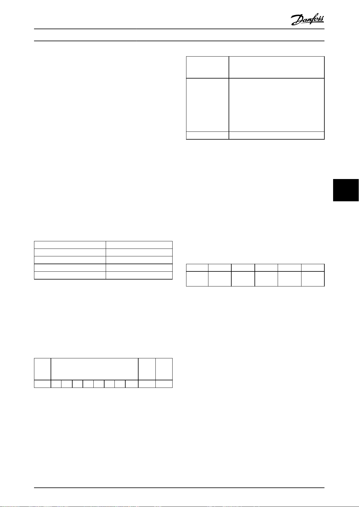
RS485 安装和设置 设计指南
Modbus 主站可以借助控制字来控制若干重要的变频器功
能:
启动。
•
多种停止:
•
- 惯性停止。
- 快速停止。
- 直流制动停止。
- 正常(变速)停止。
故障跳闸后复位。
•
以各种预置速度运转。
•
反向运转。
•
更改有效菜单。
•
控制变频器的内置继电器。
•
总线参考值通常用于速度控制。此外还可以访问参数,读
取其值,如果可能还可以将值写入其中。借助访问参数,
可以使用一系列的控制选项,包括在使用变频器的内部
PID 控制器时,控制变频器的给定值。
7.7 网络配置
要在该变频器上启用 Modbus RTU,请设置下述参数:
参数 设置
参数 8-30 协议
参数 8-31 地址
参数 8-32 波特率
参数 8-33 奇偶校验/停止位
表 7.11 网络配置
Modbus RTU 消息帧结构
7.8
Modbus RTU
1–247
2400–115200
偶校验,1 个停止位(默认)
7.8.1 简介
控制器被设置为在 Modbus 网络上使用 RTU(远程终端设
备)模式进行通讯,消息中的每个字节中都包含两个 4
位十六进制字符。各个字节的格式如
起始
位
表 7.12 各个字节的格式
数据字节 停止/
表 7.12
所示。
停止
奇偶校
验
编码系统 8 位,二进制、十六进制 0–9, A–F。
在报文的每个 8 位字段中都包括 2 个十
六进制字符。
每个字节的位数
错误检查字段 循环冗余校验 (CRC)。
表 7.13 字节详情
1 个起始位。
•
8 个数据位,最小有效位先发送。
•
1 个偶/奇校验位; 如果无奇偶校验,
•
则不存在位。
1 个停止位(如果使用奇偶校验);
•
如果无奇偶校验,则为 2 位。
7.8.2 Modbus RTU 报文结构
传输设备将 Modbus RTU 报文放入一个 开始和结束位置
已知的帧中。这样,即可在报文开始处指定接收设备,读
取地址部分,确定该报文要发送到哪台设备(或所有设
备,如果报文为广播型),并了解报文的完成时间。检测
到部分报文,因而产生错误。在每个字段中传输的字符必
须使用从 00–FF 的十六进制格式。变频器会持续监视网
络总线,即便在静止期间也是如此。接收到第一个字段
(地址字段)后,每个变频器或设备都会将其解码,以确
定被寻址的设备。编址为零的 Modbus RTU 报文是广播报
文。不允许响应广播报文。典型的报文帧如
示。
开始时) 地址 功能 数据 CRC 检查 终止
T1-T2-
T3-T4
表 7.14 典型 Modbus RTU 报文结构
8 位 8 位
N x 8
位
表 7.14
16 位
所
T1-T2-
T3-T4
7.8.3 启动/停止字段
报文以一个静止段开始。此段至少为 3.5 个字符间隔。
静止段为多个字符间隔,这可用所选网络波特率下的字符
间隔的倍数来实现(显示为启动 T1-T2-T3-T4)。所传输
的第一个字段为设备地址。在传输完最后一个字符后,紧
接着是一个类似的至少为 3.5 个字符间隔的段,它标志
着报文的结束。在此段之后可以开始新的报文。
将整个报文帧作为连续的数据流传输。如果在帧结束之前
出现了超过 1.5 个字符间隔的静止段,则接收设备会丢
弃不完整的报文,并假设下一字节为新报文的地址字段。
类似地,如果新报文在上一条报文之后的 3.5 个字符间
隔内便开始,则接收设备会将其视为上一报文的延续。这
会导致超时(从站无响应),因为对于该组合报文而言,
最后的 CRC 字段中的值将无效。
7 7
MG18C841 Danfoss A/S © 04/2018 全权所有。 83
Page 86
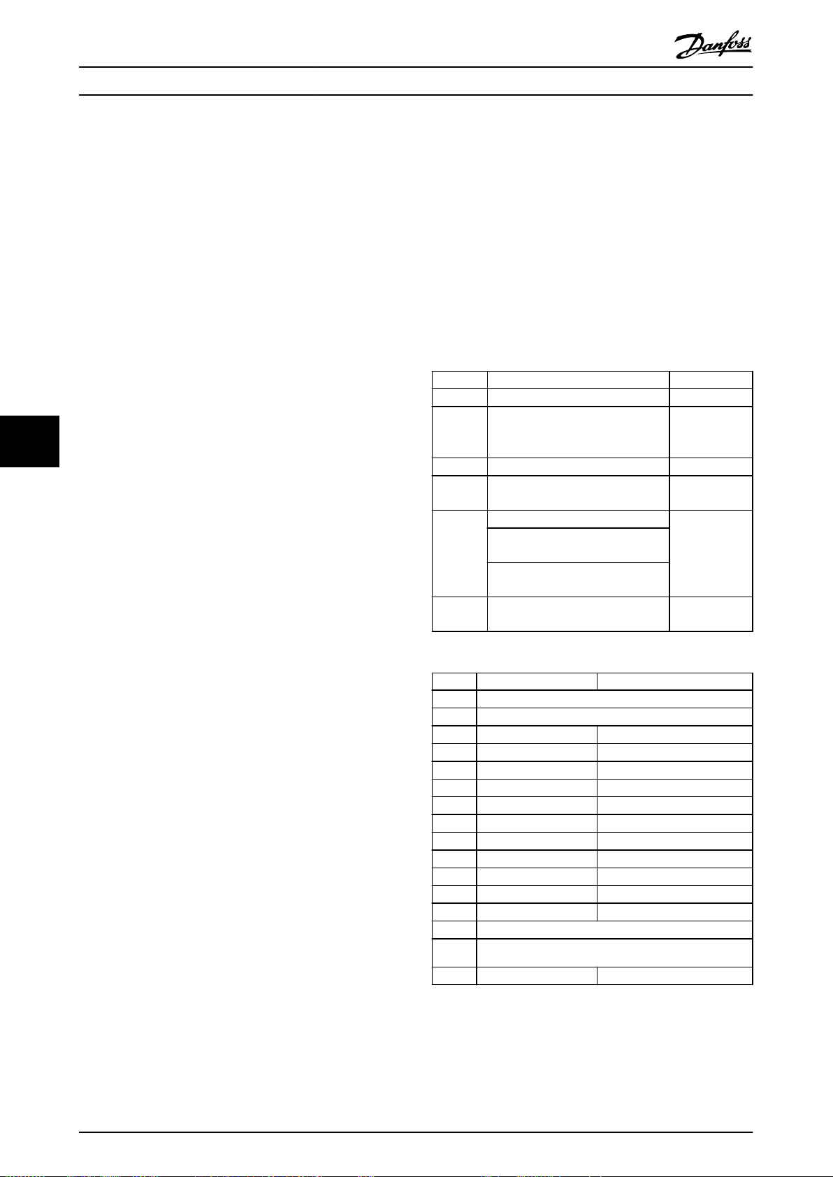
RS485 安装和设置
VLT® HVAC Basic Drive FC 101
7.8.4 地址字段
报文帧的地址字段包含 8 位。有效的从设备地址应介于
0–247(十进制) 范围内。为单台从设备分配的地址应
介于 1–247 的范围。0 预留给广播模式,这是所有从站
都认可的。主站通过将从站地址放入报文的地址字段,对
从站进行寻址。从站发送其响应时,会将自己的地址放在
此地址字段中,以使主站了解哪个从站在进行响应。
7.8.8 线圈寄存器编址
在 Modbus 中,所有数据都是用线圈和保持寄存器来组织
的。线圈保持单个位,而保持寄存器则保持 2 字节字
(即 16 位)。Modbus 报文中的所有数据地址均从零开
始。数据项的第一个项目编号被编址为零。例如: 可编
程控制器中的线圈 1 在 Modbus 报文的数据地址字段中
被编址为线圈 0000。线圈 127(十进制)被编址为线圈
007EHEX(十进制的 126)。
7.8.5 功能字段
保持寄存器 40001 在报文数据地址字段中被编址为寄存
器 0000。功能代码字段已指定某个保持寄存器操作。因
报文帧的功能字段包含 8 位。有效代码的范围为 1 FF。功能字段用于在主站和从站之间发送报文。从主设备
此,4XXXX 引用值是固有的。保持寄存器 40108 被编址
为寄存器 006BHEX(十进制的 107)。
向从属设备发送报文时,功能代码字段将通知从属设备要
执行的操作类型。从属设备对主设备进行响应时,会使用
功能代码字段指示正常(无错)响应或发生了某种错误
(称为异常响应)。
77
对于正常响应,从属设备只重复原先的功能代码。对于异
常响应,从站会返回一个代码。该代码相当于原始的功能
代码,只不过其最大有效位被设为逻辑 1。此外,从属设
备还将一个唯一的代码放入响应报文的数据字段中。该代
码可通知主控制器发生了哪种错误,或异常的原因。另请
参阅
章 7.8.11 Modbus RTU 支持的功能代码
章 7.8.12 Modbus 异常代码
。
和
7.8.6 数据字段
数据字段是使用几组两个十六进制数字(范围在 00 至
FF 之间)构建的。这些数字都由一个 RTU 字符构成。从
主设备发送到从设备的报文的数据字段包含其他信息,从
属设备必须使用这些信息执行相应功能。
该信息可包括以下项目:
线圈或寄存器地址。
•
要处理的项目数量。
•
字段内的实际数据字节数。
•
7.8.7 CRC 检查字段
报文中包括一个错误检查字段,此字段的工作机制基于循
环冗余校验 (CRC) 方法。CRC 字段可检查整条报文的内
容。它的应用与用于报文的单个字符的任何奇偶校验方法
均无关。传输设备计算 CRC 值,然后将 CRC 作为最后一
个字段附加在报文中。接收设备会在接收报文过程中重新
计算 CRC,并将计算值与 CRC 字段中接收到的实际值相
比较。2 个值不相等将会导致总线超时。错误检查字段包
含一个 16 位二进制值,该值由两个 8 位字节组成。执
行之后,首先附加字段的低位字节,然后是高位字节。CRC
高位字节为报文中发送的最后一个字节。
线圈编号 说明 信号方向
1–16 变频器控制字(请参阅
变频 器速度或给定-值的 参考 范
17–32
33–48 变频器状态字(请参阅
49–64
65536
表 7.15 线圈寄存器
线圈 0 1
表 7.16 变频器控制字(FC 协议)
围 0x0–0xFFFF (-200% ...
~200%)。
开环模式: 变频器输出频率。
闭环模式: 变频器反馈信号。
参数写入控制(由主到从)。
0 = 将参数变化写入变频器的
65
RAM。
1 = 将参数变化写入变频器的 RAM
和 EEPROM。
66–
预留。 –
01 预置参考值,低位 (lsb)
02 预置参考值,高位 (msb)
03 直流制动 无直流制动
04 惯性停止 无惯性停止
05 快速停止 无快速停止
06 锁定频率 无锁定频率
07 加减速停止 开始时)
08 不复位 复位
09 无点动 点动
10 加减速 1 加减速 2
11 数据无效 数据有效
12 继电器 1 关 继电器 1 开
13 继电器 2 关 继电器 2 开
14 设置 lsb
15 –
16 无反向 反向
表 7.16
表 7.17
) 由主到从
由主到从
)。 由从到主
由从到主
由主到从
84 Danfoss A/S © 04/2018 全权所有。 MG18C841
Page 87

RS485 安装和设置 设计指南
线圈 0 1
33 控制未就绪 控制就绪
34 变频器未就绪 变频器就绪
35 惯性停止 安全功能关闭
36 无报警 报警
37 未使用 未使用
38 未使用 未使用
39 未使用 未使用
40 无警告 警告
41 不在参考值下 在参考值下
42 手动模式 自动模式
43 超出频率范围 在频率范围内
44 已停止 运行
45 未使用 未使用
46 无电压警告 电压超过
47 不在电流极限内 电流极限
48 热负载正常 热负载超过极限
表 7.17 变频器状态字(FC 协议)
总线
总线
地址
0 1 40001 预留 –
1 2 40002 预留 –
2 3 40003 预留 –
3 4 40004 自由 – –
4 5 40005 自由 – –
5 6 40006 Modbus 配置
6 7 40007 最近的故障代码 只读 从参数数据库收到的故障代码,有关详细信息,请参考 WHAT 38295。
7 8 40008 最近的错误寄存器 只读 最近发生错误的寄存器的地址,有关详细信息,请参考 WHAT 38296。
8 9 40009 索引指针
9 10 40010
19 20 40020 自由 – –
29 30 40030
表 7.18 地址/寄存器
1) 写入 Modbus RTU 报文的值必须为 1 或小于寄存器编号。例如,可通过在报文中写入值 0 来读取 Modbus 寄存器 1。
寄存
器
1)
PLC 寄存
器
内容 访问 说明
预留给早期的 VLT® 5000 和 VLT® 2800 变频器。
预留给早期的 VLT® 5000 和 VLT® 2800 变频器。
预留给早期的 VLT® 5000 和 VLT® 2800 变频器。
参数 0-01 语言
参数 0-03 区域性设
置
读/写
(R/W)
读/写
(R/W)
取决于参数
访问权限
取决于参数
访问权限
仅限 TCP。预留给 Modbus TCP(
数 12-29 总是存储
要访问的参数的下标索引。有关详细信息,请参考 WHAT 38297。
参数 0-01 语言
为 Modbus 映射中的 pr 参数预留 20 个字节的空间。
参数 0-03 区域性设置
为 Modbus 映射中的 pr 参数预留 20 个字节的空间。
(Modbus 寄存器 = 10 个参数编号)
参数 12-28 存储数据值
- 存储在诸如 EEPROM 等位置内)。
和
7 7
参
7.8.9 通过 PCD 读/写访问
注意
控制字和参考值始终通过该列表从控制器发送到变频器。
使用 PCD 读/写配置的好处是控制器可在一个报文中写入
或读取更多数据。通过功能代码读取保持寄存器或在一个
PCD 写入列表在
参数 8-42 PCD 写配置
中设置。
报文中写入多个寄存器,最多可读写 63 个寄存器。结构
还很灵活,可以只写入 2 个寄存器,而从控制器读取 10
个寄存器。
PCD 读取列表是从变频器发送到控制器的数据,比如状态
字、主实际值以及应用程序相关数据,比如运行时间、电
机电流和报警字。
PCD 写入列表是从控制器发送到变频器的数据,这些数据
包括控制字、参考值和应用相关数据,比如最小参考值和
加减速时间等。
注意
状态字和主实际值始终通过该列表从变频器发送到控制
器。
MG18C841 Danfoss A/S © 04/2018 全权所有。 85
Page 88

CTW
Holding
Register
2810
Write
Master Frequency Converter
Read
Frequency
Converter Master
Controlled by
Parameter
Holding
Register
Controlled by
Parameter
8-42 [0]
REF
2811
8-42 [1]
2812
8-42 [2]
PCD 2
write
2813
8-42 [3]
PCD 3
write
2814
8-42 [4]
PCD 4
write
2815
8-42 [5]
PCD 5
write
...
...
...
write
2873
8-42 [63]
PCD 63
write
STW
2910
8-43 [0]
MAV
2911
8-43 [1]
2912
8-43 [2]
PCD 2
read
2913
8-43 [3]
PCD 3
read
2914
8-43 [4]
PCD 4
read
2915
8-43 [5]
PCD 5
read
...
...
...
read
2919
8-43 [63]
PCD 63
read
130BC048.10
RS485 安装和设置
VLT® HVAC Basic Drive FC 101
77
图 7.14 通过 PCD 读/写访问
注意
标记为灰色的框不可更改,它们是默认值。
注意
32 位参数必须在 32 位边界(PCD2 和 PCD3 或 PCD4
和 PCD5 等),其中,参数编号被映射两次至
数 8-42 PCD 写配置
7.8.10 如何控制变频器
本节介绍了可以在 Modbus RTU 报文的功能字段和数据字
段中使用的代码。
7.8.11 Modbus RTU 支持的功能代码
Modbus RTU 支持在报文的功能字段中使用下述功能代
码。
读取线圈 1
读取保持寄存器 3
写入单个线圈 5
写入单个寄存器 6
写入多个线圈 F
写入多个寄存器 10
获取通讯事件计数器 B
报告从站 ID 11
读写多个寄存器 17
表 7.19 功能代码
参
或
参数 8-43 PCD 读配置
功能 功能代码 (十六进制)
。
功能 功能代码
子功能
代码
子功能
1 重新启动通讯。
2 返回诊断寄存器。
清空计数器和诊断寄存
10
诊断 8
器。
11 返回总线消息计数。
12 返回总线通讯错误计数。
13 返回从站错误计数。
14 返回从站消息计数。
表 7.20 功能代码
7.8.12 Modbus 异常代码
有关异常代码响应消息的结构的完整说明,请参考
章 7.8.5 功能字段
代码 名称 含义
1 非法功能
2 非法数据地址
3 非法数据值
从设备发生故障伺服设备(或从设备)尝试执行请求操作
4
表 7.21 Modbus 异常代码
如何访问参数
7.9
。
查询中收到的功能代码对于该伺服设备
(或从设备)来说是不允许的操作。这可
能是因为该功能代码仅适用于更新的设
备,未在所选设备中实施。这可能还表明
该伺服设备(或从设备)处于错误状态
下,无法处理此类型的请求,原因可能是
未进行配置,或未被要求返回寄存器值。
查询中收到的数据地址对于该伺服设备
(或从设备)来说是不允许的地址。更为
具体来说,参照编号和传输长度的组合无
效。对于具有 100 个寄存器的控制器来
说,偏差为 96,长度为 4 的请求成
功,偏差为 96 长度为 5 的请求则会产
生异常 02。
查询数据中包含的值对于该伺服设备(或
从设备)来说是不允许的值。这表明一个
复杂请求的提示内容结构有问题,如隐含
的长度不正确。而不是表示提交用于存储
在寄存器中的数据项的值超出应用程序的
范围,因为 Modbus 协议并不知道任何寄
存器的任何值的重要性。
时发生不可恢复的错误。
7.9.1 参数处理
PNU(参数号)是从 Modbus 读/写消息中包含的寄存器地
址转换而来的。参数号以十进制 形式转换为 Modbus 格
式(10 x 参数号)。范例: 读取
速值
(16 位): 保持寄存器 3120 存放参数值。值为
1352(十进制)表示该参数被设置为 12.52%。
参数 3-12 加速/减
86 Danfoss A/S © 04/2018 全权所有。 MG18C841
Page 89
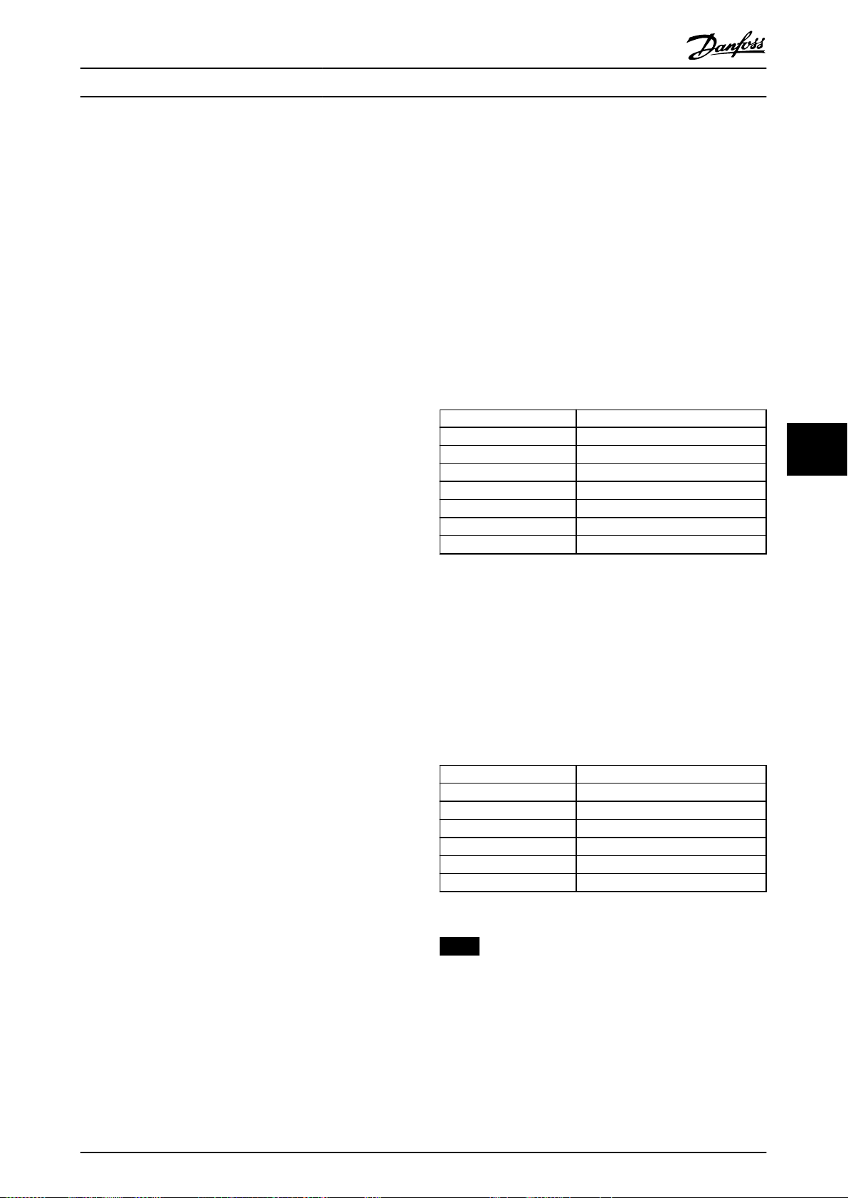
RS485 安装和设置 设计指南
读取
参数 3-14 预置相对参考值
器 3410 和 3411 存放参数值。值为 11300(十进制)
表示该参数被设置为 1113.00。
(32 位): 保持寄存
7.10
下述示例显示了各种 Modbus RTU 命令。
示例
有关参数、大小和转换索引的信息,请参阅
章 6 编程
。
7.9.2 数据存储
线圈 65(十进制)可决定是将写入变频器的数据存储到
EEPROM 和 RAM(线圈 65=1) 还是仅存储到 RAM 中(线
圈 65=0)。
7.9.3 IND(索引)
变频器中的一些参数是数组参数,如
值
。由于 Modbus 不支持在保持寄存器中存放数组,变频
器将保持寄存器 9 保留用作数组指针。读取或写入一个
数组参数前,设置保持寄存器 9。将保持寄存器设置为值
2,将导致所有后续的读取/写入数组参数的操作都使用索
引 2。
参数 3-10 预置参考
7.9.4 文本块
可以像访问其他参数那样访问以文本字符串形式存储的参
数。文本块的最大长度为 20 个字符。在对某个参数的读
请求中,如果请求的字符数超过该参数存储的字符数,则
响应消息会被截断。在对某个参数的读请求中,如果请求
的字符数少于该参数存储的字符数,则会用空格填充响应
消息。
7.9.5 转换因数
参数值只能以整数的形式传输。若要传输小数,请使用转
换因数。
7.10.1 读取线圈状态(01 [十六进制])
说明
该功能读取变频器中离散输出(线圈)的开/关状态。读取
操作从不支持广播。
查询
查询报文指定起始线圈和要读取的线圈数。线圈地址从 0
开始,如线圈 33 的地址应为 32。
从“从站设备 01”读取线圈 33 - 48 (状态字)的请
求示例。
字段名称 示例(十六进制)
从站地址 01(变频器地址)
功能 01(读取线圈)
起始地址,高位 00
起始地址,低位 20(十进制的 32)线圈 33
固定点数量,高位 00
固定点数量,低位 10(十进制的 16)
错误检查 (CRC) –
表 7.22 查询
响应
按照数据字段中每位一个线圈的形式,对响应报文中的线
圈状态进行打包。状态指示如下: 1 = ON; 0 = OFF。
第一个数据字节的 LSB 包含在查询中寻址的线圈。其他
线圈跟在该字节的高位端之后,并按从“低位到高位”的
顺序出现在后续字节中。
如果返回的线圈数量不是 8 的倍数,则将用零填充最后
的数据字节中的其余位(向该字节的高位端填充)。“字
节数”字段指定数据的完整字节数。
7 7
7.9.6 参数值
标准数据类型
标准数据类型有 int 16、int 32、uint 8、uint 16 和
uint 32。它们以 4x 寄存器 (40001–4FFFF) 的形式存
储。使用功能 03(十六进制)读取保持寄存器 可读取这
些参数。使用以下功能可写入参数:对于 1 个寄存器
(16 位),使用功能 6(十六进制)预置单个寄存器;
对于 2 个寄存器(32 位),使用功能 10(十六进制)
预置多个寄存器。可读取的长度范围为 1 个寄存器(16
位)到 10 个寄存器(20 个字符)。
非标准数据类型
非标准数据类型为文本字符串,以 4x 寄存器 (40001–
4FFFF) 的形式存储。使用功能 03(十六进制)读取保持
寄存器 可读取这些参数,使用 10 (十六进制) 预置多
个寄存器 可写入这些参数 。可读取的长度范围为 1 个
寄存器(2 个字符)到 10 个寄存器(20 个字符)。
MG18C841 Danfoss A/S © 04/2018 全权所有。 87
注意
在 Modbus 中用显性偏移 -1 来访问线圈和寄存器。
比如用“线圈 32”来访问线圈 33。
字段名称 示例(十六进制)
从站地址 01(变频器地址)
功能 01(读取线圈)
字节数 02(2 字节数据)
数据(线圈 40 - 33) 07
数据(线圈 48 - 41) 06 (STW = 0607 [十六进制])
错误检查 (CRC) –
表 7.23 响应
Page 90

RS485 安装和设置
VLT® HVAC Basic Drive FC 101
7.10.2 强制/写入单个线圈(05 [十六进
制])
说明
该功能强制将线圈设为开或关。广播时,此功能强制所有
连接的从属设备均具有相同的线圈参考值。
查询
该查询报文指定对线圈 65(参数写入控制)执行强制。
线圈地址从 0 开始,如线圈 65 的地址应为 64。强制
数据 = 00 00HEX(OFF [关])或 FF 00HEX(ON
[开])。
字段名称 示例(十六进制)
从站地址 01(变频器地址)
功能 05(写入单个线圈)
线圈地址,高位 00
线圈地址,低位 40(十进制的 64)线圈 65
77
强制数据,高位 FF
强制数据,低位 00(FF 00 = 开)
错误检查 (CRC) –
表 7.24 查询
响应
正常响应是在强制线圈状态之后返回对查询的回复。
字段名称 示例(十六进制)
从站地址 01
功能 05
强制数据,高位 FF
强制数据,低位 00
线圈数量,高位 00
线圈数量,低位 01
错误检查 (CRC) –
从站地址 01(变频器地址)
功能 0F(写入多个线圈)
线圈地址,高位 00
线圈地址,低位 10(线圈地址 17)
线圈数量,高位 00
线圈数量,低位 10(16 个线圈)
字节数 02
强制数据,高位
(线圈 8-1)
强制数据,低位
(线圈 16-9)
错误检查 (CRC) –
表 7.26 查询
响应
正常响应返回从属设备地址、功能代码、起始地址和强制
线圈的数量。
从站地址 01(变频器地址)
功能 0F(写入多个线圈)
线圈地址,高位 00
线圈地址,低位 10(线圈地址 17)
线圈数量,高位 00
线圈数量,低位 10(16 个线圈)
错误检查 (CRC) –
表 7.27 响应
7.10.4 读取保持寄存器( 03 [ 十六进
字段名称 示例(十六进制)
20
00(参考值 = 2000 十六进制)
字段名称 示例(十六进制)
制])
说明
表 7.25 响应
7.10.3 强制/写入多个线圈(0F [十六进
制])
说明
该功能读取从站中保持寄存器的内容。
查询
该查询报文指定起始寄存器和要读取的寄存器数。寄存器
地址从 0 开始,如寄存器 1 - 4 的地址应为 0 - 3。
范例: 读取
参数 3-03 最大参考值
,寄存器 03030。
该功能强制一系列线圈中的每个线圈均为 ON(开)或
OFF(关)。广播时,此功能强制所有连接的从属设备均具
有相同的线圈参考值。
查询
该查询报文指定对线圈 17 - 32(速度给定值)执行强
制。
注意
线圈地址从 0 开始,如线圈 17 的地址应为 16。
字段名称 示例(十六进制)
从站地址 01
功能 03(读取保持寄存器)
起始地址,高位 0B(寄存器地址 3029)
起始地址,低位 D5(寄存器地址 3029)
固定点数量,高位 00
02 -(
固定点数量,低位
错误检查 (CRC) –
参数 3-03 最大参考值
位长,即 2 个寄存器)
为 32
表 7.28 查询
88 Danfoss A/S © 04/2018 全权所有。 MG18C841
Page 91
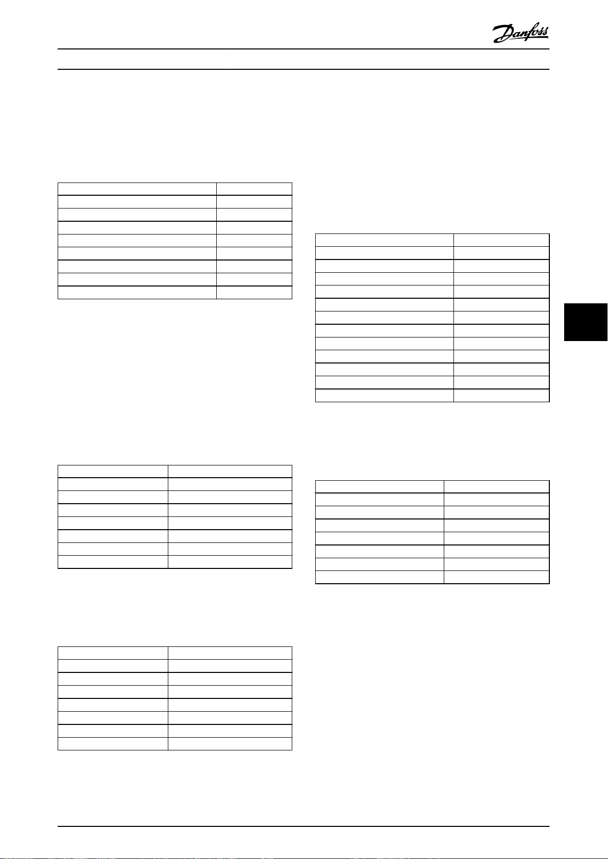
RS485 安装和设置 设计指南
响应
以每个寄存器两个字节的方式将响应报文中的寄存器数据
打包,每个字节内的二进制内容均右对齐。对于每个寄存
器,第一个字节都包含高位的位,第二个字节都包含低位
的位。
范例: 十六进制 000088B8=35.000=35 Hz。
字段名称 示例(十六进制)
从站地址 01
功能 03
字节数 04
数据,高位(寄存器 3030) 00
数据,低位(寄存器 3030) 16
数据,高位(寄存器 3031) E3
数据,低位(寄存器 3031) 60
错误检查 (CRC) –
表 7.29 响应
7.10.5 预置单个寄存器( 06 [ 十六进
制])
说明
该功能将一个值预置到单个保持寄存器中。
查询
该查询报文指定要预设的寄存器参考值。寄存器地址从 0
开始,如寄存器 1 的地址应为 0。
范例: 写入,
从站地址 01
功能 06
寄存器地址,高位 03(寄存器地址 999)
寄存器地址,低位 E7(寄存器地址 999)
预置数据,高位 00
预置数据,低位 01
错误检查 (CRC) –
表 7.30 查询
响应
正常响应是对查询的重复,在传递寄存器内容之后会被返
回。
参数 1-00 配置模式
字段名称 示例(十六进制)
寄存器 1000。
7.10.6 预置多个寄存器( 10 [ 十六进
制])
说明
该功能将值预置到一系列的保持寄存器中。
查询
该查询报文指定要预设的寄存器参考值。寄存器地址从 0
开始,如寄存器 1 的地址应为 0。下述请求示例对 2
个寄存器进行预置(将
参数 1-24 电动机电流
设置为
738 (7.38 A)):
字段名称 示例(十六进制)
从站地址 01
功能 10
起始地址,高位 04
起始地址,低位 07
寄存器数量,高位 00
寄存器数量,低位 02
字节数 04
写入数据,高位(寄存器 4: 1049) 00
写入数据,低位(寄存器 4: 1049) 00
写入数据,高位(寄存器 4: 1050) 02
写入数据,低位(寄存器 4: 1050) E2
错误检查 (CRC) –
表 7.32 查询
响应
正常响应返回从属设备地址、功能代码、起始地址和预置
的线圈数量。
字段名称 示例(十六进制)
从站地址 01
功能 10
起始地址,高位 04
起始地址,低位 19
寄存器数量,高位 00
寄存器数量,低位 02
错误检查 (CRC) –
表 7.33 响应
7.10.7 读/写多个寄存器(17 十六进制)
7 7
字段名称 示例(十六进制)
从站地址 01
功能 06
寄存器地址,高位 03
寄存器地址,低位 E7
预置数据,高位 00
预置数据,低位 01
错误检查 (CRC) –
表 7.31 响应
MG18C841 Danfoss A/S © 04/2018 全权所有。 89
说明
此功能代码将一个读取操作和一个写入操作组合到一个
MODBUS 事务中。写入操作在读取操作之前执行。
查询
该查询消息指定要读取的保持寄存器的起始地址和数量,
以及要写入的保持寄存器的起始地址、数量和要写入的数
据。保持寄存器的地址从零开始。例如,请求将
数 1-24 电动机电流
50000 (50,000 Hz) 的
设置为 738 (7.38 A) 并读取值为
参数 3-03 最大参考值
参
:
Page 92

Speed ref.CTW
Master-follower
130BA274.11
15 14 13 12 11 10 9 8 7 6 5 4 3 2 1 0
Bit
no.:
RS485 安装和设置
VLT® HVAC Basic Drive FC 101
字段名称 示例(十六进制)
从站地址 01
功能 17
读取起始地址,高位 0B(寄存器地址 3029)
读取起始地址,低位 D5(寄存器地址 3029)
读取数量,高位 00
02
读取数量,低位
写入起始地址,高位 04(寄存器地址 1239)
写入起始地址,低位 D7(寄存器地址 1239)
写入数量,高位 00
写入数量,低位 02
写入字节数 04
写入寄存器值,高位 00
写入寄存器值,低位 00
写入寄存器值,高位 02
77
写入寄存器值,低位 0E
错误检查 (CRC) –
表 7.34 查询
(
参数 3-03 最大参考值
32 位长,即 2 个寄存器)
为
响应
正常响应包含来自已读取的寄存器组的数据。“字节数”
字段指定在“读取数据”字段中读取的字节数。
字段名称 示例(十六进制)
从站地址 01
功能 17
字节数 04
读取寄存器值,高位 00
读取寄存器值,低位 00
读取寄存器值,高位 C3
读取寄存器值,低位 50
错误检查 (CRC) –
表 7.35 响应
位 位值 = 0 位值 = 1
00 参考值 外部选择低位
01 参考值 外部选择高位
02 直流制动 加减速
03 惯性停车 非惯性停车
04 快速停止 加减速
05 保持输出频率 使用斜率
06 加减速停止 开始时)
07 无功能 复位
08 无功能 点动
09 加减速 1 加减速 2
10 数据无效 数据有效
11 打开继电器 01 激活继电器 01
12 打开继电器 02 激活继电器 02
13 参数设置 选择低位
15 无功能 反向
表 7.36 与 FC 协议对应的控制字
关于控制位的说明
位 00/01
位 00 和 01 用于在根据
参考值
中预设的四个参考值之间选择。
预设的参考值 参数
1
2
3
4
表 7.37 控制位
参数 3-10 预置参考值
参数 3-10 预置参考值
参数 3-10 预置参考值
参数 3-10 预置参考值
表 7.37
在
[0] 0 0
[1] 0 1
[2] 1 0
[3] 1 1
注意
使用
参数 8-56 预置参考值选择
何与数字输入上的对应功能进行门运算。
可以定义位 00/01 如
参数 3-10 预置
位01位
00
7.11
7.11.1 与 FC 协议对应的控制字(参数
图 7.15 与 FC 协议对应的控制字
90 Danfoss A/S © 04/2018 全权所有。 MG18C841
Danfoss FC 控制协议
8-10 协议 = FC 协议)
位 02,直流制动
位 02 = 0: 导致直流制动和停止。制动电流和制动时间
分别在
动时间
参数 2-01 直流制动电流
中设置。
和
参数 2-02 直流制
位 02 = 1: 导致加减速。
位 03,惯性停车
位 03 = 0: 变频器会立即释放电动机(关闭输出晶体
管),从而使电动机惯性运转直至停止。
位 03 = 1: 如果满足其他启动条件,变频器将启动电
机。
在
参数 8-50 选择惯性停车
中,可以定义位 03 如何
与数字输入上的对应功能进行门运算。
位 04,快速停止
位 04 = 0: 使电动机减速至停止(在
减速时间
中设置)。
参数 3-81 快停
Page 93

Output frequencySTW
Bit
Slave-master
15 14 13 12 11 10 9 8 7 6 5 4 3 2 1 0
130BA273.12
RS485 安装和设置 设计指南
位 05,保持输出频率
位 05 = 0: 锁定当前的输出频率(单位为 Hz)。只能
通过将数字输入(
数 5-13 端子 29 数字输入
[22] 减速
参数 5-10 端子 18 数字输入
)设置为
来更改锁定的输出频率。
[21] 加速
到
和
参
注意
如果激活锁定输出功能,则只能用下述方式之一停止变频
器:
位 03 惯性停止。
•
位 02,直流制动。
•
数字输入设置为
•
性停车反逻辑 或 [3] 慣性停车和复位反逻辑
(
参数 5-10 端子 18 数字输入
数 5-13 端子 29 数字输入
位 06,加减速停止/启动:
位 06 = 0: 将导致停止。在此期间,电机会根据所选择
的减速参数减速至停止。
位 06 = 1: 如果满足其他启动条件,则位 06 允许变
频器启动电机。
通过在
参数 8-53 启动选择
(加减速停止/启动)如何与数字输入上的对应功能进行门
运算。
位 07,复位
位 07 = 0: 不复位。
位 07 = 1: 将跳闸复位。复位是在信号的前沿被激活,
即从逻辑 0 变为逻辑 1 时。
位 08,点动
位 08 = 1:
率。
位 09,选择加减速 1/2
位 09 = 0: 启用加减速 1(
间
到
位 09 = 1: 启用加减速 2(
间
到
位 10,数据无效/数据有效
通知变频器使用或忽略控制字。
位 10 = 0: 忽略控制字。
位 10 = 1: 使用控制字。由于不论电报类型为何,电报
始终都包含控制字,因此该功能具有普遍意义。如果更新
或读取参数时无需控制字,则将它关闭。
位 11,继电器 01
位 11 = 0: 不激活继电器。
位 11 = 1: 如果在
[36] 控制字位 11
位 12,继电器 02
位 12 = 0: 继电器 02 未激活。
位 12 = 1: 如果在
[37] 控制字位 12,则激活继电器 02。
参数 3-11 点动速度 [Hz]
参数 3-42 斜坡 1 减速时间
参数 3-52 斜坡 2 减速时间
,则激活继电器 01。
[5] 直流制动反逻辑、[2] 惯
至
)。
中进行选择,可以定义位 06
确定输出频
参数 3-41 斜坡 1 加速时
)。
参数 3-51 斜坡 2 加速时
)。
参数 5-40 继电器功能
参数 5-40 继电器功能
参
中选择了
中选择了
位 13,设置选择
使用位 13,可根据
选择。
表 7.38 菜单设置
只有在
参数 0-10 有效设置
才能使用该功能。
使用
参数 8-55 菜单选择
输入端上的对应功能进行门运算。
位 15 反向
位 15 = 0: 不反转。
位 15 = 1: 反向。默认设置下,反转功能在
数 8-54 反向选择
行通讯、
致反向。
[2] 逻辑或或 [3]逻辑与
表 7.38
设置 位 13
1 0
2 1
中被设为数字方式。只有在选择了串
在 2 个菜单设置之间进行
中选择了 [9] 多重菜单,
可以定义位 13 如何与数字
时,位 15 才能导
参
7.11.2 同 FC 协议对应的状态字 (STW)
将
参数 8-30 协议
图 7.16 状态字
位 位 = 0 位 = 1
00 控制未就绪 控制就绪
01 变频器未就绪 变频器就绪
02 惯性停车 启用
03 无错误 跳闸
04 无错误 错误(无跳闸)
05 预留 –
06 无错误 锁定性跳闸
07 无警告 警告
速度 ≠ 参考值
08
09 本地运行 总线控制
10 超出频率极限 频率极限正常
11 无功能 运行
12 变频器正常 停止,自动启动
13 电压正常 过压
14 电流正常 超过电流
15 热负载正常 热负载超过极限
设置为
[0] FC
。
速度 = 参考值
7 7
MG18C841 Danfoss A/S © 04/2018 全权所有。 91
表 7.39 同 FC 协议对应的状态字
Page 94

RS485 安装和设置
VLT® HVAC Basic Drive FC 101
关于状态位的说明
位 00,控制未就绪/就绪
位 00 = 0: 此后变频器将跳闸。
位 00 = 1: 变频器控制系统已就绪,但不一定已为电源
单元供电(针对控制系统外接 24V 电源的情形)。
位 01,变频器就绪
位 01 = 0: 变频器未就绪。
位 01 = 1: 变频器已作好运行准备,但通过数字输入或
串行通讯激活了惯性停车命令。
位 02,惯性停止
位 02 = 0: 变频器释放电动机。
位 02 = 1: 变频器通过启动命令启动电动机。
位 03,无错误/跳闸
位 03 = 0: 变频器不在故障模式下。
位 03 = 1: 此后变频器将跳闸。要恢复运行,请按
[Reset](复位)。
位 13,电压正常/超过极限:
位 13 = 0: 没有电压警告。
位 13 = 1: 变频器直流回路中的直流电压过低或过高。
位 14,电流正常/超过限制
位 14 = 0: 电动机电流低于在
Limit
中选择的电流极限。
位 14 = 1: 超过
极限。
位 15,热负载正常/超过极限
位 15 = 0: 电动机热保护和热保护的计时器尚未超过
100%。
位 15 = 1: 其中的一个定时器超过了 100%。
参数 4-18 Current Limit
参数 4-18 Current
中的电流
77
位 04,无错误/错误(无跳闸)
位 04 = 0: 变频器不在故障模式下。
位 04 = 1: 变频器显示了一个错误,但没有跳闸。
位 05,未使用
在状态字中不使用位 05。
位 06,无错误/锁定性跳闸
位 06 = 0: 变频器不在故障模式下。
位 06 = 1: 变频器跳闸,并且被锁定。
位 07,无警告/警告
位 07 = 0: 没有警告。
位 07 = 1: 发生一个警告。
位 08,速度 ≠ 参考值/速度 = 参考值
位 08 = 0: 电机在运行,但其当前速度与预置的速度参
考值不同。在启动/停止期间加减速时,可能出现这种情
形。
位 08 = 1: 电动机速度符合预置的速度参考值。
位 09,本地运行/总线控制
位 09 = 0: 在控制单元上激活了 [Off/Reset](停止/
复位),或者在
本地控制。不能通过串行通讯控制变频器。
位 09 = 1: 可以通过现场总线/串行通讯来控制变频
器。
位 10,超出频率极限
位 10 = 0: 输出频率达到在
限 [Hz]
值。
位 10 = 1: 输出频率在定义的极限范围内。
位 11,未运行/运行
位 11 = 0: 电动机未运行。
位 11 = 1: 变频器有启动信号,无惯性停车。
位 12,变频器正常/已停止,自动启动
位 12 = 0: 变频器无暂时性过热。
位 12 = 1: 变频器因过热而停止,但设备并未跳闸,因
此,一旦温度恢复正常,仍可继续工作。
或
参数 3-13 参考值位置
中选择了[2]
参数 4-12 电动机速度下
参数 4-14 电动机速度上限 [Hz]
中设置的
92 Danfoss A/S © 04/2018 全权所有。 MG18C841
Page 95

Actual output
frequency
STW
Follower-slave
Speed referenceCTW
Master-slave
16bit
130BA276.11
Reverse Forward
Par.3-00 set to
(1) -max- +max
Max reference Max reference
Par.3-00 set to
(0) min-max
Max reference
Forward
Min reference
100%
(4000hex)
-100%
(C000hex)
0%
(0hex)
Par.3-03 0 Par.3-03
Par.3-03
(4000hex)(0hex)
0% 100%
Par.3-02
130BA277.10
RS485 安装和设置 设计指南
7.11.3 总线速度参考值
以一个相对百分比值的形式将速度参考值传输给变频器。以一个 16 位字的形式传输该值。如果整数值为 16384(4000
(十六进制)),则表示 100%。负数借助 2 的补码表示。实际输出频率 (MAV) 与总线参考值的标定方式相同。
图 7.17 实际输出频率 (MAV)
参考值和 MAV 的标定方式如下:
7 7
图 7.18 参考值 和 MAV
MG18C841 Danfoss A/S © 04/2018 全权所有。 93
Page 96

一般规范
VLT® HVAC Basic Drive FC 101
8 一般规范
8.1 机械尺寸
8.1.1 并排安装
变频器可以并排安装,但为了实现冷却目的,变频器的上方和下方都需要留出适当间隙。
功率 [kW (hp)] 上方/下方间隙 [mm (in)]
规格 IP 等级 3x200–240 V 3x380–480 V 3x525–600 V
H1 IP20 0.25–1.5 (0.33–2) 0.37–1.5 (0.5–2) – 100 (4)
H2 IP20 2.2 (3) 2.2–4 (3–5) – 100 (4)
H3 IP20 3.7 (5) 5.5–7.5 (7.5–10) – 100 (4)
H4 IP20 5.5–7.5 (7.5–10) 11–15 (15–20) – 100 (4)
H5 IP20 11 (15) 18.5–22 (25–30) – 100 (4)
H6 IP20 15–18.5 (20–25) 30–45 (40–60) 18.5–30 (25–40) 200 (7.9)
H7 IP20 22–30 (30–40) 55–75 (70–100) 37–55 (50–70) 200 (7.9)
H8 IP20 37–45 (50–60) 90 (125) 75–90 (100–125) 225 (8.9)
H9 IP20 – – 2.2–7.5 (3–10) 100 (4)
88
H10 IP20 – – 11–15 (15–20) 200 (7.9)
I2 IP54 – 0.75–4.0 (1–5) – 100 (4)
I3 IP54 – 5.5–7.5 (7.5–10) – 100 (4)
I4 IP54 – 11–18.5 (15–25) – 100 (4)
I6 IP54 – 22–37 (30–50) – 200 (7.9)
I7 IP54 – 45–55 (60–70) – 200 (7.9)
I8 IP54 – 75–90 (100–125) – 225 (8.9)
表 8.1 冷却所需的间隙
注意
若安装了 IP21/Nema 类型 1 选件套件,则设备之间应保持 50 mm (2 in) 的距离。
94 Danfoss A/S © 04/2018 全权所有。 MG18C841
Page 97
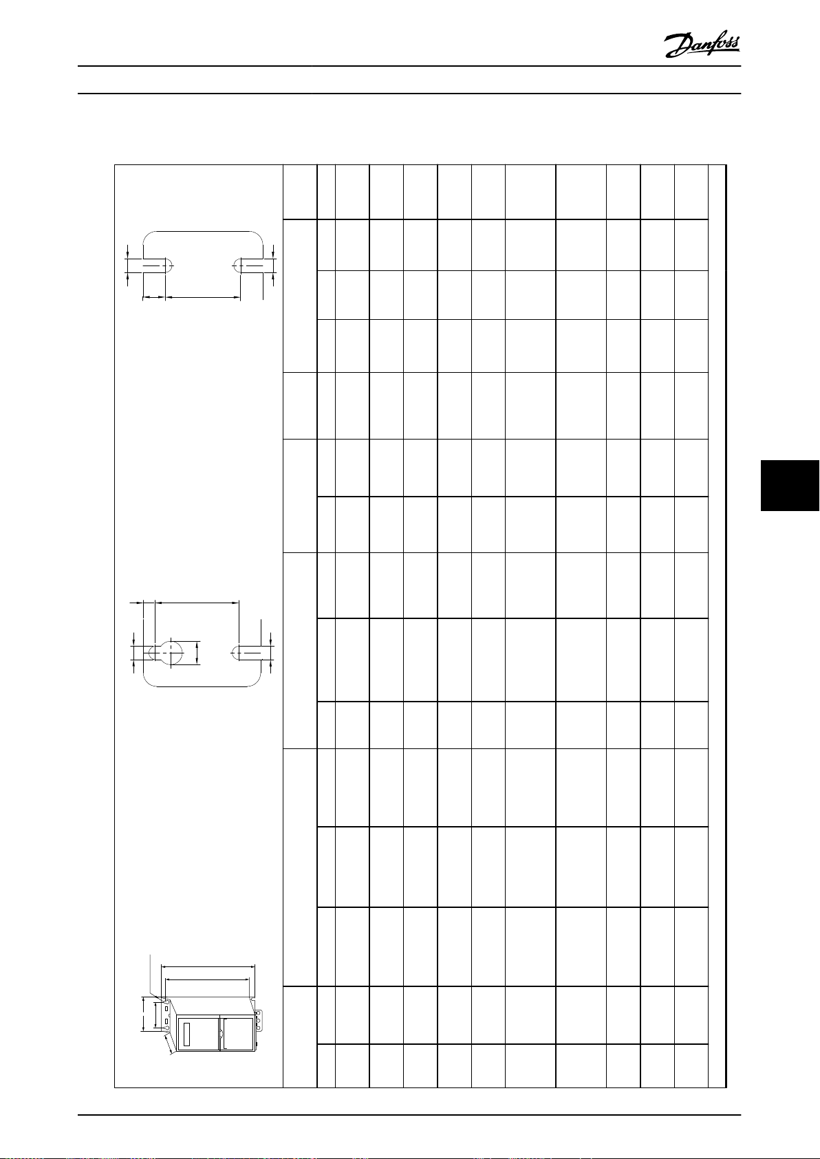
A
a
b
B
C
D
130BB614.10
e
f
a
d
e
130BC205.10
e
f
a
e
130BC246.10
一般规范 设计指南
8.1.2 变频器尺寸
2.1
5.3
4.5
3.4
(4.6)
7.4
(0.21)
5.5
(0.18)
4.5
(7.5)
8.1
(0.29)
5.5
(0.22)
7.9
(9.9)
8.4
(0.32)
7
(0.22)
9.5
(17.4)
8.5
(0.33)
7
(0.28)
(20.9)
(0.33)
(0.28)
24.5
15
8.5
(54)
(0.6)
(0.33)
17
8.5
36 (79)
(0.67)
(0.33)
51 (112)
17
8.5
6.6
9
(0.67)
5.5
(0.33)
12
(14.6)
7.5
(0.35)
6.8
(0.22)
(26.5)
(0.30)
(0.27)
安装孔 [mm (in)] 最大重量
深度
[mm (in)]
a B b C d e f kg (lb)
1)
A
273 (10.7) 183 (7.2) 75 (3.0) 56 (2.2) 168 (6.6) 9 (0.35)
195
(7.7)
11
303 (11.9) 212 (8.3) 90 (3.5) 65 (2.6) 190 (7.5)
227
11
(0.43)
100
255
(8.9)
(0.43)
74 (2.9) 206 (8.1)
(3.9)
329 (13.0) 240 (9.4)
(10.0)
12.6
105 (4.1) 241 (9.5)
135
359 (14.1) 275 (10.8)
296
12.6
(0.50)
150
(5.3)
334
(11.7)
(0.50)
120 (4.7) 255 (10)
(5.9)
402 (15.8) 314 (12.4)
(13.1)
200 (7.9) 242 (9.5) –
239
(9.4)
495 (19.5)
595
(23.4)/635
518
(20.4)
(25), 45 kW
335 (13.2) –
270
(10.6)
313
(12.3)
521 (20.5)
630
(24.8)/690
550
(21.7)
11
12
(0.43)
(0.47)
330 (13) 335 (13.2) –
110 (4.3) 205 (8.0)
140 (5.5) 248 (9.8)
375
130
165
(5.1)
399
(10.6)
(6.5)
419 (16.5) 380 (15)
(15.7)
(14.8)
800 (31.5) 631 (24.8)
(26)
374 (14.7) 257 (10.1)
269
(27.2), 75 kW
660
8 8
–
–
–
–
–
(25–40)
(40–60)
(20–25)
37–55
55–75
22–30
18.5–30
5.5–7.5
(7.5–10)
H3 IP20 3.7 (5.0)
11–15
(15–20)
5.5–7.5
(7.5–10)
H4 IP20
18.5–22
2.2–4.0
0.37–1.5
(0.5–2.0)
(3.0–5.0)
0.25–1.5
(0.33–2.0)
MG18C841 Danfoss A/S © 04/2018 全权所有。 95
机箱 功率 [kW (hp)] 高度 [mm (in)] 宽度 [mm(in)]
规格 IP 等级 3x200–240 V 3x380–480 V 3x525–600 V A
H1 IP20
H2 IP20 2.2 (3.0)
(25–30)
H5 IP20 11 (15)
30–45
15–18.5
H6 IP20
(50–70)
(70–100)
(30–40)
H7 IP20
75–90
(100–125)
90 (125)
37–45
(50–60)
H8 IP20
11–15
2.2–7.5
(3.0–10)
H9 IP20 – –
(15–20)
H10 IP20 – –
1) 包括去耦板
Page 98

A
a
b
B
C
D
130BB614.10
e
f
a
d
e
130BC205.10
e
f
a
e
130BC246.10
一般规范
VLT® HVAC Basic Drive FC 101
安装孔 [mm (in)] 最大重量
深度
[mm (in)]
88
a B b C d e f kg (lb)
1)
A
中列出了自由通风通道所需的空间量。
表 8.1
机箱 功率 [kW (hp)] 高度 [mm (in)] 宽度 [mm(in)]
96 Danfoss A/S © 04/2018 全权所有。 MG18C841
规格 IP 等级 3x200–240 V 3x380–480 V 3x525–600 V A
注意
具体安装时,请在设备上方和下方留出用于通风的空间。
上述尺寸仅为设备的物理尺寸。
表 8.2 尺寸,机箱规格 H1–H10
Page 99

A
a
b
B
C
D
130BB614.10
e
f
a
d
e
130BC205.10
e
f
a
e
130BC246.10
一般规范 设计指南
5.3
(11.7)
9 (0.35)
5.5
(0.22)
7.2
9.5
6.5
13.8
(15.9)
9.5
(0.37)
6.5
(0.26)
27
(30.42)
(0.37)
9 (0.35)
9
(0.26)
45
(59.5)
9.8
9
(0.35)
65
(99.2)
9.8
(0.39)
9
(0.35)
(143.3)
(0.39)
(0.35)
安装孔 [mm (in)] 最大重量
深度
[mm (in)]
a B b C d e f kg (lb)
1)
A
11
(0.43)
115 (4.5) 74 (2.9) 225 (8.9)
318.5
(12.53)
–
12
– 354 (13.9) 135 (5.3) 89 (3.5) 237 (9.3)
12
(0.47)
(0.47)
– 460 (18.1) 180 (7.0) 133 (5.2) 290 (11.4)
19
– 624 (24.6) 242 (9.5) 210 (8.3) 260 (10.2)
19
(0.75)
272
308
(0.75)
310 (12.2)
(10.7)
(12.1)
– 648 (25.5)
19
335 (13.2)
334
370
– 739 (29.1)
(0.75)
(13.2)
8 8
(14.6)
332
368
476
650
680
770
(13.1)
(14.5)
(18.7)
(25.6)
(26.8)
(30)
中列出了自由通风通道所需的空间量。
–
–
–
–
–
–
50)
70)
5.5–7.5
11–18.5
0.75–4.0
(1.0–5.0)
MG18C841 Danfoss A/S © 04/2018 全权所有。 97
机箱 功率 [kW (hp)] 高度 [mm (in)] 宽度 [mm(in)]
规格 IP 等级 3x200–240 V 3x380–480 V 3x525–600 V A
I2 IP54 –
I3 IP54 –
(15–25)
(7.5–10)
I4 IP54 –
22–37 (30–
I6 IP54 –
45–55 (60–
I7 IP54 –
125)
75–90 (100–
I8 IP54 –
1) 包括去耦板
表 8.1
上述尺寸仅为设备的物理尺寸。
注意
具体安装时,请在设备上方和下方留出用于通风的空间。
表 8.3 尺寸,机箱规格 I2–I8
Page 100
一般规范
8.1.3 运输尺寸
75–90/
100–125
60–70
45–55/
30–50
22–37/
VLT® HVAC Basic Drive FC 101
490/
60.5
41.5
28.3
950/
(133.4)
850/
(91.5)
850/
(62.4)
37.4
33.5
33.5
490/
410/
370/
19.3
16.1
15.6
540/
460/
19.3
21.3
18.1
11–
18.5/
15–25
11–
18.5/
15–25
7.5/
5.5–
7.5–10
88
– – – – – – – – –
50–60
37–45/
30–40
22–30/
4.0/
0.75–
90/
55–75/
1.0–
– –
125
75–100
5.0
– – – – – – –
11–15/
7.5/
2.2–
75–90/
37–55/
15–20
100–125
50–75
3–10
23.3
13.8
7.8
6.1
11.5
6.6
51
36
(51.4)
(30.4)
(17.2)
(13.4)
(25.4)
(14.6)
(112.4)
(79.4)
850/
390/
325/
310/
500/
380/
850/
850/
33.5
15.4
12.8
12.2
19.7
15.0
33.5
33.5
370/
295/
230/
205/
330/
290/
490/
410/
15.6
11.6
9.1
8.1
13.0
11.4
19.3
16.1
460/
635/
480/
435/
350/
200/
490/
540/
18.1
25.0
18.9
17.1
13.8
7.9
19.3
21.3
15–
18.5/
20–25
11/15
7.5/
5.5–
7.5–10
2.2/3 3.7/5
H1 H2 H3 H4 H5 H6 H7 H8 H9 H10 I2 I3 I4 I5 I6 I7 I8
机架机架规格
98 Danfoss A/S © 04/2018 全权所有。 MG18C841
1.5/
0.25–
V AC)
主电源电压
T2 (200–240
0.33–2
[kW/hp]
30–45/
22/
18.5–
11–15/
7.5/
5.5–
4/
2.2–
1.5/
0.37–
V AC)
T4 (380–480
40–60
25–30
15–20
7.5–
3–5.5
0.5–2
[kW/hp]
18.5–
10
T6 (525–600
30/
– – – – –
V AC)
25–40
[kW/hp]
IP 机架 IP20 IP54
24.5
9.5
7.9
4.5
3.4
2.1
最大重量 [kg
850/
(54.0)
395/
(20.9)
380/
(17.4)
280/
(9.9)
300/
(7.5)
265/
(4.6)
(lb)]
370/
33.5
15.6
233/
15.0
200/
11.0
155/
11.8
265/
10.4
230/
高度 [mm/in]
15.6
460/
9.2
380/
7.9
315/
6.1
320/
155/
10.4
9.1
135/
宽度 [mm/in]
18.1
15.0
12.4
12.6
6.1
5.3
表 8.4 尺寸
深度 [mm/in]
 Loading...