

Page 1
ENGINEERING TOMORROW
Programming Guide
VLT® HVAC Basic Drive FC 101
www.DanfossDrives.com
Page 2

Page 3

Contents Programming Guide
Contents
1 Introduction
1.1 Purpose of the Manual
1.2 Document and Software Version
1.3 Safety Symbols
1.4 Safety Precautions
1.5 Additional Resources
1.6 Denitions
1.7 Electrical Overview
2 Programming
2.1 Introduction
2.2 Local Control Panel (LCP)
2.3 Menus
2.3.1 Status Menu 10
2.3.2 Quick Menu 10
2.3.3 Main Menu 25
2.4 Quick Transfer of Parameter Settings between Multiple Frequency Converters
2.5 Readout and Programming of Indexed Parameters
3
3
3
3
4
5
5
8
9
9
9
10
25
25
2.6 Initialization to Default Settings
3 Parameters
3.1 Main Menu - Operation and Display - Group 0
3.2 Main Menu - Load and Motor - Group 1
3.3 Main Menu - Brakes - Group 2
3.4 Main Menu–Reference/Ramps–Group 3
3.5 Main Menu - Limits/Warnings - Group 4
3.6 Main Menu - Digital In/Out - Group 5
3.7 Main Menu - Analog In/Out - Group 6
3.8 Main Menu - Communications and Options - Group 8
3.9 Main Menu - Smart Logic - Group 13
3.10 Main Menu - Special Functions - Group 14
3.11 Main Menu - Drive Information - Group 15
3.12 Main Menu - Data Readouts - Group 16
3.13 Main Menu - Data Readouts 2 - Group 18
3.14 Main Menu - FC Closed Loop - Group 20
3.15 Main Menu - Application Functions - Group 22
25
27
27
32
42
44
47
50
58
64
70
78
83
84
88
89
93
3.16 Main Menu - Application Functions 2 - Group 24
3.17 Main Menu - Special Features - Group 30
MG18B522 Danfoss A/S © 05/2018 All rights reserved.
100
102
Page 4

Contents
VLT® HVAC Basic Drive FC 101
4 Troubleshooting
4.1 Introduction to Alarms and Warnings
4.2 Alarm Words
4.3 Warning Words
4.4 Extended Status Words
4.5 List of Warnings and Alarms
4.6 List of LCP Errors
5 Parameter Lists
5.1 Parameter Options
5.1.1 Default Settings 111
5.1.2 0-** Operation/Display 112
5.1.3 1-** Load and Motor 112
5.1.4 2-** Brakes 114
5.1.5 3-** Reference/Ramps 114
5.1.6 4-** Limits/Warnings 115
5.1.7 5-** Digital In/Out 115
5.1.8 6-** Analog In/Out 116
103
103
106
106
107
107
110
111
111
Index
5.1.9 8-** Comm. and Options 117
5.1.10 13-** Smart Logic 118
5.1.11 14-** Special Functions 118
5.1.12 15-** Drive Information 120
5.1.13 16-** Data Readouts 121
5.1.14 18-** Info & Readouts 122
5.1.15 20-** Drive Closed Loop 122
5.1.16 22-** Appl. Functions 123
5.1.17 24-** Appl. Functions 2 124
5.1.18 30-** Special Features 124
125
Danfoss A/S © 05/2018 All rights reserved. MG18B522
Page 5
Introduction Programming Guide
1 Introduction
1 1
1.1 Purpose of the Manual
This programming guide provides information for
advanced programming of the frequency converter. It
provides a complete overview of all parameters and
descriptions for all parameters.
The programming guide is intended for use by
qualied
personnel.
To operate the frequency converter safely and professionally, read and follow the programming guide, and pay
particular attention to the safety instructions and general
warnings.
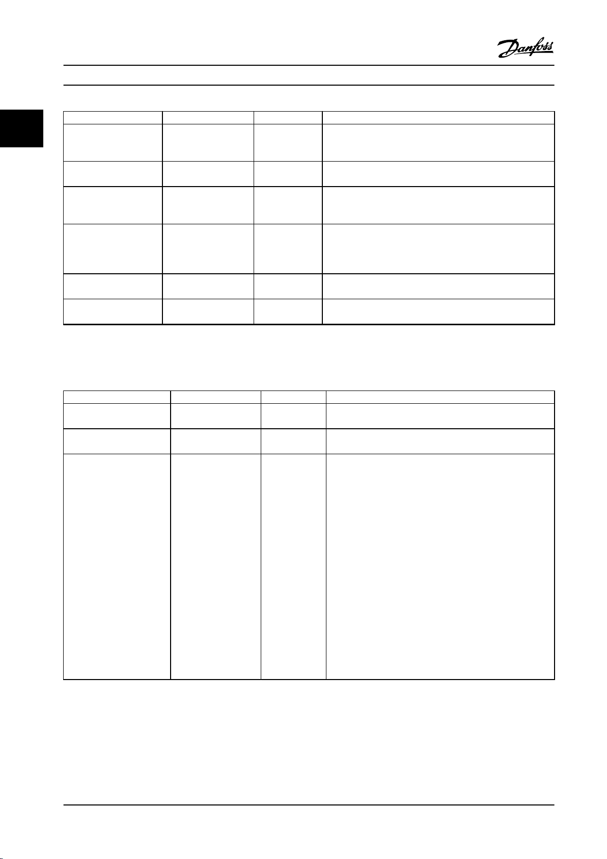
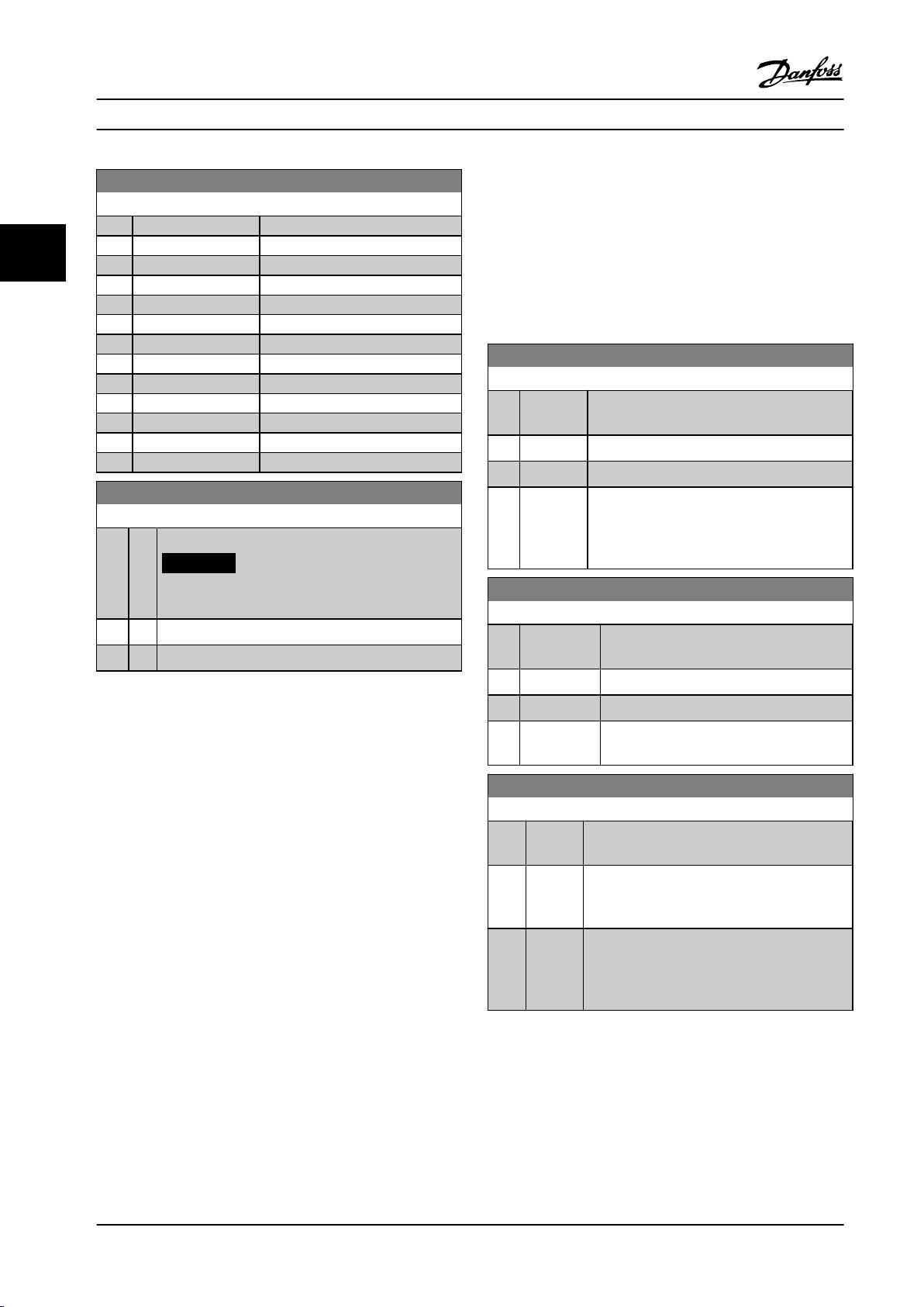
1.2 Document and Software Version
This manual is regularly reviewed and updated. All
suggestions for improvement are welcome.
Edition Remarks Software version
MG18B5xx Update to new
software version.
Table 1.1 Document and Software Version
From software version 4.0x and later (production week 33
2017 and after), the variable speed heat sink cooling fan
function is implemented in the frequency converter for
power sizes 22 kW (30 hp) 400 V IP20 and below, and 18.5
kW (25 hp) 400 V IP54 and below. This function requires
software and hardware updates and introduces restrictions
with regards to backwards compatibility for H1–H5 and I2–
I4 enclosure sizes. Refer to Table 1.2 for the limitations.
4.2x
Software
compatibility
Old software
(OSS-le version 3.xx
and below)
New software
(OSS-le version 4.xx
or higher)
Hardware
compatibility
Old power card
(production week 33
2017 or before)
New power card
(production week 34
2017 or after)
Table 1.2 Software and Hardware Compatibility
Old control card
(production week
33 2017 or before)
Yes No
No Yes
Old control card
(production week
33 2017 or before)
Yes (only software
version 3.xx or
below)
Yes (MUST update
software to version
3.xx or below, the
fan continuously
runs at full speed)
New control card
(production week
34 2017 or after)
New control card
(production week
34 2017 or after)
Yes (MUST update
software to version
4.xx or higher)
Yes (only software
version 4.xx or
higher)
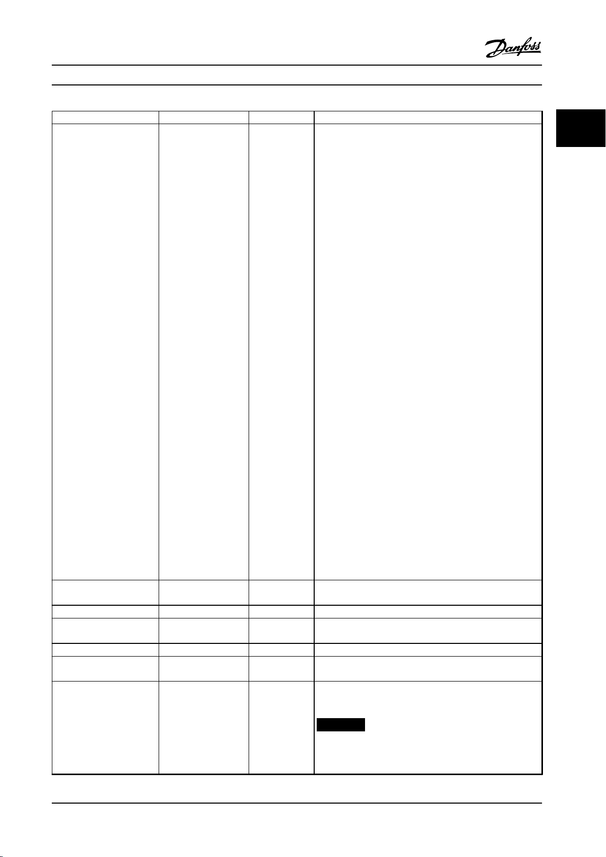
1.3 Safety Symbols
The following symbols are used in this guide:
WARNING
Indicates a potentially hazardous situation that could
result in death or serious injury.
CAUTION
Indicates a potentially hazardous situation that could
result in minor or moderate injury. It can also be used to
alert against unsafe practices.
NOTICE!
Indicates important information, including situations that
can result in damage to equipment or property.
MG18B522 Danfoss A/S © 05/2018 All rights reserved. 3
Page 6
Introduction
VLT® HVAC Basic Drive FC 101
11
1.4 Safety Precautions
WARNING
HIGH VOLTAGE
Frequency converters contain high voltage when
connected to AC mains input, DC supply, or load sharing.
Failure to perform installation, start-up, and maintenance
by qualied personnel can result in death or serious
injury.
Only qualied personnel must perform instal-
•
lation, start-up, and maintenance.
Before performing any service or repair work,
•
use an appropriate voltage measuring device to
make sure that there is no remaining voltage on
the frequency converter.
WARNING
UNINTENDED START
When the drive is connected to AC mains, DC supply, or
load sharing, the motor can start at any time.
Unintended start during programming, service, or repair
work can result in death, serious injury, or property
damage. The motor can start with an external switch, a
eldbus command, an input reference signal from the
LCP or LOP, via remote operation using MCT 10 Setup
Software, or after a cleared fault condition.
To prevent unintended motor start:
Press [O/Reset] on the LCP before
•
programming parameters.
Disconnect the drive from the mains.
•
Completely wire and assemble the drive, motor,
•
and any driven equipment before connecting
the drive to AC mains, DC supply, or load
sharing.
WARNING
DISCHARGE TIME
The frequency converter contains DC-link capacitors,
which can remain charged even when the frequency
converter is not powered. High voltage can be present
even when the warning LED indicator lights are o.
Failure to wait the specied time after power has been
removed before performing service or repair work can
result in death or serious injury.
Stop the motor.
•
Disconnect AC mains and remote DC-link power
•
supplies, including battery back-ups, UPS, and
DC-link connections to other frequency
converters.
Disconnect or lock PM motor.
•
Wait for the capacitors to discharge fully. The
•
minimum duration of waiting time is specied
in Table 1.3.
Before performing any service or repair work,
•
use an appropriate voltage measuring device to
make sure that the capacitors are fully
discharged.
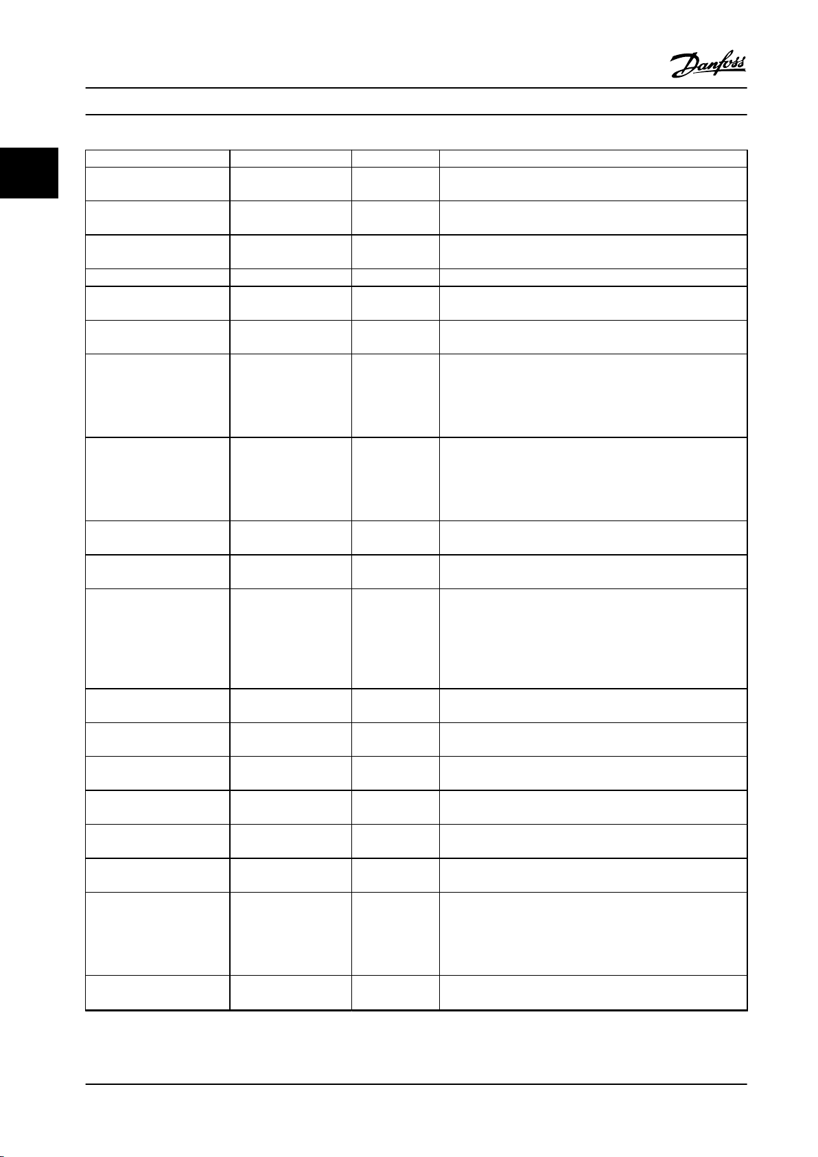
Voltage [V] Power range [kW (hp)] Minimum waiting time
(minutes)
3x200 0.25–3.7 (0.33–5) 4
3x200 5.5–11 (7–15) 15
3x400 0.37–7.5 (0.5–10) 4
3x400 11–90 (15–125) 15
3x600 2.2–7.5 (3–10) 4
3x600 11–90 (15–125) 15
Table 1.3 Discharge Time
WARNING
LEAKAGE CURRENT HAZARD
Leakage currents exceed 3.5 mA. Failure to ground the
frequency converter properly can result in death or
serious injury.
Ensure the correct grounding of the equipment
•
by a certied electrical installer.
4 Danfoss A/S © 05/2018 All rights reserved. MG18B522
Page 7
Introduction Programming Guide
1 1
WARNING
EQUIPMENT HAZARD
Contact with rotating shafts and electrical equipment
can result in death or serious injury.
Ensure that only trained and qualied personnel
•
perform installation, start-up, and maintenance.
Ensure that electrical work conforms to national
•
and local electrical codes.
Follow the procedures in this manual.
•
CAUTION
INTERNAL FAILURE HAZARD
An internal failure in the frequency converter can result
in serious injury when the frequency converter is not
properly closed.
Ensure that all safety covers are in place and
•
securely fastened before applying power.
1.5 Additional Resources
VLT® HVAC Basic Drive FC 101 Quick Guide provides
•
basic information on mechanical dimensions,
installation, and programming.
®
VLT
•
•
The technical documentation is available in electronic form
online at drives.danfoss.com/knowledge-center/technical-
documentation/.
MCT 10 Setup Software support
Download the software from www.danfoss.com/en/serviceand-support/downloads/dds/vlt-motion-control-tool-mct-10/.
During the installation process of the software, enter
access code 81463800 to activate the FC 101 functionality.
A license key is not required for using the FC 101
functionality.
HVAC Basic Drive FC 101 Design Guide
provides information on how to design motor
control systems.
Danfoss VLT® Energy Box software. Select PC
Software Download at vlt-drives.danfoss.com/
products/engineering-software/software-download/
vlt-energy-box-software/.
VLT®Energy Box software allows energy
consumption comparisons of HVAC fans and
pumps driven by Danfoss frequency converters
and alternative methods of ow control. Use this
tool to project the costs, savings, and payback of
using Danfoss frequency converters on HVAC
fans, pumps, and cooling towers.
The latest software does not always contain the latest
updates for frequency converters. Contact the local sales
oce for the latest frequency converter updates (in the
form of *.upd les), or download the frequency converter
updates from www.danfoss.com/en/service-and-support/
downloads/dds/vlt-motion-control-tool-mct-10/#Overview.
1.6 Denitions
Frequency converter
I
VLT, MAX
The maximum output current.
I
VLT,N
The rated output current supplied by the frequency
converter.
U
VLT, MAX
The maximum output voltage.
Input
The connected motor can start and stop via LCP and
digital inputs. Functions are divided into 2 groups, as
described in Table 1.4. Functions in group 1 have higher
priority than functions in group 2.
Group 1
Group 2
Table 1.4 Control Commands
Motor
f
JOG
The motor frequency when the jog function is activated
(via digital terminals).
f
M
The motor frequency.
f
MAX
The maximum motor frequency.
f
MIN
The minimum motor frequency.
f
M,N
The rated motor frequency (nameplate data).
I
M
The motor current.
I
M,N
The rated motor current (nameplate data).
n
M,N
The nominal motor speed (nameplate data).
P
M,N
The rated motor power (nameplate data).
U
M
The instantaneous motor voltage.
Reset, coast stop, reset and coast stop, quick
stop, DC brake, stop, and [O].
Start, pulse start, reversing, start reversing, jog,
and freeze output.
MG18B522 Danfoss A/S © 05/2018 All rights reserved. 5
Page 8
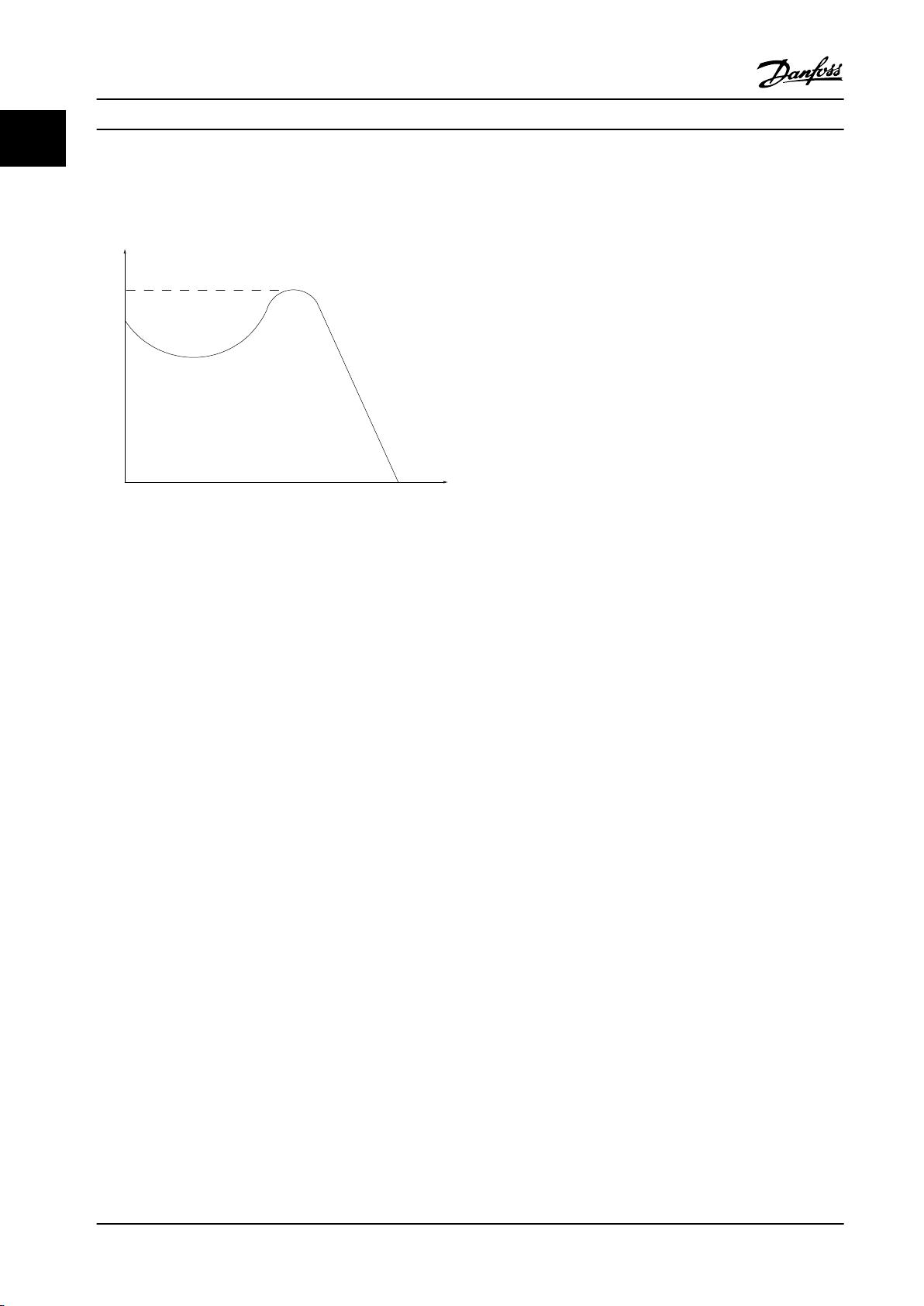
175ZA078.10
Pull-out
RPM
Torque
Introduction
VLT® HVAC Basic Drive FC 101
11
U
M,N
The rated motor voltage (nameplate data).
Break-away torque
Figure 1.1 Break-away Torque
η
VLT
The eciency of the frequency converter is dened as the
ratio between the power output and the power input.
Start-disable command
A stop command belonging to the group 1 control
commands, see Table 1.4.
Stop command
See Table 1.4.
Analog reference
A signal transmitted to the analog inputs 53 or 54. It can
be voltage or current.
Current input: 0–20 mA and 4–20 mA
•
Voltage input: 0–10 V DC
•
Bus reference
A signal transmitted to the serial communication port (FC
port).
Preset reference
A dened preset reference to be set from -100% to +100%
of the reference range. Selection of 8 preset references via
the digital terminals.
Ref
MAX
Determines the relationship between the reference input at
100% full scale value (typically 10 V, 20 mA) and the
resulting reference. The maximum reference value set in
parameter 3-03 Maximum Reference.
Ref
MIN
Determines the relationship between the reference input at
0% value (typically 0 V, 0 mA, 4 mA) and the resulting
reference. The minimum reference value is set in
parameter 3-02 Minimum Reference.
Analog inputs
The analog inputs are used for controlling various
functions of the frequency converter.
There are 2 types of analog inputs:
Current input: 0–20 mA and 4–20 mA
•
Voltage input: 0–10 V DC
•
Analog outputs
The analog outputs can supply a signal of 0–20 mA, 4–
20 mA, or a digital signal.
Automatic motor adaptation, AMA
The AMA algorithm determines the electrical parameters
for the connected motor at standstill and compensates for
the resistance based on the length of the motor cable.
Digital inputs
The digital inputs can be used for controlling various
functions of the frequency converter.
Digital outputs
The frequency converter provides 2 solid-state outputs that
can supply a 24 V DC (maximum 40 mA) signal.
Relay outputs
The frequency converter provides 2 programmable relay
outputs.
ETR
Electronic thermal relay is a thermal load calculation based
on present load and time. Its purpose is to estimate the
motor temperature and prevent overheating of the motor.
Initializing
If initializing is carried out (parameter 14-22 Operation
Mode), the programmable parameters of the frequency
converter return to their default settings.
Parameter 14-22 Operation Mode does not initialize
communication parameters, fault log, or re mode log.
Intermittent duty cycle
An intermittent duty rating refers to a sequence of duty
cycles. Each cycle consists of an on-load and an o-load
period. The operation can be either periodic duty or noneperiodic duty.
LCP
The local control panel (LCP) makes up a complete
interface for control and programming of the frequency
converter. The control panel is detachable on IP20 units
and xed on IP54 units. It can be installed up to 3 m
(9.8 ft) from the frequency converter, that is, in a front
panel with the installation kit option.
Lsb
Least signicant bit.
MCM
Short for mille circular mil, an American measuring unit for
cable cross-section. 1 MCM = 0.5067 mm2.
6 Danfoss A/S © 05/2018 All rights reserved. MG18B522
Page 9

Introduction Programming Guide
1 1
Msb
Most signicant bit.
On-line/O-line parameters
Changes to on-line parameters are activated immediately
after the data value is changed. Press [OK] to activate o-
line parameters.
PI controller
The PI controller maintains the desired speed, pressure,
temperature, and so on, by adjusting the output frequency
to match the varying load.
RCD
Residual current device.
Set-up
Parameter settings in 2 set-ups can be saved. Change
between the 2 parameter set-ups and edit 1 set-up, while
another set-up is active.
Slip compensation
The frequency converter compensates for the motor slip by
giving the frequency a supplement that follows the
measured motor load keeping the motor speed almost
constant.
Smart logic control (SLC)
The SLC is a sequence of user-dened actions executed
when the associated user-dened events are evaluated as
true by the SLC.
Thermistor
A temperature-dependent resistor placed where the
temperature is to be monitored (frequency converter or
motor).
Trip
A state entered in fault situations, for example, if the
frequency converter is subject to an overtemperature or
when the frequency converter is protecting the motor,
process, or mechanism. Restart is prevented until the cause
of the fault does not exist and the trip state is canceled by
activating reset or, sometimes, by being programmed to
reset automatically. Do not use trip for personal safety.
Trip lock
A state entered in fault situations when the frequency
converter is protecting itself and requiring physical
intervention, for example, if the frequency converter is
subject to a short circuit on the output. A locked trip can
only be canceled by cutting o mains, removing the cause
of the fault, and reconnecting the frequency converter.
Restart is prevented until the trip state is canceled by
activating reset or, sometimes, by being programmed to
reset automatically. Do not use trip lock for personal safety.
VT characteristics
Variable torque characteristics used for pumps and fans.
+
VVC
If compared with standard voltage/frequency ratio control,
voltage vector control (VVC+) improves the dynamics and
the stability, both when the speed reference is changed
and in relation to the load torque.
MG18B522 Danfoss A/S © 05/2018 All rights reserved. 7
Page 10
L1
L2
L3
3-phase
power
input
PE
PE
+10 V DC
0-10 V DC-
0-10 V DC-
50 (+10 V OUT)
54 (A IN)
53 (A IN)
55 (COM A IN/OUT)
0/4-20 mA
0/4-20 mA
42 0/4-20 mA A OUT / D OUT
45 0/4-20 mA A OUT / D OUT
18 (D IN)
19 (D IN)
27 (D IN/OUT)
29 (D IN/OUT)
12 (+24 V OUT)
24 V (NPN)
20 (COM D IN)
O V (PNP)
24 V (NPN)
O V (PNP)
24 V (NPN)
O V (PNP)
24 V (NPN)
O V (PNP)
Bus ter.
Bus ter.
RS485
Interface
RS485
(N RS485) 69
(P RS485) 68
(Com RS485 ) 61
(PNP)-Source
(NPN)-Sink
ON=Terminated
OFF=Unterminated
ON
1 2
240 V AC 3 A
Not present on all power sizes
Do not connect shield to 61
01
02
03
relay 1
relay 2
UDC+
UDC-
Motor
U
V
W
130BD467.12
06
05
04
240 V AC 3 A
Introduction
VLT® HVAC Basic Drive FC 101
11
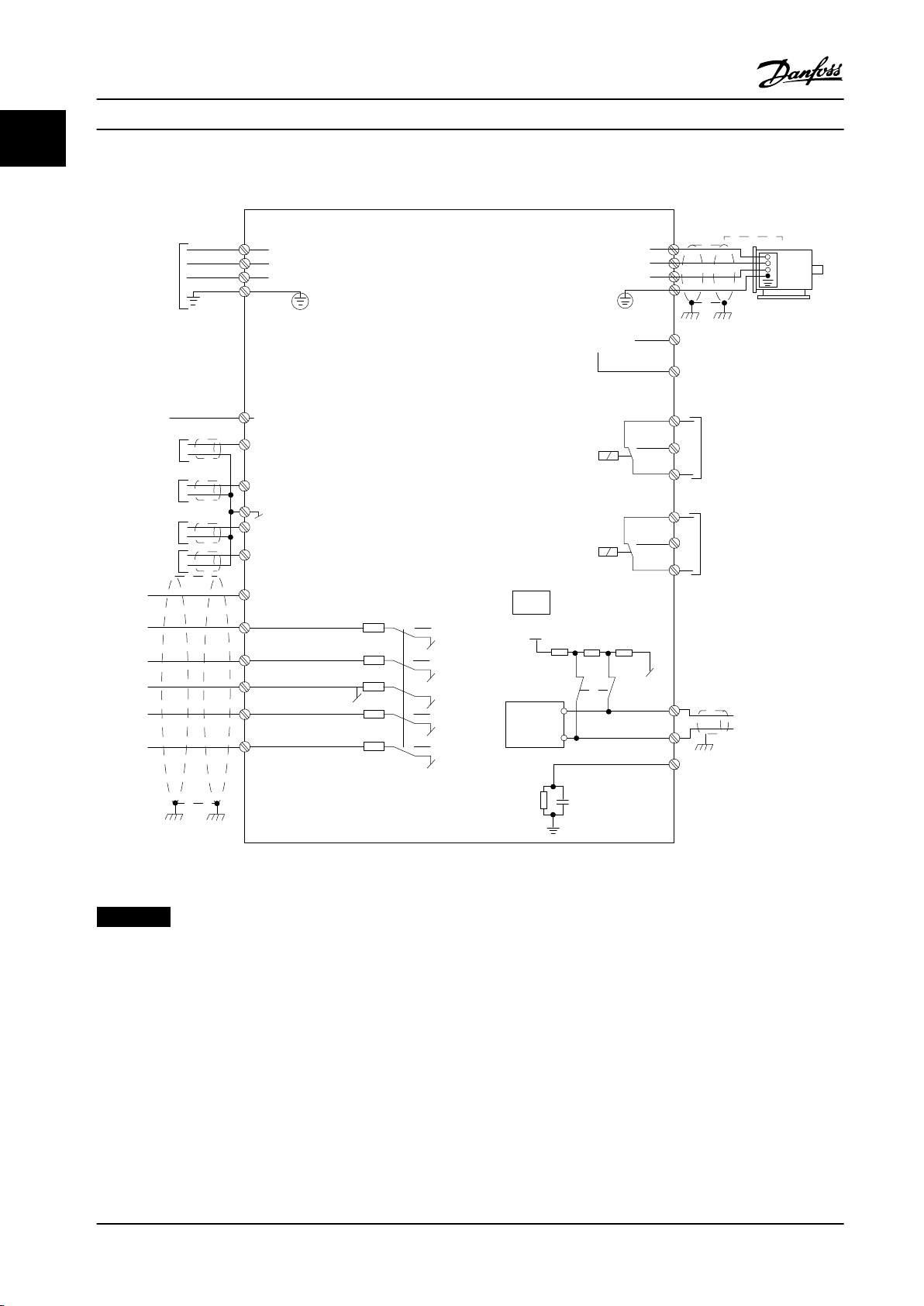
1.7 Electrical Overview
Figure 1.2 Basic Wiring Schematic Drawing
NOTICE!
There is no access to UDC- and UDC+ on the following units:
8 Danfoss A/S © 05/2018 All rights reserved. MG18B522
IP20, 380–480 V, 30–90 kW (40–125 hp)
•
•
•
•
IP20, 200–240 V, 15–45 kW (20–60 hp)
IP20, 525–600 V, 2.2–90 kW (3.0–125 hp)
IP54, 380–480 V, 22–90 kW (30–125 hp)
Page 11
B
a
c
k
Com.
1-20 Motor Power
[5] 0.37kW - 0.5HP
Setup 1
AB1
12
131415
11
11
109876
5
432
C
D
Sta
tus
M
ain
M
enu
Q
uick
M
enu
Hand
On
OK
M
enu
Off
Reset
Auto
On
Alarm
Warn.
On
11
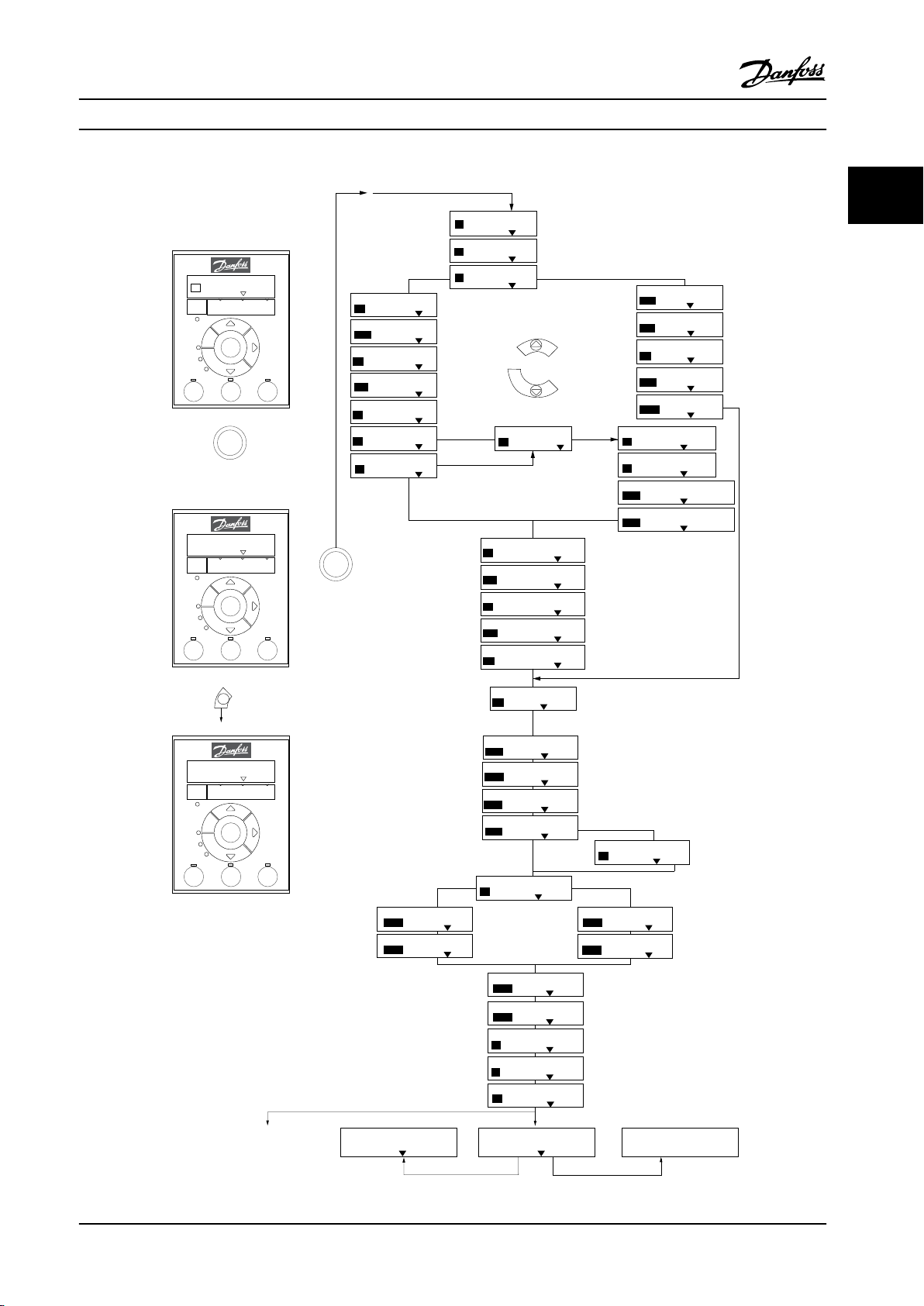
Programming Programming Guide
2 Programming
2.1 Introduction
The frequency converter can be programmed from the LCP
or from a PC via the RS485 COM port by installing the MCT
10 Setup Software. Refer to chapter 1.5 Additional Resources
for more details about the software.
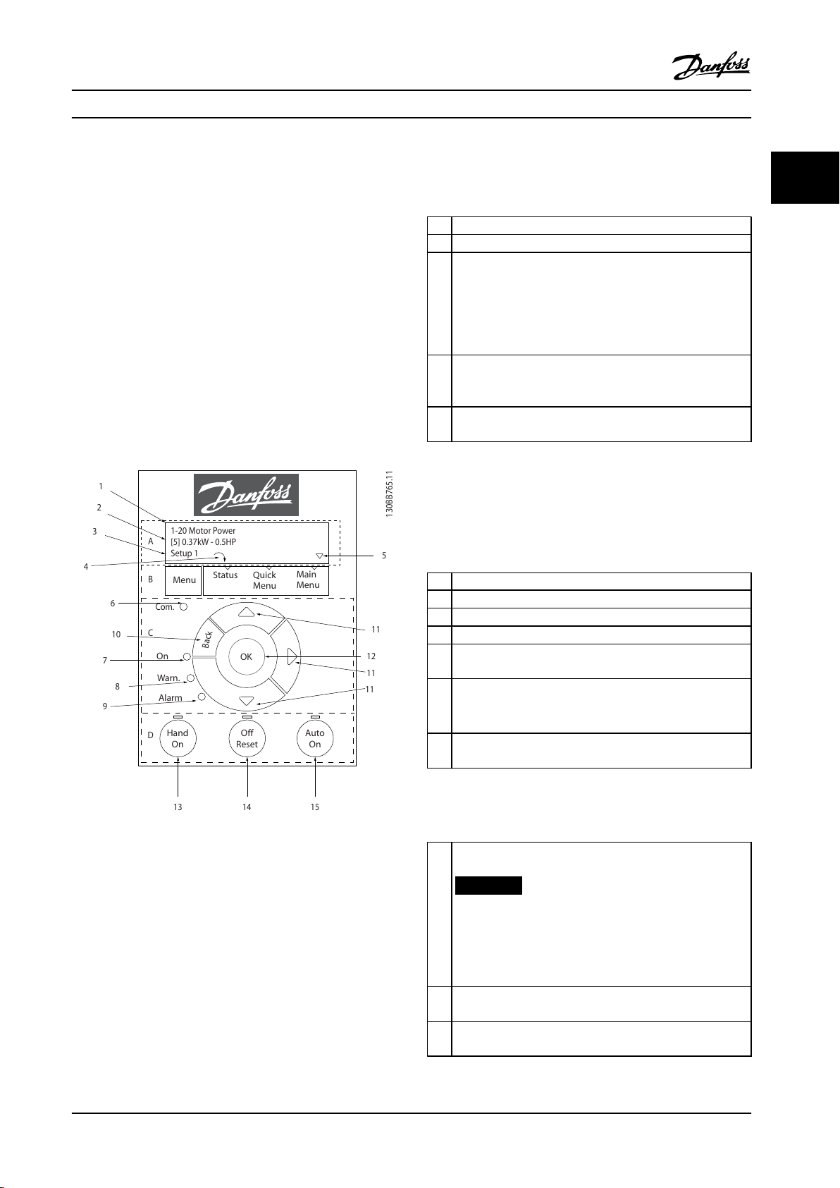
2.2 Local Control Panel (LCP)
The LCP is divided into 4 functional sections.
A. Display
B. Menu key
C. Navigation keys and indicator lights
D. Operation keys and indicator lights
1 Parameter number and name.
2 Parameter value.
Set-up number shows the active set-up and the edit set-up.
If the same set-up acts as both active and edit set-up, only
that set-up number is shown (factory setting). When active
3
and edit set-up dier, both numbers are shown in the
display (set-up 12). The number ashing indicates the edit
set-up.
Motor direction is shown to the bottom left of the display –
4
indicated by a small arrow pointing either clockwise or
counterclockwise.
The triangle indicates if the LCP is in Status, Quick Menu, or
5
Main Menu.
Table 2.1 Legend to Figure 2.1, Part I
B. Menu key
Press [Menu] to select among Status, Quick Menu, or Main
Menu.
C. Navigation keys and indicator lights
2 2
Figure 2.1 Local Control Panel (LCP)
A. Display
The LCD display is illuminated with 2 alphanumeric lines.
All data is shown on the LCP.
Figure 2.1 describes the information that can be read from
the display.
6 Com. LED: Flashes during bus communication.
7 Green LED/On: Control section is working correctly.
8 Yellow LED/Warn.: Indicates a warning.
9 Flashing Red LED/Alarm: Indicates an alarm.
[Back]: For moving to the previous step or layer in the
10
navigation structure.
[▲] [▼] [►]: For navigating among parameter groups and
11
parameters, and within parameters. They can also be used
for setting local reference.
[OK]: For selecting a parameter and for accepting changes
12
to parameter settings.
Table 2.2 Legend to Figure 2.1, Part II
D. Operation keys and indicator lights
[Hand On]: Starts the motor and enables control of the
frequency converter via the LCP.
NOTICE!
[2] Coast inverse is the default option for
13
parameter 5-12 Terminal 27 Digital Input. If there is
no 24 V supply to terminal 27, [Hand On] does not
start the motor. Connect terminal 12 to terminal 27.
[O/Reset]: Stops the motor (O). If in alarm mode, the
14
alarm is reset.
[Auto On]: The frequency converter is controlled either via
15
control terminals or serial communication.
Table 2.3 Legend to Figure 2.1, Part III
MG18B522 Danfoss A/S © 05/2018 All rights reserved. 9
Page 12
FC
+24V
DIG IN
DIG IN
DIG IN
DIG IN
COM DIG IN
A OUT / D OUT
A OUT / D OUT
18
19
27
29
42
55
50
53
54
20
12
01
02
03
04
05
06
R2
R1
0-10 V
Reference
Start
+10V
A IN
A IN
COM
130BB674.10
45
+
-
130BB629.10
Press OK to start Wizard
Push Back to skip it
Set-up 1
Programming
VLT® HVAC Basic Drive FC 101
2.3 Menus
22
2.3.1 Status Menu
The wizard is shown after power-up until any parameter
has been changed. The wizard can always be accessed
again through the quick menu. Press [OK] to start the
wizard. Press [Back] to return to the status view.
In the Status menu, the selection options are:
Motor frequency [Hz], parameter 16-13 Frequency.
•
Motor current [A], parameter 16-14 Motor current.
•
Motor speed reference in percentage [%],
•
parameter 16-02 Reference [%].
Feedback, parameter 16-52 Feedback[Unit].
•
Motor power, parameter 16-10 Power [kW] for kW,
•
Figure 2.3 Start-up/Quit Wizard
parameter 16-11 Power [hp] for hp. If
parameter 0-03 Regional Settings is set to [1] North
America, motor power is shown in hp instead of
kW.
Custom readout, parameter 16-09 Custom Readout.
•
Motor Speed [RPM], parameter 16-17 Speed [RPM].
•
2.3.2 Quick Menu
Use the Quick Menu to program the most common
functions. The Quick Menu consists of:
Wizard for open loop applications. See Figure 2.4
•
for details.
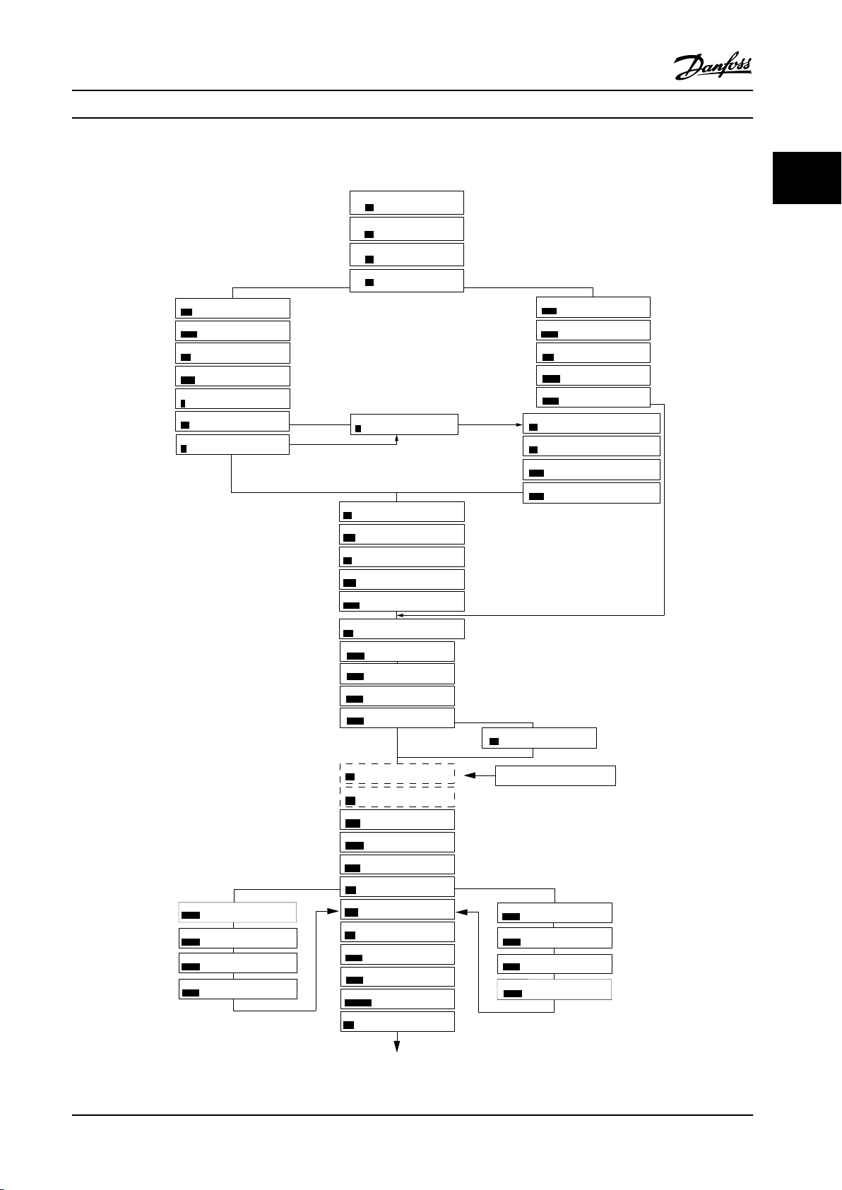
Wizard for closed loop applications. See Figure 2.5
•
for details.
Motor set-up. See Table 2.6 for details.
•
Changes made.
•
The built-in wizard menu guides the installer through the
set-up of the frequency converter in a clear and structured
manner for open-loop applications, closed-loop
applications, and quick motor settings.
Figure 2.2 Frequency Converter Wiring
10 Danfoss A/S © 05/2018 All rights reserved. MG18B522
Page 13
Power kW/50 Hz
OK
Motor Power
Motor Voltage
Motor Frequency
Motor Current
Motor nominal speed
if
Select Regional Settings
... the Wizard starts
200-240V/50Hz/Delta
Grid Type
Asynchronous motor
Asynchronous
Motor Type
Motor current
Motor nominal speed
Motor Cont. Rated Torque
Stator resistance
Motor poles
Back EMF at 1000 rpm
Motor type = IPM
Motor type = SPM
d-axis Inductance Sat. (LdSat)
[0]
[0]
3.8
A
3000
RPM
5.4
Nm
0.65
Ohms
8
Start Mode
Rotor Detection
[0]
Position Detection Gain
%
Off
100
Locked Rotor Detection
[0]
s
Locked Rotor Detection Time[s]
0.10
57
V
5
mH
q-axis Inductance (Lq)
5
mH
1.10
kW
400
V
50
Hz
Max Output Frequency
65
Hz
Motor Cable Length
50
m
4.66
A
1420
RPM
[0]
PM motor
Set Motor Speed low Limit
Hz
Set Motor Speed high Limit
Hz
Set Ramp 1 ramp-up time
s
Set Ramp 1 ramp-down Time
s
Active Flying start?
Disable
Set T53 low Voltage
V
Set T53 high Voltage
V
Set T53 Low Current
A
Set T53 High Current
A
Voltage
AMA Failed
AMA Failed
Automatic Motor Adaption
Auto Motor Adapt OK
Press OK
Select Function of Relay 2
No function
Off
Select Function of Relay 1
[0] No function
Set Max Reference
Hz
Hz
Set Min Reference
AMA running
-----
Do AMA
(Do not AMA)
AMA OK
[0]
[0]
[0]
Select T53 Mode
Current
Current
Motor type = Asynchronous
Motor type = PM motor
0000
0050
0010
0010
[0]
[0]
04.66
13.30
0050
0220
0000
0050
B
a
c
k
Status Screen
The Wizard can always be
reentered via the Quick Menu
At power-up, select the
preferred language.
The next screen is
the Wizard screen.
Wizard Screen
if
OK
Power-up Screen
Status
Main
Menu
Quick
Menu
Hand
On
OK
Menu
Reset
Off
Auto
On
Alarm
Warn.
On
Select language
[1] English
Setup 1
B
a
c
k
Com.
Status
Main
Menu
Quick
Menu
Hand
On
OK
Menu
Reset
Off
Auto
On
Alarm
Warn.
On
Press OK to start Wizard
Press Back to skip it
Setup 1
B
a
c
k
Com.
Status
Main
Menu
Quick
Menu
Hand
On
OK
Menu
Reset
Off
Auto
On
Alarm
Warn.
On
0.0 Hz
0.0 kW
Setup 1
B
a
c
k
Com.
130BC244.16
q-axis Inductance Sat. (LqSat)
5
mH
Current at Min Inductance for d-axis
100
%
Current at Min Inductance for q-axis
100
%
d-axis Inductance (Lq)
5
mH
... the Wizard starts
Programming Programming Guide
2 2
Figure 2.4 Set-up Wizard for Open-loop Applications
MG18B522 Danfoss A/S © 05/2018 All rights reserved. 11
Page 14

Programming
VLT® HVAC Basic Drive FC 101
Set-up Wizard for Open-loop Applications
22
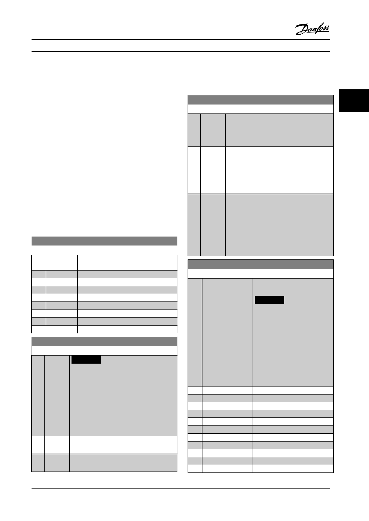
Parameter Option Default Usage
Parameter 0-03 Regional
Settings
[0] International
[1] US
[0] International –
Parameter 0-06 GridType [0] 200–240 V/50 Hz/IT-
grid
[1] 200–240 V/50 Hz/
Delta
[2] 200–240 V/50 Hz
[10] 380–440 V/50 Hz/IT-
grid
[11] 380–440 V/50 Hz/
Delta
[12] 380–440 V/50 Hz
[20] 440–480 V/50 Hz/IT-
grid
[21] 440–480 V/50 Hz/
Delta
[22] 440–480 V/50 Hz
[30] 525–600 V/50 Hz/IT-
grid
[31] 525–600 V/50 Hz/
Delta
[32] 525–600 V/50 Hz
[100] 200–240 V/60
Hz/IT-grid
[101] 200–240 V/60 Hz/
Delta
[102] 200–240 V/60 Hz
[110] 380–440 V/60
Hz/IT-grid
[111] 380–440 V/60 Hz/
Delta
[112] 380–440 V/60 Hz
[120] 440–480 V/60
Hz/IT-grid
[121] 440–480 V/60 Hz/
Delta
[122] 440–480 V/60 Hz
[130] 525–600 V/60
Hz/IT-grid
[131] 525–600 V/60 Hz/
Delta
[132] 525–600 V/60 Hz
Size related Select the operating mode for restart after reconnection of the
frequency converter to mains voltage after power-down.
12 Danfoss A/S © 05/2018 All rights reserved. MG18B522
Page 15

Programming Programming Guide
Parameter Option Default Usage
Parameter 1-10 Motor
Construction
*[0] Asynchron
[1] PM, non-salient SPM
[3] PM, salient IPM
[0] Asynchron Setting the parameter value might change these parameters:
•
•
•
•
•
•
•
•
•
•
•
•
•
•
•
•
•
•
•
•
•
•
•
•
•
•
•
•
•
•
•
•
•
•
•
•
•
•
2 2
Parameter 1-01 Motor Control Principle.
Parameter 1-03 Torque Characteristics.
Parameter 1-08 Motor Control Bandwidth.
Parameter 1-14 Damping Gain.
Parameter 1-15 Low Speed Filter Time Const.
Parameter 1-16 High Speed Filter Time Const.
Parameter 1-17 Voltage lter time const.
Parameter 1-20 Motor Power.
Parameter 1-22 Motor Voltage.
Parameter 1-23 Motor Frequency.
Parameter 1-24 Motor Current.
Parameter 1-25 Motor Nominal Speed.
Parameter 1-26 Motor Cont. Rated Torque.
Parameter 1-30 Stator Resistance (Rs).
Parameter 1-33 Stator Leakage Reactance (X1).
Parameter 1-35 Main Reactance (Xh).
Parameter 1-37 d-axis Inductance (Ld).
Parameter 1-38 q-axis Inductance (Lq).
Parameter 1-39 Motor Poles.
Parameter 1-40 Back EMF at 1000 RPM.
Parameter 1-44 d-axis Inductance Sat. (LdSat).
Parameter 1-45 q-axis Inductance Sat. (LqSat).
Parameter 1-46 Position Detection Gain.
Parameter 1-48 Current at Min Inductance for d-axis.
Parameter 1-49 Current at Min Inductance for q-axis.
Parameter 1-66 Min. Current at Low Speed.
Parameter 1-70 Start Mode.
Parameter 1-72 Start Function.
Parameter 1-73 Flying Start.
Parameter 1-80 Function at Stop.
Parameter 1-82 Min Speed for Function at Stop [Hz].
Parameter 1-90 Motor Thermal Protection.
Parameter 2-00 DC Hold/Motor Preheat Current.
Parameter 2-01 DC Brake Current.
Parameter 2-02 DC Braking Time.
Parameter 2-04 DC Brake Cut In Speed.
Parameter 2-10 Brake Function.
Parameter 4-14 Motor Speed High Limit [Hz].
MG18B522 Danfoss A/S © 05/2018 All rights reserved. 13
Page 16
Programming
Parameter Option Default Usage
22
Parameter 1-10 Motor
Construction
Parameter 1-20 Motor
Power
Parameter 1-22 Motor
Voltage
Parameter 1-23 Motor
Frequency
Parameter 1-24 Motor
Current
Parameter 1-25 Motor
Nominal Speed
Parameter 1-26 Motor Cont.
Rated Torque
*[0] Asynchron
[1] PM, non-salient SPM
[3] PM, salient IPM
0.12–110 kW/0.16–150hpSize related Enter the motor power from the nameplate data.
50–1000 V Size related Enter the motor voltage from the nameplate data.
20–400 Hz Size related Enter the motor frequency from the nameplate data.
0.01–10000.00 A Size related Enter the motor current from the nameplate data.
50–9999 RPM Size related Enter the motor nominal speed from the nameplate data.
0.1–1000.0 Nm Size related This parameter is available when parameter 1-10 Motor
VLT® HVAC Basic Drive FC 101
[0] Asynchron
Parameter 4-19 Max Output Frequency.
•
Parameter 4-58 Missing Motor Phase Function.
•
Parameter 14-65 Speed Derate Dead Time Compensation.
•
Construction is set to options that enable permanent magnet
motor mode.
NOTICE!
Changing this parameter aects the settings of other
parameters.
Parameter 1-29 Automatic
Motor Adaption (AMA)
Parameter 1-30 Stator
Resistance (Rs)
Parameter 1-37 d-axis
Inductance (Ld)
Parameter 1-38 q-axis
Inductance (Lq)
Parameter 1-39 Motor Poles 2–100 4 Enter the number of motor poles.
Parameter 1-40 Back EMF at
1000 RPM
Parameter 1-42 Motor Cable
Length
Parameter 1-44 d-axis
Inductance Sat. (LdSat)
Parameter 1-45 q-axis
Inductance Sat. (LqSat)
Parameter 1-46 Position
Detection Gain
Parameter 1-48 Current at
Min Inductance for d-axis
See
parameter 1-29 Automat
ic Motor Adaption
(AMA).
0.000–99.990 Ω
0.000–1000.000 mH Size related Enter the value of the d-axis inductance.
0.000–1000.000 mH Size related Enter the value of the q-axis inductance.
10–9000 V Size related Line-line RMS back EMF voltage at 1000 RPM.
0–100 m 50 m Enter the motor cable length.
0.000–1000.000 mH Size related This parameter corresponds to the inductance saturation of Ld.
0.000–1000.000 mH Size related This parameter corresponds to the inductance saturation of Lq.
20–200% 100% Adjusts the height of the test pulse during position detection at
20–200% 100% Enter the inductance saturation point.
O Performing an AMA optimizes motor performance.
Size related Set the stator resistance value.
Obtain the value from the permanent magnet motor datasheet.
Ideally, this parameter has the same value as parameter 1-37 d-axis
Inductance (Ld). However, if the motor supplier provides an
induction curve, enter the induction value, which is 200% of the
nominal current.
Ideally, this parameter has the same value as parameter 1-38 q-axis
Inductance (Lq). However, if the motor supplier provides an
induction curve, enter the induction value, which is 200% of the
nominal current.
start.
14 Danfoss A/S © 05/2018 All rights reserved. MG18B522
Page 17

Programming Programming Guide
Parameter Option Default Usage
Parameter 1-49 Current at
Min Inductance for q-axis
Parameter 1-70 Start Mode [0] Rotor Detection
Parameter 1-73 Flying Start [0] Disabled
Parameter 3-02 Minimum
Reference
Parameter 3-03 Maximum
Reference
Parameter 3-41 Ramp 1
Ramp Up Time
Parameter 3-42 Ramp 1
Ramp Down Time
Parameter 4-12 Motor
Speed Low Limit [Hz]
Parameter 4-14 Motor
Speed High Limit [Hz]
Parameter 4-19 Max Output
Frequency
Parameter 5-40 Function
Relay
Parameter 5-40 Function
Relay
Parameter 6-10 Terminal 53
Low Voltage
Parameter 6-11 Terminal 53
High Voltage
Parameter 6-12 Terminal 53
Low Current
Parameter 6-13 Terminal 53
High Current
Parameter 6-19 Terminal 53
mode
Parameter 30-22 Locked
Rotor Protection
20–200% 100% This parameter species the saturation curve of the d- and q-
inductance values. From 20–100% of this parameter, the
inductances are linearly approximated due to parameter 1-37 d-axis
Inductance (Ld), parameter 1-38 q-axis Inductance (Lq),
parameter 1-44 d-axis Inductance Sat. (LdSat), and parameter 1-45 q-
axis Inductance Sat. (LqSat).
[0] Rotor
[1] Parking
[1] Enabled
-4999.000–4999.000 0 The minimum reference is the lowest value obtainable by
-4999.000–4999.000 50 The maximum reference is the highest value obtainable by
0.05–3600.00 s Size related If asynchronous motor is selected, the ramp-up time is from 0 to
0.05–3600.00 s Size related For asynchronous motors, the ramp-down time is from rated
0.0–400.0 Hz 0 Hz Enter the minimum limit for low speed.
0.0–400.0 Hz 100 Hz Enter the maximum limit for high speed.
0.0–400.0 Hz 100 Hz Enter the maximum output frequency value. If parameter 4-19 Max
See
parameter 5-40 Function
Relay.
See
parameter 5-40 Function
Relay.
0.00–10.00 V 0.07 V Enter the voltage that corresponds to the low reference value.
0.00–10.00 V 10 V Enter the voltage that corresponds to the high reference value.
0.00–20.00 mA 4 mA Enter the current that corresponds to the low reference value.
0.00–20.00 mA 20 mA Enter the current that corresponds to the high reference value.
[0] Current
[1] Voltage
[0] O
[1] On
Detection
[0] Disabled Select [1] Enabled to enable the frequency converter to catch a
[9] Alarm Select the function to control output relay 1.
[5] Drive running Select the function to control output relay 2.
[1] Voltage Select if terminal 53 is used for current or voltage input.
[0] O
Select the PM motor start mode.
motor spinning due to mains drop-out. Select [0] Disabled if this
function is not required. When this parameter is set to [1] Enabled,
parameter 1-71 Start Delay and parameter 1-72 Start Function are
not functional. Parameter 1-73 Flying Start is active in VVC+ mode
only.
summing all references.
summing all references.
rated parameter 1-23 Motor Frequency. If PM motor is selected, the
ramp-up time is from 0 to parameter 1-25 Motor Nominal Speed.
parameter 1-23 Motor Frequency to 0. For PM motors, the ramp-
down time is from parameter 1-25 Motor Nominal Speed to 0.
Output Frequency is set lower than parameter 4-14 Motor Speed
High Limit [Hz], parameter 4-14 Motor Speed High Limit [Hz] is set
equal to parameter 4-19 Max Output Frequency automatically.
–
2 2
MG18B522 Danfoss A/S © 05/2018 All rights reserved. 15
Page 18

Programming
Parameter Option Default Usage
22
Parameter 30-23 Locked
Rotor Detection Time [s]
Table 2.4 Set-up Wizard for Open-loop Applications
0.05–1 s 0.10 s
VLT® HVAC Basic Drive FC 101
–
16 Danfoss A/S © 05/2018 All rights reserved. MG18B522
Page 19
6-29 Terminal 54 Mode
[1]
Voltage
6-25 T54 high Feedback
0050
Hz
20-94 PI integral time
0020.00
s
Current
Voltage
This dialog is forced to be set to
[1] Analog input 54
20-00 Feedback 1 source
[1]
Analog input 54
3-10 Preset reference [0]
0.00
3-03 Max Reference
50.00
3-02 Min Reference
0.00
Asynchronous motor
1-73 Flying Start
[0]
No
1-22 Motor Voltage
400
V
1-24 Motor Current
04.66
A
1-25 Motor nominal speed
1420
RPM
3-41 Ramp 1 ramp-up time
0010
s
3-42 Ramp1 ramp-down time
0010
s
0-06 Grid Type
4-12 Motor speed low limit
0016
Hz
4-13 Motor speed high limit
0050
Hz
130BC402.14
1-20 Motor Power
1.10
kW
1-23 Motor Frequency
50
Hz
6-22 T54 Low Current
A
6-24 T54 low Feedback
0016
Hz
6-23 T54 high Current
13.30
A
6-25 T54 high Feedback
0050
0.01
s
20-81 PI Normal/Inverse Control
[0]
Normal
20-83 PI Normal/Inverse Control
0050
Hz
20-93 PI Proportional Gain
00.50
1-29 Automatic Motor Adaption
[0]
Off
6-20 T54 low Voltage
0050
V
6-24 T54 low Feedback
0016
Hz
6-21 T54 high Voltage
0220
V
6-26
T54 Filter time const.
1-00 Configuration Mode
[3]
Closed Loop
0-03 Regional Settings
[0]
Power kW/50 Hz
3-16 Reference Source 2
[0]
No Operation
1-10 Motor Type
[0]
Asynchronous
[0]
200-240V/50Hz/Delta
1-30 Stator Resistance
0.65
Ohms
1-25 Motor Nominal Speed
3000
RPM
1-24 Motor Current
3.8
A
1-26 Motor Cont. Rated Torque
5.4
Nm
1-38 q-axis inductance(Lq)
5
mH
4-19 Max Ouput Frequency
0065
Hz
1-40 Back EMF at 1000 RPM
57
V
PM motor
1-39 Motor Poles
8
%
04.66
Hz
Motor type = Asynchronous
Motor type = PM motor
Motor type = IPM
Motor type = SPM
1-44 d-axis Inductance Sat. (LdSat)
(1-70) Start Mode
Rotor Detection
[0]
1-46 Position Detection Gain
%
Off
100
30-22 Locked Rotor Detection
[0]
s
30-23 Locked Rotor Detection Time[s]
0.10
5
mH
1-42 Motor Cable Length
50
m
(1-45) q-axis Inductance Sat. (LqSat)
5
mH
(1-48) Current at Min Inductance for d-axis
100
%
1-49 Current at Min Inductance for q-axis
100
%
1-37 d-axis inductance(Lq)
5
mH
... the Wizard starts
... the Wizard starts
Programming Programming Guide
Set-up Wizard for Closed-loop Applications
2 2
Figure 2.5 Set-up Wizard for Closed-loop Applications
MG18B522 Danfoss A/S © 05/2018 All rights reserved. 17
Page 20

Programming
Parameter Range Default Usage
22
Parameter 0-03 Regional
Settings
Parameter 0-06 GridType [0]–[132] see Table 2.4. Size selected Select the operating mode for restart after reconnection of the
Parameter 1-00 Congu-
ration Mode
[0] International
[1] US
[0] Open loop
[3] Closed loop
VLT® HVAC Basic Drive FC 101
[0] International –
frequency converter to mains voltage after power-down.
[0] Open loop Select [3] Closed loop.
18 Danfoss A/S © 05/2018 All rights reserved. MG18B522
Page 21

Programming Programming Guide
Parameter Range Default Usage
Parameter 1-10 Motor
Construction
*[0] Asynchron
[1] PM, non-salient SPM
[3] PM, salient IPM
[0] Asynchron Setting the parameter value might change these parameters:
•
•
•
•
•
•
•
•
•
•
•
•
•
•
•
•
•
•
•
•
•
•
•
•
•
•
•
•
•
•
•
•
•
•
•
•
•
2 2
Parameter 1-01 Motor Control Principle.
Parameter 1-03 Torque Characteristics.
Parameter 1-08 Motor Control Bandwidth.
Parameter 1-14 Damping Gain.
Parameter 1-15 Low Speed Filter Time Const.
Parameter 1-16 High Speed Filter Time Const.
Parameter 1-17 Voltage lter time const.
Parameter 1-20 Motor Power.
Parameter 1-22 Motor Voltage.
Parameter 1-23 Motor Frequency.
Parameter 1-24 Motor Current.
Parameter 1-25 Motor Nominal Speed.
Parameter 1-26 Motor Cont. Rated Torque.
Parameter 1-30 Stator Resistance (Rs).
Parameter 1-33 Stator Leakage Reactance (X1).
Parameter 1-35 Main Reactance (Xh).
Parameter 1-37 d-axis Inductance (Ld).
Parameter 1-38 q-axis Inductance (Lq).
Parameter 1-39 Motor Poles.
Parameter 1-40 Back EMF at 1000 RPM.
Parameter 1-44 d-axis Inductance Sat. (LdSat).
Parameter 1-45 q-axis Inductance Sat. (LqSat).
Parameter 1-46 Position Detection Gain.
Parameter 1-48 Current at Min Inductance for d-axis.
Parameter 1-49 Current at Min Inductance for q-axis.
Parameter 1-66 Min. Current at Low Speed.
Parameter 1-70 Start Mode.
Parameter 1-72 Start Function.
Parameter 1-73 Flying Start.
Parameter 1-80 Function at Stop.
Parameter 1-82 Min Speed for Function at Stop [Hz].
Parameter 1-90 Motor Thermal Protection.
Parameter 2-00 DC Hold/Motor Preheat Current.
Parameter 2-01 DC Brake Current.
Parameter 2-02 DC Braking Time.
Parameter 2-04 DC Brake Cut In Speed.
Parameter 2-10 Brake Function.
MG18B522 Danfoss A/S © 05/2018 All rights reserved. 19
Page 22
Programming
Parameter Range Default Usage
22
Parameter 1-10 Motor
Construction
Parameter 1-20 Motor
Power
Parameter 1-22 Motor
Voltage
Parameter 1-23 Motor
Frequency
Parameter 1-24 Motor
Current
Parameter 1-25 Motor
Nominal Speed
Parameter 1-26 Motor Cont.
Rated Torque
*[0] Asynchron
[1] PM, non-salient SPM
[3] PM, salient IPM
0.09–110 kW Size related Enter the motor power from the nameplate data.
50–1000 V Size related Enter the motor voltage from the nameplate data.
20–400 Hz Size related Enter the motor frequency from the nameplate data.
0–10000 A Size related Enter the motor current from the nameplate data.
50–9999 RPM Size related Enter the motor nominal speed from the nameplate data.
0.1–1000.0 Nm Size related This parameter is available when parameter 1-10 Motor
VLT® HVAC Basic Drive FC 101
[0] Asynchron
Parameter 4-14 Motor Speed High Limit [Hz].
•
Parameter 4-19 Max Output Frequency.
•
Parameter 4-58 Missing Motor Phase Function.
•
Parameter 14-65 Speed Derate Dead Time Compensation.
•
Construction is set to options that enable permanent magnet
motor mode.
NOTICE!
Changing this parameter aects the settings of other
parameters.
Parameter 1-29 Automatic
Motor Adaption (AMA)
Parameter 1-30 Stator
Resistance (Rs)
Parameter 1-37 d-axis
Inductance (Ld)
Parameter 1-38 q-axis
Inductance (Lq)
Parameter 1-39 Motor Poles 2–100 4 Enter the number of motor poles.
Parameter 1-40 Back EMF
at 1000 RPM
Parameter 1-42 Motor
Cable Length
Parameter 1-44 d-axis
Inductance Sat. (LdSat)
Parameter 1-45 q-axis
Inductance Sat. (LqSat)
Parameter 1-46 Position
Detection Gain
Parameter 1-48 Current at
Min Inductance for d-axis
O Performing an AMA optimizes motor performance.
0–99.990 Ω
0.000–1000.000 mH Size related Enter the value of the d-axis inductance.
0.000–1000.000 mH Size related Enter the value of the q-axis inductance.
10–9000 V Size related Line-line RMS back EMF voltage at 1000 RPM.
0–100 m 50 m Enter the motor cable length.
0.000–1000.000 mH Size related This parameter corresponds to the inductance saturation of Ld.
0.000–1000.000 mH Size related This parameter corresponds to the inductance saturation of Lq.
20–200% 100% Adjusts the height of the test pulse during position detection at
20–200% 100% Enter the inductance saturation point.
Size related Set the stator resistance value.
Obtain the value from the permanent magnet motor datasheet.
Ideally, this parameter has the same value as parameter 1-37 d-
axis Inductance (Ld). However, if the motor supplier provides an
induction curve, enter the induction value, which is 200% of the
nominal current.
Ideally, this parameter has the same value as parameter 1-38 q-
axis Inductance (Lq). However, if the motor supplier provides an
induction curve, enter the induction value, which is 200% of the
nominal current.
start.
20 Danfoss A/S © 05/2018 All rights reserved. MG18B522
Page 23

Programming Programming Guide
Parameter Range Default Usage
Parameter 1-49 Current at
Min Inductance for q-axis
Parameter 1-70 Start Mode [0] Rotor Detection
Parameter 1-73 Flying Start [0] Disabled
Parameter 3-02 Minimum
Reference
Parameter 3-03 Maximum
Reference
Parameter 3-10 Preset
Reference
Parameter 3-41 Ramp 1
Ramp Up Time
Parameter 3-42 Ramp 1
Ramp Down Time
Parameter 4-12 Motor
Speed Low Limit [Hz]
Parameter 4-14 Motor
Speed High Limit [Hz]
Parameter 4-19 Max Output
Frequency
Parameter 6-20 Terminal 54
Low Voltage
Parameter 6-21 Terminal 54
High Voltage
Parameter 6-22 Terminal 54
Low Current
Parameter 6-23 Terminal 54
High Current
Parameter 6-24 Terminal 54
Low Ref./Feedb. Value
Parameter 6-25 Terminal 54
High Ref./Feedb. Value
Parameter 6-26 Terminal 54
Filter Time Constant
Parameter 6-29 Terminal 54
mode
20–200% 100% This parameter species the saturation curve of the d- and q-
inductance values. From 20–100% of this parameter, the
inductances are linearly approximated due to parameter 1-37 d-
axis Inductance (Ld), parameter 1-38 q-axis Inductance (Lq),
parameter 1-44 d-axis Inductance Sat. (LdSat), and
parameter 1-45 q-axis Inductance Sat. (LqSat).
[0] Rotor Detection Select the PM motor start mode.
[1] Parking
[0] Disabled Select [1] Enabled to enable the frequency converter to catch a
[1] Enabled
-4999.000–4999.000 0 The minimum reference is the lowest value obtainable by
-4999.000–4999.000 50 The maximum reference is the highest value obtainable by
-100–100% 0 Enter the setpoint.
0.05–3600.0 s Size related Ramp-up time from 0 to rated parameter 1-23 Motor Frequency
0.05–3600.0 s Size related Ramp-down time from rated parameter 1-23 Motor Frequency to
0.0–400.0 Hz 0.0 Hz Enter the minimum limit for low speed.
0.0–400.0 Hz 100 Hz Enter the maximum limit for high speed.
0.0–400.0 Hz 100 Hz Enter the maximum output frequency value. If
0.00–10.00 V 0.07 V Enter the voltage that corresponds to the low reference value.
0.00–10.00 V 10.00 V Enter the voltage that corresponds to the high reference value.
0.00–20.00 mA 4.00 mA Enter the current that corresponds to the low reference value.
0.00–20.00 mA 20.00 mA Enter the current that corresponds to the high reference value.
-4999–4999 0 Enter the feedback value that corresponds to the voltage or
-4999–4999 50 Enter the feedback value that corresponds to the voltage or
0.00–10.00 s 0.01 Enter the lter time constant.
[0] Current
[1] Voltage
[1] Voltage Select if terminal 54 is used for current or voltage input.
spinning motor in, for example, fan applications. When PM is
selected, this parameter is enabled.
summing all references.
summing all references.
for asynchronous motors. Ramp-up time from 0 to
parameter 1-25 Motor Nominal Speed for PM motors.
0 for asynchronous motors. Ramp-down time from
parameter 1-25 Motor Nominal Speed to 0 for PM motors.
parameter 4-19 Max Output Frequency is set lower than
parameter 4-14 Motor Speed High Limit [Hz], parameter 4-14 Motor
Speed High Limit [Hz] is set equal to parameter 4-19 Max Output
Frequency automatically.
current set in parameter 6-20 Terminal 54 Low Voltage/
parameter 6-22 Terminal 54 Low Current.
current set in parameter 6-21 Terminal 54 High Voltage/
parameter 6-23 Terminal 54 High Current.
2 2
MG18B522 Danfoss A/S © 05/2018 All rights reserved. 21
Page 24
Programming
Parameter Range Default Usage
22
Parameter 20-81 PI Normal/
Inverse Control
Parameter 20-83 PI Start
Speed [Hz]
Parameter 20-93 PI Propor-
tional Gain
Parameter 20-94 PI Integral
Time
Parameter 30-22 Locked
Rotor Protection
Parameter 30-23 Locked
Rotor Detection Time [s]
Table 2.5 Set-up Wizard for Closed-loop Applications
[0] Normal
[1] Inverse
0–200 Hz 0 Hz Enter the motor speed to be attained as a start signal for
0.00–10.00 0.01 Enter the process controller proportional gain. Quick control is
0.1–999.0 s 999.0 s Enter the process controller integral time. Obtain quick control
[0] O
[1] On
0.05–1.00 s 0.10 s
VLT® HVAC Basic Drive FC 101
[0] Normal Select [0] Normal to set the process control to increase the
output speed when the process error is positive. Select [1]
Inverse to reduce the output speed.
commencement of PI control.
obtained at high amplication. However, if amplication is too
high, the process may become unstable.
through a short integral time, though if the integral time is too
short, the process becomes unstable. An excessively long
integral time disables the integral action.
[0] O
–
–
Motor set-up
The motor set-up wizard guides users through the needed motor parameters.
Parameter Range Default Usage
Parameter 0-03 Regional
Settings
Parameter 0-06 GridType [0]–[132] see Table 2.4. Size related Select the operating mode for restart after reconnection of the
Parameter 1-10 Motor
Construction
[0] International
[1] US
*[0] Asynchron
[1] PM, non-salient SPM
[3] PM, salient IPM
0 –
frequency converter to mains voltage after power-down.
[0] Asynchron Setting the parameter value might change these parameters:
Parameter 1-01 Motor Control Principle.
•
Parameter 1-03 Torque Characteristics.
•
Parameter 1-08 Motor Control Bandwidth.
•
Parameter 1-14 Damping Gain.
•
Parameter 1-15 Low Speed Filter Time Const.
•
Parameter 1-16 High Speed Filter Time Const.
•
Parameter 1-17 Voltage lter time const.
•
Parameter 1-20 Motor Power.
•
Parameter 1-22 Motor Voltage.
•
Parameter 1-23 Motor Frequency.
•
Parameter 1-24 Motor Current.
•
Parameter 1-25 Motor Nominal Speed.
•
Parameter 1-26 Motor Cont. Rated Torque.
•
22 Danfoss A/S © 05/2018 All rights reserved. MG18B522
Page 25
Programming Programming Guide
Parameter Range Default Usage
Parameter 1-10 Motor
Construction
Parameter 1-20 Motor Power 0.12–110 kW/0.16–150hpSize related Enter the motor power from the nameplate data.
*[0] Asynchron
[1] PM, non-salient SPM
[3] PM, salient IPM
[0] Asynchron
Parameter 1-30 Stator Resistance (Rs).
•
Parameter 1-33 Stator Leakage Reactance (X1).
•
Parameter 1-35 Main Reactance (Xh).
•
Parameter 1-37 d-axis Inductance (Ld).
•
Parameter 1-38 q-axis Inductance (Lq).
•
Parameter 1-39 Motor Poles.
•
Parameter 1-40 Back EMF at 1000 RPM.
•
Parameter 1-44 d-axis Inductance Sat. (LdSat).
•
Parameter 1-45 q-axis Inductance Sat. (LqSat).
•
Parameter 1-46 Position Detection Gain.
•
Parameter 1-48 Current at Min Inductance for d-axis.
•
Parameter 1-49 Current at Min Inductance for q-axis.
•
Parameter 1-66 Min. Current at Low Speed.
•
Parameter 1-70 Start Mode.
•
Parameter 1-72 Start Function.
•
Parameter 1-73 Flying Start.
•
Parameter 1-80 Function at Stop.
•
Parameter 1-82 Min Speed for Function at Stop [Hz].
•
Parameter 1-90 Motor Thermal Protection.
•
Parameter 2-00 DC Hold/Motor Preheat Current.
•
Parameter 2-01 DC Brake Current.
•
Parameter 2-02 DC Braking Time.
•
Parameter 2-04 DC Brake Cut In Speed.
•
Parameter 2-10 Brake Function.
•
Parameter 4-14 Motor Speed High Limit [Hz].
•
Parameter 4-19 Max Output Frequency.
•
Parameter 4-58 Missing Motor Phase Function.
•
Parameter 14-65 Speed Derate Dead Time Compensation.
•
2 2
Parameter 1-22 Motor Voltage 50–1000 V Size related Enter the motor voltage from the nameplate data.
Parameter 1-23 Motor
Frequency
Parameter 1-24 Motor Current 0.01–10000.00 A Size related Enter the motor current from the nameplate data.
Parameter 1-25 Motor
Nominal Speed
Parameter 1-26 Motor Cont.
Rated Torque
20–400 Hz Size related Enter the motor frequency from the nameplate data.
50–9999 RPM Size related Enter the motor nominal speed from the nameplate data.
0.1–1000.0 Nm Size related This parameter is available when parameter 1-10 Motor
Construction is set to options that enable permanent magnet
motor mode.
NOTICE!
Changing this parameter aects the settings of other
parameters.
MG18B522 Danfoss A/S © 05/2018 All rights reserved. 23
Page 26
Programming
Parameter Range Default Usage
22
Parameter 1-30 Stator
Resistance (Rs)
Parameter 1-37 d-axis
Inductance (Ld)
Parameter 1-38 q-axis
Inductance (Lq)
Parameter 1-39 Motor Poles 2–100 4 Enter the number of motor poles.
Parameter 1-40 Back EMF at
1000 RPM
Parameter 1-42 Motor Cable
Length
Parameter 1-44 d-axis
Inductance Sat. (LdSat)
Parameter 1-45 q-axis
Inductance Sat. (LqSat)
Parameter 1-46 Position
Detection Gain
Parameter 1-48 Current at Min
Inductance for d-axis
Parameter 1-49 Current at Min
Inductance for q-axis
Parameter 1-70 Start Mode [0] Rotor Detection
Parameter 1-73 Flying Start [0] Disabled
Parameter 3-41 Ramp 1 Ramp
Up Time
Parameter 3-42 Ramp 1 Ramp
Down Time
Parameter 4-12 Motor Speed
Low Limit [Hz]
Parameter 4-14 Motor Speed
High Limit [Hz]
Parameter 4-19 Max Output
Frequency
Parameter 30-22 Locked Rotor
Protection
0–99.990 Ω
0.000–1000.000 mH Size related Enter the value of the d-axis inductance. Obtain the value from
0.000–1000.000 mH Size related Enter the value of the q-axis inductance.
10–9000 V Size related Line-line RMS back EMF voltage at 1000 RPM.
0–100 m 50 m Enter the motor cable length.
0.000–1000.000 mH Size related This parameter corresponds to the inductance saturation of Ld.
0.000–1000.000 mH Size related This parameter corresponds to the inductance saturation of Lq.
20–200% 100% Adjusts the height of the test pulse during position detection
20–200% 100% Enter the inductance saturation point.
20–200% 100% This parameter species the saturation curve of the d- and q-
[1] Parking
[1] Enabled
0.05–3600.0 s Size related Ramp-up time from 0 to rated parameter 1-23 Motor Frequency.
0.05–3600.0 s Size related Ramp-down time from rated parameter 1-23 Motor Frequency to
0.0–400.0 Hz 0.0 Hz Enter the minimum limit for low speed.
0.0–400.0 Hz 100.0 Hz Enter the maximum limit for high speed.
0.0–400.0 Hz 100.0 Hz Enter the maximum output frequency value. If
[0] O
[1] On
VLT® HVAC Basic Drive FC 101
Size related Set the stator resistance value.
the permanent magnet motor datasheet.
Ideally, this parameter has the same value as parameter 1-37 d-
axis Inductance (Ld). However, if the motor supplier provides an
induction curve, enter the induction value, which is 200% of
the nominal current.
Ideally, this parameter has the same value as parameter 1-38 q-
axis Inductance (Lq). However, if the motor supplier provides an
induction curve, enter the induction value, which is 200% of
the nominal current.
at start.
inductance values. From 20–100% of this parameter, the
inductances are linearly approximated due to parameter 1-37 d-
axis Inductance (Ld), parameter 1-38 q-axis Inductance (Lq),
parameter 1-44 d-axis Inductance Sat. (LdSat), and
parameter 1-45 q-axis Inductance Sat. (LqSat).
[0] Rotor
Detection
[0] Disabled Select [1] Enabled to enable the frequency converter to catch a
[0] O
Select the PM motor start mode.
spinning motor.
0.
parameter 4-19 Max Output Frequency is set lower than
parameter 4-14 Motor Speed High Limit [Hz],
parameter 4-14 Motor Speed High Limit [Hz] is set equal to
parameter 4-19 Max Output Frequency automatically.
–
24 Danfoss A/S © 05/2018 All rights reserved. MG18B522
Page 27

Programming Programming Guide
Parameter Range Default Usage
Parameter 30-23 Locked Rotor
Detection Time [s]
Table 2.6 Motor Set-up Wizard Settings
0.05–1.00 s 0.10 s
–
2 2
Changes made
The changes made function lists all parameters changed
from default settings.
The list shows only parameters that have been
•
changed in the current edit set-up.
Parameters that have been reset to default values
•
are not listed.
The message Empty indicates that no parameters
•
have been changed.
Changing parameter settings
1. To enter the Quick Menu, press the [Menu] key
until the indicator in the display is placed above
Quick Menu.
2.
Press [▲] [▼] to select the wizard, closed-loop setup, motor set-up, or changes made.
3. Press [OK].
4.
Press [▲] [▼] to browse through the parameters in
the Quick Menu.
5. Press [OK] to select a parameter.
6.
Press [▲] [▼] to change the value of a parameter
setting.
7. Press [OK] to accept the change.
8. Press either [Back] twice to enter Status, or press
[Menu] once to enter the Main Menu.
The main menu accesses all parameters
1. Press the [Menu] key until the indicator in the
display is placed above Main Menu.
2.
Press [▲] [▼] to browse through the parameter
groups.
3. Press [OK] to select a parameter group.
4.
Press [▲] [▼] to browse through the parameters in
the specic group.
5. Press [OK] to select the parameter.
6.
Press [▲] [▼] to set/change the parameter value.
7. Press [OK] to accept the change.
2.3.3 Main Menu
Press [Menu] to access the main menu and program all
parameters. The main menu parameters can be accessed
readily unless a password has been created via
parameter 0-60 Main Menu Password.
For most applications, it is not necessary to access the
main menu parameters. The quick menu provides the
simplest and quickest access to the typically required
parameters.
2.4 Quick Transfer of Parameter Settings
between Multiple Frequency Converters
When the set-up of a frequency converter is completed,
store the data in the LCP or on a PC via MCT 10 Setup
Software.
Data transfer from the frequency converter to the LCP
1. Go to parameter 0-50 LCP Copy.
2. Press [OK].
3. Select [1] All to LCP.
4. Press [OK].
Connect the LCP to another frequency converter and copy
the parameter settings to this frequency converter as well.
Data transfer from the LCP to the frequency converter
1. Go to parameter 0-50 LCP Copy.
2. Press [OK].
3. Select [2] All from LCP.
4. Press [OK].
Readout and Programming of Indexed
2.5
Parameters
Select the parameter, press [OK], and press [▲]/[▼] to scroll
through the indexed values. To change the parameter
value, select the indexed value and press [OK]. Change the
value by pressing [▲]/[▼]. Press [OK] to accept the new
setting. Press [Cancel] to abort. Press [Back] to leave the
parameter.
Initialization to Default Settings
2.6
There are 2 ways to initialize the frequency converter to
the default settings.
Recommended initialization
1. Select parameter 14-22 Operation Mode.
2. Press [OK].
3. Select [2] Initialisation and Press [OK].
4. Power o the frequency converter and wait until
the display turns o.
MG18B522 Danfoss A/S © 05/2018 All rights reserved. 25
Page 28

Programming
5. Reconnect the mains supply. The frequency
22
2-nger initialization
The other way to initialize the frequency converter to
default settings is through 2-nger initialization:
Initialization of parameters is conrmed by alarm 80, Drive
initialised in the display after the power cycle.
converter is now reset, except for the following
parameters:
Parameter 1-06 Clockwise Direction
•
Parameter 8-30 Protocol
•
Parameter 8-31 Address
•
Parameter 8-32 Baud Rate
•
Parameter 8-33 Parity / Stop Bits
•
Parameter 8-35 Minimum Response Delay
•
Parameter 8-36 Maximum Response Delay
•
Parameter 8-37 Maximum Inter-char delay
•
Parameter 8-70 BACnet Device Instance
•
Parameter 8-72 MS/TP Max Masters
•
Parameter 8-73 MS/TP Max Info Frames
•
Parameter 8-74 "I am" Service
•
Parameter 8-75 Intialisation Password
•
Parameter 15-00 Operating hours to
•
parameter 15-05 Over Volt's
Parameter 15-03 Power Up's
•
Parameter 15-04 Over Temp's
•
Parameter 15-05 Over Volt's
•
Parameter 15-30 Alarm Log: Error Code
•
Parameter group 15-4* Drive identication
•
Parameter 18-10 FireMode Log:Event
•
1. Power o the frequency converter.
2. Press [OK] and [Menu].
3. Power up the frequency converter while still
pressing the keys for 10 s.
4. The frequency converter is now reset, except for
the following parameters:
Parameter 1-06 Clockwise Direction
•
Parameter 15-00 Operating hours
•
Parameter 15-03 Power Up's
•
Parameter 15-04 Over Temp's
•
Parameter 15-05 Over Volt's
•
Parameter group 15-4* Drive identication
•
Parameter 18-10 FireMode Log:Event
•
VLT® HVAC Basic Drive FC 101
26 Danfoss A/S © 05/2018 All rights reserved. MG18B522
Page 29
Parameters Programming Guide
3 Parameters
The * in parameter numbers indicates a group or subgroup
of parameters for which the rst 1 or 2 numbers are the
same. For example, 0-** indicate the group of parameters
that all start with 0. 0-0* indicates the subgroup of
parameters that share the rst 2 numbers, which is 0-0.
An asterisk (*) after an option number indicates the default
option. For example, [0]* English is the default option for
parameter 0-01 Language.
3.1 Main Menu - Operation and Display Group 0
Parameters related to the fundamental functions of the
frequency converter, function of the LCP keys, and congu-
ration of the LCP display.
3.1.1 0-0* Basic Settings
0-01 Language
Option: Function:
Denes the language to be used in the
display.
[0] * English
[1] Deutsch
[2] Francais
[3] Dansk
[4] Spanish
[5] Italiano
[28] Bras.port
[255] Numeric prg.
0-03 Regional Settings
Option: Function:
NOTICE!
This parameter cannot be adjusted while
the motor is running.
To meet the needs for dierent default settings
dierent parts of the world,
in
parameter 0-03 Regional Settings is implemented
in the frequency converter. The selected setting
inuences the default setting of the motor
nominal frequency.
[0] * Interna-
tional
[1] North
America
Sets the default value of parameter 1-23 Motor
Frequency to 50 Hz.
Sets the default value of parameter 1-23 Motor
Frequency to 60 Hz.
0-04 Operating State at Power-up
Option: Function:
Select the operating mode after reconnection of
the frequency converter to mains voltage after
power-down when operating in Hand (local)
mode.
[0] * Resume Resumes operation of the frequency converter,
maintaining the same local reference and the
same start/stop condition (applied by [Hand
On]/[O] on the LCP or local start via a digital
input) as before the frequency converter was
powered down.
[1] Forced
stop,
ref=old
Uses saved reference [1] to stop the frequency
converter, but at the same time retains the local
speed reference in memory before powering
down. After mains voltage is reconnected, and
after receiving a start command (pressing [Hand
On] key or using the local start command via a
digital input), the frequency converter restarts
and operates at the retained speed reference.
0-06 GridType
Option: Function:
Select the grid type of the supply
voltage/frequency.
NOTICE!
Not all options are supported
in all power sizes.
IT Grid is a supply mains, where
there are no connections to
ground.
Delta is a supply mains where the
secondary part of the transformer
is delta connected and 1 phase is
connected to ground.
[0] 200-240V/50Hz/IT-grid
[1] 200-240V/50Hz/Delta
[2] 200-240V/50Hz
[10] 380-440V/50Hz/IT-grid
[11] 380-440V/50Hz/Delta
[12] 380-440V/50Hz
[20] 440-480V/50Hz/IT-grid
[21] 440-480V/50Hz/Delta
[22] 440-480V/50Hz
[30] 525-600V/50Hz/IT-grid
[31] 525-600V/50Hz/Delta
3 3
MG18B522 Danfoss A/S © 05/2018 All rights reserved. 27
Page 30
Parameters
VLT® HVAC Basic Drive FC 101
0-06 GridType
Option: Function:
[32] 525-600V/50Hz
33
[100] 200-240V/60Hz/IT-grid
[101] 200-240V/60Hz/Delta
[102] 200-240V/60Hz
[110] 380-440V/60Hz/IT-grid
[111] 380-440V/60Hz/Delta
[112] 380-440V/60Hz
[120] 440-480V/60Hz/IT-grid
[121] 440-480V/60Hz/Delta
[122] 440-480V/60Hz
[130] 525-600V/60Hz/IT-grid
[131] 525-600V/60Hz/Delta
[132] 525-600V/60Hz
0-07 Auto DC Braking
Option: Function:
Protective function against overvoltage at coast.
To copy set-up 1 to set-up 2, or copy set-up 2 to set-up 1,
use parameter 0-51 Set-up Copy. To avoid conicting
settings of the same parameter within 2 dierent set-ups,
link the set-ups using parameter 0-12 Link Setups. Stop the
frequency converter before switching between set-ups
where parameters marked not changeable during operation
have dierent values.
Parameters that are not changeable during operation are
marked false in chapter 5 Parameter Lists.
0-10 Active Set-up
Option: Function:
Select the set-up in which the frequency
converter operates.
[1] * Set-up 1 Set-up 1 is active.
[2] Set-up 2 Set-up 2 is active.
[9] Multi Set-upUsed for remote set-up selections via digital
inputs and the serial communication port. This
set-up uses the settings from
parameter 0-12 Link Setups.
NOTICE!
Can cause PWM when coasted.
[0] O This function is not active.
[1] * On This function is active.
3.1.2 0-1* Dene and Set-up Operations
A complete set of all parameters controlling the frequency
converter is called a set-up. The frequency converter
contains 2 set-ups: Set-up 1 and set-up 2. Furthermore, a
xed set of factory settings can be copied into 1 or both
set-ups.
Some of the advantages of having more than 1 set-up in
the frequency converter are:
Run the motor in 1 set-up (active set-up) while
•
updating parameters in another set-up (edit setup).
Connect the 2 motors (1 at a time) to the
•
frequency converter. Motor data for the 2 motors
can be placed in the 2 set-ups.
Rapidly change settings of the frequency
•
converter and/or the motor while the motor is
running. For example, ramp time or preset
references via bus or digital inputs.
The active set-up can be set as multi set-up, where the
active set-up is selected via input on a digital input
terminal and/or via the bus control word.
0-11 Programming Set-up
Option: Function:
The number of the set-up being edited is
shown in the LCP, ashing.
[1] Set-up 1 Edit set-up 1.
[2] Set-up 2 Edit set-up 2.
[9] * Active Set-up Edit parameters in the set-up selected via
digital I/Os.
0-12 Link Setups
Option: Function:
If the set-ups are not linked, a change between
them is not possible while the motor is running.
[0] Not
linked
[20] * Linked Copies not changeable during operation
When selecting a dierent set-up for operation,
the set-up change does not occur until the
motor is coasted.
parameters from 1 set-up to the other. It is
possible to switch set-ups while the motor is
running.
28 Danfoss A/S © 05/2018 All rights reserved. MG18B522
Page 31

0
Custom Readout (Value)
P 16-09
Custom Readout
Unit P 0-30
Max value
P 0-32
Min value
Liniar
units only
P 0-31
Motor Speed
130BB779.10
Motor Speed
High limit
P 4-14 (Hz)
Linear Unit (e.g. Speed and ow)
Quadratic Unit (Pressure)
Cubic Unit (Power)
Parameters Programming Guide
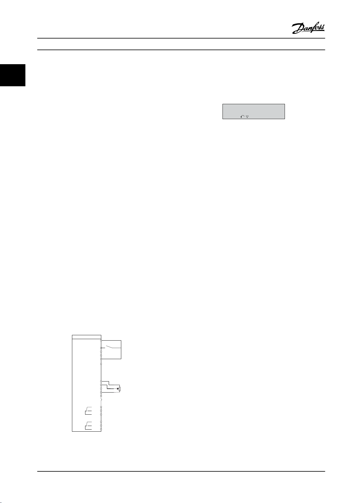
3.1.3 0-3* LCP Custom Readout and Display
It is possible to customize the display elements for various
purposes.
Custom readout
The calculated value to be shown is based on settings in
parameter 0-30 Custom Readout Unit,
parameter 0-31 Custom Readout Min Value (linear only),
parameter 0-32 Custom Readout Max Value,
parameter 4-14 Motor Speed High Limit [Hz], and actual
speed.
Figure 3.1 Custom Readout
The relation depends on the type of unit selected in
parameter 0-30 Custom Readout Unit:
Unit type Speed relation
Dimensionless
Speed
Flow, volume
Flow, mass
Velocity
Length
Temperature
Pressure Quadratic
Power Cubic
Table 3.1 Speed Relation
0-30 Custom Readout Unit
Option: Function:
MG18B522 Danfoss A/S © 05/2018 All rights reserved. 29
Text
Linear
Program a value to be shown in the
display of the LCP. The value has a linear,
squared, or cubed relation to speed. This
relation depends on the unit selected (see
0-30 Custom Readout Unit
Option: Function:
Table 3.1). The actual calculated value can
be read in parameter 16-09 Custom
Readout.
[0] None
[1] * %
[5] PPM
[10] l/Min
[11] RPM
[12] Pulse/s
[20] l/s
[21] l/min
[22] l/h
[23] m3/s
[24] m3/min
[25] m3/h
[30] kg/s
[31] kg/min
[32] kg/h
[33] t/min
[34] t/h
[40] m/s
[41] m/min
[45] m
[60] Degree Celsius
[70] mbar
[71] bar
[72] Pa
[73] kPa
[74] m Wg
[80] kW
[120] GPM
[121] gal/s
[122] gal/min
[123] gal/h
[124] CFM
[127] ft3/h
[140] ft/s
[141] ft/min
[160] Degree Fahr
[170] psi
[171] lb/in2
[172] in WG
[173] ft WG
[180] hp
0-31 Custom Readout Min Value
Range: Function:
0 CustomRea-
doutUnit*
[ 0 -
999999.99
This parameter sets the
minimum value of the custom-
3 3
Page 32

Parameters
VLT® HVAC Basic Drive FC 101
0-31 Custom Readout Min Value
Range: Function:
CustomRea-
doutUnit]
33
dened readout (occurs at 0
speed). It is only possible to
select a value dierent from 0
when selecting a linear unit in
parameter 0-30 Custom Readout
Unit. For quadratic and cubic
units, the minimum value is 0.
0-32 Custom Readout Max Value
Range: Function:
100 Custom-
ReadoutUnit*
[ 0.0 -
999999.99
CustomRea-
doutUnit]
This parameter sets the
maximum value to be shown
when the speed of the motor
has reached the set value for
parameter 4-14 Motor Speed
High Limit [Hz].
0-42 [Auto on] Key on LCP
Option: Function:
[0] Disabled To avoid unintended start of the frequency
converter from the LCP, select [0] Disabled.
[1] * Enabled [Auto On] is enabled.
0-44 [O/Reset] Key on LCP
Option: Function:
[0] Disabled Disable the o/reset key.
[1] * Enabled Enable both o and reset functions.
[7] Enable Reset
Only
Enable the reset function, and disable the
o function to avoid unintended stop of
the frequency converter.
3.1.5 0-5* Copy/Save
Copy parameter settings between set-ups and to/from the
0-37 Display Text 1
Range: Function:
[0 - 0 ] Use this parameter to write an individual text string
to be read via serial communication. Device ID can
be included.
Only used when running BACnet.
0-38 Display Text 2
LCP.
0-50 LCP Copy
Option: Function:
[0] * No copy
[1] All to LCP Copies all parameters in all set-ups from the
frequency converter memory to the LCP
memory. For service purposes, copy all
parameters to the LCP after commissioning.
Range: Function:
[0 - 0 ] Use this parameter to write an individual text string
to be read via serial communication.
Only used when running BACnet.
0-39 Display Text 3
Range: Function:
[0 - 0 ] Use this parameter to write an individual text string
to be read via serial communication.
Only used when running BACnet.
3.1.4 0-4* LCP
[2] All from
LCP
[3] Size indep.
from LCP
[10] Delete LCP
copy data
Copies all parameters in all set-ups from the
LCP memory to the frequency converter
memory.
Copies only the parameters that are
independent of the motor size. The latter
selection can be used to program several
frequency converters with the same function
without disturbing motor data that is already
set.
Delete copied parameters in LCP. This function
requires that LCP version is greater than or
equal to V11.00.
Enable, disable, and password protect individual keys on
the LCP.
0-40 [Hand on] Key on LCP
Option: Function:
[0] Disabled To avoid unintended start of the frequency
converter in hand-on mode, select [0] Disabled.
[1] * Enabled [Hand On] is enabled.
30 Danfoss A/S © 05/2018 All rights reserved. MG18B522
0-51 Set-up Copy
Option: Function:
[0] * No copy No function.
[1] Copy from
setup 1
[2] Copy from
setup 2
[9] Copy from
Factory setup
Copy from set-up 1 to set-up 2.
Copy from set-up 2 to set-up 1.
Copy factory setting to programming set-
up (selected in parameter 0-11 Programming
Set-up).
Page 33

Parameters Programming Guide
3.1.6 0-6* Password
0-60 Main Menu Password
Range: Function:
0* [0 - 999 ] Dene the password for access to the Main Menu
via the [Main Menu] key. Setting the value to 0
disables the password function. This parameter
hides after a password is dened.
0-61 Access to Main Menu w/o Password
Option: Function:
[0] * Full access Disable the password dened in
parameter 0-60 Main Menu Password.
[1] LCP: Read only Prevent unauthorized editing of Main Menu
parameters.
[2] LCP: No access Prevent unauthorized viewing and editing
of Main Menu parameters.
[3] Bus: Read only
[5] All: Read only
3 3
MG18B522 Danfoss A/S © 05/2018 All rights reserved. 31
Page 34

Parameters
VLT® HVAC Basic Drive FC 101
3.2 Main Menu - Load and Motor - Group 1
Parameters related to the motor nameplate load compensations and application load type.
33
3.2.1 1-0* General Settings
1-00 Conguration Mode
Option: Function:
NOTICE!
This parameter cannot be adjusted while
the motor is running.
[0]*Open
Loop
[3] Process
Closed
Loop
1-01 Motor Control Principle
Motor speed is determined by applying a speed
reference or by setting the wanted speed when
in hand-on mode.
Open loop is also used if the frequency
converter is part of a closed-loop control system
based on an external PI controller providing a
speed reference signal as output.
NOTICE!
When set for Closed Loop, the commands
Reversing and Start Reversing do not
reverse the direction of the motor.
A reference from the built-in PI controller
determines the motor speed. The built-in PI
controller varies the motor speed as of a closed-
loop control process (for example, constant
pressure or ow). Congure the PI controller in
parameter group 20-** Drive Closed Loop.
1-03 Torque Characteristics
Option: Function:
[1]*Variable
Torque
[3] Auto
Energy
Optim.
For speed control of centrifugal pumps and fans.
Also to be used when controlling more than 1
motor from the same frequency converter (for
example, multiple condenser fans or cooling
tower fans). Provides a voltage that is optimized
for a squared torque load characteristic of the
motor.
For optimum energy ecient speed control of
centrifugal pumps and fans, it provides a
voltage that is optimized for a squared torque
load characteristic of the motor. In addition, the
AEO feature adapts the voltage exactly to the
current load situation, thereby reducing energy
consumption and audible noise from the motor.
1-06 Clockwise Direction
Option: Function:
NOTICE!
This parameter cannot be adjusted while
the motor is running.
This parameter denes the term clockwise
corresponding to the LCP direction arrow. Used for
easy change of direction of shaft rotation without
swapping motor wires.
[0] * Normal The motor shaft turns in clockwise direction when
frequency converter is connected U⇒U; V⇒V; and
W⇒W to motor.
[1] Inverse The motor shaft turns in counterclockwise
direction when frequency converter is connected
U⇒U; V⇒V; and W⇒W to motor.
Option: Function:
[0] U/f
[1] * VVC+
NOTICE!
When running U/f, control slip and load
compensations are not included.
Used for parallel-connected motors and/or special
motor applications. Set the U/f settings in
parameter 1-55 U/f Characteristic - U and
parameter 1-56 U/f Characteristic - F.
NOTICE!
When parameter 1-10 Motor Construction is
set to PM-enabled options, only VVC+ option
1-08 Motor Control Bandwidth
Option: Function:
[0] High Suitable for highly dynamic response.
[1] * Medium Suitable for smooth steady-state operation.
[2] Low Suitable for smooth steady-state operation with
lowest dynamic response.
[3] Adaptive 1 Suitable for smooth steady-state operation with
extra active damping.
[4] Adaptive 2 This is an alternative to [3] Adaptive 1, which
focuses on low-inductance PM motors.
is available.
Normal running mode, including slip and load
compensations.
32 Danfoss A/S © 05/2018 All rights reserved. MG18B522
Page 35

Parameters Programming Guide
3.2.2 1-10 to 1-13 Motor Selection
NOTICE!
This parameter group cannot be adjusted while the
motor is running.
The following parameters are active ('x') depending on the
setting of parameter 1-10 Motor Construction.
[1] PM,
Parameter 1-10 Motor
Construction
Parameter 1-00 Conguration
Mode
Parameter 1-03 Torque Character-
istics
Parameter 1-06 Clockwise
Direction
Parameter 1-08 Motor Control
Bandwidth
Parameter 1-14 Damping Gain x x
Parameter 1-15 Low Speed Filter
Time Const.
Parameter 1-16 High Speed Filter
Time Const.
Parameter 1-17 Voltage Filter Time
Const.
Parameter 1-20 Motor Power [kW ] x
Parameter 1-22 Motor Voltage x
Parameter 1-23 Motor Frequency x
Parameter 1-24 Motor Current x x x
Parameter 1-25 Motor Nominal
Speed
Parameter 1-26 Motor Cont. Rated
Torque
Parameter 1-29 Automatic Motor
Adaption (AMA)
Parameter 1-30 Stator Resistance
(Rs)
Parameter 1-33 Stator Leakage
Reactance (X1)
Parameter 1-35 Main Reactance
(Xh)
Parameter 1-37 d-axis Inductance
(Ld)
Parameter 1-38 q-axis Inductance
(Lq)
Parameter 1-39 Motor Poles x x x
Parameter 1-40 Back EMF at 1000
RPM
[0]
Asynchron
salient
x x x
x
x x x
x x x
x x
x x
x x
x x x
x x
x x x
x x x
x
x
x x
x
x x
non-
SPM
[3] PM,
salient
IPM,
Sat.
[1] PM,
Parameter 1-10 Motor
Construction
Parameter 1-42 Motor Cable
Length
Parameter 1-43 Motor Cable
Length Feet
Parameter 1-44 d-axis Inductance
Sat. (LdSat)
Parameter 1-45 q-axis Inductance
Sat. (LqSat)
Parameter 1-46 Position Detection
Gain
Parameter 1-48 Current at Min
Inductance for d-axis
Parameter 1-49 Current at Min
Inductance for q-axis
Parameter 1-50 Motor Magneti-
sation at Zero Speed
Parameter 1-52 Min Speed Normal
Magnetising [Hz]
Parameter 1-55 U/f Characteristic
- U
Parameter 1-56 U/f Characteristic
- F
Parameter 1-62 Slip Compensation x
Parameter 1-63 Slip Compensation
Time Constant
Parameter 1-64 Resonance
Dampening
Parameter 1-65 Resonance
Dampening Time Constant
Parameter 1-66 Min. Current at
Low Speed
Parameter 1-70 Start Mode x x
Parameter 1-71 Start Delay x x x
parameter 1-72 Start Function x x x
Parameter 1-73 Flying Start x x x
Parameter 1-80 Function at Stop x x x
Parameter 1-90 Motor Thermal
Protection
parameter 2-00 DC Hold Current x x x
Parameter 2-01 DC Brake Current x x x
Parameter 2-02 DC Braking Time x x x
Parameter 2-04 DC Brake Cut-in
Speed [Hz]
Parameter 2-06 Parking Current x x
Parameter 2-07 Parking Time x x
Parameter 2-10 Brake Function x x x
Parameter 2-16 AC Brake Max.
Current
[0]
Asynchron
salient
x x x
x x x
x
x
x x
x
x
x
x
x
x
x
x
x
x x
x x x
x x x
x
non-
SPM
[3] PM,
salient
IPM,
Sat.
3 3
MG18B522 Danfoss A/S © 05/2018 All rights reserved. 33
Page 36

Parameters
VLT® HVAC Basic Drive FC 101
[1] PM,
Parameter 1-10 Motor
Construction
33
Parameter 2-17 Over-voltage
Control
Parameter 4-10 Motor Speed
Direction
Parameter 4-14 Motor Speed High
Limit [Hz]
Parameter 4-18 Current Limit x x x
Parameter 4-19 Max Output
Frequency
Parameter 4-58 Missing Motor
Phase Function
Parameter 14-01 Switching
Frequency
Parameter 14-03 Overmodulation x x x
Parameter 14-07 Dead Time
Compensation Level
Parameter 14-08 Damping Gain
Factor
Parameter 14-09 Dead Time Bias
Current Level
Parameter 14-10 Mains Failure x x x
Parameter 14-11 Mains Fault
Voltage Level
Parameter 14-12 Function at
Mains Imbalance
Parameter 14-27 Action At
Inverter Fault
Parameter 14-40 VT Level x x x
Parameter 14-41 AEO Minimum
Magnetization
Parameter 14-44 d-axis current
optimization for IPM
Parameter 14-50 RFI Filter x
Parameter 14-51 DC-Link Voltage
Compensation
Parameter 14-55 Output Filter x x x
Parameter 14-64 Dead Time
Compensation Zero Current Level
Parameter 14-65 Speed Derate
Dead Time Compensation
Parameter 30-22 Locked Rotor
Protection
Parameter 30-23 Locked Rotor
Detection Time [s]
Table 3.2 Active Parameters
[0]
Asynchron
salient
x x x
x x x
x x x
x x x
x x x
x x x
x x x
x x x
x x x
x x x
x x x
x x x
x x x
x
x x x
x x x
x x x
x x
x x
non-
SPM
[3] PM,
salient
IPM,
Sat.
1-10 Motor Construction
Option: Function:
[0] * Asynchron For asynchronous motors.
[1] PM, non-
salient SPM
[3] PM, salient
IPM, Sat.
3.2.3
1-14 to 1-17 VVC+ PM
For permanent magnet (PM) motors with
surface-mounted (non-salient) magnets.
Refer to parameter 1-14 Damping Gain to
parameter 1-17 Voltage lter time const. for
details about optimizing the motor
operation.
For permanent magnet (PM) motors with
interior (salient) magnets, with inductance
saturation control.
The default control parameters for VVC+ PM motor control
core are optimized for applications and inertia load in the
range of 50>Jl/Jm>5. Jl is load inertia from the application
and Jm is machine inertia.
For low inertia applications (Jl/Jm<5), it is recommended
that parameter 1-17 Voltage lter time const. is increased
with a factor of 5–10. Sometimes,
parameter 14-08 Damping Gain Factor should also be
reduced to improve performance and stability.
For high-inertia applications (Jl/Jm>50), increase
parameter 1-15 Low Speed Filter Time Const. and
parameter 1-16 High Speed Filter Time Const. to improve
performance and stability.
For high load at low speed (<30% of rated speed), it is
recommended that parameter 1-17 Voltage Filter Time Const.
is increased due to non-linearity in the inverter at low
speed.
1-14 Damping Gain
Range: Function:
120%* [0 -
250 %]
The parameter stabilizes the PM motor to ensure
smooth and stable operation. The value of
damping gain controls the dynamic performance
of the PM motor. Low damping gain results in
high dynamic performance and a high value
results in a low dynamic performance. The
dynamic performance is related to the motor data
and load type. If the damping gain is too high or
low, the control becomes unstable.
1-15 Low Speed Filter Time Const.
Range: Function:
Size
related*
[0.01 -
20 s]
High-pass lter damping time constant
determines the response time to load
steps. Obtain quick control through a
short damping time constant. However,
if this value is too short, the control
34 Danfoss A/S © 05/2018 All rights reserved. MG18B522
Page 37

Parameters Programming Guide
1-15 Low Speed Filter Time Const.
Range: Function:
becomes unstable. This time constant is
used below 10% rated speed.
1-16 High Speed Filter Time Const.
Range: Function:
Size
related*
[0.01 -
20 s]
High-pass lter damping time constant
determines the response time to load
steps. Obtain quick control through a
short damping time constant. However,
if this value is too short, the control
becomes unstable. This time constant is
used above 10% rated speed.
1-17 Voltage lter time const.
Range: Function:
Size
related*
[0.001 - 1s]Machine supply voltage lter time
constant is used for reducing the
inuence of high frequency ripples and
system resonances in the calculation of
machine supply voltage. Without this
lter, the ripples in the currents can
distort the calculated voltage and aect
the stability of the system.
3.2.4 1-2* Motor Data I
This parameter group comprises input data from the
nameplate on the connected motor.
3 3
NOTICE!
These parameters cannot be adjusted while the motor is
running.
NOTICE!
Changing the value of these parameters aects the
setting of other parameters.
1-20 Motor Power
Enter the nominal motor power in kW/hp according to the motor
nameplate data. The default value corresponds to the nominal
rated output of the unit.
This parameter cannot be adjusted while the motor is running.
Option: Function:
[2] 0.12 kW - 0.16 hp
[3] 0.18 kW - 0.25 hp
[4] 0.25 kW - 0.33 hp
[5] 0.37 kW - 0.5 hp
[6] 0.55 kW - 0.75 hp
[7] 0.75 kW - 1 hp
[8] 1.1 kW - 1.5 hp
[9] 1.5 kW - 2 hp
[10] 2.2 kW - 3 hp
[11] 3 kW - 4 hp
[12] 3.7 kW - 5 hp
[13] 4 kW - 5.4 hp
[14] 5.5 kW - 7.5 hp
[15] 7.5 kW - 10 hp
[16] 11 kW - 15 hp
[17] 15 kW - 20 hp
[18] 18.5 kW - 25 hp
[19] 22 kW - 30 hp
[20] 30 kW - 40 hp
[21] 37 kW - 50 hp
[22] 45 kW - 60 hp
[23] 55 kW - 75 hp
[24] 75 kW - 100 hp
[25] 90 kW - 120 hp
[26] 110 kW - 150 hp
1-22 Motor Voltage
Range: Function:
Size
related*
MG18B522 Danfoss A/S © 05/2018 All rights reserved. 35
[50 - 1000V]Enter the nominal motor voltage
according to the motor nameplate
data. The default value corresponds to
the nominal rated output of the unit.
Page 38
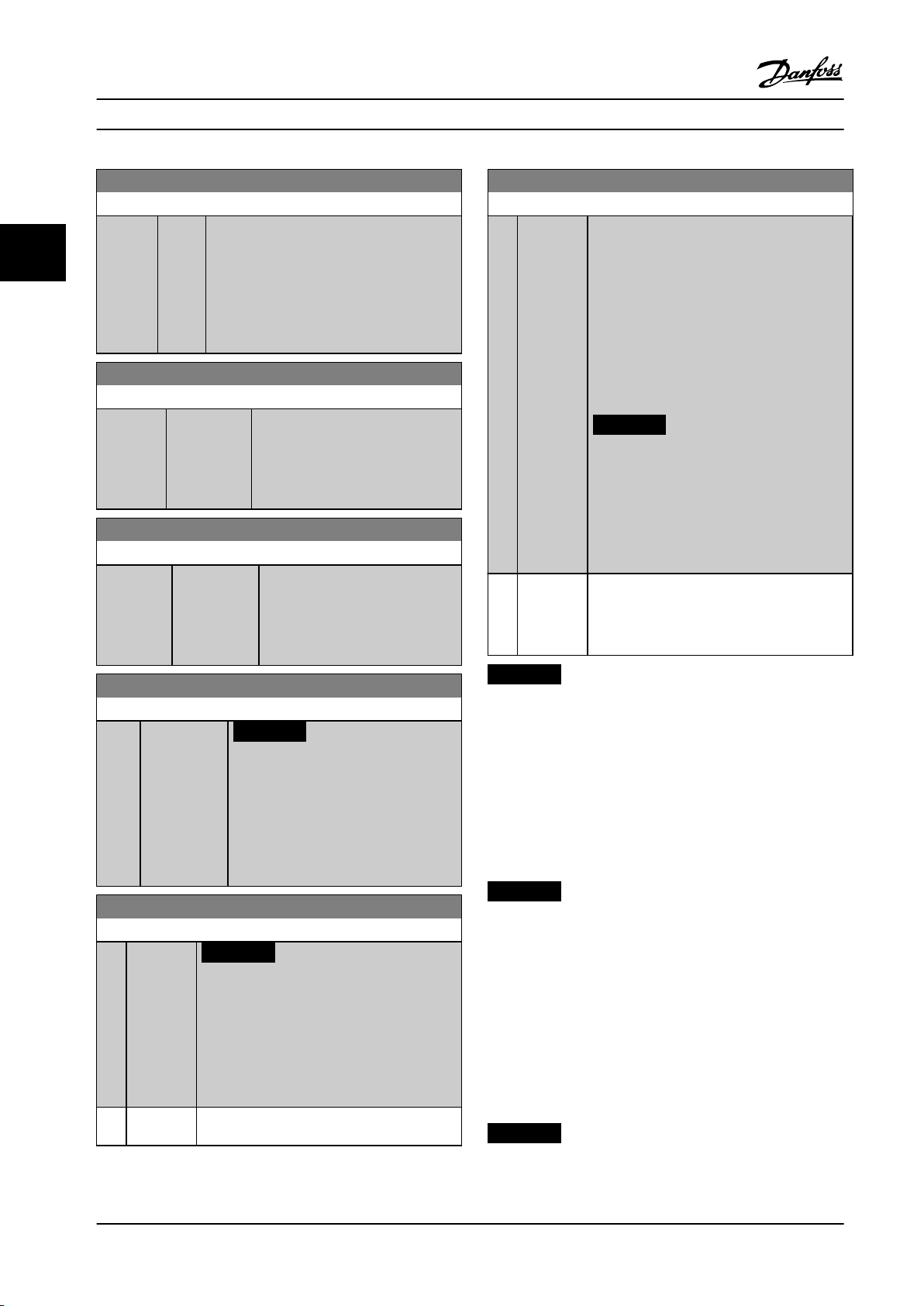
Parameters
VLT® HVAC Basic Drive FC 101
1-23 Motor Frequency
Range: Function:
Size
related*
33
[20 -
400
Hz]
Select the motor frequency value from the
motor nameplate data. For 87 Hz operation
with 230/400 V motors, set the nameplate
data for 230 V/50 Hz. Adapt
parameter 4-14 Motor Speed High Limit [Hz]
and parameter 3-03 Maximum Reference to the
87 Hz application.
1-24 Motor Current
Range: Function:
Size
related*
[ 0.01 -
1000.00 A]
Enter the nominal motor current
value from the motor nameplate
data. This data is used for calculating
motor torque, motor thermal
protection, and so on.
1-25 Motor Nominal Speed
Range: Function:
Size related* [50 - 60000
RPM]
Enter the nominal motor speed
value from the motor nameplate
data. This data is used for
calculating automatic motor
compensations.
1-29 Automatic Motor Adaption (AMA)
Option: Function:
[1] Enable
Complete
AMA
When parameter 1-10 Motor Construction is set
to [0] Asynchron, perform AMA of
parameter 1-30 Stator Resistance (Rs),
parameter 1-33 Stator Leakage Reactance (X1),
and parameter 1-35 Main Reactance (Xh).
When parameter 1-10 Motor Construction is set
to options that enable permanent motors,
perform AMA of parameter 1-30 Stator
Resistance (Rs), and parameter 1-37 d-axis
Inductance (Ld).
NOTICE!
Terminal 27 Digital Input
(parameter 5-12 Terminal 27 Digital Input)
has coast inverse as the default setting.
This means that AMA cannot be
performed if there is no 24 V to terminal
27.
[2] Enable
Reduced
AMA
Performs a reduced AMA of the stator
resistance Rs in the system only. Select this
option if an LC lter is used between the
frequency converter and the motor.
1-26 Motor Cont. Rated Torque
Range: Function:
0 Nm* [0.1 -
10000.0 Nm]
NOTICE!
Changing this parameter aects
settings of other parameters.
This parameter is available only when
parameter 1-10 Motor Construction is set
to options that enable permanent motor
mode.
1-29 Automatic Motor Adaption (AMA)
Option: Function:
NOTICE!
This parameter cannot be adjusted while
the motor is running.
The AMA function optimizes dynamic motor
performance by automatically optimizing the
advanced motor parameters while the motor is
stationary.
[0]*O No function
NOTICE!
When parameter 1-10 Motor Construction is set to options
that enable permanent motor mode, the only option
available is [1] Enable Complete AMA.
Activate the AMA function by pressing [Hand On] after
selecting [1] Enable Complete AMA or [2] Enable Reduced
AMA. After a normal sequence, the display reads: Press [OK]
to nish AMA. After pressing [OK], the frequency converter
is ready for operation.
NOTICE!
For the best adaptation of the frequency
•
converter, run AMA on a cold motor.
AMA cannot be performed while the motor is
•
running.
AMA cannot be performed on a motor with a
•
bigger power rating than the frequency
converter, for example, when a 5.5 kW (7.4 hp)
motor is connected to a 4 kW (5.4 hp)
frequency converter.
NOTICE!
Avoid generating external torque during AMA.
36 Danfoss A/S © 05/2018 All rights reserved. MG18B522
Page 39

Parameters Programming Guide
NOTICE!
If one of the settings in parameter group 1-2* Motor Data
is changed, the advanced motor parameters,
parameter 1-30 Stator Resistance (Rs) to
parameter 1-39 Motor Poles, return to default setting.
NOTICE!
Perform a full AMA without lter only, while reduced
AMA should be run with a lter.
3.2.5 1-3* Motor Data II
This parameter group comprises input data from the
nameplate on the connected motor.
NOTICE!
These parameters cannot be adjusted while the motor is
running.
1-30 Stator Resistance (Rs)
Range: Function:
Size related* [ 0.0 - 9999.000
Ohm]
Set the stator resistance value.
Enter the value from a motor
datasheet or perform an AMA on
a cold motor.
1-37 d-axis Inductance (Ld)
Range: Function:
Size related* [ 0 - 65535 mH] Obtain the value from the
permanent magnet motor
datasheet.
1-38 q-axis Inductance (Lq)
Range: Function:
Size
related*
[ 0.000 -
65535 mH]
Set the value of the q-axis
inductance. Obtain the value from
the permanent magnet motor
datasheet. The value cannot be
changed when the motor is running.
1-39 Motor Poles
Range: Function:
Size
related*
[2 -
100 ]
Enter the number of motor poles. The
motor pole value is always an even
number, because it refers to the total
pole number, not pairs of poles.
3.2.6 1-4* Motor Data III
This parameter group comprises input data from the
nameplate on the connected motor.
3 3
1-33 Stator Leakage Reactance (X1)
Range: Function:
Size related* [ 0.0 - 9999.000 Ohm] Set stator leakage
reactance of motor.
1-35 Main Reactance (Xh)
Range: Function:
Size
related*
[ 0.0 -
9999.00
Ohm]
Set the main reactance of the motor using
1 of these methods:
Run an AMA on a cold motor.
•
The frequency converter
measures the value from the
motor.
Enter the Xh value manually.
•
Obtain the value from the motor
supplier.
Use the Xh default setting. The
•
frequency converter establishes
the setting based on the motor
nameplate data.
NOTICE!
These parameters cannot be adjusted while the motor is
running.
1-40 Back EMF at 1000 RPM
Range: Function:
Size related* [1 - 9000 V ] Line-line RMS back EMF voltage at
1000 RPM.
1-42 Motor Cable Length
Range: Function:
50 m* [0 - 100 m] Set the motor cable length during commis-
sioning.
1-43 Motor Cable Length Feet
Range: Function:
164 ft* [0 - 328 ft] Set the motor cable length during commis-
sioning.
1-44 d-axis Inductance Sat. (LdSat)
Range: Function:
Size
related*
[ 0 -
65535
mH]
This parameter corresponds to the
inductance saturation of Ld. Ideally, this
parameter has the same value as
MG18B522 Danfoss A/S © 05/2018 All rights reserved. 37
Page 40

Magn. current
130BB780.10
Hz
Par.1-50
90%
Par.1-52
Parameters
VLT® HVAC Basic Drive FC 101
1-44 d-axis Inductance Sat. (LdSat)
3.2.7 1-5* Load Indep. Setting
Range: Function:
parameter 1-37 d-axis Inductance (Ld).
33
However, if the motor supplier provides
an induction curve, enter the induction
value here, which is 200% of the
nominal current.
1-45 q-axis Inductance Sat. (LqSat)
Range: Function:
Size
related*
[ 0 -
65535
mH]
This parameter corresponds to the
inductance saturation of Lq. Ideally, this
parameter has the same value as
parameter 1-38 q-axis Inductance (Lq).
However, if the motor supplier provides
an induction curve, enter the induction
value here, which is 200% of the
nominal current.
Parameters for load-independent motor settings.
1-50 Motor Magnetisation at Zero Speed
Range: Function:
100%* [0 -
Use this parameter along with parameter 1-52 Min
300 %
Speed Normal Magnetising [Hz] to obtain a
]
dierent thermal load on the motor when running
at low speed.
Enter a value that is a percentage of the rated
magnetizing current. If the setting is too low, the
torque on the motor shaft may be reduced.
Figure 3.2 Motor Magnetization
1-46 Position Detection Gain
Range: Function:
100 %* [ 20 -
200 %]
1-48 Current at Min Inductance for d-axis
Range: Function:
100 %* [ 20 - 200 %] Use this parameter to set the inductance
1-49 Current at Min Inductance for q-axis
Range: Function:
100 %* [ 20 -
200 %]
Use this parameter to adjust the height of
the test pulse during position detection at
start. This parameter is valid from software
version 2.80.
saturation point.
This parameter species the saturation curve of
the q-inductance values. From 20–100% of this
parameter, the inductances are linearly
approximated due to parameter 1-37 d-axis
Inductance (Ld), parameter 1-38 q-axis Inductance
(Lq), parameter 1-44 d-axis Inductance Sat.
(LdSat), and parameter 1-45 q-axis Inductance
Sat. (LqSat). Below and above they are specied
by the corresponding parameters. Parameters
are related to the motor nameplate load
compensations, the application load type, and
the electronic brake function for quick stop/
hold of the motor.
1-52 Min Speed Normal Magnetising [Hz]
Range: Function:
1 Hz* [0.1 - 10.0
Hz]
Set the required frequency for normal
magnetizing current.
Use this parameter along with
parameter 1-50 Motor Magnetisation at Zero
Speed. See Figure 3.2.
1-55 U/f Characteristic - U
Array [6]
Range: Function:
Size related* [0 - 999V]Enter voltage at each frequency point
to form a U/f characteristic matching
the motor. Frequency points are
dened in parameter 1-56 U/f Charac-
teristic - F.
1-56 U/f Characteristic - F
Array[6]
Range: Function:
Size
related*
[ 0 -
400.0
Hz]
Enter frequency points to form a U/f charac-
teristic matching the motor. Voltage at each
point is dened in parameter 1-55 U/f Charac-
teristic - U.
Make a U/f characteristic based on 6 denable
voltages and frequencies, see Figure 3.3.
Simplify U/f characteristics by merging 2 or
more points (voltages and frequencies). Set
the points at equal values.
38 Danfoss A/S © 05/2018 All rights reserved. MG18B522
Page 41

Parameters Programming Guide
1-56 U/f Characteristic - F
Array[6]
Range: Function:
Figure 3.3 U/f Characteristic
3.2.8 1-6* Load Depen. Setting
Parameters for adjusting the load-dependent motor
settings.
1-62 Slip Compensation
Range: Function:
Size
related*
1-63 Slip Compensation Time Constant
Range: Function:
0.1 s* [0.05 - 5 s] Enter the slip compensation reaction speed.
1-64 Resonance Dampening
Range: Function:
100%* [0 -
1-65 Resonance Dampening Time Constant
Range: Function:
0.005 s* [0.001 -
500 %]
0.050 s]
[-400 -
400 %]
Enter the % value for slip compensation
to compensate for tolerances in the
value of n
calculated automatically, which is based
on the nominal motor speed n
A high value results in slow reaction, and a
low value results in quick reaction. If low-
frequency resonance problems occur, use a
longer time setting.
Enter the resonance damping value. Set
parameter 1-64 Resonance Dampening and
parameter 1-65 Resonance Dampening Time
Constant to help eliminate high-frequency
resonance problems. To reduce resonance
oscillation, increase the value of
parameter 1-64 Resonance Dampening.
Set parameter 1-64 Resonance Dampening
and parameter 1-65 Resonance Dampening
Time Constant to help eliminate high-
frequency resonance problems. Enter the
. Slip compensation is
M,N
M,N
.
1-65 Resonance Dampening Time Constant
Range: Function:
time constant that provides the best
dampening.
3 3
1-66 Min. Current at Low Speed
Range: Function:
50 %* [0 - 120 %] Applies to PM motors only. Increasing the
minimum current improves motor torque at
low speed, but also reduces eciency.
3.2.9 1-7* Start Adjustments
Parameters for conguring special motor start features.
1-70 Start Mode
This parameter is valid since software version 2.80 and later
versions. Use this parameter to select the PM motor start mode
which is to initialize the VVC+ control core for previously free-
running PM motors. This parameter is active for PM motors in
VVC+ mode only if the motor is stopped (or running at low
speed).
Option: Function:
[0] Rotor Detection The rotor detection function estimates the
electrical angle of the rotor and uses the
angle as a starting point. This option is
the standard selection for automation
frequency converter applications. If the
ying start function detects that motor is
running at low speed or is stopped, the
frequency converter can detect the rotor
position (the angle). The frequency
converter then starts the motor from that
angle.
[1] * Parking The parking function applies DC current
across the stator winding and rotates the
rotor to electrical zero position. This
function is typically selected for HVAC
applications. If the ying start function
detects that motor is running at low
speed or is stopped, the frequency
converter sends out a DC current to park
the motor at an angle. The frequency
converter then starts the motor from that
angle.
1-71 Start Delay
Range: Function:
0 s* [0 - 10s]This parameter enables a delay of the starting
time. The frequency converter begins with the
start function selected in parameter 1-72 Start
MG18B522 Danfoss A/S © 05/2018 All rights reserved. 39
Page 42

Parameters
VLT® HVAC Basic Drive FC 101
1-71 Start Delay
3.2.10 1-8* Stop Adjustments
Range: Function:
Function. Set the start delay time until
acceleration is to begin.
33
1-72 Start Function
Option: Function:
[0] DC Hold/
delay time
[2] * Coast/delay
time
1-73 Flying Start
This function makes it possible to catch a motor that is spinning
freely due to a mains drop-out. Flying start searches in clockwise
direction only. If not successful, a DC brake is activated. If PM-
enabled options are selected, parking is carried out if the speed
is below 2.5–5% of nominal speed, in the time set in
parameter 2-07 Parking Time.
If the speed estimate comes out below 2.5–5% of nominal speed,
the parking function is engaged (see parameter 2-06 Parking
Current and parameter 2-07 Parking Time). Otherwise, the
frequency converter catches the motor at that speed and
resumes normal operation.
The ying start function used for PM motors is based on an
initial speed estimation. The speed is always estimated as the
rst thing after an active start signal is given.
Current limitations of the ying start principle used for PM
motors:
The speed range is up to 100% nominal speed or the
•
eld weakening speed (whichever is lowest).
For high inertia applications (that is, where the load
•
inertia is more than 30 times larger than the motor
inertia).
The motor is energized with
parameter 2-00 DC Hold/Motor Preheat Current
during start delay time.
The frequency converter is coasted during
start delay time (frequency converter o).
Parameters for conguring special motor stop features.
1-80 Function at Stop
Option: Function:
Select this function after a stop command or
after the speed is ramped down to the
settings in parameter 1-82 Min Speed for
Function at Stop [Hz].
[0] * Coast Leaves the motor in free mode.
[1] DC hold /
Motor
Preheat
Energizes the motor with a DC hold current
(see parameter 2-00 DC Hold/Motor Preheat
Current).
1-82 Min Speed for Function at Stop [Hz]
Range: Function:
0 Hz* [0 - 20 Hz] Set the output frequency at which to
activate parameter 1-80 Function at Stop.
1-88 AC Brake Gain
Range: Function:
1.4* [1.0 -
2.0 ]
This parameter is used to set AC brake power
capability (set ramp-down time when inertia is
constant). In the condition that the DC-link
voltage is not higher than DC-link voltage
warning value, the generator torque can be
adjusted with this parameter.
Option: Function:
[0] Disabled
[1] Enabled
40 Danfoss A/S © 05/2018 All rights reserved. MG18B522
Page 43

Parameters Programming Guide
3.2.11 1-9* Motor Temperature
Parameters for conguring the temperature protection
features for the motor.
1-90 Motor Thermal Protection
Option: Function:
Using ETR (electronic thermal relay), the
motor temperature is calculated based on
frequency, current, and time. Danfoss
recommends using the ETR function, if a
thermistor is not present. The functionality is
the same for asynchronous motors and PM
motors.
NOTICE!
ETR calculation is based on motor
data from parameter group 1-2* Motor
Data.
[0] No
protection
[1] Thermistor
warning
[2] Thermistor
trip
[3] ETR warning1If the calculated upper limit of the motor
[4] * ETR trip 1 Start motor thermal calculation based on
[22] ETR Trip -
Extended
Detection
Disables temperature monitoring.
A thermistor gives a warning if the upper
limit of motor temperature range is
exceeded.
If the upper limit of motor temperature
range is exceeded, a thermistor gives an
alarm and makes the frequency converter
trip.
temperature range is exceeded, a warning
occurs.
actual load and time as well as motor
frequency only when the motor current is
above 110% of the nominal motor current.
Start motor thermal calculation based on
actual load and time as well as motor
frequency when the motor current is above
110% of the nominal motor current. Another
situation is to start motor thermal
calculation when the motor current is less
than 110% of the nominal motor current
and trigger current limit.
1-93 Thermistor Source
Option: Function:
NOTICE!
This parameter cannot be adjusted while
the motor is running.
NOTICE!
Set the digital input to [0] PNP - Active at
24 V in parameter 5-03 Digital Input 29
Mode.
Select the input at which the thermistor (PTC
sensor) should be connected. When using an
analog input, the same analog cannot be used
as a reference in parameter 3-15 Reference
Resource 1 to parameter 3-17 Reference Resource 3,
parameter 20-00 Feedback 1 Source,
parameter 20-03 Feedback 2 Source,
parameter 24-06 Fire Mode Reference Source, and
parameter 24-07 Fire Mode Feedback Source.
[0]*None Do not set thermistor source.
[1] Analog
input
AI53
[6] Digital
input 29
Use analog input 53 as thermistor source.
Use digital input 29 as thermistor source.
3 3
MG18B522 Danfoss A/S © 05/2018 All rights reserved. 41
Page 44

Parameters
VLT® HVAC Basic Drive FC 101
3.3 Main Menu - Brakes - Group 2
3.3.1 2-0* DC Brakes
33
Parameters for conguring the DC brake and DC hold
functions.
2-04 DC Brake Cut In Speed
Range: Function:
0 Hz* [ 0 - 500
Hz]
This parameter is for setting the DC-brake
cut-in speed at which parameter 2-01 DC
Brake Current is to be active with a stop
command.
2-00 DC Hold/Motor Preheat Current
Range: Function:
50 %* [0 -
160 %]
NOTICE!
MOTOR OVERHEATING
The maximum value depends on the rated
motor current.
To avoid motor damage caused by
overheating, do not run at 100% for too
long.
2-06 Parking Current
Range: Function:
100%* [0 -
150 %]
Set current as percentage of rated motor
current, parameter 1-24 Motor Current. Active
with parameter 1-73 Flying Start. The parking
current is active during the time period set in
parameter 2-07 Parking Time.
NOTICE!
Parameter 2-06 Parking Current is only
Set holding current as a percentage of the rated
motor current I
Current. Parameter 2-00 DC Hold/Motor Preheat
Current holds the motor function (holding torque)
or pre-heats the motor. This parameter is active if
DC hold is selected in parameter 1-72 Start
Function [0] DC Hold/delay time or
parameter 1-80 Function at Stop [1] DC hold/Motor
Preheat.
in parameter 1-24 Motor
M,N
2-07 Parking Time
Range: Function:
3 s* [0.1 - 60s]Set the duration of the parking current time set
active when 1 of the PM motor
construction options is selected in
parameter 1-10 Motor Construction.
in parameter 2-06 Parking Current. Active with
parameter 1-73 Flying Start.
2-01 DC Brake Current
Range: Function:
50%* [0 -
NOTICE!
150 %
MOTOR OVERHEATING
]
The maximum value depends on the rated
NOTICE!
Parameter 2-07 Parking Time is only active
when options of parameter 1-10 Motor
Construction are set to enable PM motors.
motor current.
To avoid motor damage caused by
overheating, do not run at 100% for too
long.
Set current as % of rated motor current,
parameter 1-24 Motor Current. When speed is
below the limit set in parameter 2-04 DC Brake Cut
In Speed, or when the DC-brake inverse function is
active (in parameter group 5-1* Digital Inputs set to
[5] DC-brake inverse; or via the serial port), a DC-
brake current is applied on a stop command. See
parameter 2-02 DC Braking Time for duration.
2-02 DC Braking Time
Range: Function:
10 s* [0 - 60 s] Set the duration of the DC-brake current set in
parameter 2-01 DC Brake Current, once
activated.
42 Danfoss A/S © 05/2018 All rights reserved. MG18B522
Page 45

Parameters Programming Guide
3.3.2 2-1* Brake Energy Function
Parameter group for selecting dynamic brake parameters.
2-10 Brake Function
Option: Function:
[0] * O The brake resistor is not active.
[2] AC brake AC brake is active.
2-16 AC Brake, Max current
Range: Function:
100 %* [0 - 160 %] Enter the maximum permissible current
when using the AC brake to avoid
overheating motor windings.
2-17 Over-voltage Control
Option: Function:
Select whether to enable OVC during ramp
down, which reduces the risk of frequency
converter trip due to overvoltage on the DC
link caused by generative power from load.
[0] Disabled No OVC required.
[1] Enabled
(not at stop)
[2] * Enabled Activates OVC.
Activates OVC when the frequency converter
is not in the stop state.
3 3
NOTICE!
The ramp time is automatically
adjusted to avoid tripping of the
frequency converter.
MG18B522 Danfoss A/S © 05/2018 All rights reserved. 43
Page 46

P3-03
P3-02
0 50 100%
P3-10
130BB036.10
Relative
Z=X+X*Y/100
Resulting
actual
reference
Y
X
130BA059.12
Z
Parameters
VLT® HVAC Basic Drive FC 101
3.4 Main Menu–Reference/Ramps–Group 3
3.4.1 3-0* Reference Limits
33
Parameters for setting the reference unit, limits, and
ranges.
Also see parameter group 20-0* Feedback for information on
3-10 Preset Reference
Range: Function:
0 %* [-100 -
100 %]
Enter up to 8 dierent preset references (0–7)
in this parameter, using array programming. For
selecting dedicated references, select preset
reference bit 0/1/2 [16], [17], or [18] for the
corresponding digital inputs in parameter group
5-1* Digital Inputs.
settings in closed loop.
3-02 Minimum Reference
Range: Function:
0* [-4999–4999] The minimum reference is the lowest value
obtainable by summing all references.
3-03 Maximum Reference
3-11 Jog Speed [Hz]
Range: Function:
5 Hz* [ 0 - 500.0
Hz]
The jog speed is a xed output speed at
which the frequency converter runs when
the jog function is activated.
See also parameter 3-80 Jog Ramp Time.
Range: Function:
Size
related*
[ -4999.0 - 4999
ReferenceFeed-
backUnit]
3.4.2 3-1* References
The maximum reference is the
highest value obtainable by
summing all references. The
maximum reference unit matches
the selection of conguration in
parameter 1-00 Conguration
Mode.
3-14 Preset Relative Reference
Range: Function:
0 %* [-100
-
100 %]
Dene the xed value in % to be added to the
variable value dened in parameter 3-18 Relative
Scaling Reference Resource.
The sum of xed and variable values (labeled Y in
Figure 3.5) is multiplied by actual reference (labeled
X in Figure 3.5). This product is added to actual
reference X + X ×
100
Y
Figure 3.4 References
Figure 3.5 Preset Relative Reference
3-15 Reference 1 Source
Option: Function:
Select the input to be used for the 1
reference signal. Parameter 3-15 Reference 1
Source, parameter 3-16 Reference 2 Source,
and parameter 3-17 Reference 3 Source
dene up to 3 dierent reference signals.
The sum of these reference signals denes
the actual reference.
[0] No function
[1] * Analog Input
53
[2] Analog Input
54
[7] Pulse input 29
[11] Local bus
reference
st
44 Danfoss A/S © 05/2018 All rights reserved. MG18B522
Page 47

t
acc
t
dec
130BB801.10
P 3-*2
Ramp (X)
Down
Time (Dec)
P 4-14
High-limit
RPM
Reference
P 1-23
Motor
frequency
P 4-12
Low limit
Time
P 3-*1
Ramp (X)Up
Time (Acc)
Parameters Programming Guide
3-16 Reference 2 Source
Option: Function:
Select the input to be used for the 2
reference signal. Parameter 3-15 Reference 1
Source, parameter 3-16 Reference 2 Source,
and parameter 3-17 Reference 3 Source
dene up to 3 dierent reference signals.
The sum of these reference signals denes
the actual reference. See also
parameter 1-93 Thermistor Source.
[0] No function
[1] Analog Input
53
[2] * Analog Input
54
[7] Pulse input 29
[11] Local bus
reference
3-17 Reference 3 Source
Option: Function:
Select the reference input to be used for
the 3rd reference signal.
Parameter 3-15 Reference 1 Source,
parameter 3-16 Reference 2 Source, and
parameter 3-17 Reference 3 Source dene
up to 3 dierent reference signals. The
sum of these reference signals denes the
actual reference.
[0] No function
[1] Analog Input
53
[2] Analog Input
54
[7] Pulse input 29
[11] * Local bus
reference
3.4.3 3-4* Ramp 1
nd
Congure the ramp time parameters for each of the 2
ramps (parameter group 3-4* Ramp 1 and parameter group
3-5* Ramp 2). The ramp time is preset to the minimum
value of 10 ms for all power sizes.
Figure 3.6 Ramps
3-41 Ramp 1 Ramp Up Time
Range: Function:
Size
related*
[0.05 -
3600 s]
Enter acceleration time from 0 Hz to
parameter 1-23 Motor Frequency if
asynchronous motor is selected. Enter
acceleration time from 0 RPM, to
parameter 1-25 Motor Nominal Speed if PM
motor is selected. Select a ramp-up time
such that the output current does not
exceed the current limit in
parameter 4-18 Current Limit during ramping.
See ramp-down time in
parameter 3-42 Ramp 1 Ramp-down Time.
3-42 Ramp 1 Ramp Down Time
Range: Function:
Size
related*
[0.05 -
3600 s]
If asynchronous motor is selected, enter
deceleration time from
parameter 1-23 Motor Frequency to 0 Hz. If
PM motor is selected, enter deceleration
time from parameter 1-25 Motor Nominal
Speed to 0 RPM. Select a ramp-down time
to avoid tripping on overvoltage in the
DC-link.
3 3
MG18B522 Danfoss A/S © 05/2018 All rights reserved. 45
Page 48

Parameters
VLT® HVAC Basic Drive FC 101
3.4.4 3-5* Ramp 2
This parameter group congures ramp 2 parameters.
33
3-51 Ramp 2 Ramp Up Time
Range: Function:
Size
related*
[0.05 -
3600 s]
If asynchronous motor is selected, enter
acceleration time from 0 Hz to
parameter 1-23 Motor Frequency. If PM
motor is selected, enter acceleration time
from 0 RPM to parameter 1-25 Motor
Nominal Speed. Select a ramp-up time such
that the output current does not exceed
the current limit in parameter 4-18 Current
Limit during ramping up.
3-52 Ramp 2 Ramp Down Time
Range: Function:
Size
related*
[0.05 -
3600 s]
Enter deceleration time from
parameter 1-25 Motor Nominal Speed to
0 RPM. Select a ramp-down time such
that the output current does not exceed
the current limit in
parameter 4-18 Current Limit during
ramping down.
3.4.5 3-8* Other Ramps
3-80 Jog Ramp Time
Range: Function:
Size
related*
[0.05
- 3600
s]
Enter the jog ramp time, which is the
acceleration/deceleration time between 0 Hz
to parameter 1-23 Motor Frequency. Ensure
that the resulting output current required for
the given jog ramp time does not exceed the
current limit in parameter 4-18 Current Limit.
The jog ramp time starts after activation of a
jog signal via the control panel, a selected
digital input, or the serial communication
port.
3-81 Quick Stop Ramp Time
Range: Function:
Size
related*
[0.05 -
3600 s]
Enter the quick stop ramp time from the
parameter 1-23 Motor Frequency to 0 Hz.
During ramping, no overvoltage may occur
in the inverter, nor may the generated
current exceed the limit in
parameter 4-18 Current Limit. Quick stop is
activated with a signal on a selected digital
input or via the serial communication port.
46 Danfoss A/S © 05/2018 All rights reserved. MG18B522
Page 49

Parameters Programming Guide
3.5 Main Menu - Limits/Warnings - Group 4
3.5.1 4-1* Motor Limits
Dene current and speed limits for the motor, and the
reaction of the frequency converter when the limits are
exceeded.
4-10 Motor Speed Direction
Option: Function:
[0] Clockwise
[2] * Both
directions
4-12 Motor Speed Low Limit [Hz]
Range: Function:
0 Hz* [ 0 -
400.0 Hz]
4-14 Motor Speed High Limit [Hz]
Range: Function:
Size
related*
[ 0.1 -
400.0 Hz]
4-18 Current Limit
Range: Function:
110%* [0 -
1000 %
]
NOTICE!
The setting in parameter 4-10 Motor
Speed Direction has impact on
parameter 1-73 Flying Start.
Only operation in clockwise direction is
allowed.
Operation in both clockwise and counter-
clockwise directions is allowed.
Enter the minimum limit for motor speed. The
motor speed low limit can be set to
correspond to the minimum output frequency
of the motor shaft. The speed low limit must
not exceed the setting in
parameter 4-14 Motor Speed High Limit [Hz].
Enter the maximum limit for motor speed.
It can be set to match the recommended
maximum motor speed. The motor speed
high limit must exceed the value in
parameter 4-12 Motor Speed Low Limit [Hz].
Motor speed high limit cannot be set
higher than parameter 4-19 Max Output
Frequency.
Enter the current limit for motor and generator
operation (in % of rated motor current). If the
value is higher than maximum rated output from
frequency converter, current is still limited to the
maximum output current of the frequency
converter. If a setting in parameter 1-00 Congu-
ration Mode to parameter 1-25 Motor Nominal
Speed is changed, parameter 4-18 Current Limit is
not automatically reset to the default setting.
4-19 Max Output Frequency
Range: Function:
Size
related*
[ 0 -
Enter the maximum output frequency, which
400
denes the absolute limit on the frequency
Hz]
converter output frequency for improved
safety in applications where unintended
overspeeding must be avoided. This absolute
limit applies to all congurations and is
independent of the setting in
parameter 1-00 Conguration Mode.
When parameter 1-10 Motor Construction is set
to one of the options enabling PM motor
construction, the maximum limit of
parameter 4-19 Max Output Frequency might
be limited by the setting of
parameter 1-40 Back EMF at 1000 RPM due to
avoid a too high Back EMF, which can damage
the frequency converter. If parameter 4-19 Max
Output Frequency is set lower than
parameter 4-14 Motor Speed High Limit [Hz], the
value of parameter 4-14 Motor Speed High Limit
[Hz] is adjusted to the same value of
parameter 4-19 Max Output Frequency automat-
ically.
3.5.2 4-4* Adjustable Warnings 2
4-40 Warning Freq. Low
Range: Function:
Size
related*
4-41 Warning Freq. High
Range: Function:
Size
related*
[ 0 -
Use this parameter to set a lower limit for the
500
frequency range.
Hz]
When the motor speed drops below this limit,
the display reads SPEED LOW. Warning bit 10
is set in parameter 16-94 Ext. Status Word. The
output relay or the digital output can be
congured to indicate this warning. The LCP
warning indicator light is not turned on when
this parameter set limit is reached.
[ 0 -
Use this parameter to set a higher limit for
500
the frequency range.
Hz]
When the motor speed exceeds this limit, the
display reads SPEED HIGH. Warning bit 9 is set
in parameter 16-94 Ext. Status Word. The
output relay or the digital output can be
congured to indicate this warning. The LCP
warning indicator light is not turned on when
this parameter set limit is reached.
3 3
MG18B522 Danfoss A/S © 05/2018 All rights reserved. 47
Page 50

Parameters
VLT® HVAC Basic Drive FC 101
3.5.3 4-5* Adj. Warnings
4-56 Warning Feedback Low
Range: Function:
Dene adjustable warning limits for current. Warnings are
shown on the display, programmed output, or eldbus.
33
4-50 Warning Current Low
Range: Function:
0 A [ 0 - 500A]Enter the I
drops below this limit, a bit in the status word is
set. This value can also be programmed to
produce a signal on the digital output or the
relay output.
4-51 Warning Current High
Range: Function:
Size
related*
[ 0.0 -
500.00 A]
value. When the motor current
LOW
Enter the I
current exceeds this limit, a bit in the
status word is set. This value can also
be programmed to produce a signal on
the digital output or the relay output.
value. When the motor
HIGH
4-57 Warning Feedback High
Range: Function:
4999
ProcessCtrlUnit*
[-4999 - 4999
ProcessCtrlUnit]
4-54 Warning Reference Low
Range: Function:
-4999* [-4999 -
4999 ]
4-55 Warning Reference High
Enter the lower reference limit. When the
actual reference drops below this limit, the
display indicates Ref
in parameter 16-94 Ext. Status Word. The
output relay or the digital output can be
congured to indicate this warning. The LCP
warning indicator light is not turned on when
this parameter set limit is reached.
. Warning bit 20 is set
Low
4-58 Missing Motor Phase Function
Option: Function:
[0] O No alarm is shown if a missing motor phase occurs.
[1] * On An alarm is shown if a missing motor phase occurs.
parameter 16-94 Ext. Status
Word. The output relay or
digital output can be
congured to indicate this
warning. The LCP warning
indicator light is not turned
on when this parameter set
limit is reached.
Use this parameter to set a
higher limit for the feedback
range.
When the feedback exceeds
this limit, the display reads
Feedback High. Warning bit 5
is set in parameter 16-94 Ext.
Status Word. The output relay
or digital output can be
congured to indicate this
warning. The LCP warning
indicator light is not turned
on when this parameter set
limit is reached.
Range: Function:
4999* [-4999 -
4999 ]
4-56 Warning Feedback Low
Range: Function:
-4999
ProcessCtrlUnit*
Use this parameter to set a higher limit for the
reference range.
When the actual reference exceeds this limit,
the display reads Reference High. Warning bit
19 is set in parameter 16-94 Ext. Status Word.
The output relay or the digital output can be
congured to indicate this warning. The LCP
warning indicator light is not turned on when
this parameter set limit is reached.
[-4999 - 4999
ProcessCtrlUnit]
Use this parameter to set a
lower limit for the feedback
range.
When the feedback drops
below this limit, the display
reads Feedback Low. Warning
bit 6 is set in
3.5.4 4-6* Speed Bypass
Dene the speed bypass areas for the ramps. 3 frequency
ranges can be avoided.
4-61 Bypass Speed From [Hz]
Array[3]
Range: Function:
0 Hz [ 0 - 500 Hz] Enter the lower limits of the speeds to be
avoided. Some systems call for avoiding
certain output speeds due to resonance
problems in the system.
4-63 Bypass Speed To [Hz]
Array[3]
Range: Function:
0 Hz* [ 0 - 500 Hz] Some systems call for avoiding certain
output speeds due to resonance problems
48 Danfoss A/S © 05/2018 All rights reserved. MG18B522
Page 51

Parameters Programming Guide
4-63 Bypass Speed To [Hz]
Array[3]
Range: Function:
in the system. Enter the upper limits of the
speeds to be avoided.
3.5.5 Semi-Automatic Bypass Speed Set-up
Use the semi-automatic bypass speed set-up to facilitate
the programming of the frequencies to be skipped due to
resonances in the system.
Procedure:
1. Stop the motor.
NOTICE!
Adjust the ramp times in parameter 3-41 Ramp 1 Ramp
Up Time and parameter 3-42 Ramp 1 Ramp Down Time.
2. Select [1] Enabled in parameter 4-64 Semi-Auto
Bypass Set-up.
3. Press [Hand On] to start the search for frequency
bands causing resonances. The motor ramps up
according to the ramp set.
If the frequencies for a certain resonance band are not
registered in the right order (frequency values stored in
parameter 4-63 Bypass Speed To [Hz] are ≥ the values in
parameter 4-61 Bypass Speed From [Hz]), or if they do not
have the same numbers of registrations for the
parameter 4-61 Bypass Speed From [Hz] and
parameter 4-63 Bypass Speed To [Hz], all registrations are
canceled and the following message is shown: Collected
speed areas overlapping or not determined. Press [Cancel] to
abort.
4-64 Semi-Auto Bypass Set-up
Option: Function:
[0] * O
[1] Enable If this option is selected, speed ranges are automat-
ically swept to identify bands of resonances.
3 3
NOTICE!
Terminal 27 digital input parameter 5-12 Terminal 27
Digital Input has [2] Coast inverse as default setting. If
there is no 24 V to terminal 27, [Hand On] does not start
the motor. If so, connect terminal 12 to terminal 27.
4. When sweeping through a resonance band, press
[OK] on the LCP when leaving the band. The
actual frequency is stored as the rst element in
parameter 4-63 Bypass Speed To [Hz] (array).
Repeat this procedure for each resonance band
identied at the ramp-up (maximum of 3 can be
adjusted).
5. When maximum speed has been reached, the
motor automatically begins to ramp down.
Repeat this procedure when speed is leaving the
resonance bands during the deceleration. The
actual frequencies registered when pressing [OK]
are stored in parameter 4-61 Bypass Speed From
[Hz].
6. When the motor has ramped down to stop, press
[OK]. The parameter 4-64 Semi-Auto Bypass Set-up
automatically resets to o. The frequency
converter stays in hand on mode until [O] or
[Auto On] is pressed.
MG18B522 Danfoss A/S © 05/2018 All rights reserved. 49
Page 52

Parameters
VLT® HVAC Basic Drive FC 101
3.6 Main Menu - Digital In/Out - Group 5
Digital input
function
Description
3.6.1 5-0* Digital I/O Mode
[4] Quick stop inverse Inverted input (NC). Generates a stop in
33
Parameters for conguring the input and output using
NPN and PNP.
NOTICE!
[5] DC brake inverse Inverted input for DC braking (NC). Stops
These parameters cannot be adjusted while the motor is
running.
5-00 Digital Input Mode
Option: Function:
Set NPN or PNP mode for digital inputs 18, 19, and
27. Digital input mode.
[0] * PNP Action on positive directional pulses (0). PNP systems
are pulled down to ground (GND).
[1] NPN Action on negative directional pulses (1). NPN
systems are pulled up to +24 V, internally in the
frequency converter.
[6] Stop inverse The stop inverse function generates the
[7] External Interlock Same function as coast stop, inverse, but
5-03 Digital Input 29 Mode
Option: Function:
[0] * PNP Set to PNP mode for digital inputs 29.
[1] NPN Set to NPN mode for digital inputs 29.
3.6.2 5-1* Digital Inputs
Parameters for conguring the input functions for the
input terminals.
The digital inputs are used for selecting various functions
in the frequency converter. All digital inputs can be set to
the following functions:
Digital input
function
[0] No operation No reaction to signals transmitted to the
[1] Reset Resets the frequency converter after a
[2] Coast inverse Leaves the motor in free mode. Logic
[3] Coast and reset
inverse
Description
terminal.
trip/alarm. Trip lock alarms can be reset.
0⇒coast stop.
Reset and coast stop inverted input (NC).
Leaves the motor in free mode and resets
the frequency converter. Logic 0⇒coast
stop and reset.
[8] Start Select start for a start/stop command.
[9] Latched start If a pulse is applied for a minimum of 2
[10] Reversing Change direction of motor shaft rotation.
[11] Start reversing Use for start/stop and for reversing at the
[14] Jog Used for activating jog speed. See
accordance with the quick-stop ramp time
set in parameter 3-81 Quick Stop Ramp
Time. After ramping down, the shaft is in
free mode.
the motor by energizing it with DC
current for a certain time period, see
parameter 2-01 DC Brake Current. The
function is only active when the value in
parameter 2-02 DC Braking Time is dierent
from 0. This selection is not possible when
parameter 1-10 Motor Construction is set to
[1] PM non-salient SPM.
stop function when the selected terminal
goes from logical level 1 to 0 (not
latched). Stop is performed according to
selected ramp time.
external interlock generates the alarm
message external fault on the display
when the terminal programmed for coast
inverse is logic 0. If programmed for
external interlock, the alarm message is
also active via digital outputs and relay
outputs. If the cause for the external
interlock is removed, the alarm can be
reset using a digital input, eldbus, or the
[Reset] key.
Logic 1 = start, logic 0 = stop. (Default
digital input 18).
ms, the motor starts. The motor stops
when stop inverse is activated.
The reversing signal only changes the
direction of rotation, it does not activate
the start function. Select [2] Both directions
in parameter 4-10 Motor Speed Direction. 0
= normal, 1 = reversing.
same time. Signals on [8] start are not
allowed at the same time. 0 = stop, 1 =
start reversing.
parameter 3-11 Jog Speed [Hz]. (Default
digital input 29).
50 Danfoss A/S © 05/2018 All rights reserved. MG18B522
Page 53

Parameters Programming Guide
Digital input
function
[16] Preset ref bit 0 Enables a selection of 1 of the 8 preset
[17] Preset ref bit 1 Enables a selection of 1 of the 8 preset
[18] Preset ref bit 2 Enables a selection of 1 of the 8 preset
[19] Freeze reference Freeze actual reference. The frozen
[20] Freeze output Freezes actual reference. The frozen
[21] Speed up For digital control of the up/down speed
[22] Speed down Same as [21] Speed up, but reference
[23] Set-up select bit0Selects 1 of the 2 set-ups. Set
[32] Pulse Input Select pulse input when using a pulse
[34] Ramp bit 0 Select which ramp to use. Logic 0 selects
[37] Fire mode A signal applied puts the frequency
Description
references according to Table 3.4.
references according to Table 3.4.
references according to Table 3.4.
reference is now the point of enable/
condition for speed up and speed down
to be used. If speed up/speed down is
used, a speed change always follows ramp
2 (parameter 3-51 Ramp 2 Ramp Up Time
and parameter 3-52 Ramp 2 Ramp Down
Time) in the range
parameter 3-02 Minimum Reference -
parameter 3-03 Maximum Reference.
reference is now the point of enable/
condition for speed up and speed down
to be used. If speed up/speed down is
used, the speed change always follows
ramp 2.
(motor potentiometer). Activate this
function by selecting either freeze
reference or freeze output. When speed
up is activated for less than 400 ms, the
resulting reference is increased by 0.1%. If
speed up is activated for more than 400
ms, the resulting reference ramps
according to ramp 1 in
parameter 3-41 Ramp 1 Ramp Up Time.
decreases.
parameter 0-10 Active Set-up to multi set-
up.
sequence as either reference or feedback.
Scaling is done in parameter group 5-5*
Pulse Input. Available only for terminal 29.
ramp 1, while logic 1 selects ramp 2.
converter into re mode and disregards all
other commands. See parameter group
24-0* Fire Mode.
Digital input
function
[52] Run permissive The input terminal, for which the run
Description
permissive is programmed, must be logic
1 before a start command can be
accepted. Run permissive has a logic AND
function related to the terminal, which is
programmed for [8] Start, [14] Jog, or [20]
Freeze Output. To start running the motor,
both conditions must be fullled. If run
permissive is programmed on multiple
terminals, run permissive only has to be
logic 1 on 1 of the terminals for the
function to be carried out. Run permissive
does not aect the digital output signal
for run request ([8] Start, [14] Jog, or [20]
Freeze Output) programmed in parameter
group 5-3* Digital Outputs, or parameter
group 5-4* Relays.
NOTICE!
If no run permissive signal is applied
but either run, jog, or freeze
commands is activated, the status
line in the display shows either Run
Requested, Jog Requested, or Freeze
Requested.
[53] Hand Start A signal applied puts the frequency
converter into hand on mode as if [Hand
On] is pressed and a normal stop
command is overridden. If the signal is
disconnected, the motor stops. To make
any other start commands valid, assign
another digital input to Auto Start and
apply a signal. The [Hand On] and [Auto
On] keys have no impact. The [O] key
overrides Hand Start and Auto Start. Press
either [Hand On] or [Auto On] to
reactivate Hand Start and Auto Start. If
there is no signal on Hand Start or Auto
Start, the motor stops regardless of any
normal start command applied. If a signal
is applied to both Hand Start and Auto
Start, the function is Auto Start.
[54] Auto start A signal applied puts the frequency
converter into Auto mode as if [Auto On]
is pressed. See also [53] Hand Start.
[60] Counter A (up) Input for increment counting in the SLC
counter.
[61] Counter A (down) Input for decrement counting in the SLC
counter.
[62] Reset Counter A Input for reset of counter A.
3 3
MG18B522 Danfoss A/S © 05/2018 All rights reserved. 51
Page 54

Parameters
VLT® HVAC Basic Drive FC 101
Digital input
function
[63] Counter B (up) Input for increment counting in the SLC
33
[64] Counter B (down) Input for decrement counting in the SLC
[65] Reset Counter B Input for reset of counter B.
[101] Sleep A signal applied puts the frequency
Table 3.3 Digital Input Functions
Selected
preset
reference:
Preset
reference 0
Preset
reference 1
Preset
reference 2
Preset
reference 3
Preset
reference 4
Preset
reference 5
Preset
reference 6
Preset
reference 7
Table 3.4 Selected Preset Reference
5-10 Terminal 18 Digital Input
Parameter for conguring the input function on input terminal
18. Refer to Table 3.3 for setting options.
Option: Function:
[0] No operation
[1] Reset
[2] Coast inverse
[3] Coast and reset inverse
[4] Quick stop inverse
[5] DC-brake inverse
[6] Stop inverse
[7] External Interlock
[8] * Start
[9] Latched start
[10] Reversing
[11] Start reversing
[14] Jog
Description
counter.
counter.
converter into sleep mode.
Preset
reference bit 2
0 0 0
0 0 1
0 1 0
0 1 1
1 0 0
1 0 1
1 1 0
1 1 1
Preset
reference bit 1
Preset
reference bit 0
5-10 Terminal 18 Digital Input
Parameter for conguring the input function on input terminal
18. Refer to Table 3.3 for setting options.
Option: Function:
[16] Preset ref bit 0
[17] Preset ref bit 1
[18] Preset ref bit 2
[19] Freeze reference
[20] Freeze output
[21] Speed up
[22] Speed down
[23] Set-up select bit 0
[34] Ramp bit 0
[37] Fire Mode
[52] Run permissive
[53] Hand start
[54] Auto start
[60] Counter A (up)
[61] Counter A (down)
[62] Reset Counter A
[63] Counter B (up)
[64] Counter B (down)
[65] Reset Counter B
[101] Sleep
[120] Lead Pump Start
[121] Lead Pump Alternation
[130] Pump 1 Interlock
[131] Pump 2 Interlock
[132] Pump 3 Interlock
[133] Pump 4 Interlock
[134] Pump 5 Interlock
5-11 Terminal 19 Digital Input
Parameter for conguring the input function on input terminal
19.
Option: Function:
[0] * No operation
[1] Reset
[2] Coast inverse
[3] Coast and reset inverse
[4] Quick stop inverse
[5] DC-brake inverse
[6] Stop inverse
[7] External Interlock
[8] Start
[9] Latched start
[10] Reversing
[11] Start reversing
[14] Jog
[16] Preset ref bit 0
[17] Preset ref bit 1
52 Danfoss A/S © 05/2018 All rights reserved. MG18B522
Page 55

Parameters Programming Guide
5-11 Terminal 19 Digital Input
Parameter for conguring the input function on input terminal
19.
Option: Function:
[18] Preset ref bit 2
[19] Freeze reference
[20] Freeze output
[21] Speed up
[22] Speed down
[23] Set-up select bit 0
[34] Ramp bit 0
[37] Fire Mode
[52] Run permissive
[53] Hand start
[54] Auto start
[60] Counter A (up)
[61] Counter A (down)
[62] Reset Counter A
[63] Counter B (up)
[64] Counter B (down)
[65] Reset Counter B
[101] Sleep
[120] Lead Pump Start
[121] Lead Pump Alternation
[130] Pump 1 Interlock
[131] Pump 2 Interlock
[132] Pump 3 Interlock
[133] Pump 4 Interlock
[134] Pump 5 Interlock
5-12 Terminal 27 Digital Input
Parameter for conguring the input function on input terminal
27. When parameter 0-03 Regional Settings is set to [0] Interna-
tional, the default value is [2] Coast inverse. When
parameter 0-03 Regional Settings is set to [1] North America, the
default value is [7] External Interlock.
Option: Function:
[0] No operation
[1] Reset
[2] Coast inverse
[3] Coast and reset inverse
[4] Quick stop inverse
[5] DC-brake inverse
[6] Stop inverse
[7] External Interlock
[8] Start
[9] Latched start
[10] Reversing
[11] Start reversing
[14] Jog
[16] Preset ref bit 0
[17] Preset ref bit 1
5-12 Terminal 27 Digital Input
Parameter for conguring the input function on input terminal
27. When parameter 0-03 Regional Settings is set to [0] Interna-
tional, the default value is [2] Coast inverse. When
parameter 0-03 Regional Settings is set to [1] North America, the
default value is [7] External Interlock.
Option: Function:
[18] Preset ref bit 2
[19] Freeze reference
[20] Freeze output
[21] Speed up
[22] Speed down
[23] Set-up select bit 0
[34] Ramp bit 0
[37] Fire Mode
[52] Run permissive
[53] Hand start
[54] Auto start
[60] Counter A (up)
[61] Counter A (down)
[62] Reset Counter A
[63] Counter B (up)
[64] Counter B (down)
[65] Reset Counter B
[101] Sleep
[120] Lead Pump Start
[121] Lead Pump Alternation
[130] Pump 1 Interlock
[131] Pump 2 Interlock
[132] Pump 3 Interlock
[133] Pump 4 Interlock
[134] Pump 5 Interlock
5-13 Terminal 29 Digital Input
Parameter for conguring the input function on input terminal
29.
Option: Function:
[0] No operation
[1] Reset
[2] Coast inverse
[3] Coast and reset inverse
[4] Quick stop inverse
[5] DC-brake inverse
[6] Stop inverse
[7] External Interlock
[8] Start
[9] Latched start
[10] Reversing
[11] Start reversing
[14] * Jog
[16] Preset ref bit 0
[17] Preset ref bit 1
3 3
MG18B522 Danfoss A/S © 05/2018 All rights reserved. 53
Page 56

Parameters
VLT® HVAC Basic Drive FC 101
5-13 Terminal 29 Digital Input
Parameter for conguring the input function on input terminal
29.
33
Option: Function:
[18] Preset ref bit 2
[19] Freeze reference
[20] Freeze output
[21] Speed up
[22] Speed down
[23] Set-up select bit 0
[32] Pulse input
[34] Ramp bit 0
[37] Fire Mode
[52] Run permissive
[53] Hand start
[54] Auto start
[60] Counter A (up)
[61] Counter A (down)
[62] Reset Counter A
[63] Counter B (up)
[64] Counter B (down)
[65] Reset Counter B
[101] Sleep
[120] Lead Pump Start
[121] Lead Pump Alternation
[130] Pump 1 Interlock
[131] Pump 2 Interlock
[132] Pump 3 Interlock
[133] Pump 4 Interlock
[134] Pump 5 Interlock
3.6.3 5-3* Digital Outputs
Parameters for conguring the output functions for the
output terminals.
5-34 On Delay, Digital Output
Range: Function:
0.01 s* [0 - 600 s] Enter the delay time before the digital
output is switched on. The digital output
(terminal 42/45) condition must not be
interrupted during the delay time.
5-35 O Delay, Digital Output
Range: Function:
0.01 s* [0 - 600 s] Enter the delay time before the digital
output is switched o. The digital output
(terminal 42/45) condition must not be
interrupted during the delay time.
3.6.4 5-4* Relays
Parameters for conguring the timing and the output
functions for the relays.
5-40 Function Relay
Array (Relay 1 [0], Relay 2 [1])
Select options to dene the function of the relays.
The selection of each mechanical relay is realized in an array
parameter. When parameter 0-03 Regional Settings is set to [0]
International, the default value is [9] Alarm. When
parameter 0-03 Regional Settings is set to [1] North America, the
default value is [160] No alarm.
Option: Function:
[0] No operation
[1] Control Ready The control board receives supply
voltage.
[2] Drive ready The frequency converter is ready for
operation and applies a supply signal on
the control board.
[3] Drive ready/
remote control
[4] Standby / no
warning
[5] Drive running The motor runs.
[6] Running / no
warning
[7] Run in
range/no
warning
[8] Run on ref/no
warning
[9] Alarm An alarm activates output.
[10] Alarm or
warning
[12] Out of current
range
[13] Below current,
low
[14] Above current,
high
The frequency converter is ready for
operation in auto-on mode.
The frequency converter is ready for
operation. No start or stop command is
given. No warnings are present.
The motor runs, and no warnings are
present.
The motor runs within the programmed
current ranges, see
parameter 4-50 Warning Current Low and
parameter 4-51 Warning Current High. No
warnings are present.
The motor runs at reference speed and
with no warnings.
An alarm or warning activates output.
The motor current is outside the ranges
set in parameter 4-50 Warning Current
Low and parameter 4-51 Warning Current
High.
The motor current is lower than the limit
set in parameter 4-50 Warning Current
Low.
The motor current is higher than the
limit set in parameter 4-51 Warning
Current High.
54 Danfoss A/S © 05/2018 All rights reserved. MG18B522
Page 57

Parameters Programming Guide
5-40 Function Relay
Array (Relay 1 [0], Relay 2 [1])
Select options to dene the function of the relays.
The selection of each mechanical relay is realized in an array
parameter. When parameter 0-03 Regional Settings is set to [0]
International, the default value is [9] Alarm. When
parameter 0-03 Regional Settings is set to [1] North America, the
default value is [160] No alarm.
Option: Function:
[16] Below speed,
low
[17] Above speed,
high
[19] Below
feedback, low
[20] Above
feedback, high
[21] Thermal
warning
[22] Ready, no
thermal
warning
[23] Remote, ready,
no thermal
warning
[24] Ready, VoltageOKThe frequency converter is ready for
[25] Reverse The motor runs/is ready to run clockwise
[26] Bus OK Active communication (no timeout) via
[35] External
Interlock
[36] Control word
bit 11
[37] Control word
bit 12
[41] Below
reference, low
[42] Above ref, high The reference is higher than the limit set
The frequency converter output speed is
lower than the limit set in
parameter 4-40 Warning Freq. Low.
The frequency converter output speed is
higher than the limit set in
parameter 4-41 Warning Freq. High.
The feedback is lower than the limit set
in parameter 4-56 Warning Feedback Low.
The feedback is higher than the limit set
in parameter 4-57 Warning Feedback
High.
The thermal warning turns on when the
temperature exceeds the limit in motor,
frequency converter, or thermistor.
The frequency converter is ready for
operation and no thermal warning is
present.
The frequency converter is ready for
operation in auto mode, and no thermal
warning is present.
operation and mains voltage is within
the specied voltage range.
when logic = 0 and counterclockwise
when logic = 1. Output changes as soon
as reversing signal is applied.
serial communication port.
See digital input.
Bit 11 in control word controls the relay.
Bit 12 in control word controls the relay.
The reference is lower than the limit set
in parameter 4-54 Warning Reference Low.
in parameter 4-55 Warning Reference
High.
5-40 Function Relay
Array (Relay 1 [0], Relay 2 [1])
Select options to dene the function of the relays.
The selection of each mechanical relay is realized in an array
parameter. When parameter 0-03 Regional Settings is set to [0]
International, the default value is [9] Alarm. When
parameter 0-03 Regional Settings is set to [1] North America, the
default value is [160] No alarm.
Option: Function:
[45] Bus Control The output is congured in
parameter 5-90 Digital & Relay Bus
Control.
[60] Comparator 0 See parameter group 13-1* Comparators.
If comparator 0 is evaluated as true, the
output goes high. Otherwise, it is low.
[61] Comparator 1 See parameter group 13-1* Comparators.
If comparator 1 is evaluated as true, the
output goes high. Otherwise, it is low.
[62] Comparator 2 See parameter group 13-1* Comparators.
If comparator 2 is evaluated as true, the
output goes high. Otherwise, it is low.
[63] Comparator 3 See parameter group 13-1* Comparators.
If comparator 3 is evaluated as true, the
output goes high. Otherwise, it is low.
[64] Comparator 4 See parameter group 13-1* Comparators.
If comparator 4 is evaluated as true, the
output goes high. Otherwise, it is low.
[65] Comparator 5 See parameter group 13-1* Comparators.
If comparator 5 is evaluated as true, the
output goes high. Otherwise, it is low.
[70] Logic rule 0 See parameter group 13-4* Logic Rules. If
logic rule 0 is evaluated as true, the
output goes high. Otherwise, it is low.
[71] Logic rule 1 See parameter group 13-4* Logic Rules. If
logic rule 1 is evaluated as true, the
output goes high. Otherwise, it is low.
[72] Logic rule 2 See parameter group 13-4* Logic Rules. If
logic rule 2 is evaluated as true, the
output goes high. Otherwise, it is low.
[73] Logic rule 3 See parameter group 13-4* Logic Rules. If
logic rule 3 is evaluated as true, the
output goes high. Otherwise, it is low.
[74] Logic rule 4 See parameter group 13-4* Logic Rules. If
logic rule 4 is evaluated as true, the
output goes high. Otherwise, it is low.
[75] Logic rule 5 See parameter group 13-4* Logic Rules. If
logic rule 5 is evaluated as true, the
output goes high. Otherwise, it is low.
3 3
MG18B522 Danfoss A/S © 05/2018 All rights reserved. 55
Page 58

Parameters
VLT® HVAC Basic Drive FC 101
5-40 Function Relay
Array (Relay 1 [0], Relay 2 [1])
Select options to dene the function of the relays.
The selection of each mechanical relay is realized in an array
33
parameter. When parameter 0-03 Regional Settings is set to [0]
International, the default value is [9] Alarm. When
parameter 0-03 Regional Settings is set to [1] North America, the
default value is [160] No alarm.
Option: Function:
[80] SL digital
output A
[81] SL digital
output B
[82] SL digital
output C
[83] SL digital
output D
[160] No alarm The output is high when no alarm is
[161] Running
reverse
[165] Local ref.
active
[166] Remote ref.
active
[167] Start
command
activ
See parameter 13-52 SL Controller Action.
The input goes high whenever the smart
logic action [38] Set dig. out. A high is
executed. The input goes low whenever
the smart logic [32] Action Set dig. out. A
low is executed.
See parameter 13-52 SL Controller Action.
The input goes high whenever the smart
logic action [39] Set dig. out. B high is
executed. The input goes low whenever
the smart logic [33] Action Set dig. out. B
low is executed.
See parameter 13-52 SL Controller Action.
The input goes high whenever the smart
logic action [40] Set dig. out. C high is
executed. The input goes low whenever
the smart logic [34] Action Set dig. out. C
low is executed.
See parameter 13-52 SL Controller Action.
The input goes high whenever the smart
logic [41] Action Set dig. out. D high is
executed. The input goes low whenever
the smart logic [35] Action Set dig. out. D
low is executed.
present.
The output is high when the frequency
converter is running counterclockwise
(the logical product of the status bits
running and reverse).
The output is high when local reference
is activated by the [Hand On] key on the
LCP or by hand-on command of digital
input.
The output is high when remote
reference is activated by the [Auto On]
key on the LCP or by auto-on command
of digital input.
The output is high when there is an
active start command (that is, via digital
input bus connection or [Hand On] or
5-40 Function Relay
Array (Relay 1 [0], Relay 2 [1])
Select options to dene the function of the relays.
The selection of each mechanical relay is realized in an array
parameter. When parameter 0-03 Regional Settings is set to [0]
International, the default value is [9] Alarm. When
parameter 0-03 Regional Settings is set to [1] North America, the
default value is [160] No alarm.
Option: Function:
[Auto On], and no stop command is
active.
[168] Drive in hand
mode
[169] Drive in auto
mode
[190] No-Flow A no-ow condition has been detected.
[193] Sleep Mode The frequency converter/system has
[194] Broken Belt
Function
[196] Fire Mode The frequency converter is operating in
[198] Drive Bypass To be used as a signal for activating an
[211] Cascade Pump
1
[212] Cascade Pump
2
[213] Cascade Pump
3
[214] Cascade Pump
4
[215] Cascade Pump
5
The output is high when the frequency
converter is in hand On mode (as
indicated by the LED light above [Hand
On]).
The output is high when the frequency
converter is in auto On mode (as
indicated by the LED light above [Auto
On]).
See parameter group 22-2* No-Flow
Detection.
entered sleep mode. See parameter
group 22-4* Sleep Mode.
A broken-belt condition has been
detected. Enable the function in
parameter 22-60 Broken Belt Function.
re mode. See parameter group 24-0*
Fire Mode.
external electromechanical bypass,
switching the motor directly on line.
See parameter group 24-1* Drive Bypass.
56 Danfoss A/S © 05/2018 All rights reserved. MG18B522
Page 59

Selected
Event
Relay
output
Selected
Event
Relay
output
On Delay
P 5-41
On Delay
P 5-41
O Delay
P 5-42
130BA171.10
Selected
Event
Relay
output
On Delay
P 5-41
O Delay
P 5-42
130BA172.10
130BA076.10
(RPM)
Ref.
Low freq.
P 5-50/
P 5-55
Input
(Hz)
High
ref.
value
P 5-53/
p 5-58
High freq.
P 5-51/
P 5-56
Low
ref.
value
P 5-52/
p 5-57
Parameters Programming Guide
5-41 On Delay, Relay
Array [2]
Range: Function:
0.01 s* [0.01 -
600 s]
Figure 3.7 On Delay, Relay
Enter the delay of the relay cut-in time.
Select 1 of 2 internal mechanical relays in
an array function. See
parameter 5-40 Function Relay for details.
3.6.5 5-5* Pulse Input
The pulse input parameters are used to dene an
appropriate window for the impulse reference area by
conguring the scaling and lter settings for the pulse
inputs. Input terminals 29 or 33 act as frequency reference
inputs. Set terminal 29 (parameter 5-13 Terminal 29 Digital
Input) or terminal 33 (parameter 5-15 Terminal 33 Digital
Input) to [32] Pulse input. If terminal 29 is used as an input,
set parameter 5-01 Terminal 27 Mode to [0] Input.
Figure 3.9 Pulse Input
3 3
5-42 O Delay, Relay
Array[2]
Range: Function:
0.01 s* [0.01 -
600 s]
Figure 3.8 O Delay, Relay
Enter the delay of the relay cutout time. Select
1 of 2 internal mechanical relays in an array
function. See parameter 5-40 Function Relay for
details. If the selected event condition changes
before a delay timer expires, the relay output
is unaected.
If the selected event condition changes before the on
delay or o delay timer expires, the relay output is
unaected.
5-50 Term. 29 Low Frequency
Range: Function:
20 Hz* [20 -
31999 Hz]
Enter the low frequency limit
corresponding to the low motor shaft
speed (that is low reference value) in
parameter 5-52 Term. 29 Low Ref./Feedb.
Value. See Figure 3.9.
5-51 Term. 29 High Frequency
Range: Function:
32000
Hz*
[21 -
32000 Hz]
Enter the high frequency limit
corresponding to the high motor shaft
speed (that is high reference value) in
parameter 5-53 Term. 29 High Ref./Feedb.
Value.
5-52 Term. 29 Low Ref./Feedb. Value
Range: Function:
0* [-4999 -
4999 ]
Enter the low reference value limit for the
motor shaft speed [RPM]. This is also the lowest
feedback value. Set terminal 29 to digital input
(parameter 5-13 Terminal 29 Digital Input =
applicable value).
MG18B522 Danfoss A/S © 05/2018 All rights reserved. 57
Page 60

Ref./Feedback
[RPM]
Analog input
High Ref./
Feedb. Value'
Low Ref./
Feedb. Value'
'Low Voltage' or
'Low Current'
'High Voltage' or
'High Current'
130BA038.13
1 V 5 V 10 V
300
600
900
1200
1500
[V]
150
Par 6-xx
Par 6-xx
Par 6-xx
Par 6-xx
Parameters
VLT® HVAC Basic Drive FC 101
5-53 Term. 29 High Ref./Feedb. Value
Range: Function:
Size
related*
33
[-4999 -
4999 ]
Enter the high reference value [RPM] for
the motor shaft speed and the high
feedback value. Select terminal 29 as a
digital input (parameter 5-13 Terminal 29
Digital Input = applicable value).
3.6.6 5-9* Bus Controlled
This parameter group selects digital and relay outputs via a
eldbus setting.
5-90 Digital & Relay Bus Control
Range: Function:
0* [0 - 0xFFFFFFFF ] This parameter holds the state of the bus-
controlled digital outputs and relays.
A logical 1 indicates that the output is
high or active.
A logical 0 indicates that the output is
low or inactive.
Bit 0–3 Reserved
Bit 4 Relay 1 output terminal
Bit 6–23 Reserved
Bit 24 Terminal 42 digital output
Bit 26–31 Reserved
6-01 Live Zero Timeout Function
Option: Function:
activated if the input signal on terminal 53 or
54 is below 50% of the value in
parameter 6-10 Terminal 53 Low Voltage,
parameter 6-12 Terminal 53 Low Current,
parameter 6-20 Terminal 54 Low Voltage, or
parameter 6-22 Terminal 54 Low Current for a
time period dened in parameter 6-00 Live
Zero Timeout Time.
[0] * O
[1] Freeze
output
[2] Stop
[3] Jogging
[4] Max. speed
[5] Stop and
trip
Table 3.5 Bit Functions
Main Menu - Analog In/Out - Group 6
3.7
Parameter group for setting up the analog I/O congu-
ration and the digital output.
The frequency converter provides 2 analog inputs:
Terminal 53.
•
Terminal 54.
•
The analog inputs can be freely allocated to either voltage
(0–10 V) or current input (0/4–20 mA).
3.7.1 6-0* Analog I/O Mode
6-00 Live Zero Timeout Time
Range: Function:
10 s* [1 - 99 s] Enter the timeout time.
6-01 Live Zero Timeout Function
Option: Function:
58 Danfoss A/S © 05/2018 All rights reserved. MG18B522
Select the timeout function. The function set
in parameter 6-01 Live Zero Timeout Function is
Figure 3.10 Live Zero Timeout Function
6-02 Fire Mode Live Zero Timeout Function
Option: Function:
Select the timeout function when the re
mode is active. The function set in this
parameter is activated if the input signal on
analog inputs is below 50% of the low value
for a time period dened in
parameter 6-00 Live Zero Timeout Time.
[0] * O
[1] Freeze
output
[2] Stop
[3] Jogging
Page 61

Parameters Programming Guide
6-02 Fire Mode Live Zero Timeout Function
Option: Function:
[4] Max. speed
3.7.2 6-1* Analog Input 53
Parameters for conguring the scaling and limits for analog
input 53 (terminal 53).
6-10 Terminal 53 Low Voltage
Range: Function:
0.07 V* [0 - 10V]Enter the voltage (V) that corresponds to
parameter 6-14 Terminal 53 Low Ref./Feedb.
Value. To activate parameter 6-01 Live Zero
Timeout Function, set the value to >1 V.
6-11 Terminal 53 High Voltage
Range: Function:
10 V* [0 - 10 V] Enter the voltage (V) that corresponds to the
high reference value (set in
parameter 6-15 Terminal 53 High Ref./Feedb.
Value).
6-12 Terminal 53 Low Current
Range: Function:
4 mA* [0 - 20
mA]
6-13 Terminal 53 High Current
Range: Function:
20 mA* [0 - 20
mA]
6-14 Terminal 53 Low Ref./Feedb. Value
Range: Function:
0* [-4999 -
4999 ]
6-15 Terminal 53 High Ref./Feedb. Value
Range: Function:
Size
related*
Enter the low current value. This reference
signal corresponds to the low reference/
feedback value that is set in
parameter 6-14 Terminal 53 Low Ref./Feedb.
Value. To activate parameter 6-01 Live Zero
Timeout Function, set the value to >2 mA.
Enter the high current value corresponding
to the high reference/feedback set in
parameter 6-15 Terminal 53 High Ref./Feedb.
Value.
Enter the reference or feedback value that
corresponds to the voltage or current set in
parameter 6-10 Terminal 53 Low Voltage to
parameter 6-12 Terminal 53 Low Current.
[-4999 -
4999 ]
Enter the reference or feedback value
that corresponds to the voltage or
current set in parameter 6-11 Terminal
53 High Voltage to
6-15 Terminal 53 High Ref./Feedb. Value
Range: Function:
parameter 6-13 Terminal 53 High
Current.
6-16 Terminal 53 Filter Time Constant
Range: Function:
0.01 s* [0.01 - 10s]Enter the time constant. This constant is a
rst-order digital low-pass lter time
constant for suppressing electrical noise in
terminal 53. A high time constant value
improves dampening, but also increases the
time delay through the lter.
6-19 Terminal 53 mode
Option: Function:
Select whether terminal 53 is used for
current or voltage input.
[0] Current mode
[1] * Voltage mode
3.7.3 6-2* Analog Input 54
Parameters for conguring the scaling and limits for analog
input 54 (terminal 54).
6-20 Terminal 54 Low Voltage
Range: Function:
0.07 V* [0 - 10V]Enter the voltage (V) that corresponds to the
low reference value (set in
parameter 6-24 Terminal 54 Low Ref./Feedb.
Value). To activate parameter 6-01 Live Zero
Timeout Function, set the value to >1 V.
6-21 Terminal 54 High Voltage
Range: Function:
10 V* [0 - 10 V] Enter the voltage (V) that corresponds to the
high reference value (set in
parameter 6-25 Terminal 54 High Ref./Feedb.
Value).
6-22 Terminal 54 Low Current
Range: Function:
4 mA* [0 - 20
mA]
Enter the low current value. This reference
signal corresponds to the low reference/
feedback value set in parameter 6-24 Terminal
54 Low Ref./Feedb. Value. To activate the live
zero timeout function in parameter 6-01 Live
Zero Timeout Function, set the value to >2 mA.
3 3
MG18B522 Danfoss A/S © 05/2018 All rights reserved. 59
Page 62

Parameters
VLT® HVAC Basic Drive FC 101
6-23 Terminal 54 High Current
Range: Function:
20 mA* [0 - 20
mA]
33
Enter the high current value corresponding
to the high reference/feedback value set in
parameter 6-25 Terminal 54 High Ref./Feedb.
Value.
6-70 Terminal 45 Mode
Option: Function:
[0] * 0-20 mA
[1] 4-20 mA
[2] Digital Output
6-71 Terminal 45 Analog Output
6-24 Terminal 54 Low Ref./Feedb. Value
Range: Function:
0* [-4999 -
4999 ]
Enter the reference or feedback value that
corresponds to the voltage or current set in
parameter 6-21 Terminal 54 High Voltage/
parameter 6-22 Terminal 54 Low Current.
6-25 Terminal 54 High Ref./Feedb. Value
Range: Function:
Size
related*
[-4999 -
4999 ]
Enter the reference or feedback value
that corresponds to the voltage or
current set in parameter 6-21 Terminal
54 High Voltage/
parameter 6-23 Terminal 54 High
Current.
6-26 Terminal 54 Filter Time Constant
Range: Function:
0.01 s* [0.01 - 10s]Enter the time constant, which is a rst-
order digital low-pass lter time constant
for suppressing electrical noise in terminal
54. A high time constant value improves
dampening, but also increases the time
delay through the lter.
6-29 Terminal 54 mode
Option: Function:
Select if terminal 54 is used for current
input or voltage input.
[0] Current mode
[1] * Voltage mode
3.7.4 6-7* Analog/Digital Output 45
Parameters for conguring the scaling and limits for
analog/digital output terminal 45. Analog outputs are
current outputs: 0/4–20 mA. Resolution on analog output
is 12 bit. Analog output terminals can also be set up as
digital output.
6-70 Terminal 45 Mode
Option: Function:
Set terminal 45 to act as analog output or
as digital output.
Option: Function:
Select the function of terminal 45 as an
analog current output. See also
parameter 6-70 Terminal 45 Mode.
[254] DC-link voltage
[0] * No operation
[100] Output
frequency
[101] Reference Min
[102] Feedback MinFB–Max
[103] Motor Current 0–I
[106] Power 0–P
[139] Bus Control 0–100%
[254] DC Link Voltage 0–65535 V
0–100 Hz
T2/S2, 200–400 V
•
T4, 400–800 V
•
T5, 400–1000 V
•
T6, 500–1000 V
•
–Max
Ref.
FB
max
nom
Ref.
6-72 Terminal 45 Digital Output
Option: Function:
Select the function of
terminal 45 as a digital
current output. See also
parameter 6-70 Terminal 45
Mode. See
parameter 5-40 Function
Relay for description of the
options.
[0] * No operation
[1] Control Ready
[2] Drive ready
[3] Drive ready/remote control
[4] Standby / no warning
[5] Drive running
[6] Running / no warning
[7] Run in range/no warning
[8] Run on ref/no warning
[9] Alarm
[10] Alarm or warning
[12] Out of current range
[13] Below current, low
[14] Above current, high
[16] Below speed, low
[17] Above speed, high
60 Danfoss A/S © 05/2018 All rights reserved. MG18B522
Page 63

(mA)
0%
20
0/4
100%
Current
Analogue
output
Min Scale
par. 6-73
Variable
for
output
example:
Power
Analogue
Output
Max Scale
par. 6-74
Parameters Programming Guide
6-72 Terminal 45 Digital Output
Option: Function:
[19] Below feedback, low
[20] Above feedback, high
[21] Thermal warning
[22] Ready, no thermal warning
[23] Remote, ready, no thermal
warning
[24] Ready, Voltage OK
[25] Reverse
[26] Bus OK
[35] External Interlock
[36] Control word bit 11
[37] Control word bit 12
[41] Below reference, low
[42] Above ref, high
[45] Bus Control
[60] Comparator 0
[61] Comparator 1
[62] Comparator 2
[63] Comparator 3
[64] Comparator 4
[65] Comparator 5
[70] Logic rule 0
[71] Logic rule 1
[72] Logic rule 2
[73] Logic rule 3
[74] Logic rule 4
[75] Logic rule 5
[80] SL digital output A
[81] SL digital output B
[82] SL digital output C
[83] SL digital output D
[160] No alarm
[161] Running reverse
[165] Local ref. active
[166] Remote ref. active
[167] Start command activ
[168] Drive in hand mode
[169] Drive in auto mode
[190] No-Flow
[193] Sleep Mode
[194] Broken Belt Function
[196] Fire Mode
[198] Drive Bypass
6-73 Terminal 45 Output Min Scale
Range: Function:
the variable selected in parameter 6-71 Terminal
45 Analog Output.
6-74 Terminal 45 Output Max Scale
Range: Function:
100%* [0 -
Scale for the maximum output (20 mA) of the
200 %]
analog signal at terminal 45. Set the value to be
the percentage of the full range of the variable
selected in parameter 6-71 Terminal 45 Analog
Output.
Figure 3.11 Output Maximum Scale
6-76 Terminal 45 Output Bus Control
Range: Function:
0* [0 - 16384 ] Holds the level of analog output if controlled
by bus.
3.7.5 6-9* Analog/Digital Output 42
Parameters for conguring the limits for analog/digital
output terminal 42. Analog outputs are current outputs:
0/4–20 mA. Resolution on analog outputs is 12 bit. Analog
output terminals can also be set up as digital output.
6-90 Terminal 42 Mode
Option: Function:
Set terminal 42 to act as analog output or
as digital output.
[0] * 0-20 mA
[1] 4-20 mA
[2] Digital Output
3 3
6-73 Terminal 45 Output Min Scale
Range: Function:
0 %* [0 -
200 %]
MG18B522 Danfoss A/S © 05/2018 All rights reserved. 61
Scale for the minimum output (0 mA or 4 mA)
of the analog signal at terminal 45. Set the
value to be the percentage of the full range of
6-91 Terminal 42 Analog Output
Option: Function:
Select the function of terminal 42 as an
analog current output. See also
parameter 6–90 Terminal 42 Mode.
Page 64

Parameters
VLT® HVAC Basic Drive FC 101
6-91 Terminal 42 Analog Output
Option: Function:
[254] DC-link voltage
33
[0] * No operation
[100] Output frequency 0–100 Hz
[101] Reference Min
[102] Feedback MinFB – Max
[103] Motor Current 0–I
[106] Power 0–P
[139] Bus Control 0–100%
[184] Mirror AI53 mA 0–20
[185] Mirror AI54 mA 0–20
[254] DC Link Voltage 0–65535 V
T2/S2, 200–400 V
•
T4, 400–800 V
•
T5, 400–1000 V
•
T6, 500–1000 V
•
– Max
Ref.
max
nom
Ref.
FB
6-92 Terminal 42 Digital Output
Option: Function:
Select the function of
terminal 42 as an analog
current output. See also
parameter 6-90 Terminal 42
Mode. See
parameter 5-40 Function
Relay for description of the
choices.
[0] * No operation
[1] Control Ready
[2] Drive ready
[3] Drive ready/remote control
[4] Standby / no warning
[5] Drive running
[6] Running / no warning
[7] Run in range/no warning
[8] Run on ref/no warning
[9] Alarm
[10] Alarm or warning
[12] Out of current range
[13] Below current, low
[14] Above current, high
[16] Below speed, low
[17] Above speed, high
[19] Below feedback, low
[20] Above feedback, high
[21] Thermal warning
[22] Ready, no thermal warning
[23] Remote, ready, no thermal
warning
[24] Ready, Voltage OK
6-92 Terminal 42 Digital Output
Option: Function:
[25] Reverse
[26] Bus OK
[35] External Interlock
[36] Control word bit 11
[37] Control word bit 12
[41] Below reference, low
[42] Above ref, high
[45] Bus Control
[60] Comparator 0
[61] Comparator 1
[62] Comparator 2
[63] Comparator 3
[64] Comparator 4
[65] Comparator 5
[70] Logic rule 0
[71] Logic rule 1
[72] Logic rule 2
[73] Logic rule 3
[74] Logic rule 4
[75] Logic rule 5
[80] SL digital output A
[81] SL digital output B
[82] SL digital output C
[83] SL digital output D
[160] No alarm
[161] Running reverse
[165] Local ref. active
[166] Remote ref. active
[167] Start command activ
[168] Drive in hand mode
[169] Drive in auto mode
[190] No-Flow
[193] Sleep Mode
[194] Broken Belt Function
[196] Fire Mode
[198] Drive Bypass
62 Danfoss A/S © 05/2018 All rights reserved. MG18B522
Page 65

(mA)
0%
20
0/4
100%
Current
Analog
output
Min Scale
par. 6-93
Variable
for
output
example:
Power
Analog
Output
Max Scale
par. 6-94
130BB772.10
Parameters Programming Guide
6-93 Terminal 42 Output Min Scale
Range: Function:
0 %* [0 -
200 %]
Scale for the minimum output (0 mA or 4 mA)
of the analog signal at terminal 42. Set the
value to be the percentage of the full range of
the variable selected in parameter 6-91 Terminal
42 Analog Output.
6-94 Terminal 42 Output Max Scale
Range: Function:
100%* [0 -
Scale for the maximum output (20 mA) of the
200 %]
scaling at terminal 42. Set the value to be the
percentage of the full range of the variable
selected in parameter 6-91 Terminal 42 Analog
Output.
3 3
Figure 3.12 Output Maximum Scale
6-96 Terminal 42 Output Bus Control
Range: Function:
0* [0 - 16384 ] Hold the analog output at terminal 42 if
controlled by bus.
MG18B522 Danfoss A/S © 05/2018 All rights reserved. 63
Page 66

Parameters
VLT® HVAC Basic Drive FC 101
3.8 Main Menu - Communications and
Options - Group 8
3.8.1 8-0* General Settings
8-04 Control Timeout Function
Option: Function:
[20] N2 Override
Release
This option is valid only when the protocol
is N2.
33
8-01 Control Site
Option: Function:
This parameter overrules settings in
parameter 8-50 Coasting Select to
parameter 8-56 Preset Reference Select.
[0] * Digital and
ctrl.word
[1] Digital only Control by using digital inputs only.
[2] Controlword
only
Control by using both digital input and
control word.
Control by using control word only.
8-02 Control Source
Option: Function:
NOTICE!
This parameter cannot be adjusted while
the motor is running.
Select the source of the control word.
[0] None
[1] * FC Port
8-03 Control Timeout Time
Range: Function:
Size
related*
8-04 Control Timeout Function
Option: Function:
[0] * O
[1] Freeze output
[2] Stop
[3] Jogging
[4] Max. speed
[5] Stop and trip
[0.1 -
6500 s]
Enter the maximum time expected to pass
between the reception of 2 consecutive
telegrams. If this time is exceeded, it
indicates that the serial communication has
stopped. The function selected in
parameter 8-04 Control Timeout Function is
carried out.
Select the timeout function. The timeout
function is activated when the control
word fails to be updated within the time
period specied in parameter 8-03 Control
Timeout Time.
3.8.2 8-3* FC Port Settings
8-30 Protocol
Option: Function:
Select the protocol for the integrated RS485
port.
[0] * FC Communication according to the FC Protocol.
[2] Modbus
RTU
[3] MetasysN2Communication protocol. The N2 software
[4] FLN Communication according to the FLN protocol.
[5] BACNet Communication according to the BACNet
8-31 Address
Range: Function:
Size
related*
8-32 Baud Rate
Option: Function:
[0] 2400 Baud
[1] 4800 Baud Default setting for FLN.
[2] 9600 Baud Default setting for:
[3] 19200 Baud Default setting for Modbus RTU.
[4] 38400 Baud
[5] 57600 Baud
[6] 76800 Baud
[7] 115200 Baud
Communication according to the Modbus RTU
protocol.
protocol is designed to be general in nature to
accommodate the unique properties each
device may have.
protocol.
[ 0.0 -
247 ]
Enter the address for the RS485 port.
Valid range: 1–126 for FC-bus OR 1–
247 for Modbus.
Select the baud rate for the RS485 port
Default refers to the FC protocol. Changing the
protocol in parameter 8-30 Protocol may
change the baud rate.
Changing protocol in parameter 8-30 Protocol
may change the baud rate.
BACnet.
•
Metasys N2.
•
64 Danfoss A/S © 05/2018 All rights reserved. MG18B522
Page 67

Parameters Programming Guide
8-33 Parity / Stop Bits
Option: Function:
Parity and stop bits for the protocol
using the FC port. For some of the
protocols, not all options are available.
Default refers to the FC protocol.
Changing protocol in parameter 8-30
Protocol may change the baud rate.
[0] Even Parity, 1 Stop
Bit
[1] Odd Parity, 1 Stop
Bit
[2] No Parity, 1 Stop
Bit
[3] No Parity, 2 Stop
Bits
8-35 Minimum Response Delay
Range: Function:
Size
related*
[ 0.0010 - 0.5s]Specify the minimum delay time
between receiving a request and
transmitting a response. This is
used for overcoming modem
turnaround delays.
8-36 Maximum Response Delay
Range: Function:
Size
related*
[ 0.1 -
10.0 s]
Specify the maximum permissible
delay time between receiving a
request and transmitting the response.
If this time is exceeded, no response is
returned.
3.8.3 8-4* FC MC Protocol Set
This parameter group is for PCD write and read congu-
rations.
8-42 PCD Write Conguration
Dierent parameters can be assigned to PCD 3–10 of the PPOs
(the number of PCDs depends on the PPO type). The values in
PCD 3–10 are written to the selected parameters as data values.
Option: Function:
[0] None
[1] [302] Minimum Reference
[2] [303] Maximum Reference
[3] [341] Ramp 1 Ramp up time
[4] [342] Ramp 1 Ramp down time
[5] [351] Ramp 2 Ramp up time
[6] [352] Ramp 2 Ramp down time
[7] [380] Jog Ramp Time
[8] [381] Quick Stop Time
[9] [412] Motor Speed Low Limit
[Hz]
[10] [414] Motor Speed High Limit
[Hz]
[11] [590] Digital & Relay Bus
Control
[12] [676] Terminal45 Output Bus
Control
[13] [696] Terminal 42 Output Bus
Control
[14] [894] Bus Feedback 1
[15] FC Port CTW
[16] FC Port REF
[17] [2021] Setpoint 1
3 3
8-37 Maximum Inter-char delay
Range: Function:
Size related* [ 0.005 -
0.025 s]
MG18B522 Danfoss A/S © 05/2018 All rights reserved. 65
Specify the maximum delay time
between 2 characters in a message.
Exceeding this delay time causes
the message to be discarded.
8-43 PCD Read Conguration
Dierent parameters can be assigned to PCD 3–10 of the PPOs
(the number of PCDs depends on the PPO type). PCD 3–10 hold
the actual data value of the selected parameters.
Option: Function:
[0] None
[1] [1500] Operation Hours
[2] [1501] Running Hours
[3] [1502] kWh Counter
[4] [1600] Control Word
[5] [1601] Reference [Unit]
[6] [1602] Reference %
[7] [1603] Status Word
[8] [1605] Main Actual Value [%]
[9] [1609] Custom Readout
[10] [1610] Power [kW]
[11] [1611] Power [hp]
[12] [1612] Motor Voltage
[13] [1613] Frequency
Page 68

Parameters
VLT® HVAC Basic Drive FC 101
8-43 PCD Read Conguration
Dierent parameters can be assigned to PCD 3–10 of the PPOs
(the number of PCDs depends on the PPO type). PCD 3–10 hold
the actual data value of the selected parameters.
33
Option: Function:
[14] [1614] Motor Current
[15] [1615] Frequency [%]
[16] [1618] Motor Thermal
[17] [1630] DC Link Voltage
[18] [1634] Heatsink Temp.
[19] [1635] Inverter Thermal
[20] [1638] SL Controller State
[21] [1650] External Reference
[22] [1652] Feedback [Unit]
[23] [1660] Digital Input 18,19,27,33
[24] [1661] Terminal 53 Switch Setting
[25] [1662] Analog input 53
[26] [1663] Terminal 54 Switch Setting
[27] [1664] Analog input 54
[28] [1665] Analog output 42 [mA]
[29] [1671] Relay output
[30] [1672] Counter A
[31] [1673] Counter B
[32] [1690] Alarm Word
[33] [1692] Warning Word
[34] [1694] Ext. Status Word
3.8.4 8-5* Digital/Bus
Parameters for conguring the control word digital/bus
merging.
8-50 Coasting Select
Option: Function:
NOTICE!
This parameter is active only when
parameter 8-01 Control Site is set to [0]
Digital and control word.
Select control of the coasting function via the
terminals (digital input) and/or via the bus.
[0] Digital
input
[1] Bus Activates coast via the serial communication
[2] Logic
AND
[3] * Logic OR Activates coast via the serial communication port
Activates coast via a digital input.
port.
Activates coast via the eldbus/serial communi-
cation port, and via 1 of the digital inputs.
or via 1 of the digital inputs.
8-51 Quick Stop Select
Option: Function:
NOTICE!
This parameter is active only when
parameter 8-01 Control Site is set to [0]
Digital and control word.
Select control of the quick stop function via the
terminals (digital input) and/or via the bus.
[0] Digital
input
[1] Bus Activates quick stop via the serial communi-
[2] Logic
AND
[3] * Logic OR Activates quick stop via the serial communi-
66 Danfoss A/S © 05/2018 All rights reserved. MG18B522
Activates quick stop via a digital input.
cation port.
Activates quick stop via the serial communi-
cation port and via 1 of the digital inputs.
cation port or via 1 of the digital inputs.
Page 69

Parameters Programming Guide
8-52 DC Brake Select
Option: Function:
NOTICE!
This parameter is active only when
parameter 8-01 Control Site is set to [0]
Digital and control word.
Select control of the DC brake via the terminals
(digital input).
[0] Digital
input
[1] Bus Activates DC brake via the serial communication
[2] Logic
AND
[3] Logic OR Activates DC brake via the serial communication
Activates DC brake via a digital input.
port.
Activates DC brake via the serial communication
port and via 1 of the digital inputs.
port or via 1 of the digital inputs.
8-53 Start Select
Option: Function:
NOTICE!
This parameter is active only when
parameter 8-01 Control Site is set to [0]
Digital and control word.
Select control of the frequency converter start
function via the terminals (digital input).
[0] Digital
input
[1] Bus Activates a start command via the serial
[2] Logic
AND
[3] * LogicORActivates a start command via the serial
Activates a start command via a digital input.
communication port or eldbus options.
Activates a start command via the serial
communication port and via 1 of the digital
inputs.
communication port or via 1 of the digital inputs.
8-54 Reversing Select
Option: Function:
NOTICE!
This parameter is active only when
parameter 8-01 Control Site is set to [0]
Digital and control word.
Select control of the frequency converter reverse
function via the terminals (digital input) and/or
via the serial communication port.
[0] * Digital
input
Activates a reverse command via a digital input.
8-54 Reversing Select
Option: Function:
[1] Bus Activates a reverse command via the serial
communication port.
[2] Logic
AND
[3] LogicORActivates a reverse command via the serial
Activates a reverse command via the serial
communication port and via 1 of the digital
inputs.
communication port or via 1 of the digital inputs.
8-55 Set-up Select
Option: Function:
NOTICE!
This parameter is active only when
parameter 8-01 Control Site is set to [0]
Digital and control word.
Select control of the frequency converter set-up
selection via the terminals (digital input) and/or
via the serial communication port.
[0] Digital
input
[1] Bus Activates the set-up selection via the serial
[2] Logic
AND
[3] * LogicORActivate the set-up selection via the serial
8-56 Preset Reference Select
Option: Function:
[0] Digital
input
[1] Bus Activates the preset reference selection via the
[2] Logic
AND
[3] * Logic OR Activates the preset reference selection via the
Activates the set-up selection via a digital input.
communication port.
Activates the set-up selection via the serial
communication port and via 1 of the digital
inputs.
communication port or via 1 of the digital inputs.
Select control of the frequency converter preset
reference selection via the terminals (digital
input) and/or via the serial communication port.
Activates the preset reference selection via a
digital input.
serial communication port.
Activates the preset reference selection via the
serial communication port and via 1 of the
digital inputs.
serial communication port or via 1 of the digital
inputs.
3 3
MG18B522 Danfoss A/S © 05/2018 All rights reserved. 67
Page 70
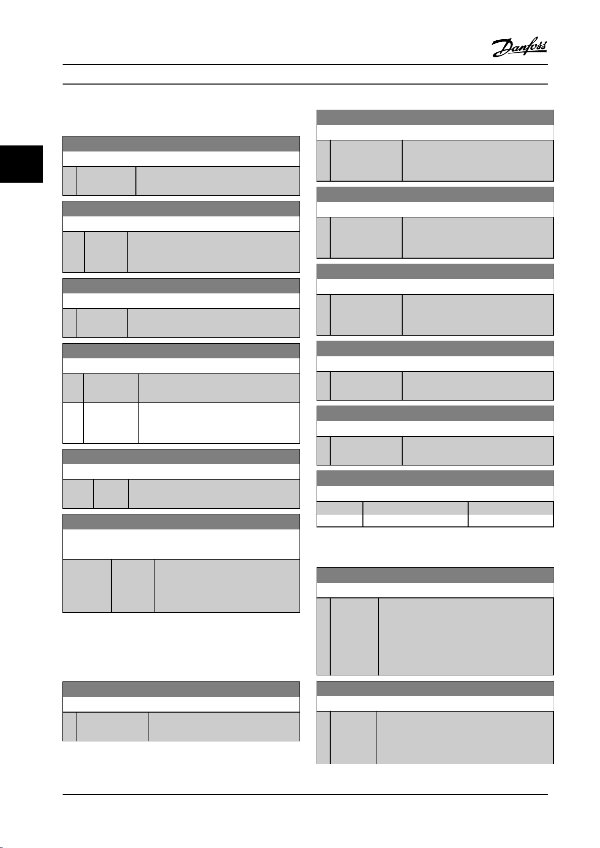
Parameters
VLT® HVAC Basic Drive FC 101
3.8.5 8-7* BACnet
8-81 Bus Error Count
Range: Function:
8-70 BACnet Device Instance
Range: Function:
33
1* [0 - 4194303 ] Enter a unique ID number for the BACnet
device.
0* [0 - 4294967295 ] This parameter shows the number of
telegrams with faults (for example, CRC
fault), detected on the bus.
8-82 Slave Messages Rcvd
8-72 MS/TP Max Masters
Range: Function:
127* [0 - 127 ] Dene the address of the master, which holds
the highest address in this network. Decreasing
this value optimizes polling for the token.
Range: Function:
0* [0 - 4294967295 ] This parameter shows the number of
valid telegrams addressed to the slave,
sent by the frequency converter.
8-83 Slave Error Count
8-73 MS/TP Max Info Frames
Range: Function:
1* [1 - 65534 ] Dene how many info/data frames the device
is allowed to send while holding the token.
8-74 "I am" Service
Option: Function:
[0] * Send at
power-up
[1] Continuously Select when the device should send the I-
Select when the device should send the I-
Am service message only at power-up.
Am service message continuously with an
interval of approximately 1 minute.
8-75 Intialisation Password
Range: Function:
admin* [1 - 1 ] Enter the password needed for execution of
Drive Re-initialization from BACnet.
8-79 Protocol Firmware version
Array[5]
Range: Function:
Size
related*
[0 - 655 ] Firmware revision of frequency
converter is in index 0, Modbus is in
index 1, Metasys N2 is in index 2, FLN
is in index 3, BACnet is in index 4.
3.8.6 8-8* FC Port Diagnostics
These parameters are used for monitoring the bus
communication via the FC port.
Range: Function:
0* [0 - 4294967295 ] This parameter shows the number of
error telegrams, which the frequency
converter could not execute.
8-84 Slave Messages Sent
Range: Function:
0* [0 - 4294967295 ] This parameter shows the number of
messages sent from the slave.
8-85 Slave Timeout Errors
Range: Function:
0* [0 - 4294967295 ] This parameter shows the number of
slave timeout errors.
8-88 Reset FC port Diagnostics
Option: Function:
[0] * Do not reset
[1] Reset counter
3.8.7 8-9* Bus Feedback
8-94 Bus Feedback 1
Range: Function:
0* [-32768 -
32767 ]
Write feedback to this parameter via the serial
communication port. Select this parameter in
parameter 20-00 Feedback 1 Source or
parameter 20-03 Feedback 2 Source as a feedback
source. Hex value 4000 h corresponds to 100%
feedback/range is ±200%.
8-80 Bus Message Count
Range: Function:
0* [0 - 4294967295 ] This parameter shows the number of
valid telegrams detected on the bus.
68 Danfoss A/S © 05/2018 All rights reserved. MG18B522
8-95 Bus Feedback 2
Range: Function:
0* [-32768 -
32767 ]
Write a feedback to this parameter via the serial
communication port. This parameter must be
selected in parameter 20-00 Feedback 1 Source or
parameter 20-03 Feedback 2 Source as a feedback
Page 71

Parameters Programming Guide
8-95 Bus Feedback 2
Range: Function:
source. The hexadecimal value 4000 h
corresponds to ±200% in 100% feedback/range.
3 3
MG18B522 Danfoss A/S © 05/2018 All rights reserved. 69
Page 72

Parameters
VLT® HVAC Basic Drive FC 101
3.9 Main Menu - Smart Logic - Group 13
3.9.1 13-** Prog. Features
3.9.2 13-0* SLC Settings
To activate, deactivate, and reset the smart logic control
sequence, use the SLC settings. The logic functions and
33
Smart logic control (SLC) is a sequence of user-dened
actions (see parameter 13-52 SL Controller Action [x])
executed by the SLC when the SLC evaluates the
associated user-dened event (see parameter 13-51 SL
Controller Event [x]) as true. Events and actions are each
numbered and linked in pairs. This means that when [0]
event is fullled (attains the value true), [0] action is
executed. After executing this action, the conditions of [1]
event is evaluated. If it is evaluated as true, [1] action is
executed, and so on. Only 1 event is evaluated at any time.
If an event is evaluated as false, nothing happens (in the
SLC) during the current scan interval and no other events
comparators are always running in the background, which
opens for separate control of digital inputs and outputs.
13-00 SL Controller Mode
Option: Function:
To enable the smart logic control to start when a start
command is present, for example, via a digital input,
Select [1] On. To disable the smart logic control, select
[0] O.
[0] * O Disables the smart logic controller.
[1] On Enables the smart logic controller.
are evaluated. This means that when the SLC starts, it
evaluates [0] event (and only [0] event) each scan interval.
Only when [0] event is evaluated as true, the SLC executes
[0] action and starts evaluating [1] event. It is possible to
program from 1–20 events and actions. When the last
event/action has been executed, the sequence starts over
again from [0] event/[0] action.
Figure 3.13 Example with 3 Event/Actions
Starting and stopping the SLC
To start or stop the SLC, select [1] On or [2] O in
parameter 13-00 SL Controller Mode. The SLC always starts
in state 0 (where it evaluates [0] event). The SLC starts
when the start event (dened in parameter 13-01 Start
Event) is evaluated as true (if [1] On is selected in
parameter 13-00 SL Controller Mode). The SLC stops when
the stop event (parameter 13-02 Stop Event) is true.
Parameter 13-03 Reset SLC resets all SLC parameters and
starts programming from the beginning.
13-01 Start Event
Option: Function:
To activate smart logic control, select the
boolean (true or false) input.
[0] False Enters the xed value of false in the logic
rule.
[1] True Enters the xed value of true in the logic
rule.
[2] Running The motor runs.
[3] In range The motor runs within programmed
current ranges (parameter 4-50 Warning
Current Low and parameter 4-51 Warning
Current High).
[4] On reference The motor runs at reference speed.
[7] Out of current
range
[8] Below I low The motor current is lower than set in
[9] Above I high The motor current is higher than set in
[16] Thermal
warning
[17] Mains out of
range
[18] Reversing The frequency converter reverses.
[19] Warning A warning is present.
[20] Alarm (trip) An alarm is present.
[21] Alarm (trip
lock)
The motor current is outside the range set
in parameter 4-18 Current Limit.
parameter 4-50 Warning Current Low.
parameter 4-51 Warning Current High.
The thermal warning turns on when the
temperature exceeds the limit in the
motor, the frequency converter, or the
thermistor.
Mains phase loss warning or alarm, if
parameter 14-12 Function at Mains
Imbalance is not set at [2] Disabled.
A trip lock alarm is present.
70 Danfoss A/S © 05/2018 All rights reserved. MG18B522
Page 73

Parameters Programming Guide
13-01 Start Event
Option: Function:
[22] Comparator 0 Use the result of comparator 0 in the logic
rule.
[23] Comparator 1 Use the result of comparator 1 in the logic
rule.
[24] Comparator 2 Use the result of comparator 2 in the logic
rule.
[25] Comparator 3 Use the result of comparator 3 in the logic
rule.
[26] Logic rule 0 Use the result of logic rule 0 in the logic
rule.
[27] Logic rule 1 Use the result of logic rule 1 in the logic
rule.
[28] Logic rule 2 Use the result of logic rule 2 in the logic
rule.
[29] Logic rule 3 Use the result of logic rule 3 in the logic
rule.
[33] Digital input
DI18
[34] Digital input
DI19
[35] Digital input
DI27
[36] Digital input
DI29
[39]*Start
command
[40] Drive stopped This event is true if the frequency
[42] Auto Reset
Trip
[50] Comparator 4 Use the result of comparator 4 in the logic
[51] Comparator 5 Use the result of comparator 5 in the logic
[60] Logic rule 4 Use the result of logic rule 4 in the logic
[61] Logic rule 5 Use the result of logic rule 5 in the logic
[83] Broken Belt A broken-belt condition is detected.
Use the value of DI18 in the logic rule
(High = true).
Use the value of DI19 in the logic rule
(High = true).
Use the value of DI27 in the logic rule
(High = true).
Use the value of DI29 in the logic rule
(High = true).
This event is true if the frequency
converter is started (either via digital
input, eldbus, or other).
converter is stopped or coasted (either via
digital input, eldbus, or other).
This event is true if the frequency
converter is tripped (but not trip-locked)
and an automatic reset is issued.
rule.
rule.
rule.
rule.
Enable this function in
parameter 22-60 Broken Belt Function.
13-02 Stop Event
Option: Function:
Select the condition (true or false) which
deactivates the smart logic controller.
[0] False Enters the xed value of false in the logic
rule.
[1] True Enters the xed value of true in the logic
rule.
[2] Running See parameter 13-01 Start Event for further
description.
[3] In range See parameter 13-01 Start Event for further
description.
[4] On reference See parameter 13-01 Start Event for further
description.
[7] Out of current
range
[8] Below I low See parameter 13-01 Start Event for further
[9] Above I high See parameter 13-01 Start Event for further
[16] Thermal
warning
[17] Mains out of
range
[18] Reversing See parameter 13-01 Start Event for further
[19] Warning See parameter 13-01 Start Event for further
[20] Alarm (trip) See parameter 13-01 Start Event for further
[21] Alarm (trip
lock)
[22] Comparator 0 Use the result of comparator 0 in the
[23] Comparator 1 Use the result of comparator 1 in the
[24] Comparator 2 Use the result of comparator 2 in the
[25] Comparator 3 Use the result of comparator 3 in the
[26] Logic rule 0 Use the result of logic rule 0 in the logic
[27] Logic rule 1 Use the result of logic rule 1 in the logic
[28] Logic rule 2 Use the result of logic rule 2 in the logic
See parameter 13-01 Start Event for further
description.
description.
description.
See parameter 13-01 Start Event for further
description.
See parameter 13-01 Start Event for further
description.
description.
description.
description.
See parameter 13-01 Start Event for further
description.
logic rule.
logic rule.
logic rule.
logic rule.
rule.
rule.
rule.
3 3
MG18B522 Danfoss A/S © 05/2018 All rights reserved. 71
Page 74

Par. 13-11
Comparator Operator
=
TRUE longer than.
. . .
. . .
Par. 13-10
Comparator Operand
Par. 13-12
Comparator Value
130BB672.10
Parameters
VLT® HVAC Basic Drive FC 101
13-02 Stop Event
Option: Function:
[29] Logic rule 3 Use the result of logic rule 3 in the logic
rule.
13-03 Reset SLC
Option: Function:
[0] * Do not reset
SLC
Retains programmed settings in parameter
group 13-** Smart Logic.
33
[30] SL Time-out 0 Use the result of timer 0 in the logic rule.
[31] SL Time-out 1 Use the result of timer 1 in the logic rule.
[32] SL Time-out 2 Use the result of timer 2 in the logic rule.
[33] Digital input
DI18
[34] Digital input
DI19
[35] Digital input
DI27
[36] Digital input
DI29
[39] Start command This event is true if the frequency
[40]*Drive stopped This event is true if the frequency
[42] Auto Reset Trip This event is true if the frequency
[50] Comparator 4 Use the result of comparator 4 in the
[51] Comparator 5 Use the result of comparator 5 in the
[60] Logic rule 4 Use the result of logic rule 4 in the logic
[61] Logic rule 5 Use the result of logic rule 5 in the logic
[70] SL Time-out 3 Use the result of timer 3 in the logic rule.
[71] SL Time-out 4 Use the result of timer 4 in the logic rule.
[72] SL Time-out 5 Use the result of timer 5 in the logic rule.
[73] SL Time-out 6 Use the result of timer 6 in the logic rule.
[74] SL Time-out 7 Use the result of timer 7 in the logic rule.
[83] Broken Belt A broken-belt condition has been
Use the value of DI18 in the logic rule
(High = true).
Use the value of DI19 in the logic rule
(High = true).
Use the value of DI27 in the logic rule
(High = true).
Use the value of DI29 in the logic rule
(High = true).
converter is started by any means (either
via digital input, eldbus, or other).
converter is stopped or coasted by any
means (either via digital input, eldbus,
or other).
converter is tripped (but not trip-locked)
and an automatic reset is issued.
logic rule.
logic rule.
rule.
rule.
detected. Enable this function in
parameter 22-60 Broken Belt Function.
[1] Reset SLC Resets all parameters in parameter group
13-** Smart Logic to default settings.
3.9.3 13-1* Comparators
Comparators are used for comparing continuous variables
(such as output frequency, output current, and analog
input) to xed preset values.
Figure 3.14 Comparators
In addition, there are digital values that are compared to
xed time values. See the explanation in
parameter 13-10 Comparator Operand. Comparators are
evaluated once in each scan interval. Use the result (true
or false) directly. All parameters in this parameter group
are array parameters with index 0–5. Select index 0 to
program comparator 0, select index 1 to program
comparator 1, and so on.
13-10 Comparator Operand
Array [6]
Option: Function:
Select the variable to be monitored by
the comparator.
[0] * Disabled
[1] Reference
[2] Feedback
[3] Motor speed
[4] Motor Current
[6] Motor power
[7] Motor voltage
[12] Analog input AI53
[13] Analog input AI54
[20] Alarm number
[30] Counter A
[31] Counter B
72 Danfoss A/S © 05/2018 All rights reserved. MG18B522
Page 75

. . .
. . .
. . .
. . .
Par. 13-43
Logic Rule Operator 2
Par. 13-41
Logic Rule Operator 1
Par. 13-40
Logic Rule Boolean 1
Par. 13-42
Logic Rule Boolean 2
Par. 13-44
Logic Rule Boolean 3
130BB673.10
Parameters Programming Guide
3.9.4 13-2* Timers
Use the result (true or false) from timers directly to dene
an event (see parameter 13-51 SL Controller Event), or as
boolean input in a logic rule (see parameter 13-40 Logic
Rule Boolean 1, parameter 13-42 Logic Rule Boolean 2, or
parameter 13-44 Logic Rule Boolean 3). A timer is only false
when started by an action (for example [29] Start timer 1)
until the timer value entered in this parameter has elapsed.
Then it becomes true again.
All parameters in this parameter group are array
parameters with index 0–2. Select index 0 to program
timer 0, select index 1 to program timer 1, and so on.
MG18B522 Danfoss A/S © 05/2018 All rights reserved. 73
13-11 Comparator Operator
Array [6]
Option: Function:
[0] Less Than (<) Select [0] < for the result of the evaluation
to be true, when the variable selected in
parameter 13-10 Comparator Operand is
smaller than the xed value in
parameter 13-12 Comparator Value. The
result is false, if the variable selected in
parameter 13-10 Comparator Operand is
greater than the xed value in
parameter 13-12 Comparator Value.
[1]*Approx.Equal
(~)
[2] Greater Than
(>)
Select [1] ≈ for the result of the evaluation
to be true, when the variable selected in
parameter 13-10 Comparator Operand is
approximately equal to the xed value in
parameter 13-12 Comparator Value.
Select [2] > for the inverse logic of option
[0] <.
13-12 Comparator Value
Array [6]
Range: Function:
0* [-9999 -
9999 ]
Enter the trigger level for the variable that is
monitored by this comparator. This
parameter is an array parameter containing
comparator values 0–5.
13-20 SL Controller Timer
Array [8]
Range: Function:
0 s* [0 -
3600 s]
Enter the value to dene the duration of the
false output from the programmed timer. A timer
is only false if it is started by an action (see
parameter 13-52 SL Controller Action [29–31] and
parameter 13-52 SL Controller Action [70–74] Start
timer X) and until the timer value has elapsed.
Array parameters contain timers 0–7.
3.9.5 13-4* Logic Rules
Combine up to 3 boolean inputs (true/false inputs) from
timers, comparators, digital inputs, status bits, and events
using the logical operators AND, OR, and NOT. Select
boolean inputs for the calculation in parameter 13-40 Logic
Rule Boolean 1, parameter 13-42 Logic Rule Boolean 2, and
parameter 13-44 Logic Rule Boolean 3. Dene the operators
used to combine the selected inputs logically in
parameter 13-41 Logic Rule Operator 1 and
parameter 13-43 Logic Rule Operator 2.
Figure 3.15 Logic Rules
Priority of calculation
The results of parameter 13-40 Logic Rule Boolean 1,
parameter 13-41 Logic Rule Operator 1, and
parameter 13-42 Logic Rule Boolean 2 are calculated rst.
The outcome (true/false) of this calculation is combined
with the settings of parameter 13-43 Logic Rule Operator 2
and parameter 13-44 Logic Rule Boolean 3, yielding the nal
result (true/false) of the logic rule.
13-40 Logic Rule Boolean 1
Array [6]
Option: Function:
[0] * False Enters the xed value of false in the logic
rule.
[1] True Enters the xed value true in the logic
rule.
[2] Running See parameter 13-01 Start Event for further
description.
[3] In range See parameter 13-01 Start Event for further
description.
[4] On reference See parameter 13-01 Start Event for further
description.
[7] Out of current
range
[8] Below I low See parameter 13-01 Start Event for further
[9] Above I high See parameter 13-01 Start Event for further
See parameter 13-01 Start Event for further
description.
description.
description.
3 3
Page 76

Parameters
VLT® HVAC Basic Drive FC 101
13-40 Logic Rule Boolean 1
Array [6]
Option: Function:
33
[16] Thermal
warning
[17] Mains out of
range
[18] Reversing See parameter 13-01 Start Event for further
[19] Warning See parameter 13-01 Start Event for further
[20] Alarm (trip) See parameter 13-01 Start Event for further
[21] Alarm (trip lock) See parameter 13-01 Start Event for further
[22] Comparator 0 Use the result of comparator 0 in the
[23] Comparator 1 Use the result of comparator 1 in the
[24] Comparator 2 Use the result of comparator 2 in the
[25] Comparator 3 Use the result of comparator 3 in the
[26] Logic rule 0 Use the result of logic rule 0 in the logic
[27] Logic rule 1 Use the result of logic rule 1 in the logic
[28] Logic rule 2 Use the result of logic rule 2 in the logic
[29] Logic rule 3 Use the result of logic rule 3 in the logic
[30] SL Time-out 0 Use the result of timer 0 in the logic rule.
[31] SL Time-out 1 Use the result of timer 1 in the logic rule.
[32] SL Time-out 2 Use the result of timer 2 in the logic rule.
[33] Digital input
DI18
[34] Digital input
DI19
[35] Digital input
DI27
[36] Digital input
DI29
[39] Start command This logic rule is true if the frequency
See parameter 13-01 Start Event for further
description.
See parameter 13-01 Start Event for further
description.
description.
description.
description.
description.
logic rule.
logic rule.
logic rule.
logic rule.
rule.
rule.
rule.
rule.
Use the value of DI18 in the logic rule
(High = true).
Use the value of DI19 in the logic rule
(High = true).
Use the value of DI27 in the logic rule
(High = true).
Use the value of DI29 in the logic rule
(High = true).
converter is started by any means (either
via digital input, or other).
13-40 Logic Rule Boolean 1
Array [6]
Option: Function:
[40] Drive stopped This logic rule is true if the frequency
converter is stopped or coasted by any
means (either via digital input, or other).
[42] Auto Reset Trip This logic rule is true if the frequency
converter is tripped (but not trip-locked)
and an automatic reset is issued.
[50] Comparator 4 Use the result of comparator 4 in the
logic rule.
[51] Comparator 5 Use the result of comparator 5 in the
logic rule.
[60] Logic rule 4 Use the result of logic rule 4 in the logic
rule.
[61] Logic rule 5 Use the result of logic rule 5 in the logic
rule.
[70] SL Time-out 3 Use the result of timer 3 in the logic rule.
[71] SL Time-out 4 Use the result of timer 4 in the logic rule.
[72] SL Time-out 5 Use the result of timer 5 in the logic rule.
[73] SL Time-out 6 Use the result of timer 6 in the logic rule.
[74] SL Time-out 7 Use the result of timer 7 in the logic rule.
[83] Broken Belt A broken-belt condition has been
detected. Enable this function in
parameter 22-60 Broken Belt Function.
13-41 Logic Rule Operator 1
Option: Function:
[0] * Disabled
[1] AND
[2] OR
[3] AND NOT
[4] OR NOT
[5] NOT AND
[6] NOT OR
[7] NOT AND NOT
[8] NOT OR NOT
13-42 Logic Rule Boolean 2
Array [6]
Option: Function:
Select the 2nd boolean (true or false)
input for the selected logic rule.
See parameter 13-40 Logic Rule
Boolean 1 for further descriptions of
options and their functions.
[0] * False
74 Danfoss A/S © 05/2018 All rights reserved. MG18B522
Page 77

Parameters Programming Guide
13-42 Logic Rule Boolean 2
Array [6]
Option: Function:
[1] True
[2] Running
[3] In range
[4] On reference
[7] Out of current range
[8] Below I low
[9] Above I high
[16] Thermal warning
[17] Mains out of range
[18] Reversing
[19] Warning
[20] Alarm (trip)
[21] Alarm (trip lock)
[22] Comparator 0
[23] Comparator 1
[24] Comparator 2
[25] Comparator 3
[26] Logic rule 0
[27] Logic rule 1
[28] Logic rule 2
[29] Logic rule 3
[30] SL Time-out 0
[31] SL Time-out 1
[32] SL Time-out 2
[33] Digital input DI18
[34] Digital input DI19
[35] Digital input DI27
[36] Digital input DI29
[39] Start command
[40] Drive stopped
[42] Auto Reset Trip
[50] Comparator 4
[51] Comparator 5
[60] Logic rule 4
[61] Logic rule 5
[70] SL Time-out 3
[71] SL Time-out 4
[72] SL Time-out 5
[73] SL Time-out 6
[74] SL Time-out 7
[83] Broken Belt A broken-belt condition has been
detected. Enable this function in
parameter 22-60 Broken Belt Function.
13-43 Logic Rule Operator 2
Array [6]
Option: Function:
Select the 2nd logical operator to be used
on the boolean input calculated in
parameter 13-40 Logic Rule Boolean 1,
parameter 13-41 Logic Rule Operator 1,
parameter 13-42 Logic Rule Boolean 2, and
the boolean input coming from
parameter 13-42 Logic Rule Boolean 2.
[13–44] signies the boolean input of
parameter 13-44 Logic Rule Boolean 3.
[13-40/13-42] signies the boolean input
calculated in parameter 13-40 Logic Rule
Boolean 1, parameter 13-41 Logic Rule
Operator 1, and parameter 13-42 Logic Rule
Boolean 2. [0] Disabled (factory setting):
Select this option to ignore
parameter 13-44 Logic Rule Boolean 3.
[0] * Disabled
[1] AND
[2] OR
[3] AND NOT
[4] OR NOT
[5] NOT AND
[6] NOT OR
[7] NOT AND NOT
[8] NOT OR NOT
13-44 Logic Rule Boolean 3
Array [6]
Option: Function:
Select the 3rd boolean (true or false)
input for the selected logic rule.
See parameter 13-40 Logic Rule
Boolean 1 for further descriptions of
options and their functions.
[0] * False
[1] True
[2] Running
[3] In range
[4] On reference
[7] Out of current range
[8] Below I low
[9] Above I high
[16] Thermal warning
[17] Mains out of range
[18] Reversing
[19] Warning
[20] Alarm (trip)
[21] Alarm (trip lock)
3 3
MG18B522 Danfoss A/S © 05/2018 All rights reserved. 75
Page 78

Parameters
VLT® HVAC Basic Drive FC 101
13-44 Logic Rule Boolean 3
Array [6]
Option: Function:
33
[22] Comparator 0
[23] Comparator 1
[24] Comparator 2
[25] Comparator 3
[26] Logic rule 0
[27] Logic rule 1
[28] Logic rule 2
[29] Logic rule 3
[30] SL Time-out 0
[31] SL Time-out 1
[32] SL Time-out 2
[33] Digital input DI18
[34] Digital input DI19
[35] Digital input DI27
[36] Digital input DI29
[39] Start command
[40] Drive stopped
[42] Auto Reset Trip
[50] Comparator 4
[51] Comparator 5
[60] Logic rule 4
[61] Logic rule 5
[70] SL Time-out 3
[71] SL Time-out 4
[72] SL Time-out 5
[73] SL Time-out 6
[74] SL Time-out 7
[83] Broken Belt
3.9.6 13-5* States
13-51 SL Controller Event
Array [20]
Option: Function:
Select the boolean input (true or
false) to dene the smart logic
controller event.
See parameter 13-02 Stop Event for
further descriptions of options and
their functions.
[0] * False
[1] True
[2] Running
[3] In range
[4] On reference
[7] Out of current range
[8] Below I low
13-51 SL Controller Event
Array [20]
Option: Function:
[9] Above I high
[16] Thermal warning
[17] Mains out of range
[18] Reversing
[19] Warning
[20] Alarm (trip)
[21] Alarm (trip lock)
[22] Comparator 0
[23] Comparator 1
[24] Comparator 2
[25] Comparator 3
[26] Logic rule 0
[27] Logic rule 1
[28] Logic rule 2
[29] Logic rule 3
[30] SL Time-out 0
[31] SL Time-out 1
[32] SL Time-out 2
[33] Digital input DI18
[34] Digital input DI19
[35] Digital input DI27
[36] Digital input DI29
[39] Start command
[40] Drive stopped
[42] Auto Reset Trip
[50] Comparator 4
[51] Comparator 5
[60] Logic rule 4
[61] Logic rule 5
[70] SL Time-out 3
[71] SL Time-out 4
[72] SL Time-out 5
[73] SL Time-out 6
[74] SL Time-out 7
[83] Broken Belt
13-52 SL Controller Action
Array [20]
Option: Function:
Select the action corresponding to the
SLC event. Actions are executed when
the corresponding event (dened in
parameter 13-51 SL Controller Event) is
evaluated as true. The following actions
are available for selection:
[100] ResetAlarm
[0] * Disabled
[1] No action
76 Danfoss A/S © 05/2018 All rights reserved. MG18B522
Page 79

Parameters Programming Guide
13-52 SL Controller Action
Array [20]
Option: Function:
[2] Select set-up 1 Changes the active set-up
(parameter 0-10 Active Set-up) to set-up
1.
[3] Select set-up 2 Changes the active set-up
(parameter 0-10 Active Set-up) to set-up
2.
[10] Select preset ref0Selects preset reference 0.
[11] Select preset ref1Selects preset reference 1.
[12] Select preset ref2Selects preset reference 2.
[13] Select preset ref3Selects preset reference 3.
[14] Select preset ref4Selects preset reference 4.
[15] Select preset ref5Selects preset reference 5.
[16] Select preset ref6Selects preset reference 6.
[17] Select preset ref7Selects preset reference 7. If the active
preset reference is changed, it merges
with other preset reference commands
coming from either the digital inputs or
via a eldbus.
[18] Select ramp 1 Selects ramp 1.
[19] Select ramp 2 Selects ramp 2.
[22] Run Issues a start command to the
frequency converter.
[23] Run reverse Issues a start reverse command to the
frequency converter.
[24] Stop Issues a stop command to the
frequency converter.
[25] Qstop Issues a quick stop command to the
frequency converter.
[26] DC Brake Issues a DC stop command to the
frequency converter.
[27] Coast The frequency converter coasts
immediately. All stop commands
including the coast command stop the
SLC.
[28] Freeze output Freezes the output frequency of the
frequency converter.
[29] Start timer 0 Starts timer 0, see parameter 13-20 SL
Controller Timer for further description.
[30] Start timer 1 Starts timer 1, see parameter 13-20 SL
Controller Timer for further description.
[31] Start timer 2 Starts timer 2, see parameter 13-20 SL
Controller Timer for further description.
13-52 SL Controller Action
Array [20]
Option: Function:
[32] Set digital out A
low
[33] Set digital out B
low
[34] Set digital out C
low
[35] Set digital out D
low
[38] Set digital out A
high
[39] Set digital out B
high
[40] Set digital out C
high
[41] Set digital out D
high
[60] Reset Counter A Resets counter A to 0.
[61] Reset Counter B Resets counter B to 0.
[70] Start Timer 3 Starts timer 3, see parameter 13-20 SL
[71] Start Timer 4 Starts timer 4, see parameter 13-20 SL
[72] Start Timer 5 Starts timer 5, see parameter 13-20 SL
[73] Start Timer 6 Starts timer 6, see parameter 13-20 SL
[74] Start Timer 7 Starts timer 7, see parameter 13-20 SL
[100] Reset Alarm Reset the alarm.
Any output with digital output 1
selected is low (o).
Any output with digital output 2
selected is low (o).
Any output with digital output 3
selected is low (o).
Any output with digital output 4
selected is low (o).
Any output with digital output 1
selected is high (closed).
Any output with digital output 2
selected is high (closed).
Any output with digital output 3
selected is high (closed).
Any output with digital output 4
selected is high (closed).
Controller Timer for further description.
Controller Timer for further description.
Controller Timer for further description.
Controller Timer for further description.
Controller Timer for further description.
3 3
MG18B522 Danfoss A/S © 05/2018 All rights reserved. 77
Page 80

Parameters
VLT® HVAC Basic Drive FC 101
3.10 Main Menu - Special Functions - Group
14
3.10.1 14-0* Inverter Switching
14-03 Overmodulation
Option: Function:
(from 0% at nominal speed rising to approximately
12% at double nominal speed).
33
14-01 Switching Frequency
Option: Function:
Select the inverter switching frequency. Changing
the switching frequency can help to reduce
acoustic noise from the motor.
NOTICE!
The output frequency value of the
frequency converter must never exceed
1/10 of the switching frequency. When the
motor runs, adjust the switching frequency
in parameter 14-01 Switching Frequency
until the motor is as quiet as possible.
NOTICE!
High switching frequencies increase heat
generation in the frequency converter and
may reduce its lifetime.
NOTICE!
Not all options are available in all power
sizes.
[0] Ran3 3 kHz true random PWM (white noise
modulation).
[1] Ran5 5 kHz true random PWM (white noise
modulation).
[2] 2.0 kHz
[3] 3.0 kHz
[4] 4.0 kHz
[5] 5.0 kHz
[6] 6.0 kHz
[7] 8.0 kHz
[8] 10.0 kHz
[9] 12.0 kHz
[10] 16.0 kHz
14-03 Overmodulation
Option: Function:
[0] * O Selects no overmodulation of the output voltage to
avoid torque ripple on the motor shaft.
[1] On The overmodulation function generates an extra
voltage of up to 8% of U
overmodulation, which results in an extra torque of
10–12% in the middle of the over-synchronous range
output voltage without
max
14-07 Dead Time Compensation Level
Range: Function:
Size
related*
[0 -
100 ]
Level of applied dead time compensation
in percentage. A high level (>90%)
optimizes the dynamic motor response. A
level 50–90% is suitable for both motor-
torque-ripple minimization and motor
dynamics. A 0 level turns o the dead
time compensation.
14-08 Damping Gain Factor
Range: Function:
Size related* [0 -
100 %]
Set the damping factor for DC-link
voltage compensation. See
parameter 14-51 DC-Link Voltage
Compensation.
14-09 Dead Time Bias Current Level
Range: Function:
Size related* [0 - 100 %] To add to the current-sense signal for
dead time compensation for some
motors, set a bias signal (in
percentage).
3.10.2 14-1* Mains On/O
Parameters for conguring mains failure monitoring and
handling.
14-10 Mains Failure
Congure the action of the frequency converter when the mains
voltage is below the mains voltage limit congured in
parameter 14-11 Mains Fault Voltage Level.
Option: Function:
[0] * No function
[1] Ctrl. ramp-down
[3] Coasting
[4] Kinetic back-up
[5] Kinetic back-up, trip
[6] Alarm
[7] Kin. back-up, trip w
recovery
78 Danfoss A/S © 05/2018 All rights reserved. MG18B522
Page 81

Parameters Programming Guide
14-11 Mains Fault Voltage Level
Range: Function:
Size
related*
[100 -
800 V]
Use this parameter to dene at which
AC voltage the function selected in
parameter 14-10 Mains Failure should
be activated.
14-12 Function at Mains Imbalance
Option: Function:
NOTICE!
Selecting this option may reduce the
lifetime of the frequency converter.
Operation under severe mains imbalance
conditions reduces the lifetime of the motor. If
the motor is operated continuously near nominal
load, conditions are considered severe.
When a severe mains imbalance is detected,
select 1 of the available functions.
[0] * Trip Trips the frequency converter.
[1] Warning Issues a warning.
[2] Disabled No action.
[3] Derate The frequency converter would derate.
14-21 Automatic Restart Time
Range: Function:
10 s* [0 - 600s]To start the automatic reset function, enter the
time interval from trip. This parameter is active
when parameter 14-20 Reset Mode is set to [1] -
[13] Automatic reset.
14-22 Operation Mode
Option: Function:
To reset all parameter values to default, select
[2] Initialisation.
[0]*Normal
operation
[2] Initiali-
sation
Select [0] Normal operation for normal
operation of the frequency converter with the
motor in the selected application.
Select [2] Initialisation to reset all parameter
values to default settings, excluding bus
communication parameters, parameter groups
15-0* Operating Data and 15-3* Alarm Log. The
frequency converter is reset during the next
power-up.
Parameter 14-22 Operation Mode also reverts to
the default setting [0] Normal operation.
3 3
3.10.3 14-2* Trip Reset
14-20 Reset Mode
Select the reset function after tripping. Once reset, the frequency
converter can be restarted.
Option: Function:
[0] * Manual reset Select [0] Manual reset to reset the
frequency converter via [Reset] or via
the digital inputs.
[1] Automatic reset x 1 Select [1]-[12] Automatic reset x 1…
x20 to perform between 1 and 20
automatic resets after tripping.
[2] Automatic reset x 2
[3] Automatic reset x 3
[4] Automatic reset x 4
[5] Automatic reset x 5
[6] Automatic reset x 6
[7] Automatic reset x 7
[8] Automatic reset x 8
[9] Automatic reset x 9
[10] Automatic reset x 10
[11] Automatic reset x 15
[12] Automatic reset x 20
[13] Innite auto reset Select [13] Innite Automatic Reset for
continuous resetting after tripping.
14-27 Action At Inverter Fault
Select how the frequency converter acts in the case of
overvoltage, overcurrent, short circuit, or grounding errors.
Option: Function:
[0] Trip
[1] * Warning
14-29 Service Code
Range: Function:
0* [0 - 0x7FFFFFFF ] Service use only.
3.10.4 14-3* Current Limit Control
Parameters for conguring the current limit controller,
which is activated when the motor current exceeds the
preset current limits (see parameter 4-18 Current Limit).
These parameters are used to reduce torque as quickly as
possible without losing control of the motor.
14-30 Current Lim Ctrl, Proportional Gain
Range: Function:
100 %* [0 - 500 %] Enter the proportional gain value for the
current limit controller. A higher value
makes the controller react faster. Excessive
value setting leads to controller instability.
MG18B522 Danfoss A/S © 05/2018 All rights reserved. 79
Page 82

Parameters
VLT® HVAC Basic Drive FC 101
14-31 Current Lim Ctrl, Integration Time
3.10.6 14-5* Environment
Range: Function:
0.020 s* [0.002 - 2 s] Control the current limit control
33
integration time. Setting it to a lower
value makes it react faster. A setting too
low leads to control instability.
14-32 Current Lim Ctrl, Filter Time
Range: Function:
5 ms* [1 - 100 ms] Set a time constant for the current limit
controller low-pass lter.
3.10.5 14-4* Energy Optimization
Parameters for adjusting the energy optimization level in
both variable torque (VT) and automatic energy optimization (AEO) mode.
Automatic energy optimization is only active if
parameter 1-03 Torque Characteristics is set to [3] Auto
Energy Optim.
14-40 VT Level
Range: Function:
90 %* [40 -
90 %]
14-41 AEO Minimum Magnetisation
Range: Function:
66 %* [40 - 75 %] Enter the minimum allowable magnetization
14-44 d-axis current optimization for IPM
Range: Function:
100 %* [0 - 200 %]
NOTICE!
This parameter cannot be adjusted
while the motor is running.
Enter the level of motor magnetization at low
speed. Low values reduce energy loss in the
motor, but also reduce load capability.
for AEO. Low values reduce energy loss in
the motor, but also reduce resistance to
sudden load changes.
These parameters help the frequency converter to operate
under special environmental conditions.
14-50 RFI Filter
This parameter is only valid for frequency converters of the
following enclosure sizes:
IP20, 3x200–240 V, enclosure sizes H6–H8
•
IP20, 3x380–480 V, enclosure sizes H6–H8
•
IP54, 3x380–480 V, enclosure sizes I6–I8
•
IP20, 3x525–600 V, enclosure sizes H6–H10
•
Option: Function:
[0] O Select [0] O only if the frequency converter is fed by
an isolated mains source (IT mains).
In this mode, the internal RFI lter capacitors between
chassis and the mains RFI lter circuit are cut out to
reduce the ground capacity currents.
[1] * On Select [1] On to ensure that the frequency converter
complies with EMC standards.
14-51 DC-Link Voltage Compensation
Option: Function:
[0] O The overmodulation for output voltage is o to avoid
torque ripple on the motor shaft.
[1] * On Enables the overmodulation for output voltage to
obtain an output voltage up to 15% greater than the
mains voltage.
14-52 Fan Control
This parameter is used to select the fan control operating mode.
The acoustic noise of the frequency converter is dierent from
running heavy load (high heat sink temperature) to running light
load or stand-by mode.
Option: Function:
[0] Auto The fan runs with full speed for a short
time and then automatically adjusts the
speed according to the load and ambient
temperature. The fan also runs at minimum
speed even if the reference is 0 Hz due to
the heat generated from the IGBT. The fan
stops if sleep mode function is activated.
This is the default setting for all frequency
converters except H1 enclosure sizes.
[4] Auto Low Temp
Env.
[5] Constant-on
mode
[6] Constant-o
mode
Only valid for H6-H10 & I6-I8 enclosure
sizes.
For on-site fan test or if the fan must run
100% speed constantly. Only valid for H1-
H5 & I2-I4 enclosure sizes.
If convection cooling is sucient or the
frequency converter is mounted in a
80 Danfoss A/S © 05/2018 All rights reserved. MG18B522
Page 83

Parameters Programming Guide
14-52 Fan Control
This parameter is used to select the fan control operating mode.
The acoustic noise of the frequency converter is dierent from
running heavy load (high heat sink temperature) to running light
load or stand-by mode.
Option: Function:
demonstration panel, exhibitions and so on.
The frequency converter trips on heat sink
overtemperature if loaded more than the
convection cooling allows. Only valid for
H1-H5 & I2-I4 enclosure sizes.
[7] On-when-
Inverter-is-on-
else-o Mode
The fan runs at maximum speed if in hand-
on mode or reference is above 0 Hz. The
fan is stopped if sleep mode is active. This
is the default setting for H1 enclosure size
only but can also be selected for H2-H5 &
I2-I4 enclosure sizes.
14-53 Fan Monitor
Select which reaction the frequency converter should take in
case a fan fault is detected. This parameter is only valid for
frequency converters of the following enclosure sizes:
IP20, 3x200–240 V, enclosure sizes H6–H8.
•
IP20, 3x380–480 V, enclosure sizes H6–H8.
•
IP54, 3x380–480 V, enclosure sizes I6–I8.
•
IP20, 3x525–600 V, enclosure sizes H6–H10.
•
Option: Function:
[0] Disabled
[1] * Warning
[2] Trip
14-55 Output Filter
Select whether an output lter is present.
Option: Function:
[0] * No Filter
[1] Sine-Wave Filter
[3] Sine-Wave Filter
with Feedback
[4] dv/dt This option in only valid for the
frequency converter of the following
enclosure sizes:
IP20, 3x200-240 V, enclosure
•
sizes H6-H8
IP20, 3x380-480 V, enclosure
•
sizes H6-H8
IP54, 3x380-480 V, enclosure
•
sizes I6-I8
IP20, 3x525-600 V, enclosure
•
sizes H6-H10
3.10.7 14-6* Auto Derate
Parameter group for conguring automatic derating based
on the output frequency of the frequency converter.
14-63 Min Switch Frequency
Set the minimum switching frequency allowed by the output
lter.
Option: Function:
[2] * 2.0 kHz
[3] 3.0 kHz
[4] 4.0 kHz
[5] 5.0 kHz
[6] 6.0 kHz
[7] 8.0 kHz
[8] 10.0 kHz
[9] 12.0 kHz
[10] 16.0 kHz
14-64 Dead Time Compensation Zero Current Level
If a long motor cable is used, set the parameter to [0] Disabled to
minimize the motor-torque ripple.
Option: Function:
[0] * Disabled
[1] Enabled
14-65 Speed Derate Dead Time Compensation
Range: Function:
Size
related*
[ 20 -
1000 Hz]
Dead time compensation level is reduced
linearly from the maximum level of the
output frequency set in
parameter 14-07 Dead Time Compensation
Level to the minimum level of the output
frequency set in this parameter.
3 3
MG18B522 Danfoss A/S © 05/2018 All rights reserved. 81
Page 84

Parameters
VLT® HVAC Basic Drive FC 101
3.10.8 14-9* Fault Settings
The parameter group for fault customization settings.
33
14-90 Fault Level
Use this parameter to customize fault levels. Only index 7, which
indicates overcurrent faults, is supported.
Option: Function:
[3] * Trip lock Alarm is set to trip lock level.
[4] Trip w.
delayed reset
[5] Flystart The frequency converter tries to catch a
Alarm is congured into trip alarm, which
can be reset after a delay time. For
example, if overcurrent alarm is congured
to this option, it can be reset 3 minutes
after the alarm is reported.
motor spinning when starting. If this option
is selected, parameter 1-73 Flying Start s set
to [1] Enabled.
82 Danfoss A/S © 05/2018 All rights reserved. MG18B522
Page 85

Parameters Programming Guide
3.11 Main Menu - Drive Information - Group
15
Parameter group containing frequency converter
information such as operating data, hardware congu-
ration, and software versions.
3.11.1 15-0* Operating Data
15-00 Operating hours
Range: Function:
0 h* [0 - 0x7f. h] View how many hours the frequency
converter has run. The value is saved
when the frequency converter is turned
o.
15-01 Running Hours
Range: Function:
0 h* [0 -
0x7f. h]
15-02 kWh Counter
Range: Function:
0 kWh* [0 - 65535
kWh]
15-03 Power Up's
Range: Function:
0* [0 - 2147483647 ] View the number of times the frequency
View how many hours the motor has run.
Reset the counter in parameter 15-07 Reset
Running Hours Counter. The value is saved
when the frequency converter is turned o.
View the output power of the frequency
converter in kWh as a mean value over 1
hour. Reset the counter in
parameter 15-06 Reset kWh Counter.
converter has been powered up.
15-06 Reset kWh Counter
Option: Function:
[1] Reset counter To reset the kWh counter to 0, select [1]
Reset and press [OK] (see
parameter 15-02 kWh Counter).
15-07 Reset Running Hours Counter
Option: Function:
[0] * Do not reset
[1] Reset counter To reset the running hours counter, select [1]
Reset counter and press [OK]
(parameter 15-01 Running Hours) to 0 (see
also parameter 15-01 Running Hours).
3.11.2 15-3* Alarm Log
Parameters in this group are array parameters, where up to
10 fault logs can be viewed. [0] is the most recent logged
data, and [9] the oldest. Fault codes, values, and time
stamp can be viewed for all logged data.
15-30 Alarm Log: Error Code
Range: Function:
0* [0 - 255 ] View the fault code and lookup its meaning in
chapter 4 Troubleshooting.
15-31 InternalFaultReason
Range: Function:
0* [-32767 - 32767 ] View a description of the error. This
parameter is used with alarm 38, Internal
Fault.
3.11.3 15-4* Drive Identication
3 3
15-04 Over Temp's
Range: Function:
0* [0 - 65535 ] View the number of frequency converter
temperature faults that have occurred.
Parameters containing read-only information about the
hardware and software conguration of the frequency
converter.
15-40 FC Type
Range: Function:
15-05 Over Volt's
Range: Function:
0* [0 - 65535 ] View the number of frequency converter
overvoltages that have occurred.
0* [0 - 6 ] View the FC type code. The readout is identical to
the frequency converter series power eld of the
type code denition, characters 1–6.
15-41 Power Section
15-06 Reset kWh Counter
Option: Function:
NOTICE!
To reset, press [OK].
[0] * Do not reset
MG18B522 Danfoss A/S © 05/2018 All rights reserved. 83
Range: Function:
0* [0 - 20 ] View the FC type code. The readout is identical to
the frequency converter series power eld of the
type code denition, characters 7–10.
Page 86

Parameters
VLT® HVAC Basic Drive FC 101
15-42 Voltage
Range: Function:
0* [0 - 20 ] View the FC type code. The readout is identical to
33
the frequency converter series power eld of the
type code denition, characters 11–12.
3.12 Main Menu - Data Readouts - Group 16
3.12.1 16-0* General Status
16-00 Control Word
Range: Function:
15-43 Software Version
Range: Function:
0* [0 - 0 ] View the software version of the frequency
converter.
15-44 Ordered TypeCode
Range: Function:
0* [0 - 40 ] View the type code string used for reordering the
frequency converter in its original conguration.
15-45 Actual Typecode String
Range: Function:
0 [0 - 40 ] View the actual type code string.
15-46 Drive Ordering No
Range: Function:
0* [0 - 8 ] View the 8-digit ordering number for reordering
the frequency converter in its original congu-
ration.
15-48 LCP Id No
Range: Function:
0* [0 - 0 ] View the LCP ID number.
0* [0 - 65535 ] View the control word sent from the frequency
converter via the serial communication port in
hex code.
Bit Bit = 0 Bit = 1
00 Preset reference option lsb –
01
Preset reference option 2nd bit of
preset references
02 DC brake Ramp
03 Coasting Enable
04 Quick stop Ramp
05 Freeze output Ramp
06 Ramp stop Start
07 No function Reset
08 No function Jog
09 Ramp 1 Ramp 2
10 Data not valid Valid
11 Relay_A not active Relay_A activated
12 Relay_B not active Relay_B activated
13 Choice of set-up lsb –
14 No function No function
15 No function Reversing
Table 3.6 Control Word
–
15-49 SW ID Control Card
Range: Function:
0* [0 - 0 ] View the control card software version number.
15-50 SW ID Power Card
Range: Function:
0* [0 - 0 ] View the power card software version number.
15-51 Drive Serial Number
16-01 Reference [Unit]
Range: Function:
0 ReferenceFeed-
backUnit*
[-4999 - 4999
ReferenceFeed-
backUnit]
View the present reference
value applied on impulse
or analog basis in the unit
resulting from the congu-
ration selected in
parameter 1-00 Congu-
ration Mode (Hz).
Range: Function:
0* [0 - 10 ] View the frequency converter serial number.
15-53 Power Card Serial Number
Range: Function:
0* [0 - 0 ] View the power card serial number.
16-02 Reference [%]
Range: Function:
0 %* [-200 - 200 %] View the total reference. The total
reference is the sum of digital, analog,
preset, bus, and freeze references.
15-59 Filename
Range: Function:
0 [0 - 16 ] View the current CSIV le name.
84 Danfoss A/S © 05/2018 All rights reserved. MG18B522
Page 87

Parameters Programming Guide
16-03 Status Word
Range: Function:
0* [0 - 65535 ] View the status word sent from the frequency
converter via the serial communication port in
hex code.
Bit Bit = 0 Bit = 1
00 Control not ready Ready
01 VLT not ready Ready
02 Coasting Enable
03 No fault Trip
04 No warning Warning
05 Reserved –
06 No trip lock Trip lock
07 No warning Warning
08
Speed ≠ ref.
09 Local control Bus control
10 Out of range Frequency OK
11 Not running Running
12 No function No function
13 Voltage OK Above limit
14 Current OK Above limit
15 Thermal-level OK Above limit
Table 3.7 Status Word
Speed = ref.
16-05 Main Actual Value [%]
Range: Function:
0 %* [-200 - 200 %] View the 2 byte word sent with the status
word to the bus master reporting the
main actual value.
16-09 Custom Readout
Range: Function:
0 CustomRea-
doutUnit*
[0 - 9999
CustomRea-
doutUnit]
View the user-dened readouts
as dened in
parameter 0-30 Custom Readout
Unit, parameter 0-31 Custom
Readout Min Value, and
parameter 0-32 Custom Readout
Max Value.
3.12.2 16-1* Motor Status
16-10 Power [kW]
Range: Function:
0 kW* [0 - 1000
kW]
Displays the actual motor power in kW.
The value shown is calculated on the basis
of the actual motor voltage and motor
current.
16-11 Power [hp]
Range: Function:
0 hp* [0 - 1000
hp]
View the actual motor power in hp. The
value shown is calculated based on the
actual motor voltage and motor current.
16-12 Motor Voltage
Range: Function:
0 V* [0 - 65535 V] View the motor voltage, a calculated value
used for controlling the motor.
16-13 Frequency
Range: Function:
0 Hz* [0 - 6553.5 Hz] View the motor frequency, without
resonance damping.
16-14 Motor current
Range: Function:
0 A* [0 - 655.35 A] View the motor current measured as an
average value, I
RMS
.
16-15 Frequency [%]
Range: Function:
0 %* [0 -
6553.5 %]
View a 2-byte word reporting the actual
motor frequency (without resonance
damping) as a percentage (scale 0000–4000
hex) of parameter 4-19 Max Output
Frequency.
16-16 Torque [Nm]
Range: Function:
0 Nm* [-30000 -
30000 Nm]
View the torque value that is applied on
the motor shaft. Some motors supply more
than 160% torque. Consequently, the
minimum value and the maximum value
depend on the minimum/maximum motor
current as well as the motor used.
16-17 Speed [RPM]
Range: Function:
0 RPM* [-30000 -
30000 RPM]
View the actual motor RPM. The motor
RPM is estimated in open-loop process or
closed-loop process control modes and
the motor RPM is measured in speed
closed-loop mode.
16-18 Motor Thermal
Range: Function:
0 %* [0 -
100 %]
View the calculated motor temperature in
percentage of allowed maximum. At 100%, a trip
occurs if selected in parameter 1-90 Motor
3 3
MG18B522 Danfoss A/S © 05/2018 All rights reserved. 85
Page 88

Parameters
VLT® HVAC Basic Drive FC 101
16-18 Motor Thermal
3.12.4 16-5* Ref. & Feedb.
Range: Function:
Thermal Protection. The basis for the calculation
33
is the ETR function selected in
parameter 1-90 Motor Thermal Protection.
16-22 Torque [%]
16-50 External Reference
Range: Function:
0 %* [-200 - 200 %] View the total reference, the sum of
digital, analog, preset, bus, and freeze
references.
Range: Function:
0 %* [-200 -
200 %]
View the torque in percentage (in relation
to the nominal torque) that is applied to
the motor shaft.
3.12.3 16-3* Drive Status
16-30 DC Link Voltage
16-52 Feedback[Unit]
Range: Function:
0
ProcessCtrlUnit*
[-4999 - 4999
ProcessCtrlUnit]
View the feedback resulting
from the selection of scaling
in parameter 3-02 Minimum
Reference and
parameter 3-03 Maximum
Reference.
Range: Function:
0 V* [0 - 65535 V ] Shows the actual DC-link voltage.
16-54 Feedback 1 [Unit]
Range: Function:
16-34 Heatsink Temp.
Range: Function:
0 °C* [-128 - 127 °C] View the heat sink temperature of the
frequency converter.
16-35 Inverter Thermal
Range: Function:
0 %* [0 - 255 %] View the percentage of thermal load on the
frequency converter. At 100%, a trip occurs.
0
ProcessCtrlUnit*
[-999999.999 -
999999.999
ProcessCtrlUnit]
16-55 Feedback 2 [Unit]
View the feedback 1 value
resulting from the selection
of scaling in
parameter 3-02 Minimum
Reference and
parameter 3-03 Maximum
Reference.
Range: Function:
16-36 Inv. Nom. Current
Range: Function:
0 A* [0 - 655.35 A] View the inverter nominal current. The data
is used for motor overload protection and
so on.
16-37 Inv. Max. Current
0
ProcessCtrlUnit*
[-999999.999 -
999999.999
ProcessCtrlUnit]
View the feedback 2 value
resulting from the selection
of scaling in
parameter 3-02 Minimum
Reference and
parameter 3-03 Maximum
Reference.
Range: Function:
0 A* [0 - 655.35 A] View the inverter maximum current. The
data is used for calculation of frequency
converter protection and so on.
16-38 SL Controller State
Range: Function:
0* [0 - 20 ] View the actual state of the smart logic controller
(SLC).
86 Danfoss A/S © 05/2018 All rights reserved. MG18B522
Page 89

Parameters Programming Guide
3.12.5 16-6* Inputs and Outputs
16-60 Digital Input
Range: Function:
0* [0 -
4095 ]
16-61 Terminal 53 Setting
Option: Function:
View actual state of the digital inputs 18, 19, 27,
and 29.
Bit 0 Unused
Bit 1 Unused
Bit 2 Digital input terminal 29
Bit 3 Digital input terminal 27
Bit 4 Digital input terminal 19
Bit 5 Digital input terminal 18
Bit 6–15 Unused
Table 3.8 Bits Denition
View the setting of input terminal 53.
Current = 0
•
Voltage = 1
•
16-66 Digital Output
Range: Function:
0* [0 -
15 ]
View the binary value of all digital outputs.
Denition:
X: Not used
0: Low
1: High
XX None used
X0 Terminal 42 not used, terminal 45
X1 Terminal 42 not used, terminal 45
0X Terminal 42 low, terminal 45 not
0 Terminal 42 low, terminal 45 low.
1 Terminal 42 low, terminal 45 high.
1X Terminal 42 high, terminal 45 not
10 Terminal 42 high, terminal 45 low.
11 Terminal 42 high, terminal 45 high.
Table 3.9 Binary Value of Digital Outputs
3 3
low.
high.
used.
used.
[0] * Current mode
[1] Voltage mode
16-62 Analog input 53
Range: Function:
1* [0 - 20 ] View the actual value at input 53.
16-63 Terminal 54 Setting
View the setting of input terminal 54.
Current = 0
•
Voltage = 1
•
Option: Function:
[0] * Current mode
[1] Voltage mode
16-64 Analog input 54
Range: Function:
1* [0 - 20 ] View the actual value at input 54.
16-65 Analog output 42 [mA]
Range: Function:
0 mA* [0 - 20
mA]
View the actual value at output 42 in mA.
The value shown reects the selection in
parameter 6–90 Terminal 42 Mode and
parameter 6-91 Terminal 42 Analog Output.
16-67 Pulse Input #29 [Hz]
Range: Function:
0* [0 - 130000 ] View the actual frequency rate on terminal 29.
16-71 Relay output
Range: Function:
0* [0 - 31 ] View the setting of the relay.
Bit 0~2 Unused
Bit 3 Relay 02
Bit 4 Relay 01
Bit 5~15 Unused
Table 3.10 Bits Denition
16-72 Counter A
Range: Function:
0* [-32768 -
32767 ]
View the present value of counter A. Counters are
useful as comparator operands, see
parameter 13-10 Comparator Operand.
The value can be reset or changed either via
digital inputs (parameter group 5-1* Digital Inputs)
or by using an SLC action (parameter 13-52 SL
Controller Action).
MG18B522 Danfoss A/S © 05/2018 All rights reserved. 87
Page 90

Parameters
VLT® HVAC Basic Drive FC 101
16-73 Counter B
Range: Function:
0* [-32768 -
32767 ]
33
View the present value of counter B. Counters are
useful as comparator operands
(parameter 13-10 Comparator Operand).
The value can be reset or changed either via
digital inputs (parameter group 5-1* Digital Inputs)
or by using an SLC action (parameter 13-52 SL
Controller Action).
16-79 Analog output 45 [mA]
16-94 Ext. Status Word
Range: Function:
0* [0 - 0xFFFFFFFFUL ] Shows the extended status word sent
via the serial communication port in
hex code.
16-95 Ext. Status Word 2
Range: Function:
0* [0 - 0xFFFFFFFFUL ] Shows the extended status word 2 sent
via the serial communication port in
hex code.
Range: Function:
0 mA* [0 - 20
mA]
View the actual value at output 45 in mA.
The value shown reects the selection in
parameter 6-70 Terminal 45 Mode and
parameter 6-71 Terminal 45 Analog Output.
3.12.6 16-8* Fieldbus & FC Port
Parameters for reporting the bus references and control
words.
16-86 FC Port REF 1
Range: Function:
0* [-32768 - 32767 ] View the last received reference from the
FC port.
16-97 Alarm Word 3
Range: Function:
0* [0 - 4294967295] View the alarm word 3 sent via the serial
communication port in hex code.
16-98 Warning Word 3
Range: Function:
0* [0 - 4294967295] View the warning word 3 sent via the
serial communication port in hex code.
3.13 Main Menu - Data Readouts 2 - Group
18
Parameters in this group are array parameters, where up to
10 fault logs can be viewed. [0] is the most recent logged
data, and [9] is the oldest. Fault codes, values, and time
3.12.7 16-9* Diagnosis Read-Outs
stamp can be viewed for all logged data.
16-90 Alarm Word
Range: Function:
0* [0 - 0xFFFFFFFFUL ] View the alarm word sent via the serial
communication port in hex code.
16-91 Alarm Word 2
Range: Function:
0* [0 - 0xFFFFFFFFUL ] View the alarm word 2 sent via the
serial communication port in hex code.
16-92 Warning Word
Range: Function:
0* [0 - 0xFFFFFFFFUL ] View the warning word sent via the
serial communication port in hex code.
16-93 Warning Word 2
Range: Function:
0* [0 - 0xFFFFFFFFUL ] View the warning word 2 sent via the
serial communication port in hex code.
3.13.1 18-1* Fire Mode Log
18-10 FireMode Log:Event
Range: Function:
0* [0 - 255 ] View re mode event.
3.13.2 18-5* Ref. & Feedb.
18-50 Sensorless Readout [unit]
Range: Function:
0 Sensor-
lessUnit*
[-999999.999 -
999999.999
SensorlessUnit]
View the pressure or ow
resulting from the sensorless
calculations. This value is not the
value used for control. The value
is only updated if sensorless data
supports both ow and pressure.
88 Danfoss A/S © 05/2018 All rights reserved. MG18B522
Page 91

Parameters Programming Guide
3.14 Main Menu - FC Closed Loop - Group
20
This parameter group is used for conguring the closedloop PI controller that controls the output frequency of the
frequency converter.
3.14.1 20-0* Feedback
This parameter group is used to congure the feedback
signal for the closed-loop PI control of the frequency
converter.
20-00 Feedback 1 Source
Option: Function:
This parameter denes which input is
used as the source of the feedback
signal.
[0] * No function
[1] Analog Input 53
[2] Analog Input 54
[3] Pulse input 29
[100] Bus Feedback 1
[101] Bus Feedback 2
[104] Sensorless Flow
[105] Sensorless Pressure
20-01 Feedback 1 Conversion
Option: Function:
This parameter allows a conversion function to
be applied to feedback 1.
[0] * Linear [0] Linear has no eect on the feedback.
[1] Square
root
20-03 Feedback 2 Source
Option: Function:
[0] * No function
[1] Analog Input 53
[2] Analog Input 54
[3] Pulse input 29
[100] Bus Feedback 1
[101] Bus Feedback 2
[1] Square root is commonly used when a
pressure sensor is used to provide ow
feedback.
(( flow ∝ pressure)).
20-12 Reference/Feedback Unit
Option: Function:
Select the unit to be used with
references and feedbacks for closed
loop.
[0] * None Expressionlimit
[20] l/s
[23] m3/s
[24] m3/min
[25] m3/h
[71] bar
[73] kPa
[74] m Wg
[75] mm Hg
[120] GPM
[121] gal/s
[122] gal/min
[123] gal/h
[124] CFM
[125]
ft3/s
[126]
ft3/min
[170] psi
[171] lb/in2
[172] in WG
[173] ft WG
[174] in Hg
3.14.2 20-2* Feedback/Setpoint
Parameter group for feedback function and setpoints.
Select which setpoint and feedback to use. The setpoint
and feedback can be a xed pair or selected separately
based on logic comparisons.
20-20 Feedback Function
Select how the feedback should be calculated. The feedback can
be either a single feedback source or a combination of several
feedbacks.
Option: Function:
[0] Sum
[1] Dierence
[2] Average
[3] * Minimum
[4] Maximum
3 3
20-04 Feedback 2 Conversion
3.14.3 20-6* Sensorless
Option: Function:
[0] * Linear
[1] Square root
Parameters for sensorless. See also parameter 16-26 Power
Filtered [kW], parameter 16-27 Power Filtered [hp],
parameter 18-50 Sensorless Readout [unit], and
parameter 20-00 Feedback 1 Source.
MG18B522 Danfoss A/S © 05/2018 All rights reserved. 89
Page 92

Parameters
VLT® HVAC Basic Drive FC 101
20-60 Sensorless Unit
Option: Function:
Select the unit to be used with
33
[0] None
[20] * l/s Expressionlimit
[23] m3/s
[24] m3/min
[25] m3/h
[71] bar
[73] kPa
[74] m Wg
[75] mm Hg
[120] GPM
[121] gal/s
[122] gal/min
[123] gal/h
[124] CFM
[125]
ft3/s
[126]
ft3/min
[170] psi
[171] lb/in2
[172] in WG
[173] ft WG
[174] in Hg
parameter 18-50 Sensorless Readout
[unit].
20-69 Sensorless Information
Array [8]
Range: Function:
0* [0 - 25 ] View information about the sensorless data.
90 Danfoss A/S © 05/2018 All rights reserved. MG18B522
Page 93

Parameters Programming Guide
3.14.4 20-7* PI Auto-tuning
Parameters for enabling PI auto-tuning.
20-70 Closed Loop Type
Option: Function:
Select the expected application
response.
[0] * Auto
[1] Fast Pressure
[2] Slow Pressure
[3] Fast Temperature
[4] Slow Temperature
20-71 PI Performance
Option: Function:
Select the relative response speed for the
application.
[0] * Normal
[1] Fast
20-72 PI Output Change
Range: Function:
0.10* [0.01 - 0.50 ] Set the magnitude of step change during
the auto-tuning sequence.
3.14.5 20-8* PI Basic Settings
Parameters for conguring the process PI control.
20-81 PI Normal/ Inverse Control
Option: Function:
[0] * Normal Causes the frequency converter output frequency
to decrease when the feedback is greater than the
setpoint reference. This behavior is common for
pressure-controlled supply fan and pump
applications.
[1] Inverse Causes the frequency converter output frequency
to increase when the feedback is greater than the
setpoint reference. This behavior is common for
temperature-controlled cooling applications, such
as cooling towers.
20-83 PI Start Speed [Hz]
Range: Function:
0 Hz* [ 0 -
200.0 Hz]
Enter the motor speed to be attained as a
start signal for commencement of PI control.
After power-up, the frequency converter
operates using speed open-loop control.
When the process PI start speed is reached,
the frequency converter changes to PI control.
3 3
20-73 Minimum Feedback Level
Range: Function:
-4999.000* [-4999.000 - Expres-
sionlimit (4999.000)]
Set the minimum allowable
feedback value during the
auto-tuning sequence.
20-74 Maximum Feedback Level
Range: Function:
4999.000* [Expressionlimit
(-4999.000) -
4999.000]
Set the maximum allowable
feedback value during the
auto-tuning sequence.
20-79 PI Autotuning
Option: Function:
[0] * Disabled Select to disable PI auto-tuning.
[1] Enabled Select to enable PI auto-tuning.
20-84 On Reference Bandwidth
Range: Function:
5 %* [0 -
200 %]
When the dierence between the feedback and
the setpoint reference is less than the value of
this parameter, the frequency converter display
shows Run on Reference. This status can be
communicated externally by programming the
function of a digital output for [8] Run on
Reference/No Warning. In addition, for serial
communications, the on-reference status bit of
the frequency converter status word is high (1).
The on-reference bandwidth is calculated as a
percentage of the setpoint reference.
MG18B522 Danfoss A/S © 05/2018 All rights reserved. 91
Page 94

Parameters
VLT® HVAC Basic Drive FC 101
3.14.6 20-9* PI Controller
20-91 PI Anti Windup
33
Option: Function:
[0] O Continue regulation of an error even when the output
frequency cannot be increased or decreased.
[1] * On Cease regulation of an error when the output
frequency can no longer be adjusted.
20-93 PI Proportional Gain
Range: Function:
0.50* [0 - 10 ] Enter the process controller proportional gain.
Quick control is obtained at high amplication.
However, if amplication is too high, the
process may become unstable.
20-94 PI Integral Time
Range: Function:
20 s* [0.10 -
9999 s]
Enter the process controller integral time.
Obtain quick control through a short integral
time, though if the integral time is too short,
the process becomes unstable. An excessively
long integral time disables the integral action.
20-97 PI Feed Forward Factor
Range: Function:
0 %* [0 -
400 %]
Enter the PI feed forward factor. The FF factor
sends a constant fraction of the reference
signal to bypass PI control. Therefore, the PI
can aect only the remaining fraction of the
control signal. The FF factor can increase
dynamic performance.
92 Danfoss A/S © 05/2018 All rights reserved. MG18B522
Page 95

Detection
timer
Low Power
No-ow
detection
Warning
Alarm
External
sleep mode
command
Min run
timer
Min sleep
timer
Sleep
mode
Cascade
controller
(destaging
command)
speed detection
Sleep mode
O
No ow/low
130BE841.10
P 22-24
1
P 22-40
P 22-41
P 25-26
P 22-23
Parameters Programming Guide
3.15 Main Menu - Application Functions Group 22
3.15.1 22-0* Miscellaneous
Parameter group for extra settings.
22-01 Power Filter Time
Range: Function:
0.50 s* [0.02 - 10 s] Set the time constant for the ltered
power readout. A higher value gives a
3.15.2 22-2* No-Flow Detection
22-01 Power Filter Time
Range: Function:
more steady readout but a slower system
response to changes.
3 3
22-02 Sleepmode CL Control Mode
Option: Function:
[0] Normal The feedback is detected. Some parameters are
checked.
[1] Simplied The feedback is not detected. Only sleep speed
and time are checked.
This parameter is for sleep mode running in process
closed-loop mode. Use this parameter to congure
whether to detect the feedback for sleep mode.
Figure 3.16 No-ow Detection
The frequency converter includes functions for detecting if the load conditions in the system allow the motor to be
stopped:
Low power detection.
•
One of these 2 signals must be active for a set time (parameter 22-24 No-Flow Delay) before selected action takes place.
Possible actions to select (parameter 22-23 No-Flow Function):
No action
•
Warning
•
No-ow detection
This function is used for detecting a no-ow situation in pump systems where all valves can be closed. Can be used both
when controlled by the integrated PI controller in the frequency converter or an external PI controller. Program the actual
conguration in parameter 1-00 Conguration Mode.
MG18B522 Danfoss A/S © 05/2018 All rights reserved. 93
•
•
Alarm
Sleep mode
Page 96

FC
130BA253.10
P
130BA254.10
Head
Flow
2
1
Parameters
Conguration mode for
Integrated PI controller: Closed loop.
•
External PI controller: Open loop.
•
VLT® HVAC Basic Drive FC 101
33
NOTICE!
Carry out no-ow tuning before setting the PI controller parameters.
Table 3.11 No-ow Detection
No-ow detection is based on the measurement of speed and power. For a certain speed, the frequency converter calculates
the power at no-ow.
This coherence is based on the adjustment of 2 sets of speed and associated power at no-ow. Monitoring power enables
detection of no-ow conditions in systems with uctuating suction pressure, or of the pump having a at characteristic
towards low speed.
The 2 sets of data must be based on measurement of power at approximately 50% and 85% of maximum speed with the
valves closed. The data is programmed in parameter group 22-3* No-Flow Power Tuning.
Enable and commission no-ow detection in parameter 22-23 No-Flow Function and parameter group 22-3* No-Flow Power
Tuning.
22-23 No-Flow Function
Option: Function:
[0] * O
[1] Sleep Mode
[2] Warning
[3] Alarm
22-24 No-Flow Delay
Range: Function:
10 s* [1 - 600 s]
3.15.3 22-3* No-ow Power Tuning
Tuning sequence:
1. To stop ow, close the main valve.
2. Run with motor until the system has reached
normal operating temperature.
3. Press the [Hand On] key on the LCP and adjust
speed for approximately 85% of the rated speed.
Note the exact speed.
94 Danfoss A/S © 05/2018 All rights reserved. MG18B522
Page 97

Parameters Programming Guide
4. Read power consumption either by looking for
actual power in the data line in the LCP or call
parameter 16-10 Power [kW] in the Main Menu.
Note the power readout.
5. Change speed to approximately 50% of the rated
speed. Note the exact speed.
6. Read power consumption either by looking for
actual power in the data line in the LCP or call
parameter 16-10 Power [kW] in the Main Menu.
Note the power readout.
7. Program the speeds used in parameter 22-33 Low
Speed [Hz] and parameter 22-37 High Speed [Hz].
8. Program the associated power values in
parameter 22-34 Low Speed Power [kW] and
parameter 22-38 High Speed Power [kW].
9. Switch back pressing [Auto On] or [O].
NOTICE!
Set parameter 1-03 Torque Characteristics before tuning
takes place.
22-30 No-Flow Power
Range: Function:
0 kW* [0 - 1000 kW] Readout of calculated no-ow power at
actual speed.
22-31 Power Correction Factor
Range: Function:
100 %* [1 - 400 %] Set a correction if no-ow detection reacts
on a too low or too high power value.
22-33 Low Speed [Hz]
Range: Function:
0 Hz* [ 0 - 400 Hz] Set output speed used for registration of
no-ow power at low speed.
22-34 Low Speed Power [kW]
Range: Function:
0 kW* [ 0 - 5.50 kW] Set no-ow power at low speed.
22-37 High Speed [Hz]
Range: Function:
0 Hz* [ 0 - 400 Hz] Set output speed used for registration of
no-ow power at high speed.
22-38 High Speed Power [kW]
Range: Function:
0 kW* [ 0 - 5.50 kW] Set no-ow power at high speed.
3.15.4 22-4* Sleep Mode
Sleep mode allows the frequency converter to stop itself in
situations where the system is in balance. This function
saves energy and prevents excessive pressure, water
excessively cooled in cooling towers, and building pressurization problems in the system. This is also important as
some applications prevent the frequency converter from
adjusting the motor down to low speed. This might
damage pumps, cause insucient lubrication in gearboxes,
and make fans unstable.
The sleep controller has 2 important functions:
1. The ability to go to sleep at the right time.
2. The ability to abandon sleep mode at the right
time.
The goal is to keep the frequency converter in sleep mode
as long as possible to avoid cycling the motor on and
frequently, and also keep the controlled system variable
within the acceptable range.
The sequence when running sleep mode in open loop:
1. The motor speed is less than the speed set in
parameter 22-47 Sleep Speed [Hz]. The motor runs
longer than the time duration set in
parameter 22-40 Minimum Run Time. The sleep
condition lasts longer than the time set in
parameter 22-48 Sleep Delay Time.
2. The frequency converter ramps the motor speed
down to parameter 1-82 Min Speed for Function at
Stop [Hz].
3. The frequency converter activates
parameter 1-80 Function at Stop. The frequency
converter is now in sleep mode.
4. The frequency converter compares the speed
setpoint with parameter 22-43 Wake-Up Speed [Hz]
to detect a wake-up situation.
5. The speed setpoint is greater than
parameter 22-43 Wake-Up Speed [Hz]. The sleep
condition has lasted longer than the time set in
parameter 22-41 Minimum Sleep Time. The wakeup condition lasts longer than the time set in
parameter 22-49 Wake-Up Delay Time. The
frequency converter is now out of sleep mode.
6. Go back to speed open-loop control (ramp motor
speed up to the speed setpoint).
o
3 3
MG18B522 Danfoss A/S © 05/2018 All rights reserved. 95
Page 98

Parameters
VLT® HVAC Basic Drive FC 101
The sequence when running sleep mode in closed loop:
1. The frequency converter goes into boost status if
the following conditions are met.
33
1a If parameter 22-02 Sleepmode CL Control
Mode is set to [0] Normal:
a. The motor speed is less than
the value in
parameter 22-47 Sleep Speed
[Hz].
b. The feedback is above the
reference.
c. The motor runs longer than
the time in
parameter 22-40 Minimum Run
Time.
d. The sleep condition lasts
longer than the time in
5. The frequency converter goes back to closed-loop
control.
NOTICE!
Sleep mode is not active when local reference is active
(set speed manually using the navigation keys on the
LCP).
Sleep mode does not work in local mode. Perform an
auto set-up in open loop before setting input/output in
closed loop.
parameter 22-44 Wake-Up Ref./FB Di,
and
4b the sleep time is longer than the time in
parameter 22-41 Minimum Sleep Time,
and
4c the wake-up condition lasts longer than
the time set in parameter 22-48 Sleep
Delay Time.
parameter 22-48 Sleep Delay
Time.
1b If parameter 22-02 Sleepmode CL Control
Mode is set to [1] Simplied:
a. The motor speed is less than
the value in
parameter 22-47 Sleep Speed
[Hz].
b. The motor runs longer than
the time in
parameter 22-40 Minimum Run
Time.
c. The sleep condition lasts
longer than the time in
parameter 22-48 Sleep Delay
Time.
If parameter 22-45 Setpoint Boost is not
set, the frequency converter goes into
sleep mode.
2. After the time in parameter 22-46 Maximum Boost
Time has passed, the frequency converter ramps
22-40 Minimum Run Time
Range: Function:
10 s* [0 - 600 s] Set the wanted minimum running time for
the motor after a start command (digital
input or bus) before entering sleep mode.
22-41 Minimum Sleep Time
Range: Function:
10 s* [0 - 600 s] Set the minimum time for staying in sleep
mode. This time overrides any wake-up
conditions.
22-43 Wake-Up Speed [Hz]
Range: Function:
10* [ 0 -
400.0 ]
Only to be used if parameter 1-00 Conguration
Mode is set to [0] Open loop, and an external
controller applies speed reference. Set the
reference speed at which the sleep mode should
be deactivated.
The wake-up speed must not exceed the setting
in parameter 4-14 Motor Speed High Limit [Hz].
down the motor speed to the speed in
parameter 1-82 Min Speed for Function at Stop [Hz].
3. The frequency converter activates
parameter 1-80 Function at Stop. The frequency
converter is now in sleep mode.
4. The frequency converter is out of sleep mode
when:
4a the error between the reference and the
feedback is greater than
22-44 Wake-Up Ref./FB Di
Range: Function:
10 %* [0 -
100 %]
Only to be used if parameter 1-00 Conguration
Mode is set for closed loop and the integrated
PI controller is used for controlling the pressure.
Set the pressure drop allowed in percentage of
setpoint for the pressure (P
the sleep mode.
) before canceling
set
96 Danfoss A/S © 05/2018 All rights reserved. MG18B522
Page 99

Parameters Programming Guide
22-45 Setpoint Boost
Range: Function:
0 %* [-100 -
100 %]
Only to be used if parameter 1-00 Conguration
Mode is set for closed loop and the integrated PI
controller is used. In systems with for example
constant pressure control, it is advantageous to
increase the system pressure before the motor is
stopped. This increase extends the time the
motor is stopped and helps to avoid frequent
start/stop.
Set the required overpressure/overtemperature in
percentage of setpoint for the pressure (P
temperature before entering the sleep mode.
If setting for 5%, the boost pressure is P
The negative values can be used for cooling
tower control where a negative change is needed.
set
)/
set
x1.05.
22-46 Maximum Boost Time
Range: Function:
60s* [0 -
600 s]
Only to be used if parameter 1-00 Conguration
Mode is set for [3] Closed loop and the integrated
PI controller is used for controlling the pressure.
Set the maximum time for which boost mode is
allowed. If the set time is exceeded, the frequency
converter enters the sleep mode without waiting
for the set boost pressure to be reached.
22-47 Sleep Speed [Hz]
Range: Function:
0* [ 0 - 400.0 ] Set the speed below which the frequency
converter goes into sleep mode.
22-48 Sleep Delay Time
Range: Function:
0 s [0 - 3600 s] Set the delay time that the motor waits before
entering sleep mode when the condition to
enter sleep mode is met.
equal to 15 Hz, parameter 22-60 Broken Belt Function is
performed.
22-60 Broken Belt Function
Selects the action to be performed if the broken-belt condition is
detected.
Option: Function:
[0] * O
[1] Warning The frequency converter continues to run, but
activates a broken-belt warning, warning 95,
Broken Belt. A frequency converter digital output
or a serial communication bus can communicate
a warning to other equipment.
[2] Trip The frequency converter stops running and
activates a broken-belt alarm, alarm 95, Broken
Belt. A frequency converter digital output or a
serial communication bus can communicate an
alarm to other equipment.
NOTICE!
Do not set parameter 14-20 Reset Mode to [13] Innite
auto reset, when parameter 22-60 Broken Belt Function is
set to [2] Trip. Doing so causes the frequency converter
to continuously cycle between running and stopping
when a broken-belt condition is detected.
NOTICE!
If the automatic bypass function is enabled, the bypass
starts when the frequency converter experiences a
persistent alarm condition. In this case, disable the
automatic bypass function if [2] Trip is selected as the
broken-belt function.
22-61 Broken Belt Torque
Range: Function:
10 %* [5 - 100 %] Set the broken-belt torque as a percentage
of the rated motor torque.
3 3
22-49 Wake-Up Delay Time
Range: Function:
0 s [0 - 3600 s] Set the delay time that the motor waits before
waking up from sleep mode when the
condition for wake-up is met.
22-62 Broken Belt Delay
Range: Function:
10 s* [0 - 600s]Sets the time for which the broken-belt
conditions must be active before carrying out
the action selected in parameter 22-60 Broken
Belt Function.
3.15.5 22-6* Broken-belt Detection
Use broken-belt detection in both closed-loop systems and
open-loop systems for pumps and fans. If the estimated
motor torque (current) is below the broken-belt torque
(current) value (parameter 22-61 Broken Belt Torque), and
the frequency converter output frequency is above or
MG18B522 Danfoss A/S © 05/2018 All rights reserved. 97
Page 100

130BA383.11
Parameters
VLT® HVAC Basic Drive FC 101
3.15.6 22-8* Flow Compensation
In certain applications, it is not possible for a pressure transducer to be placed at a remote point in the system, and it can
only be placed close to the fan/pump outlet. Flow compensation operates by adjusting the setpoint according to the output
33
frequency, which is almost proportional to ow. Thus, it compensates for higher losses at higher ow rates.
H
(required pressure) is the setpoint for closed-loop (PI) operation of the frequency converter and is set as for closed-
DESIGN
loop operation without ow compensation.
There are 2 methods which can be employed, depending
on whether the speed at system design working point is
known.
Figure 3.17 Flow Compensation Set-up
Parameter used
Parameter 22-80 Flow Compensation + +
Parameter 22-81 Square-linear Curve Approximation + +
Parameter 22-82 Work Point Calculation + +
Parameter 22-84 Speed at No-Flow [Hz] + +
Parameter 22-86 Speed at Design Point [Hz] + -
Parameter 22-87 Pressure at No-Flow Speed + +
Parameter 22-88 Pressure at Rated Speed - +
Parameter 22-89 Flow at Design Point - +
Parameter 22-90 Flow at Rated Speed - +
Table 3.12 Speed at Design Point Known/Unknown
22-80 Flow Compensation
Option: Function:
[0] * Disabled Disable ow compensation of setpoint.
[1] Enabled Enable ow compensation of setpoint.
22-81 Square-linear Curve Approximation
Speed at design point
KNOWN
22-82 Work Point Calculation
Option: Function:
[0] * Disabled Disable calculation of working point at rated
speed.
[1] Enabled Enable calculation of working point at rated
speed.
Speed at design point
UNKNOWN
Range: Function:
100 %* [0 - 100 %] Adjusts shape of control curve. 0% =
straight line, 100% = maximum parabola.
22-84 Speed at No-Flow [Hz]
Range: Function:
Size related* [ 0 - 400.0 Hz] Set the motor speed in Hz at
which ow is 0 and minimum
pressure is achieved.
98 Danfoss A/S © 05/2018 All rights reserved. MG18B522
 Loading...