

ENGINEERING TOMORROW
설계지침서
VLT® HVAC Basic Drive FC 101
www.DanfossDrives.com


차례 설계지침서
차례
1 소개
1.1 설계지침서의 용도
1.2 문서 및 소프트웨어 버전
1.3 안전 기호
1.4 약어
1.5 추가 리소스
1.6 정의
1.7 역률
1.8 규제 준수
1.8.1 CE 마크 10
1.8.2 UL 준수 10
1.8.3 RCM 마크 준수 11
1.8.4 EAC 11
1.8.5 UkrSEPRO 11
2 안전
2.1 공인 기사
2.2 안전 주의사항
6
6
6
6
7
7
8
10
10
12
12
12
3 제품 개요
3.1 이점
3.1.1 팬 및 펌프 제어에 AC 드라이브를 사용하는 이유 14
3.1.2 명확한 이점 - 에너지 절감 14
3.1.3 에너지 절감의 예 14
3.1.4 에너지 절감량 비교 15
3.1.5 1년 동안 다양한 유량을 필요로 하는 경우의 예 16
3.1.6 향상된 제어 성능 17
3.1.7 스타/델타 스타터 또는 소프트 스타터 필요 없음 17
3.1.8 AC 드라이브를 통한 비용 절감 17
3.1.9 AC 드라이브가 없는 경우 18
3.1.10 AC 드라이브가 있는 경우 19
3.1.11 적용 예 20
3.1.12 가변 공기량 20
3.1.13 VLT 솔루션 20
3.1.14 일정 공기량 21
3.1.15 VLT 솔루션 21
14
14
3.1.16 냉각 타워 팬 22
3.1.17 VLT 솔루션 22
3.1.18 콘덴서 펌프 23
3.1.19 VLT 솔루션 23
MG18C839 Danfoss A/S © 04/2018 All rights reserved. 1

차례
VLT® HVAC Basic Drive FC 101
3.1.20 1차 펌프 24
3.1.21 VLT 솔루션 24
3.1.22 2차 펌프 26
3.1.23 VLT 솔루션 26
3.2 제어 구조
3.2.1 제어 구조 개회로 27
3.2.2 PM/EC+ 모터 제어 27
3.2.3 현장(수동 운전) 및 원격(자동 운전) 제어 27
3.2.4 제어 구조 폐회로 28
3.2.5 피드백 변환 28
3.2.6 지령 처리 29
3.2.7 드라이브 폐회로 컨트롤러 튜닝 30
3.2.8 수동 PI 조정 30
3.3 주위 구동 조건
3.4 EMC의 일반적 측면
3.4.1 EMC 방사의 개요 36
3.4.2 방사 요구사항 37
3.4.3 EMC 방사 시험 결과 38
3.4.4 고조파 방사의 개요 39
3.4.5 고조파 방사 요구사항 39
3.4.6 고조파 시험 결과 (방사) 39
27
30
36
3.4.7 방지 요구사항 41
3.5 갈바닉 절연 (PELV)
3.6 접지 누설 전류
3.7 극한 운전 조건
3.7.1 모터 써멀 보호 (ETR) 43
3.7.2 써미스터 입력 43
4 선정 및 주문
4.1 유형 코드
4.2 옵션 및 액세서리
4.2.1 현장 제어 패널(LCP) 46
4.2.2 전면 패널에 LCP 장착 46
4.2.3 IP21/NEMA Type 1 외함 키트 47
4.2.4 디커플링 플레이트 49
4.3 발주 번호
4.3.1 옵션 및 액세서리 50
4.3.2 고조파 필터 51
4.3.3 외부 RFI 필터 53
41
42
42
45
45
46
50
5 설치
2 Danfoss A/S © 04/2018 All rights reserved. MG18C839
54

차례 설계지침서
5.1 전기적인 설치
5.1.1 주전원 및 모터 연결 56
5.1.2 EMC에 적합한 전기적인 설치 61
5.1.3 제어 단자 63
6 프로그래밍
6.1 소개
6.2 현장 제어 패널(LCP)
6.3 메뉴
6.3.1 상태 메뉴 65
6.3.2 Quick Menu 65
6.3.3 Main Menu 79
6.4 여러 AC 드라이브 간의 파라미터 설정값 복사
6.5 인덱싱된 파라미터 읽기 및 프로그래밍
6.6 초기 설정으로 초기화
7 RS485 설치 및 셋업
7.1 RS485
54
64
64
64
65
79
80
80
81
81
7.1.1 개요 81
7.1.2 네트워크 연결 81
7.1.3 AC 드라이브 하드웨어 셋업 81
7.1.4 Modbus 통신을 위한 파라미터 설정 82
7.1.5 EMC 주의사항 82
7.2 FC 프로토콜
7.2.1 개요 82
7.2.2 Modbus RTU가 있는 FC 83
7.3 프로토콜을 활성화하기 위한 파라미터 설정
7.4 FC 프로토콜 메시지 프레임 구조
7.4.1 문자 용량(바이트) 83
7.4.2 텔레그램 구조 83
7.4.3 텔레그램 길이 (LGE) 83
7.4.4 AC 드라이브 주소(ADR) 84
7.4.5 데이터 제어 바이트 (BCC) 84
7.4.6 데이터 필드 84
7.4.7 PKE 필드 84
82
83
83
7.4.8 파라미터 번호(PNU) 85
7.4.9 인덱스(IND) 85
7.4.10 파라미터 값(PWE) 85
7.4.11 AC 드라이브가 지원하는 데이터 유형 85
7.4.12 변환 85
7.4.13 공정 워드(PCD) 86
MG18C839 Danfoss A/S © 04/2018 All rights reserved. 3

차례
VLT® HVAC Basic Drive FC 101
7.5 예시
7.5.1 파라미터 값 쓰기 86
7.5.2 파라미터 값 읽기 86
7.6 Modbus RTU 개요
7.6.1 소개 87
7.6.2 개요 87
7.6.3 Modbus RTU가 있는 AC 드라이브 87
7.7 네트워크 구성
7.8 Modbus RTU 메시지 프레임 구조
7.8.1 소개 88
7.8.2 Modbus RTU 텔레그램 구조 88
7.8.3 시작/정지 필드 88
7.8.4 주소 필드 88
7.8.5 기능 필드 88
7.8.6 데이터 필드 89
7.8.7 CRC 검사 필드 89
7.8.8 코일 레지스터 주소 지정 89
86
87
87
88
7.8.9 PCD 쓰기/읽기를 통한 접근 91
7.8.10 AC 드라이브 제어 방법 92
7.8.11 Modbus RTU에서 지원하는 기능 코드 92
7.8.12 Modbus 예외 코드 92
7.9 파라미터 액세스 방법
7.9.1 파라미터 처리 93
7.9.2 데이터 보관 93
7.9.3 IND (인덱스) 93
7.9.4 텍스트 블록 93
7.9.5 변환 계수 93
7.9.6 파라미터 값 93
7.10 예시
7.10.1 코일 상태 읽기(01 hex) 94
7.10.2 단일 코일 강제/쓰기(05 hex) 94
7.10.3 다중 코일 강제/쓰기(0F hex) 95
7.10.4 홀딩 레지스터 읽기(03 hex) 95
7.10.5 프리셋 단일 레지스터(06 hex) 96
93
94
7.10.6 다중 레지스터 프리셋(10 hex) 96
7.10.7 다중 레지스터 읽기/쓰기(17 hex) 96
7.11 댄포스 FC 제어 프로필
7.11.1 FC 프로필에 따른 제어 워드(8-10 프로토콜 = FC 프로필) 97
7.11.2 FC 프로필에 따른 상태 워드(STW) 99
7.11.3 버스통신 속도 지령 값 100
4 Danfoss A/S © 04/2018 All rights reserved. MG18C839
97

차례 설계지침서
8 일반사양
8.1 외형 치수표
8.1.1 옆면끼리 나란히 붙여서 설치 101
8.1.2 AC 드라이브 치수 102
8.1.3 포장 치수 105
8.1.4 현장 설치 106
8.2 주전원 공급 사양
8.2.1 3x200–240 V AC 107
8.2.2 3x380–480 V AC 108
8.2.3 3x525–600 V AC 112
8.3 퓨즈 및 회로 차단기
8.4 일반 기술 자료
8.4.1 주전원 공급 (L1, L2, L3) 115
8.4.2 모터 출력 (U, V, W) 115
8.4.3 케이블 길이 및 단면적 115
8.4.4 디지털 입력 116
8.4.5 아날로그 입력 116
101
101
107
113
115
8.5 dU/Dt
인덱스
8.4.6 아날로그 출력 116
8.4.7 디지털 출력 117
8.4.8 제어카드, RS485 직렬 통신 117
8.4.9 제어카드, 24V DC 출력 117
8.4.10 릴레이 출력 117
8.4.11 제어 카드, 10 V DC 출력 118
8.4.12 주위 조건 118
119
122
MG18C839 Danfoss A/S © 04/2018 All rights reserved. 5
소개
VLT® HVAC Basic Drive FC 101
1
1 소개
1.1 설계지침서의 용도
이 설계지침서는 프로젝트 및 시스템 엔지니어, 설계 컨
설턴트와 어플리케이션 및 제품 전문가를 위한 지침서
입니다. 기술 정보는 모터 제어 및 감시 시스템에 통합
할 수 있도록 AC 드라이브 성능에 대한 이해를 돕기 위
해 제공됩니다. 시스템 통합에 필요한 운전, 요구사항
및 권장사항 등의 세부사항이 설명됩니다. 입력 전력 특
성, 모터 제어에 필요한 출력 및 AC 드라이브의 주위
운전 조건에 대한 정보도 제공됩니다.
다음 정보 또한 포함됩니다.
안전 기능.
•
결함 조건 감시.
•
운전 상태 보고.
•
직렬 통신 기능.
•
프로그래밍 가능한 옵션 및 기능.
•
또한 다음과 같은 설계 세부사항이 제공됩니다.
현장 요구사항.
•
케이블.
•
퓨즈.
•
제어 배선.
•
제품 크기 및 중량.
•
시스템 통합 계획에 필요한 기타 중요 정보.
•
설계지침서의 자세한 제품 정보를 검토하면 최적의 기
능 및 효율을 갖추고 제대로 설계된 시스템을 개발할
수 있습니다.
구형 제어카드
소프트웨어
호환성
구형 소프트웨어
(OSS 파일 버전 3.xx
이하)
신형 소프트웨어
(OSS 파일 버전 4.xx
이상)
하드웨어
호환성
구형 전원 카드
(2017년도 33주차 생
산분 또는 그 이전)
신형 전원 카드
(2017년도 34주차 생
산분 또는 그 이후)
표 1.2 소프트웨어 및 하드웨어 호환성
안전 기호
1.3
본 지침서에 사용된 기호는 다음과 같습니다.
(2017년도 33주차
생산분 또는 그
이전)
예 아니오
아니오 예
구형 제어카드(2017년
도 33주차 생산분 또
는 그 이전)
예(소프트웨어 버전
3.xx 이하만)
예(반드시 소프트웨어
를 버전 3.xx 이하로
업데이트해야 하고 팬
은 최고 속도로 지속
구동함)
신형 제어카드
(2017년도 34주차
생산분 또는 그
이후)
신형 제어카드(2017년
도 34주차 생산분 또
는 그 이후)
예(반드시 소프트웨어
를 버전 4.xx 이상으
로 업데이트해야 함)
예(소프트웨어 버전
4.xx 이상만)
경고
사망 또는 중상으로 이어질 수 있는 잠재적으로 위험한
상황을 나타냅니다.
VLT® 는 등록 상표입니다.
문서 및 소프트웨어 버전
1.2
본 설명서는 정기적으로 검토 및 업데이트됩니다. 개선
관련 제안은 언제든지 환영합니다.
버전 비고 소프트웨어 버전
MG18C8xx 새로운 SW 및 HW 버전으로 업데이트. 4.2x
표 1.1 문서 및 소프트웨어 버전
소프트웨어 버전 4.0x 이상(2017년도 33주차 생산분
및 그 이후)부터 용량 22 kW (30 hp) 400 V IP20 이
하 및 18.5 kW (25 hp) 400 V IP54 이하의 AC 드라
이브에 변속 방열판 냉각팬 기능이 구현됩니다. 이 기능
에는 소프트웨어 및 하드웨어 업데이트가 필요하고
H1–H5 및 I2–I4 외함 사이즈에 대한 역호환성과 관련
하여 제한이 있습니다. 제한사항은
오.
6 Danfoss A/S © 04/2018 All rights reserved. MG18C839
표 1.2
를 참조하십시
주의
경상 또는 중등도 상해로 이어질 수 있는 잠재적으로
위험한 상황을 나타냅니다. 이는 또한 안전하지 않은 실
제 상황을 알리는 데도 이용될 수 있습니다.
주의 사항
장비 또는 자산의 파손으로 이어질 수 있는 상황 등의
중요 정보를 나타냅니다.

소개 설계지침서
1.4 약어
추가 리소스
1.5
1
1
°C Degrees Celsius(섭씨도)
°F Degrees fahrenheit(화씨도)
A Ampere(암페어)/AMP
AC Alternating current(교류)
AMA Automatic motor adaptation(자동 모터 최적
화)
AWG American wire gauge(미국 전선 규격)
DC Direct current(직류)
EMC Electro Magnetic Compatibility(전자기적합
성)
ETR Electronic Thermal Relay(전자 써멀 릴레이)
FC Frequency Converter(AC 드라이브)
f
M,N
kg Kilogram(킬로그램)
Hz Hertz(헤르츠)
I
INV
I
LIM
I
M,N
I
VLT,MAX
I
VLT,N
kHz Kilohertz(킬로헤르츠)
LCP Local Control Panel(현장 제어 패널)
m Meter(미터)
mA Milliampere(밀리암페어)
MCT Motion Control Tool(모션컨트롤 소프트웨어)
mH Millihenry Inductance(밀리헨리 인덕턴스)
min Minute(분)
ms Millisecond(밀리초)
nF Nanofarad(나노패럿)
Nm Newton Meters(뉴튼 미터)
n
s
P
M,N
PCB Printed Circuit Board(인쇄회로기판)
PELV Protective Extra Low Voltage(방호초저전압)
재생 Regenerative terminals(재생 단자)
RPM Revolutions Per Minute(분당 회전수)
s Second(초)
T
LIM
U
M,N
V Volts(전압)
Nominal motor frequency(모터 정격 주파수)
Rated Inverter Output Current(인버터 정격
출력 전류)
Current limit(전류 한계)
Nominal motor current(모터 정격 전류)
maximum output current(최대 출력 전류)
rated output current supplied by the
frequency converter(AC 드라이브가 공급하는
정격 출력 전류)
Synchronous motor speed(동기식 모터 회전
수)
Nominal motor power(모터 정격 출력)
Torque limit(토오크 한계)
Nominal motor voltage(모터 정격 전압)
VLT® HVAC Basic Drive FC 101 요약 지침
•
서
에는 외형 치수, 설치 및 프로그래밍에 관한
기본 정보가 수록되어 있습니다.
VLT® HVAC Basic Drive FC 101 프로그래
•
밍 지침서
는 프로그래밍 방법에 관한 정보와
자세한 파라미터 설명을 제공합니다.
댄포스 VLT® Energy Box 소프트웨어. 다음
•
사이트에서
트웨어 다운로드)
PC Software Download(PC 소프
를 선택할 수 있습니다.
www.danfoss.com/en/service-and-support/
downloads/dds/vlt-energy-box/
.
VLT® Energy Box 소프트웨어를 사용하면 댄
포스 AC 드라이브에 의해 구동되는 HVAC 팬
및 펌프와 다른 유량 제어 방식에 의해 구동되
는 HVAC 팬 및 펌프의 에너지 소비량을 비교
할 수 있습니다. 이 도구를 사용하면 댄포스
AC 드라이브를 HVAC 팬, 펌프 및 냉각 타워
에 사용했을 때의 비용, 절감 및 투자 회수를
정확히 예측할 수 있습니다.
댄포스 기술 자료는 제품과 함께 배송된 문서 CD에 전
자 양식으로 제공되거나 현지 댄포스 영업점에서 인쇄
본으로 제공됩니다.
MCT 10 셋업 소프트웨어 지원
다음 웹사이트에서 소프트웨어 다운로드
www.danfoss.com/en/service-and-support/
downloads/dds/vlt-motion-control-tool-mct-10/
.
소프트웨어 설치 도중에 액세스 코드 81463800을 입력
하여 FC 101 기능을 활성화합니다. FC 101 기능을 사
용하는 데 라이센스 키는 필요하지 않습니다.
최신 소프트웨어에 AC 드라이브를 위한 최신 업데이트
가 포함되어 있지 않을 수 있습니다. 최신 AC 드라이브
업데이트(*.upd 파일 형식)는 현지 영업점에 문의하거나
다음 웹사이트에서 AC 드라이브 업데이트를 다운로드
합니다.
www.danfoss.com/en/service-and-support/
downloads/dds/vlt-motion-control-tool-mct-10/
#Overview
.
표 1.3 약어
MG18C839 Danfoss A/S © 04/2018 All rights reserved. 7
175ZA078.10
Pull-out
RPM
Torque
소개
VLT® HVAC Basic Drive FC 101
1
1.6 정의
AC 드라이브
I
VLT, MAX
최대 출력 전류입니다.
I
VLT,N
AC 드라이브가 공급하는 정격 출력 전류입니다.
U
VLT, MAX
최대 출력 전압입니다.
입력
연결된 모터는 LCP 및 디지털 입력을 통해 기동 및 정
표 1.4
지가 가능합니다. 기능은
두 그룹으로 구분됩니다. 그룹 1의 기능은 그룹 2의 기
능에 우선합니다.
그룹 1
그룹 2
표 1.4 제어 명령
리셋, 코스팅(프리런) 정지, 리셋 및 코스팅(프리런)
정지, 순간 정지, 직류 제동, 정지 및 [OFF].
기동, 펄스 기동, 역회전, 역회전 기동, 조그 및 출력
고정.
모터
f
JOG
(디지털 단자를 통해) 조그 기능이 활성화되었을 때의
모터 주파수입니다.
f
M
모터 주파수입니다.
f
MAX
최대 모터 주파수입니다.
f
MIN
최소 모터 주파수입니다.
f
M,N
모터 정격 주파수(모터 명판)입니다.
I
M
모터 전류입니다.
I
M,N
모터 정격 전류(모터 명판)입니다.
n
M,N
모터 정격 회전수(명판 데이터)입니다.
P
M,N
모터 정격 출력(모터 명판)입니다.
U
M
순간 모터 전압입니다.
U
M,N
모터 정격 전압(모터 명판)입니다.
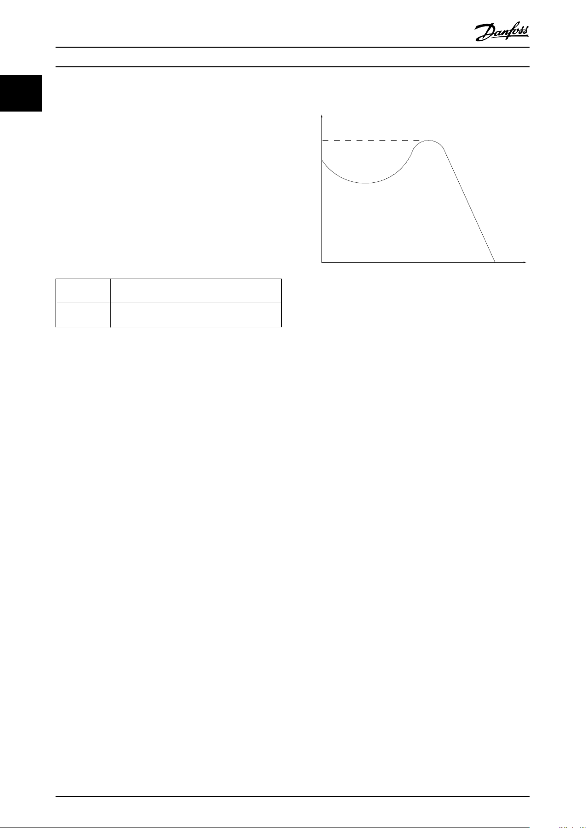
에서 설명한 바와 같이
브레이크어웨이 토오크
그림 1.1 브레이크어웨이 토오크
η
VLT
AC 드라이브 효율은 입력 전원 및 출력 전원 간의 비율
로 정의됩니다.
기동 불가 명령
표 1.4
제어 명령 그룹 1에 속하는 정지 명령입니다(
참
조).
정지 명령
표 1.4
을(를) 참조하십시오.
아날로그 지령
아날로그 입력 단자 53 또는 54에 전달되는 신호이며
전압 또는 전류일 수 있습니다.
전류 입력: 0–20 mA 및 4–20 mA
•
전압 입력: 0–10 V DC
•
버스통신 지령
직렬 통신 포트(FC 포트)에 전달되는 신호입니다.
프리셋 지령
프리셋 지령은 -100%에서 +100% 사이의 지령 범위에
서 설정할 수 있는 지령입니다. 디지털 단자를 통해 8개
의 프리셋 지령을 선택할 수 있습니다.
Ref
MAX
100% 전체 범위 값(일반적으로 10 V, 20 mA)에서의
지령 입력과 결과 지령 간의 관계를 결정합니다. 최대
지령 값이며
Ref
MIN
파라미터 3-03 최대 지령
에서 설정합니다.
0% 값(일반적으로 0 V, 0 mA, 4 mA)에서의 지령 입력
과 결과 지령 간의 관계를 결정합니다. 최소 지령 값은
파라미터 3-02 최소 지령
에서 설정됩니다.
8 Danfoss A/S © 04/2018 All rights reserved. MG18C839

소개 설계지침서
아날로그 입력
아날로그 입력은 AC 드라이브의 각종 기능을 제어하는
데 사용합니다.
아날로그 입력에는 다음과 같은 두 가지 형태가 있습니
다.
전류 입력: 0–20 mA 및 4–20 mA
•
전압 입력: 0–10 V DC
•
아날로그 출력
아날로그 출력은 0-20mA 신호, 4-20mA 신호 또는 디
지털 신호를 공급할 수 있습니다.
자동 모터 최적화, AMA
AMA 알고리즘은 정지 상태에서 연결된 모터의 전기적
인 파라미터를 결정하며 모터 케이블의 길이를 기반으
로 저항을 보상합니다.
디지털 입력
디지털 입력은 AC 드라이브의 각종 기능을 제어하는
데 사용할 수 있습니다.
디지털 출력
AC 드라이브는 24VDC(최대 40 mA) 신호를 공급할 수
있는 두 개의 고정 상태 출력을 제공합니다.
릴레이 출력
AC 드라이브는 두 개의 프로그래밍 가능한 릴레이 출
력을 제공합니다.
ETR
Electronic Thermal Relay(전자 써멀 릴레이)의 약자
이며 실제 부하 및 시간을 기준으로 한 써멀 부하 계산
입니다. 모터 온도의 측정과 모터의 과열 방지를 그 목
적으로 합니다.
초기화
초기화가 수행되면(
라이브의 프로그래밍 가능한 파라미터가 초기 설정으로
복귀합니다.
파라미터 14-22 작동 모드
또는 화재 모드 기록을 초기화하지 않습니다.
단속적 듀티 사이클
단속적 듀티 정격은 듀티 사이클의 시퀀스를 나타냅니
다. 각각의 사이클은 부하 기간과 부하 이동 기간으로
구성되어 있습니다. 단속 부하로 운전하거나 정상 부하
로 운전할 수 있습니다.
LCP
현장 제어 패널(LCP)은 AC 드라이브를 제어하고 프로
그래밍하기에 완벽한 인터페이스로 구성되어 있습니다.
제어 패널은 IP20 제품의 경우, 탈착식이며 IP54 제품
의 경우, 고정식입니다. 설치 키트 옵션을 사용하여 AC
드라이브에서 최대 3미터(9.8 ft) 거리, 다시 말해, 전면
패널에 설치할 수 있습니다.
Lsb
Least significant bit(최하위 비트)의 약자입니다.
MCM
미국의 케이블 단면적 측정 단위인 Mille Circular Mil
의 약자입니다. 1 MCM = 0.5067 mm2.
파라미터 14-22 작동 모드
은 통신 파라미터, 결함 기록
) AC 드
Msb
Most significant bit(최상위 비트)의 약자입니다.
온라인/오프라인 파라미터
온라인 파라미터에 대한 변경 사항은 데이터 값이 변경
되면 즉시 적용됩니다. [OK]를 눌러 오프라인 파라미터
를 활성화합니다.
PI 제어기
PI 제어기는 변화하는 부하에 따라 출력 주파수를 자동
조정하여 속도, 압력, 온도 등을 원하는 수준으로 유지
합니다.
RCD
Residual current device(잔류 전류 장치)의 약자입니
다.
셋업
셋업 2개의 파라미터 설정을 저장할 수 있습니다. 2개
의 파라미터 셋업을 서로 변경할 수 있으며 하나의 셋
업이 활성화되어 있더라도 다른 셋업을 수정할 수 있습
니다.
미끄럼 보상
AC 드라이브는 모터의 미끄럼 보상을 위해 모터의 회
전수를 거의 일정하도록 하는 모터 부하를 측정하고 그
에 따라 주파수를 보완하여 줍니다.
스마트 로직 컨트롤러(SLC)
SLC는 관련 사용자 정의 이벤트가 SLC에 의해 참
(TRUE)으로 결정되었을 때 실행된 사용자 정의 동작의
시퀀스입니다.
써미스터
온도에 따라 작동되는 저항이며, AC 드라이브 또는 모
터의 온도를 감시하는데 사용됩니다.
트립
예를 들어, AC 드라이브의 온도가 너무 높거나 AC 드
라이브가 모터, 공정 또는 기계장치의 작동을 방해하는
경우 등 결함이 발생한 상태입니다. 결함의 원인이 없어
야만 재기동할 수 있으며 리셋을 실행하거나 또는 경우
에 따라 자동으로 리셋하도록 프로그래밍하여 트립 상
태를 해제할 수 있습니다. 사용자의 안전을 위해 트립을
사용하지 마십시오.
트립 잠김
AC 드라이브의 출력 단자가 단락된 경우 등 AC 드라이
브에 결함이 발생하여 사용자의 개입이 필요한 상태입
니다. 주전원을 차단하고 결함의 원인을 제거한 다음
AC 드라이브를 다시 연결해야만 잠긴 트립을 해제할
수 있습니다. 리셋을 실행하거나 또는 경우에 따라 자동
으로 리셋하도록 프로그래밍하여 트립 상태를 해제해야
만 재기동할 수 있습니다. 사용자의 안전을 위해 트립
잠김을 사용하지 마십시오.
VT 특성
펌프와 팬에 사용되는 가변 토오크 특성입니다.
+
VVC
전압 벡터 제어(VVC+)는 표준 V/f(전압/주파수) 비율
제어에 비해 가변되는 속도 지령 및 부하 토오크에서
유동성과 안정성을 향상시킵니다.
1
1
MG18C839 Danfoss A/S © 04/2018 All rights reserved. 9
소개
VLT® HVAC Basic Drive FC 101
1
1.7 역률
역률은 AC 드라이브가 주전원 공급에 가하는 부하의
크기입니다. 역률은 I1과 I
기본 전류, I
는 고조파 전류를 포함한 총 RMS 전류
RMS
간의 비율로, 여기서 I1은
RMS
입니다. 역률이 낮을수록 동일한 kW(출력)를 얻기 위해
I
가 높아집니다.
RMS
역률 =
3 × U × I1× cosϕ
3 × U × I
RMS
3상 제어의 역률:
역률
I
RMS
I1 × cosϕ1
=
2
= I
+ I
1
I
RMS
2
+ I
5
I
1
=
I
RMS
2
+ . . + I
7
sincecosϕ1 = 1
2
n
역률이 높으면 다른 고조파 전류는 낮아집니다.
AC 드라이브의 내장 DC 코일은 역률을 높여 주전원 공
급에 가해지는 부하를 최소화합니다.
1.8 규제 준수
AC 드라이브는 이 절에 설명된 규정을 준수하도록 설
계되어 있습니다.
1.8.1.1 최저 전압 규정
저전압 규정은 50–1000 V AC 및 75–1600 V DC 전
압 범위의 모든 전기 장비에 적용됩니다.
규정의 목적은 올바르게 설치 및 유지보수된 전기 장비
가 용도에 맞는 어플리케이션에서 운전할 때 신체 안전
을 보장하고 자산의 파손을 피하는 데 있습니다.
1.8.1.2 EMC 규정
EMC(전자기 호환성) 규정의 목적은 전자기 간섭을 줄
이고 전기 장비 및 설비의 방지를 강화하는 데 있습니
다. EMC 규정 2014/30/EU의 기본 보호 요구사항에 따
르면 전자기 간섭(EMI)을 유발하거나 EMI에 의해 그
작동이 영향을 받을 수 있는 장치는 전자기 간섭의 유
발을 제한하도록 설계되어야 하며 올바르게 설치, 유지
보수 및 용도에 맞게 사용할 경우 적절한 EMI 방지 수
준을 갖춰야 합니다.
전기 설비 장치는 단독으로 사용하든지 아니면 시스템
의 일부로 사용하든지 간에 CE 마크를 고려해야 합니
다. 시스템에 CE 마크가 필요한 것은 아니지만 EMC 규
정의 기본 보호 요구사항은 반드시 준수해야 합니다.
1.8.1 CE 마크
CE 마크(Communauté européenne)는 해당 제품 제조
업체가 모든 관련 EU 규정을 준수함을 의미합니다. AC
드라이브의 설계 및 제조에 적용 가능한 EU 규정은
표 1.5
에 수록되어 있습니다.
주의 사항
CE 마크는 제품의 품질을 규제하지 않습니다. CE 마크
에서 기술 사양을 추론해 낼 수는 없습니다.
주의 사항
안전 기능이 통합된 AC 드라이브는 기계류 규정을 준
수해야 합니다.
EU 규정 버전
최저 전압 규정 2014/35/EU
EMC 규정 2014/30/EU
ErP 규정
표 1.5 AC 드라이브에 적용 가능한 EU 규정
적합성 선언은 요청 시 제공해 드릴 수 있습니다.
1.8.1.3 ErP 규정
ErP 규정은 에너지 관련 제품에 대한 유럽 친환경 설계
규정입니다. 이 규정은 AC 드라이브를 포함한 에너지
관련 제품에 대한 친환경 설계 요구사항을 규정합니다.
이 규정은 에너지 공급의 안전성을 높이는 동시에 에너
지 효율 및 환경 보호 수준을 높이는 것을 목적으로 합
니다. 에너지 관련 제품의 환경 영향에는 제품 수명 전
체에 걸친 에너지 소비가 포함됩니다.
1.8.2 UL 준수
UL 준수
그림 1.2 UL
주의 사항
IP54 제품은 UL 인증을 받지 않았습니다.
AC 드라이브는 UL 508C 써멀 메모리 유지 요구사항을
준수합니다. 자세한 정보는 제품별
써멀 보호
편을 참조하십시오.
설계지침서의 모터
10 Danfoss A/S © 04/2018 All rights reserved. MG18C839
089
소개 설계지침서
1.8.3 RCM 마크 준수
그림 1.3 RCM 마크
RCM 마크 라벨은 전자기 호환성(EMC)의 관련 기술 표
준의 준수를 나타냅니다. RCM 마크 라벨은 전기 및 전
자 장치를 호주 및 뉴질랜드에 출시하는데 필요합니다.
RCM 마크 규제사항은 전도 방사 및 복사 방사만 다룹
니다. AC 드라이브의 경우, EN/IEC 61800-3에 명시된
방사 한계가 적용됩니다. 적합성 선언은 요청 시 제공해
드릴 수 있습니다.
1.8.4 EAC
1
1
그림 1.4 EAC 마크
EAC(EurAsian Conformity) 마크는 해당 제품이 유라
시아 경제연합(EurAsian Economic Union) 회원국으로
구성된 유라시아 관세동맹(EurAsian Customs Union)
에 따라 제품에 적용 가능한 모든 요구사항 및 기술 규
정을 준수함을 나타냅니다.
EAC 로고는 제품 라벨과 포장 라벨에 모두 표시되어야
합니다. EAC 지역 내에서 사용된 제품은 모두 EAC 지
역 내 댄포스로 보내야 합니다.
1.8.5 UkrSEPRO
그림 1.5 UkrSEPRO
UKrSEPRO 인증서는 우크라이나 규제 표준에 따라 제
품 및 서비스의 품질과 안전성뿐만 아니라 제조 안정성
을 보장합니다. UkrSepro 인증서는 우크라이나 영토로
들어오거나 우크라이나 영토 밖으로 나가는 모든 제품
의 세관 통과에 필요한 서류입니다.
MG18C839 Danfoss A/S © 04/2018 All rights reserved. 11
안전
VLT® HVAC Basic Drive FC 101
2 안전
22
2.1 공인 기사
AC 드라이브를 문제 없이 안전하게 운전하기 위해서는
올바르고 안정적인 운송, 보관, 설치, 운전 및 유지보수
가 필요합니다. 본 장비의 설치 또는 운전은 공인 기사
에게만 허용됩니다.
공인 기사는 교육받은 기사 중 해당 법률 및 규정에 따
라 장비, 시스템 및 회로를 설치, 작동 및 유지보수하도
록 승인된 기사로 정의됩니다. 또한 기사는 본 지침서에
수록된 지침 및 안전 조치에 익숙해야 합니다.
2.2 안전 주의사항
경고
최고 전압
교류 주전원 입력, 직류 공급 또는 부하 공유에 연결될
때 AC 드라이브에 고전압이 발생합니다. 설치, 기동 및
유지보수를 공인 기사가 수행하지 않으면 사망 또는 중
상으로 이어질 수 있습니다.
반드시 공인 기사가 설치, 기동 및 유지보수를
•
수행해야 합니다.
서비스 또는 수리 작업을 수행하기 전에 적절
•
한 전압 측정 장치를 사용하여 AC 드라이브에
전압이 남아 있지 않은지 확인합니다.
경고
의도하지 않은 기동
드라이브가 교류 주전원, 직류 공급 또는 부하 공유에
연결되어 있는 경우, 모터는 언제든지 기동할 수 있습니
다. 프로그래밍, 서비스 또는 수리 작업 중에 의도하지
않은 기동이 발생하면 사망, 중상 또는 장비나 자산의
파손으로 이어질 수 있습니다. 모터는 외부 스위치, 필
드버스 명령이나 LCP 또는 LOP의 입력 지령 신호를
이용하거나 MCT 10 셋업 소프트웨어를 사용한 원격
운전을 통해서나 결함 조건 해결 후에 기동할 수 있습
니다.
의도하지 않은 모터 기동을 방지하려면:
파라미터를 프로그래밍하기 전에 LCP의 [Off/
•
Reset]를 누릅니다.
드라이브를 주전원에서 연결 해제합니다.
•
드라이브를 교류 주전원, 직류 공급장치 또는
•
부하 공유에 연결하기 전에 드라이브, 모터 및
관련 구동 장비를 완벽히 배선 및 조립합니다.
경고
방전 시간
AC 드라이브에는 AC 드라이브에 전원이 인가되지 않
더라도 충전이 유지될 수 있는 DC 링크 컨덴서가 포함
되어 있습니다. 경고 LED 표시 램프가 꺼져 있더라도
최고 전압이 남아 있을 수 있습니다. 전원을 분리한 후
서비스 또는 수리를 진행하기 전까지 지정된 시간 동안
기다리지 않으면 사망 또는 중상으로 이어질 수 있습니
다.
모터를 정지합니다.
•
교류 주전원 및 원격 DC 링크 전원 공급(배터
•
리 백업장치, UPS 및 다른 AC 드라이브에 연
결된 DC 링크 연결장치 포함)을 차단합니다.
PM 모터를 차단하거나 구속시킵니다.
•
컨덴서가 완전히 방전될 때까지 기다립니다.
•
최소 대기 시간은
서비스 또는 수리 작업을 수행하기 전에 적절
•
한 전압 측정 장치를 사용하여 컨덴서가 완전
히 방전되었는지 확인합니다.
전압[V] 출력 범위 [kW(HP)] 최소 대기 시간(분)
3x200 0.25–3.7 (0.33–5) 4
3x200 5.5–11 (7–15) 15
3x400 0.37–7.5 (0.5–10) 4
3x400 11–90 (15–125) 15
3x600 2.2–7.5 (3–10) 4
3x600 11–90 (15–125) 15
표 2.1 방전 시간
표 2.1
에 명시되어 있습니다.
경고
누설 전류 위험
누설 전류가 3.5 mA를 초과합니다. AC 드라이브를 올
바르게 접지하지 못하면 사망 또는 중상으로 이어질 수
있습니다.
공인 전기설치 인력이 장비를 올바르게 접지하
•
게 합니다.
12 Danfoss A/S © 04/2018 All rights reserved. MG18C839
안전 설계지침서
경고
장비 위험
회전축 및 전기 장비에 접촉하면 사망 또는 중상으로
이어질 수 있습니다.
반드시 해당 교육을 받은 공인 기사가 설치, 기
•
동 및 유지보수를 수행해야 합니다.
전기 작업 시에는 항상 국가 및 현지 전기 규
•
정을 준수해야 합니다.
본 설명서의 절차를 따릅니다.
•
주의
내부 결함 위험
AC 드라이브가 올바르게 닫혀 있지 않으면 AC 드라이
브의 내부 결함 시 중상으로 이어질 수 있습니다.
전원을 공급하기 전에 모든 안전 덮개가 제자
•
리에 안전하게 고정되어 있는지 확인해야 합니
다.
2 2
MG18C839 Danfoss A/S © 04/2018 All rights reserved. 13
120
100
80
60
40
20
0
20 40 60 80 100 120 140 160 180
120
100
80
60
40
20
0 20 40 60 80 100 120 140 160 180
Volume %
Volume %
INPUT POWER % PRESSURE %
SYSTEM CURVE
FAN CURVE
A
B
C
130BA781.11
ENERGY
CONSUMED
제품 개요
3 제품 개요
3.1 이점
VLT® HVAC Basic Drive FC 101
33
3.1.1 팬 및 펌프 제어에 AC 드라이브를
사용하는 이유
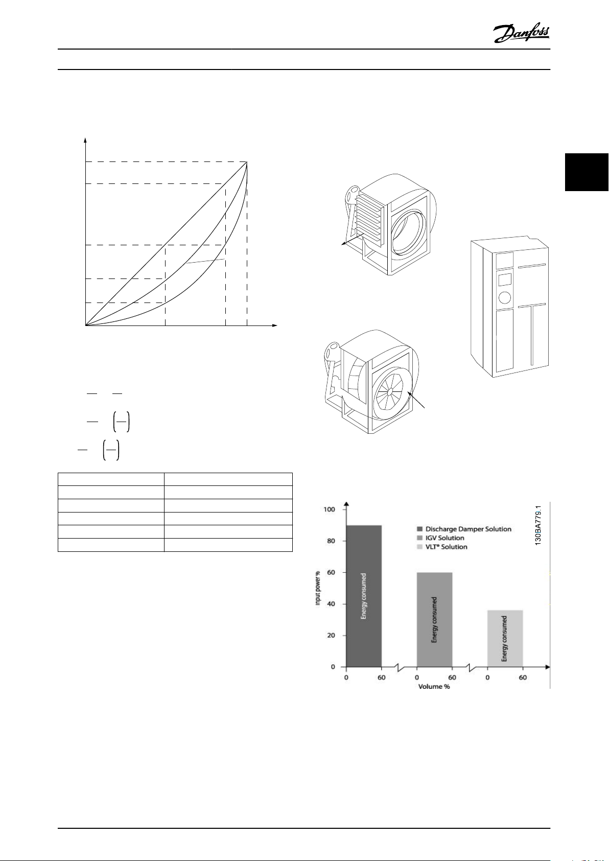
AC 드라이브는 원심 팬 및 펌프가 비례의 법칙을 따른
다는 이점을 활용합니다. 자세한 정보는
너지 절감의 예
를 참조하십시오.
장을 3.1.3 에
3.1.2 명확한 이점 - 에너지 절감
팬 또는 펌프의 속도를 제어하는 데 AC 드라이브를 사
용하는 명확한 이점은 바로 전기 에너지 절감입니다.
AC 드라이브는 다른 대체 제어 시스템 및 기술과 비교
하더라도 팬 및 펌프 시스템을 제어하는 데 가장 적합
한 에너지 제어 시스템입니다.
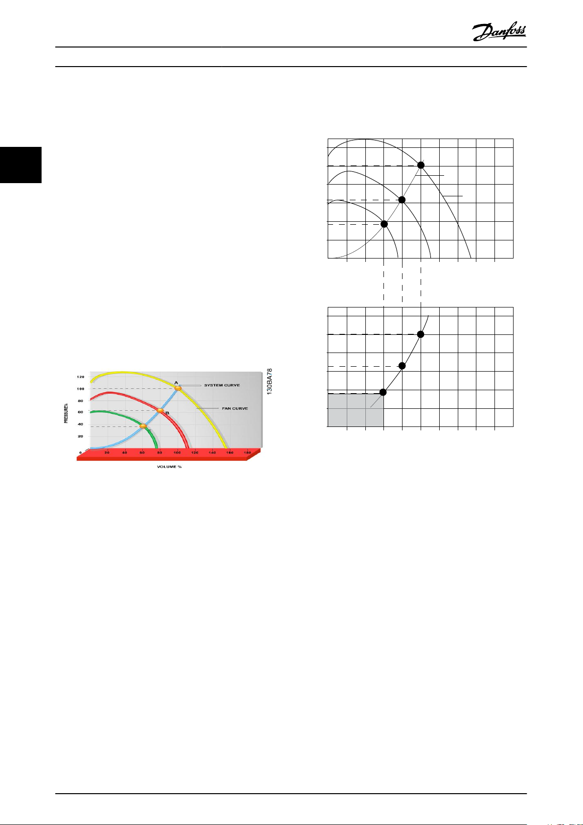
그림 3.1 팬 용적이 감소된 경우의 팬 곡선(A, B 및 C)
그림 3.2 AC 드라이브 솔루션을 이용한 에너지 절감
팬 용량을 60%로 줄이는 데 AC 드라이브를 사용하면
일반적인 어플리케이션에서 50% 이상의 에너지 절감이
가능합니다.
3.1.3 에너지 절감의 예
그림 3.3
량이 제어됩니다. 정격 속도에서 20%만 속도를 줄여도
유량 또한 20%까지 감소합니다. 이는 유량이 RPM에
직비례하기 때문입니다. 반대로 전기 소비량은 50%까
지 감소합니다.
시스템이 일 년에 몇 일 정도만 100%의 유량을 공급하
고 나머지 기간 동안은 평균적으로 정격 유량의 80%를
공급하면 되는 경우, 절감된 에너지량은 50%를 초과합
니다.
에서 보는 바와 같이 RPM을 변경함으로써 유
14 Danfoss A/S © 04/2018 All rights reserved. MG18C839
n
100%
50%
25%
12,5%
50% 100%
80%
80%
175HA208.10
Power ~n
3
Pressure ~n
2
Flow ~n
130BA782.10
Discharge
damper
Less energy savings
IGV
Costlier installation
Maximum energy savings
제품 개요 설계지침서
그림 3.3
는 RPM에 대한 유량, 압력 및 소비전력의 의
존도를 설명합니다.
그림 3.3 비례의 법칙
Q
n
1
Q
2
H
H
=
1
2
=
=
1
n
2
n
1
n
2
3
n
1
n
2
유량
압력
역
:
:
:
P
P
1
2
그림 3.3
는 팬 용적이 60%까지 줄었을 때 잘 알려진
세 가지 솔루션으로 얻을 수 있는 일반적인 에너지 절
감량을 보여줍니다.
그래프에서 보는 바와 같이 일반적인 어플리케이션에서
50% 이상의 에너지 절감을 달성할 수 있습니다.
3 3
2
그림 3.4 흔히 사용되는 3가지 에너지 절감 시스템
Q = 유량 P = 전력
Q1 = 정격 유량 P1 = 정격 전력
Q2 = 감소된 유량 P2 = 감소된 전력
H = 압력 n = 속도 제어
H1 = 정격 압력 n1 = 정격 속도
H2 = 감소된 압력 n2 = 감소된 속도
표 3.1 비례의 법칙
3.1.4 에너지 절감량 비교
댄포스 AC 드라이브 솔루션은 방전 댐퍼 솔루션 및 흡
입 가이드 베인(IGV) 솔루션과 같은 기존의 에너지 절
감 솔루션에 비해 큰 절감량을 제공합니다. 이는 AC 드
라이브가 시스템의 써멀 부하에 따라 팬 속도를 제어할
수 있으며 AC 드라이브가 건물 관리 시스템, BMS로서
작동할 수 있게 하는 내장 설비가 AC 드라이브에 있기
때문입니다.
그림 3.5 에너지 절감
MG18C839 Danfoss A/S © 04/2018 All rights reserved. 15
500
[h]
t
1000
1500
2000
200100 300
[m
3
/h]
400
Q
175HA210.11
제품 개요
VLT® HVAC Basic Drive FC 101
방전 댐퍼는 소비전력을 줄입니다. 흡입 가이드 베인은
40%의 절감을 제공하지만 설치하기에 비쌉니다. 댄포
스 AC 드라이브 솔루션은 에너지 소비량을 50% 이상
줄이며 설치가 용이합니다. 이는 또한 소음, 기계적인
스트레스 및 마모율을 줄이며 전체 어플리케이션의 수
명을 연장합니다.
33
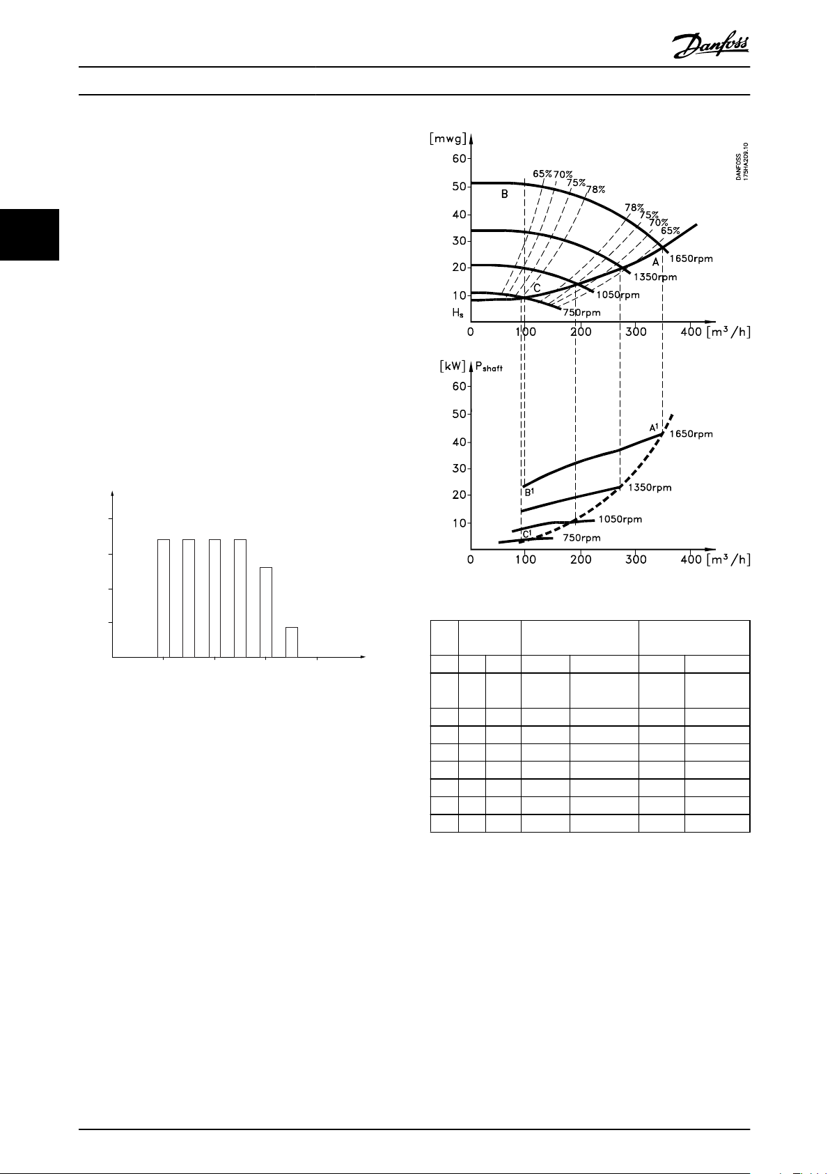
3.1.5 1년 동안 다양한 유량을 필요로 하
는 경우의 예
이 예는 펌프 데이터시트에서 얻은 펌프 특성을 기준으
로 계산됩니다.
그 결과, 주어진 유량 분포를 기준으로 1년 동안 50%를
초과하는 에너지 절감을 보여줍니다. 투자 회수 기간은
kWh당 가격과 AC 드라이브의 가격에 따라 다릅니다.
이 예에서는 밸브 및 일정 속도와 비교했을 때 투자 회
수 기간이 1년 미만입니다.
에너지 절감
P
= P
shaft
shaft output
그림 3.6 1년 동안의 유량 분포
그림 3.7 에너지
3
m
/
분포 밸브 조절 AC 드라이브 제어
h
% 시간 역 소모 역 소모
350 5 438 42.5 18.615 42.5 18.615
300 15 1314 38.5 50.589 29.0 38.106
250 20 1752 35.0 61.320 18.5 32.412
200 20 1752 31.5 55.188 11.5 20.148
150 20 1752 28.0 49.056 6.5 11.388
100 20 1752 23.0 40.296 3.5 6.132
Σ
100 8760 – 275.064 – 26.801
표 3.2 결과
A1 -
B
1
kWh
A1 -
C
1
kWh
16 Danfoss A/S © 04/2018 All rights reserved. MG18C839
Full load
% Full-load current
& speed
500
100
0
0 12,5 25 37,5 50Hz
200
300
400
600
700
800
4
3
2
1
175HA227.10
제품 개요 설계지침서
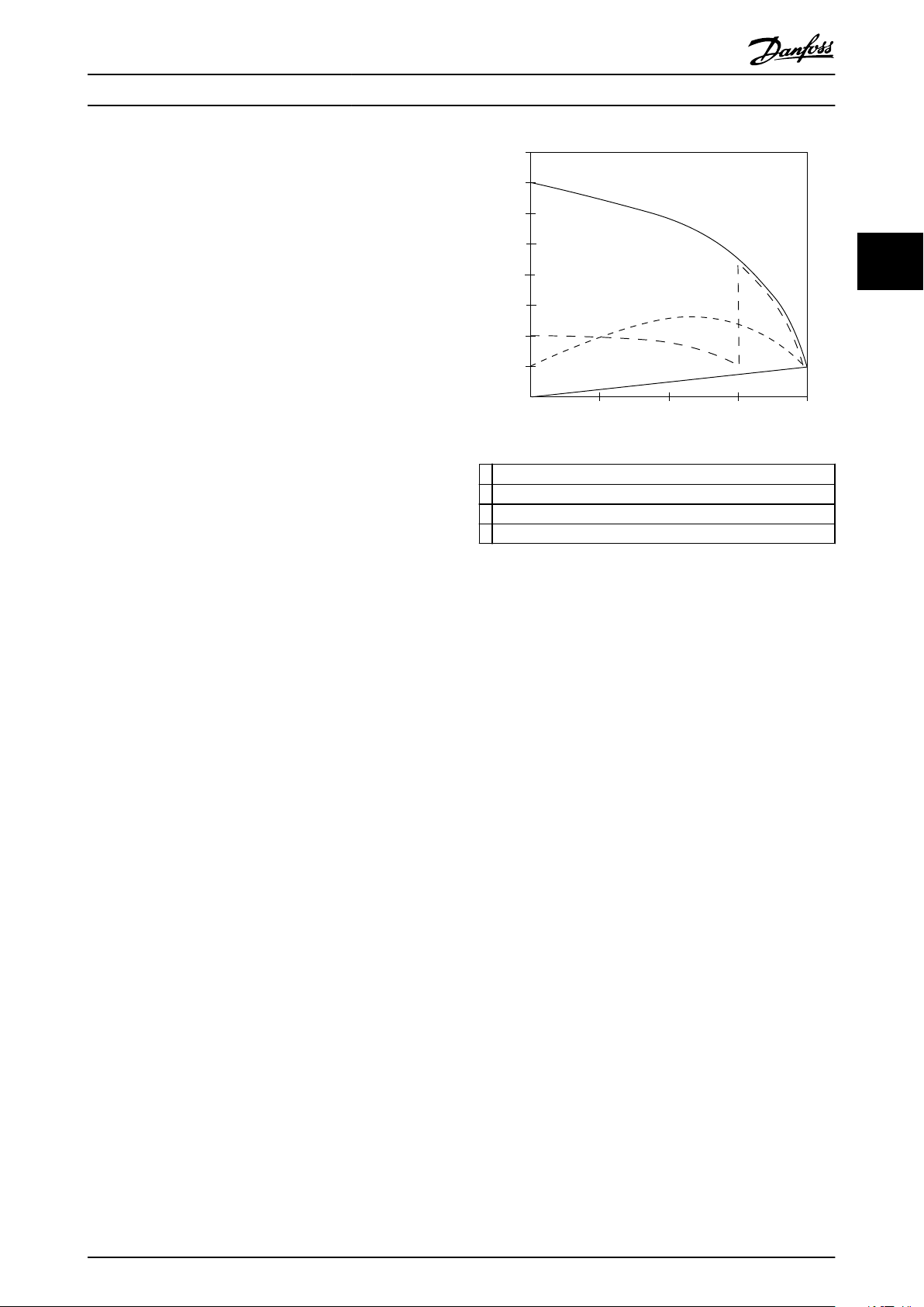
3.1.6 향상된 제어 성능
AC 드라이브가 시스템의 유량이나 압력을 제어하는 데
사용되는 경우, 제어 성능이 향상됩니다.
AC 드라이브는 팬 또는 펌프의 속도를 다양하게 할 수
있으며 유량 및 압력을 다양하게 제어할 수 있습니다.
또한 AC 드라이브는 팬 또는 펌프의 속도를 시스템의
새로운 유량 또는 압력 조건에 신속하게 적용할 수 있
습니다.
내장된 PI 제어 기능을 활용하여 공정(유량, 레벨 또는
압력)을 쉽게 제어할 수 있습니다.
3.1.7 스타/델타 스타터 또는 소프트 스
타터 필요 없음
대형 모터가 기동할 때 기동 전류를 제한하는 장비를
사용해야 하는 국가가 많습니다. 기존 시스템에서는 스
타/델타 스타터 또는 소프트 스타터가 널리 사용됩니다.
AC 드라이브가 사용되는 경우, 이러한 모터 스타터가
필요하지 않습니다.
그림 3.8
류를 많이 소모하지 않습니다.
에서와 같이 AC 드라이브는 정격 전류보다 전
1
VLT® HVAC Basic Drive FC 101
2 스타/델타 스타터
3 소프트 스타터
4 주전원 직기동
그림 3.8 기동 전류
3 3
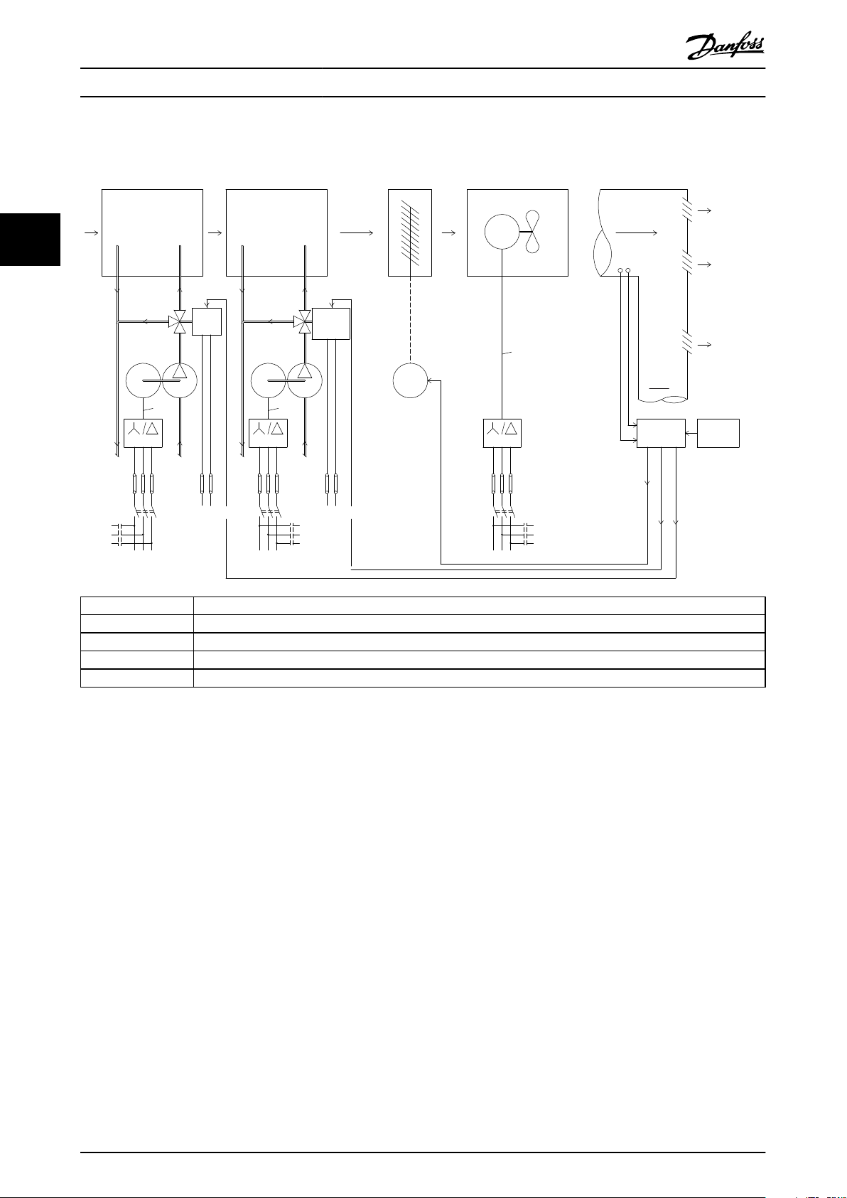
3.1.8 AC 드라이브를 통한 비용 절감
장을 3.1.9 AC 드라이브가 없는 경우
라이브가 다른 장비의 대체품으로 사용됨을 보여줍니
다. 각기 다른 시스템 2개의 설치 비용을 계산할 수 있
습니다. 예에서 2개의 시스템을 대략 동일한 가격으로
설치할 수 있습니다.
장을 1.5 추가 리소스
에 소개된 VLT® Energy Box 소
프트웨어를 사용하여 AC 드라이브로 달성할 수 있는
비용 절감분을 계산합니다.
의 예시는 AC 드
MG18C839 Danfoss A/S © 04/2018 All rights reserved. 17
M
- +
M
M
x6 x6
x6
175HA205.12
Valve
position
Starter
Fuses
LV
supply
P.F.C
Flow
3-Port
valve
Bypass
Return
Control
Supply
air
V.A.V
outlets
Duct
P.F.C
Mains
Fuses
Starter
Bypass
supply
LV
Return
valve
3-Port
Flow
Control
Valve
position
Starter
Power
Factor
Correction
Mains
IGV
Mechanical
linkage
and vanes
Fan
Motor
or
actuator
Main
B.M.S
Local
D.D.C.
control
Sensors
PT
Pressure
control
signal
0/10V
Temperature
control
signal
0/10V
Control
Mains
Cooling section Heating section
Fan sectionInlet guide vane
Pump Pump
제품 개요
VLT® HVAC Basic Drive FC 101
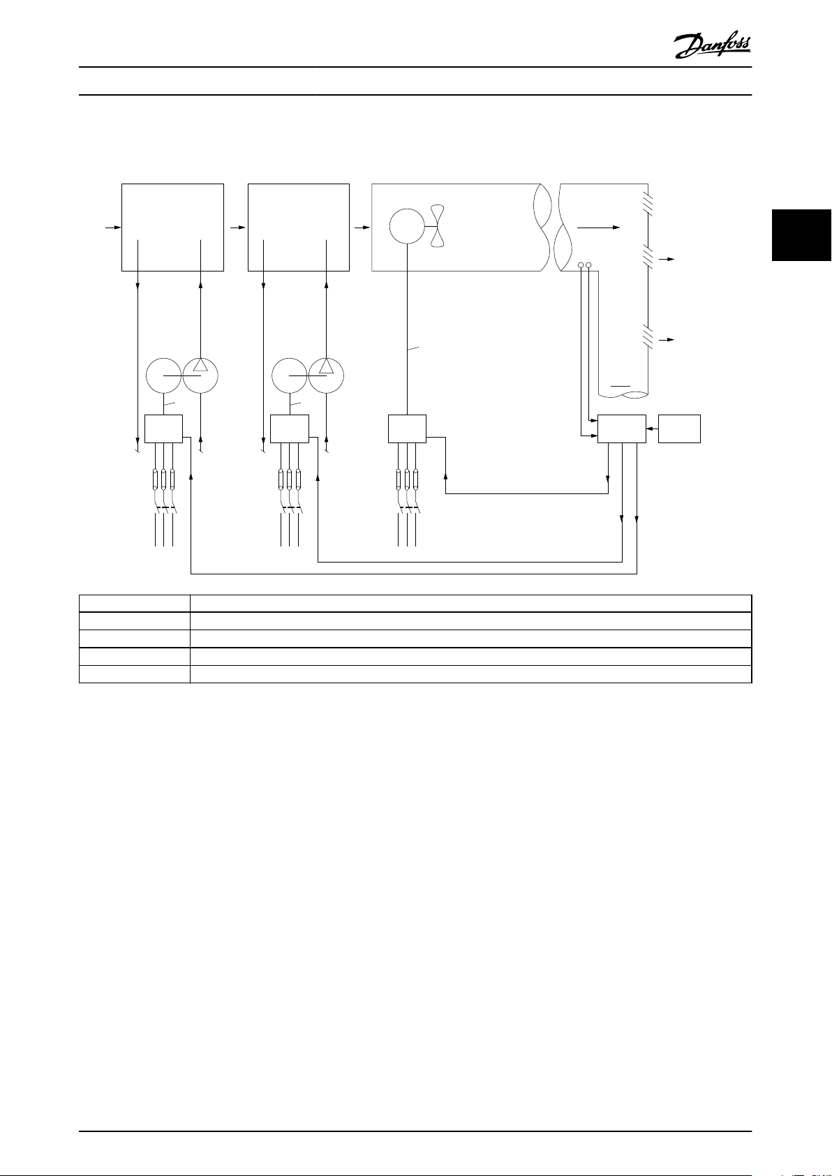
3.1.9 AC 드라이브가 없는 경우
33
D.D.C. Direct Digital Control(디지털 직제어)
E.M.S. Energy Management system(에너지 관리 시스템)
V.A.V. Variable Air Volume(가변 공기량)
Sensor P 압력
Sensor T 온도
그림 3.9 기존 팬 시스템
18 Danfoss A/S © 04/2018 All rights reserved. MG18C839
175HA206.11
Pump
Flow
Return
Supply
air
V.A.V
outlets
Duct
Mains
Pump
Return
Flow
Mains
Fan
Main
B.M.S
Local
D.D.C.
control
Sensors
Mains
Cooling section Heating section
Fan section
Pressure
control
0-10V
or
0/4-20mA
Control
temperature
0-10V
or
0/4-20mA
Control
temperature
0-10V
or
0/4-20mA
VLT
M
- +
VLT
M
M
P
T
VLT
x3 x3
x3
제품 개요 설계지침서
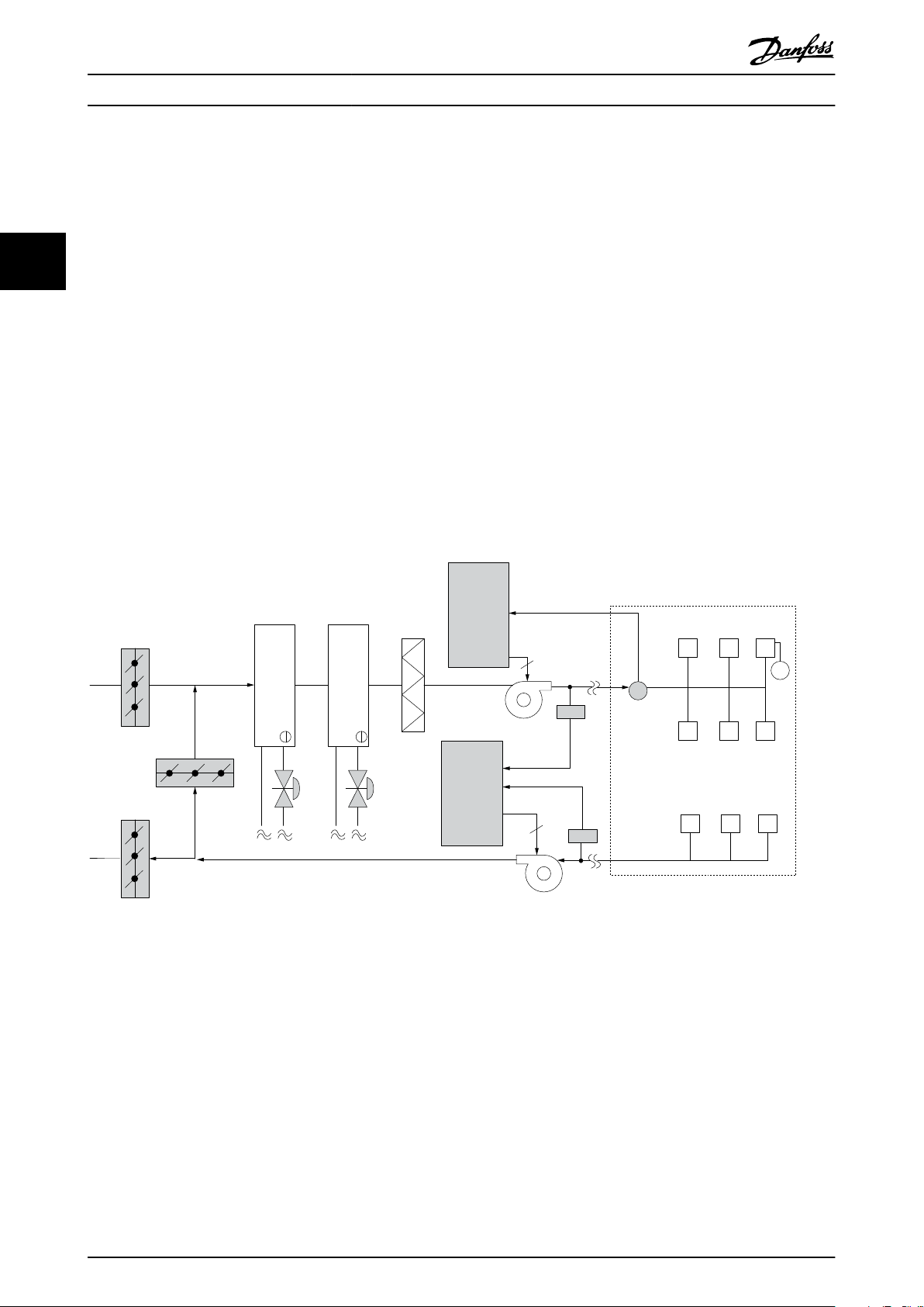
3.1.10 AC 드라이브가 있는 경우
3 3
D.D.C. Direct Digital Control(디지털 직제어)
E.M.S. Energy Management system(에너지 관리 시스템)
V.A.V. Variable Air Volume(가변 공기량)
Sensor P 압력
Sensor T 온도
그림 3.10 AC 드라이브에 의해 제어된 팬 시스템
MG18C839 Danfoss A/S © 04/2018 All rights reserved. 19
Frequency
converter
Frequency
converter
D1
D2
D3
Cooling coil
Heating coil
Filter
Pressure
signal
Supply fan
VAV boxes
Flow
Flow
Pressure
transmitter
Return fan
3
3
T
130BB455.10
제품 개요
VLT® HVAC Basic Drive FC 101
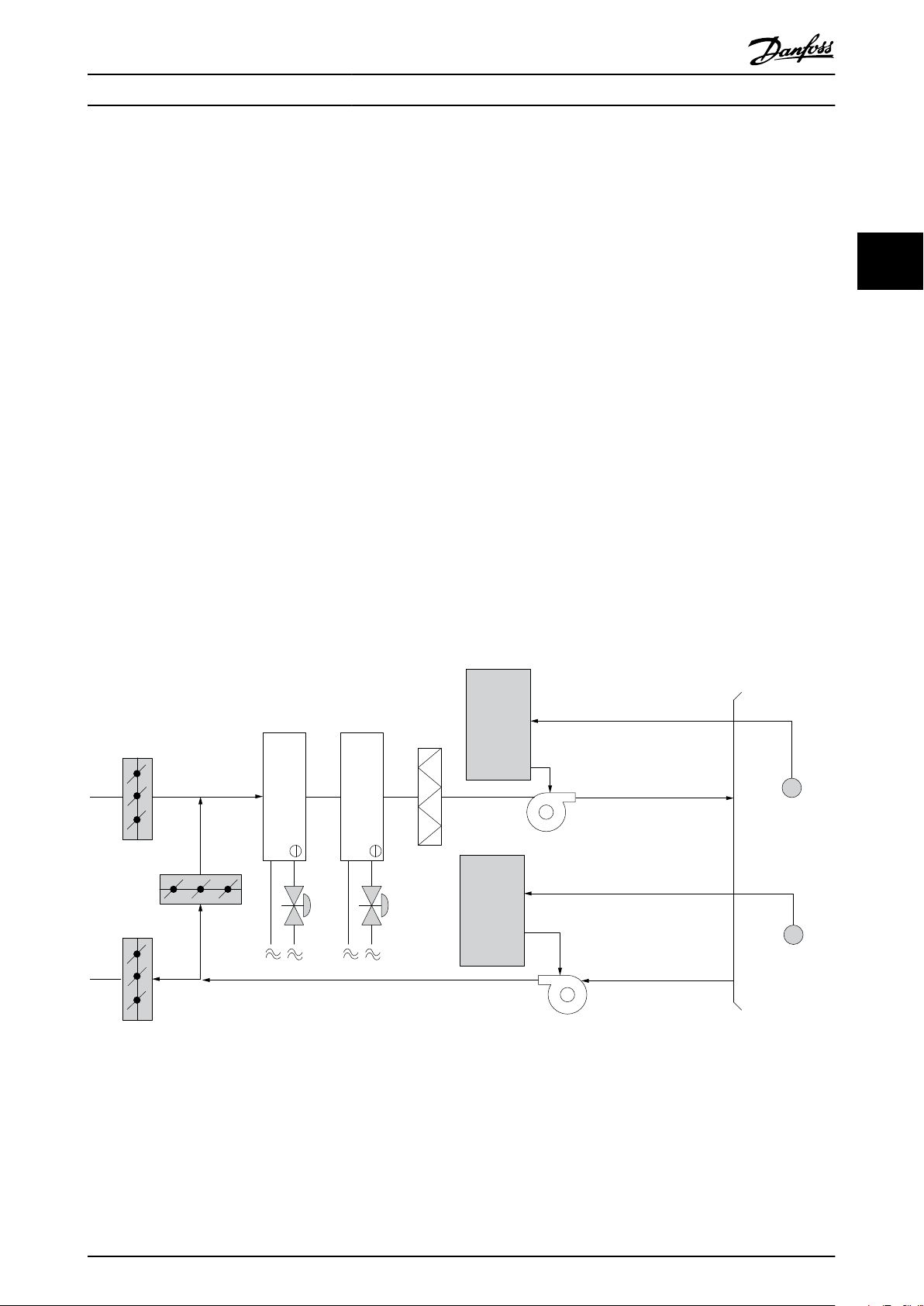
3.1.11 적용 예
다음 섹션에서는 HVAC 어플리케이션의 일반적인 예를 보여줍니다.
3.1.12 가변 공기량
33
VOV 또는 가변 공기량 시스템은 건물의 요구사항을 충족하기 위해 공조와 온도를 둘 다 제어하는 데 사용됩니다.
중앙 VAV 시스템은 건물 공조에 있어 가장 에너지 효율적인 방법으로 간주됩니다. 분산 시스템 대신 중앙 시스템을
설계하면 보다 높은 효율을 얻을 수 있습니다.
소형 모터와 분산형 공냉식 냉각기보다 효율이 높은 대형 팬과 대형 냉각기를 사용하면 보다 높은 효율을 얻을 수
있습니다. 유지보수 요구사항도 줄어들어 여기에서도 절감할 수 있습니다.
3.1.13 VLT 솔루션
댐퍼와 IGV가 덕트 작동 시 일정한 압력을 유지하는 데 사용되는 반면 AC 드라이브 솔루션은 에너지를 보다 많이
절감하고 설치 복잡성을 낮춥니다. AC 드라이브는 일부러 압력을 감소시키거나 팬 효율 감소를 야기하는 대신 팬의
속도를 낮춰 시스템에 필요한 유량과 압력을 제공합니다.
팬과 같은 원심 장치는 원심 법칙에 따라 동작합니다. 이는 팬의 속도가 감소함에 따라 팬에서 생성되는 압력과 유량
이 감소됨을 의미합니다. 따라서 팬의 소비전력은 크게 감소합니다.
VLT® HVAC Basic Drive FC 101의 PI 제어기를 사용하면 컨트롤러를 추가할 필요가 없습니다.
그림 3.11 가변 공기량
20 Danfoss A/S © 04/2018 All rights reserved. MG18C839
Frequency
converter
Frequency
converter
Pressure
signal
Cooling coil
Heating coil
D1
D2
D3
Filter
Pressure
transmitter
Supply fan
Return fan
Temperature
signal
Temperature
transmitter
130BB451.10
제품 개요 설계지침서
3.1.14 일정 공기량
CAV 또는 일정 공기량 시스템은 넓은 공용 구역에 최소한의 신선한 공기를 공급하는 데 주로 사용되는 중앙 공조
시스템입니다. 이 시스템은 VAV 시스템보다 먼저 활용되었으므로 다중 구역으로 구성된 구형 상용 건물에서도 찾을
수 있습니다. 이 시스템은 가열 코일과 함께 공기 처리 장치(AHU)를 활용하여 신선한 공기를 예열하며 건물 공조에
사용되는 경우가 많고 냉각 코일도 포함되어 있습니다. 팬 코일 장치는 개별 구역의 가열 및 냉각 요구사항을 지원하
는 데 사용되는 경우가 많습니다.
3.1.15 VLT 솔루션
3 3
AC 드라이브를 사용하면 에너지를 크게 절감하면서도 건물을 안정적으로 제어할 수 있습니다. 온도 센서 또는 CO
2
센서는 AC 드라이브에 대한 피드백 신호로 사용할 수 있습니다. 온도나 공기질을 제어하거나 아니면 둘 다를 제어하
든지 간에 CAV 시스템은 실제 건물 조건을 기준으로 작동하도록 제어할 수 있습니다. 제어 구역 내 인원 수가 감소
하므로 신선한 공기의 필요성도 감소합니다. CO2 센서는 낮은 수준을 감지하고 공급 팬 속도를 낮춥니다. 환기팬은
취출 풍량과 흡입 풍량 사이의 정적 압력 설정포인트 또는 고정 차이를 유지하도록 조정합니다.
온도 제어, 특히 공조 시스템에서 사용되는 온도 제어 기능을 사용하면 외부 온도가 다양할 뿐만 아니라 제어 구역
내 인원 수가 변경되므로 냉각 요구사항이 각기 다릅니다. 온도가 설정포인트보다 낮아지므로 취출팬은 팬 속도를 낮
출 수 있습니다. 환기 팬은 정적 압력 설정포인트를 유지하도록 조정합니다. 풍량이 감소함으로써 신선한 공기를 가
열 또는 냉각하는 데 사용된 에너지 또한 감소하므로 추가적인 절감이 가능합니다.
댄포스 HVAC 전용 AC 드라이브의 일부 기능을 활용하여 CAV 시스템의 성능을 개선할 수 있습니다. 공조 시스템
제어의 문제점 중 하나가 바로 낮은 공기질입니다. 피드백 또는 지령 신호와 관계 없이 취출 공기를 최소한으로 유지
하도록 프로그래밍 가능한 최소 주파수를 설정할 수 있습니다. AC 드라이브에는 또한 온도와 공기질을 둘 다 감시할
수 있는 PI 제어기 1개가 포함되어 있습니다. 온도 요구사항이 충족되더라도 AC 드라이브는 공기질 센서를 충족시키
기에 충분한 취출 공기를 유지합니다. 컨트롤러는 취출 덕트와 흡입 덕트 사이의 고정적인 차동 풍량을 유지함으로써
2개의 피드백 신호를 감시 및 비교하여 환기팬을 제어할 수 있습니다.
그림 3.12 일정 공기량
MG18C839 Danfoss A/S © 04/2018 All rights reserved. 21
Frequency
converter
Water Inlet
Water Outlet
CHILLER
Temperature
Sensor
BASIN
Conderser
Water pump
Supply
130BB453.10
제품 개요
VLT® HVAC Basic Drive FC 101
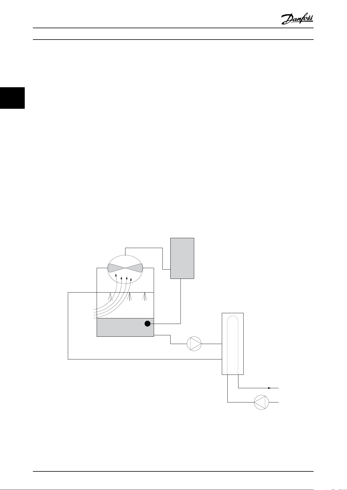
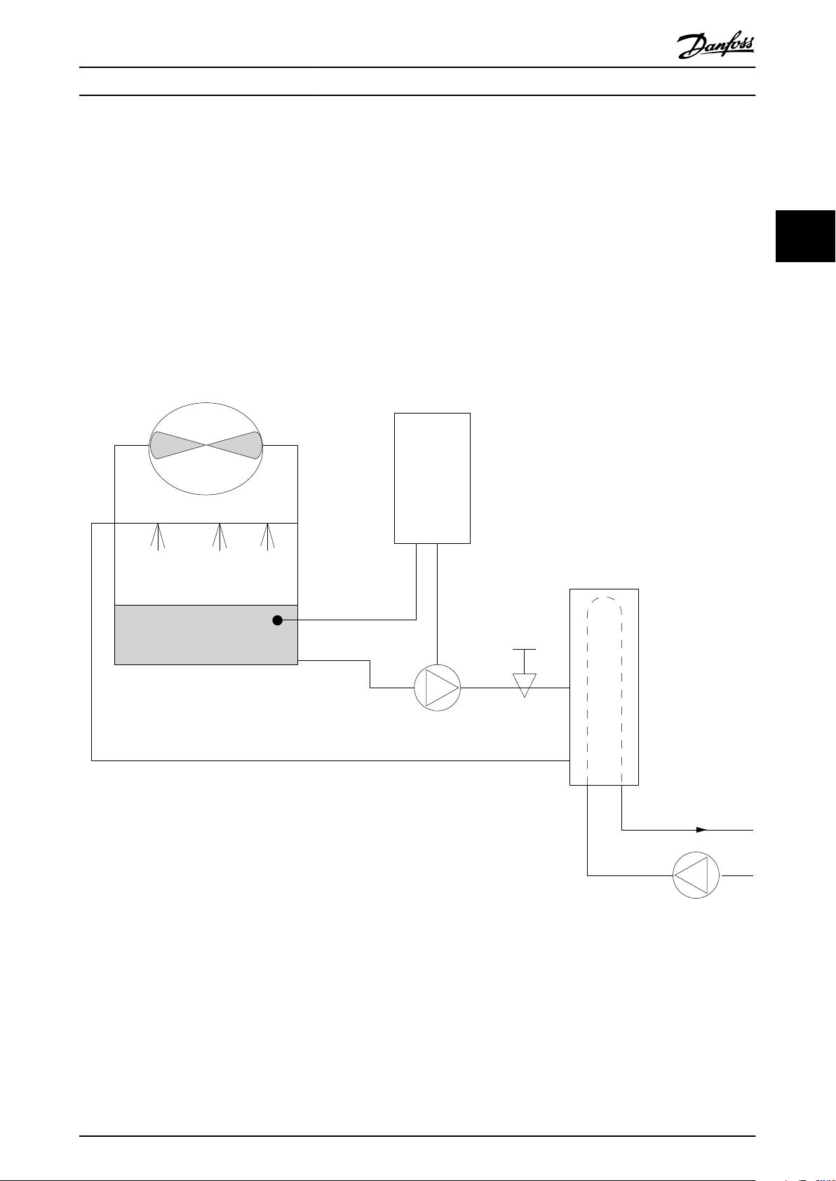
3.1.16 냉각 타워 팬
냉각 타워 팬은 수냉식 냉각기 시스템의 콘덴서 용수를 냉각합니다. 수냉식 냉각기는 가장 효율적으로 냉각수를 만드
는 방식을 제공합니다. 공냉식 냉각기에 비해 20% 이상 효율이 높습니다. 냉각 타워는 기후에 따라 냉각기에서 콘덴
서 용수를 냉각하는 데 가장 에너지 효율적인 방식인 경우가 많습니다.
냉각 타워는 증발을 통해 콘덴서 용수를 냉각합니다.
33
콘덴서 용수는 표면적을 넓히기 위해 냉각 타워가 충전될 때까지 냉각 타워에 분사됩니다. 타워 팬은 증발을 돕기 위
해 충진물과 분사된 용수를 통해 공기를 내보냅니다. 증발은 용수에서 에너지를 빼앗아 온도를 낮춥니다. 냉각된 용
수는 냉각기 콘덴서에 다시 펌핑되어 주기가 반복되는 냉각 타워 수조에 집수됩니다.
3.1.17 VLT 솔루션
AC 드라이브를 사용하면 콘덴서 용수 온도를 유지하는 데 필요한 속도로 냉각 타워 팬을 제어할 수 있습니다. AC
드라이브는 또한 필요에 따라 팬 전원을 켜고 끄는 데 사용할 수 있습니다.
댄포스 HVAC 전용 AC 드라이브의 일부 기능을 활용하여 냉각 타워 팬 어플리케이션의 성능을 개선할 수 있습니다.
냉각 타워 팬의 속도가 특정 속도 미만으로 낮아지므로 용수 냉각에 대한 팬의 효과가 감소합니다. 또한 타워 팬의
주파수를 제어하기 위해 기어박스를 활용하는 경우, 40-50%의 최소 속도가 필요합니다.
피드백이나 속도 지령에 보다 낮은 속도가 필요하더라도 최소 주파수를 유지하기 위해 사용자가 프로그래밍 가능한
최소 주파수 설정을 사용할 수 있습니다.
또한 기본 기능으로서, AC 드라이브를 프로그래밍하여 높은 속도가 필요할 때까지 슬립 모드로 전환하고 팬을 정지
할 수 있습니다. 또한 일부 냉각 타워 팬에는 진동을 야기할 수 있는 원치 않는 주파수가 있습니다. AC 드라이브에
서 바이패스 주파수 범위를 프로그래밍함으로써 이러한 주파수를 쉽게 피할 수 있습니다.
그림 3.13 냉각 타워 팬
22 Danfoss A/S © 04/2018 All rights reserved. MG18C839
Frequency
converter
Water
Inlet
Water
Outlet
BASIN
Flow or pressure sensor
Condenser
Water pump
Throttling
valve
Supply
CHILLER
130BB452.10
제품 개요 설계지침서
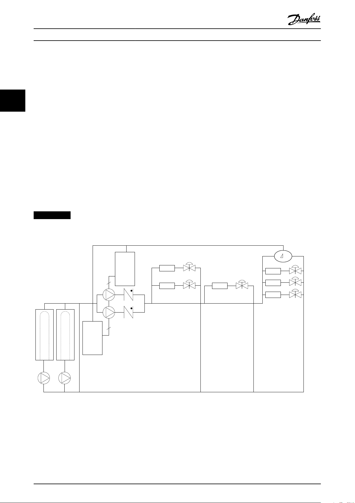
3.1.18 콘덴서 펌프
콘덴서 워터 펌프는 일차적으로 수냉식 냉각기와 관련 냉각 타워의 콘덴서부를 통해 용수를 순환시키는 데 사용됩니
다. 콘덴서 용수는 냉각기의 콘덴서부에서 열을 흡수하고 그 열을 냉각 타워 주변에 발산합니다. 이러한 시스템은 냉
각수를 만드는 데 가장 효율적인 방법을 제공하는 데 사용되며 공냉식 냉각기에 비해 20% 이상 효율이 높습니다.
3.1.19 VLT 솔루션
교축 밸브로 펌프 균형을 맞추거나 펌프 임펠러를 조정하는 대신 콘덴서 워터 펌프에 AC 드라이브를 추가할 수 있
습니다.
교축 밸브 대신 AC 드라이브를 사용하면 밸브에 의해 흡수되는 에너지를 절감할 수 있습니다. 이렇게 하면 15-20%
이상의 에너지를 절감할 수 있습니다. 펌프 임펠러 조정은 피할 수 없습니다. 따라서 조건이 바뀌고 보다 높은 유량
이 요구되는 경우, 반드시 임펠러를 교체해야 합니다.
3 3
그림 3.14 콘덴서 펌프
MG18C839 Danfoss A/S © 04/2018 All rights reserved. 23

제품 개요
VLT® HVAC Basic Drive FC 101
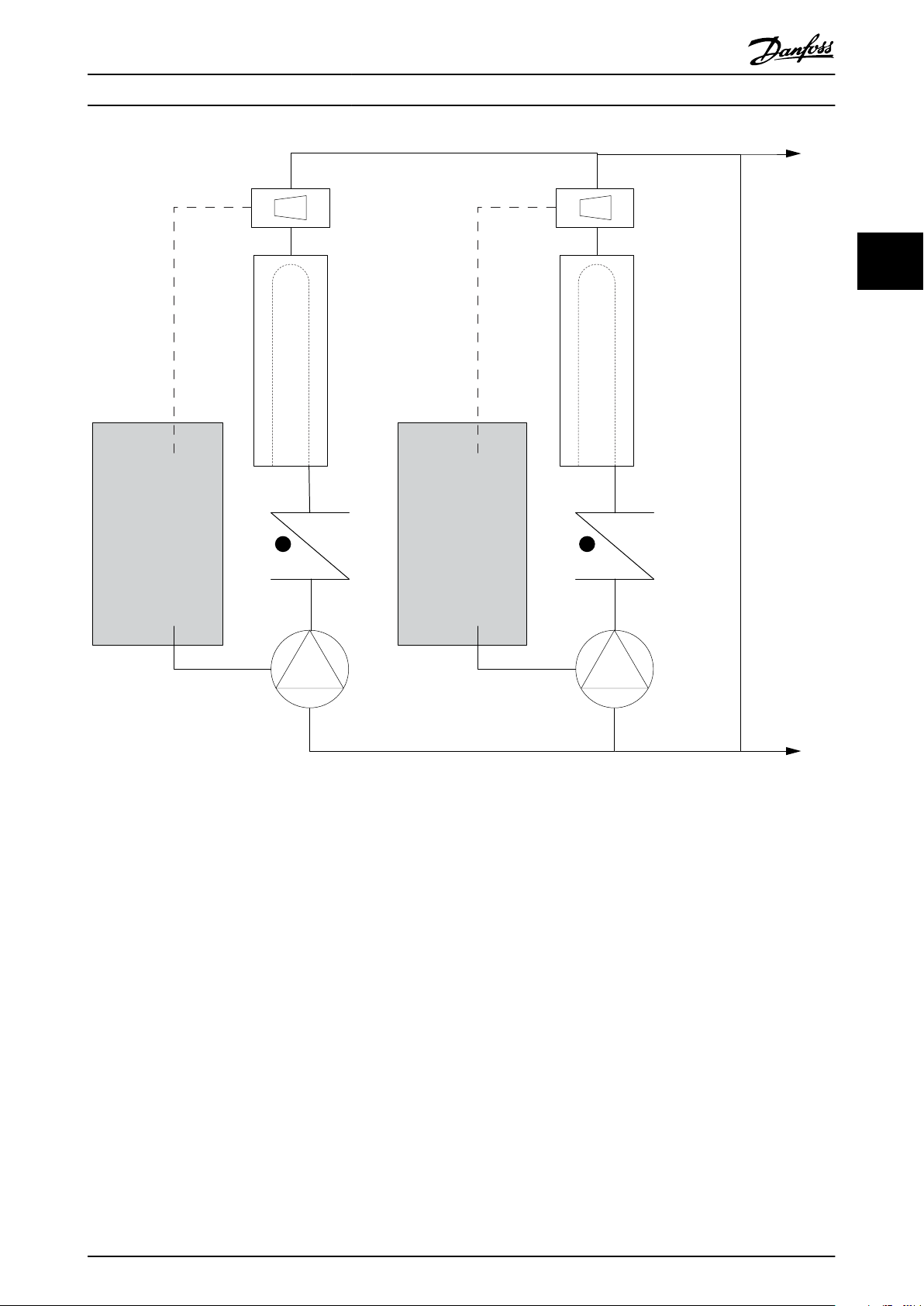
3.1.20 1차 펌프
1차/2차 펌프 시스템의 1차 펌프는 가변 유량에 노출되었을 때 운전 또는 제어가 어려운 장치를 통해 일정한 유량을
유지하는 데 사용할 수 있습니다. 1차/2차 펌핑 기술은 2차 분산 회로에서 1차 산출 회로를 분리합니다. 이렇게 하면
냉각기와 같은 장치가 일정한 설계 유량을 유지할 수 있고 올바르게 운전할 수 있는 반면 시스템의 다른 부분은 다
양한 유량을 감당할 수 있게 됩니다.
33
냉각기에서 증발기 유량이 감소하므로 냉각된 용수의 온도가 더 낮아지기 시작합니다. 이러한 상황이 발생하면 냉각
기는 냉각 용량 감소를 시도합니다. 유량이 많이 낮아지거나 너무 빨리 낮아지면 냉각기가 부하를 충분히 분산시킬
수 없게 되고 냉각기의 안전 기능으로 인해 냉각기가 트립되고 수동으로 리셋해야 합니다. 이는 대형 설비에서, 특히
1차/2차 펌프가 활용되지 않는 경우에 2개 이상의 냉각기가 병렬로 설치될 때 흔히 나타나는 상황입니다.
3.1.21 VLT 솔루션
시스템 용량과 1차 회로의 용량에 따라 1차 회로의 에너지 소비량이 크게 증가할 수 있습니다.
교축 밸브 및/또는 임펠러를 조정하는 대신 1차 시스템에 AC 드라이브를 추가할 수 있으며 이렇게 하면 운영 비용이
절감됩니다. 다음과 같은 2가지 제어 방법이 흔히 사용됩니다.
유량계
원하는 유량을 알 수 있거나 일정하기 때문에 각 냉각기의 방전 시 설치된 유량계는 펌프를 직접 제어하는 데 사용
할 수 있습니다. 내장된 PI 제어기를 사용하면 냉각기와 펌프가 스테이징되고 디스테이징됨에 따라 1차 배관 루프의
저항 변경을 보상하는 경우에도 AC 드라이브는 항상 적절한 유량을 유지합니다.
현장 속도 결정
작업자는 설계 유량에 도달할 때까지 출력 주파수를 낮추기만 하면 됩니다.
AC 드라이브를 사용하여 펌프 속도를 낮추는 것은 노동력이 필요하지 않다는 점과 펌프 효율이 더 높다는 것을 제
외하고는 펌프 임펠러의 조정과 매우 유사합니다. 균형 조정 콘택터는 적절한 유량에 도달할 때까지 펌프의 속도를
낮추고 속도를 고정 상태로 유지합니다. 펌프는 냉각기가 스테이징될 때마다 이 속도로 운전합니다. 1차 회로에는 시
스템 곡선의 변경을 야기할 수 있는 제어 밸브나 기타 장치가 없고 펌프 및 냉각기의 스테이징/디스테이징으로 인한
변동폭이 주로 작기 때문에 이 고정 속도가 적절히 유지됩니다. 시스템 수명 기간 중에 유량을 증가시킬 필요가 있는
경우, AC 드라이브는 새 펌프 임펠러로 교체하는 대신 펌프 속도를 증가시키기만 하면 됩니다.
24 Danfoss A/S © 04/2018 All rights reserved. MG18C839
Frequency
converter
Frequency
converter
CHILLER
CHILLER
Flowmeter
Flowmeter
F F
130BB456.10
제품 개요 설계지침서
3 3
그림 3.15 1차 펌프
MG18C839 Danfoss A/S © 04/2018 All rights reserved. 25
Frequency
converter
Frequency
converter
CHILLER
CHILLER
3
3
P
130BB454.10
제품 개요
VLT® HVAC Basic Drive FC 101
3.1.22 2차 펌프
1차/2차 냉각수 펌프 시스템의 2차 펌프는 냉각된 용수를 1차 산출 루프의 부하로 분산합니다. 1차/2차 펌프 시스템
은 하나의 배관 루프를 다른 배관 루프에서 순환수식으로 분리하는 데 사용됩니다. 이 경우에 1차 펌프는 냉각기를
통해 일정한 유량을 유지하는 데 사용하는 반면 2차 펌프는 유량을 다양하게 하고 제어 성능을 증대시키며 에너지를
절감하는 데 사용합니다.
33
가변 유량 시스템 설계에서 1차/2차 컨셉트가 사용되지 않는 경우, 유량이 많이 낮아지거나 너무 빨리 낮아지면 냉각
기가 부하를 올바르게 분산할 수 없습니다. 냉각기의 증발기 저온 안전 기능으로 인해 냉각기가 트립되고 수동으로
리셋해야 합니다. 이는 대형 설비에서, 특히 2개 이상의 냉각기가 병렬로 설치될 때 흔히 나타나는 상황입니다.
3.1.23 VLT 솔루션
2방향 밸브를 갖춘 1차-2차 시스템은 에너지 절감을 증대시키고 시스템 제어 문제를 보다 용이하게 하지만 실제 에
너지 절감 및 제어 가능성은 AC 드라이브를 추가함으로써 현실화됩니다.
센서 위치가 올바른 상태에서 AC 드라이브를 추가하면 펌프가 속도를 다양하게 하여 펌프 곡선 대신 시스템 곡선을
따르게 됩니다.
그 결과, 에너지가 버려지거나 과도한 가압이 대부분 발생하지 않게 하며 2방향 밸브 또한 영향을 받을 수 있습니다.
감시된 부하에 도달하면 2방향 밸브는 닫힙니다. 이렇게 되면 부하와 2방향 밸브에 걸쳐 측정된 차동 압력이 증가합
니다. 이 차동 압력이 증가하기 시작하면 설정포인트 값이라고도 하는 제어 헤드를 유지하기 위해 펌프 속도가 낮아
집니다. 이 설정포인트 값은 설계 조건 하에서 부하와 2방향 밸브의 압력 감소분을 합하여 계산됩니다.
주의 사항
여러 대의 펌프를 병렬로 구동할 때는 에너지 절감을 극대화하기 위해 개별 전용 AC 드라이브 또는 하나의 AC 드라
이브와 함께 동일한 속도로 구동해야 합니다.
그림 3.16 2차 펌프
26 Danfoss A/S © 04/2018 All rights reserved. MG18C839
130BB892.10
100%
0%
-100%
100%
Local
reference
scaled to
Hz
Auto mode
Hand mode
LCP Hand on,
off and auto
on keys
Local
Remote
Reference
Ramp
P 4-10
Motor speed
direction
To motor
control
Reference
handling
Remote
reference
P 4-14
Motor speed
high limit [Hz]
P 4-12
Motor speed
low limit [Hz]
P 3-4* Ramp 1
P 3-5* Ramp 2
Hand
On
Off
Reset
Auto
On
130BB893.10
제품 개요 설계지침서
3.2 제어 구조
파라미터 1-00 구성 모드
에서
[0] Open loop (개회로)
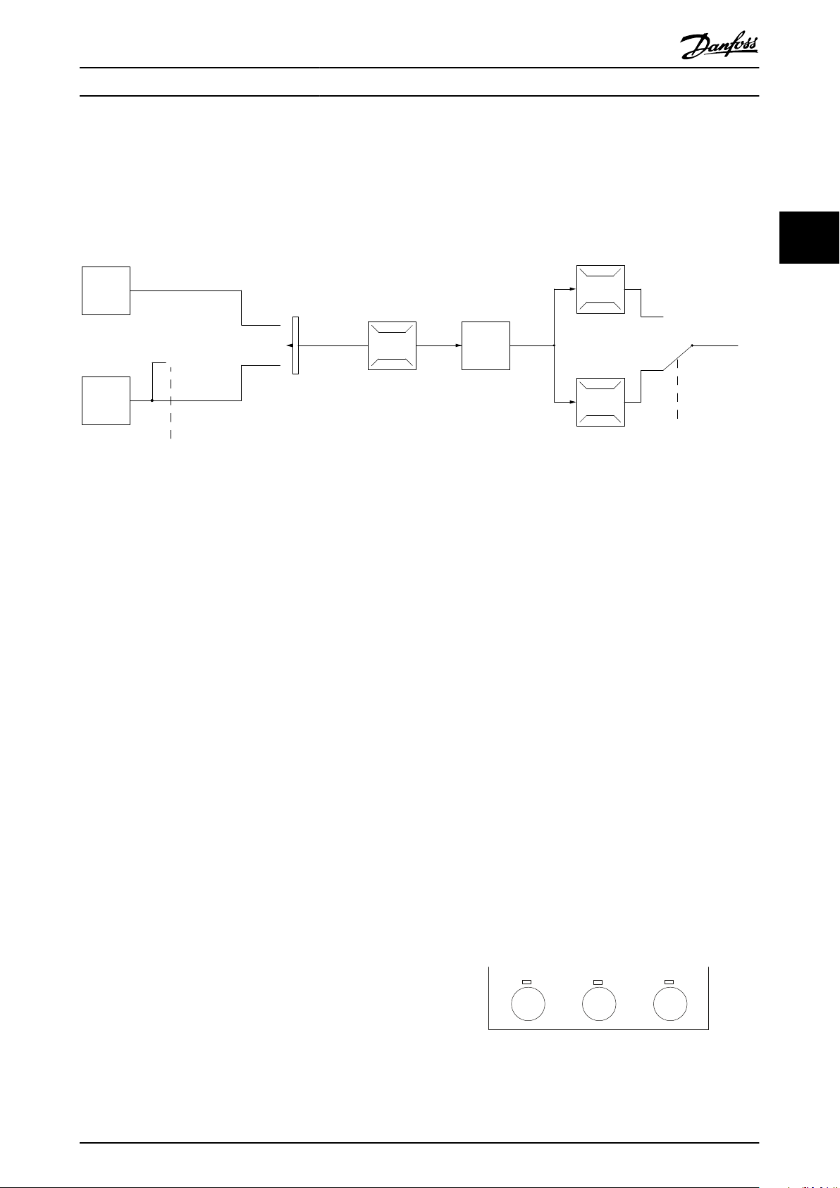
3.2.1 제어 구조 개회로
그림 3.17 개회로 구조
그림 3.17
드는 [0] Open loop (개회로)
에 나타난 구성에서
파라미터 1-00 구성 모
로 설정됩니다. 모터 제어
기로 전달되기 전에 가감속 한계 및 속도 한계를 통해
지령 처리 시스템의 결과 지령 또는 현장 지령이 수신
되고 보내집니다. 그러면 모터 제어기의 출력이 최대 주
파수 한계로 제한됩니다.
3.2.2 PM/EC+ 모터 제어
댄포스 EC+ 컨셉트는 댄포스 AC 드라이브가 운전하는
IEC 표준 외함 사이즈에서 고효율 PM 모터(영구 자석
모터)를 사용할 수 있게 합니다.
작동 절차는 댄포스 VVC+ PM 제어 방식을 활용하여
기존의 비동기식(유도) 모터를 사용하는 경우와 유사합
니다.
고객 이점:
모터 기술의 자유로운 선택(영구 자석 또는 유
•
도 모터).
유도 모터의 경우와 동일한 설치 및 운전.
•
시스템 구성품(예: 모터) 선정 시 제조업체 별
•
도 선택 가능.
최상의 구성품 선정을 통한 최상의 시스템 효
•
율.
기존 설비의 개장 가능.
•
전력 범위: 45 kW (60 hp) (200 V), 0.37–90
•
kW (0.5–121 hp) (400 V), 90 kW (121 hp)
(600 V)(유도 모터의 경우) 및 0.37–22 kW
(0.5–30 hp) (400 V)(PM 모터의 경우).
또는
[1] Closed loop (폐회로 중 하나를 선택합니다).
PM 모터의 전류 한계:
현재 최대 22 kW (30 hp)까지만 지원.
•
PM 모터로는 LC 필터를 지원하지 않음.
•
PM 모터로는 회생동력 백업 알고리즘을 지원
•
하지 않음.
시스템에서 고정자 저항 Rs의 완전 AMA만 지
•
원.
스톨 감지 없음(소프트웨어 버전 2.80부터 지
•
원).
3.2.3 현장(수동 운전) 및 원격(자동 운
전) 제어
AC 드라이브는 현장 제어 패널(LCP)을 통해 수동으로
작동하거나 아날로그/디지털 입력 또는 직렬 버스통신
을 통해 원격으로 작동할 수 있습니다.
터 0-40 LCP의 [Hand on] 키, 파라미터 0-44 LCP의
[Off/Reset] 키
키
에서 해당 모드가 설정된 경우, LCP의 [Hand On]
및
파라미터 0-42 LCP의 [Auto on]
및 [Off/Reset]을 통해 AC 드라이브를 기동 또는 정지
할 수 있습니다. [Off/Reset] 키를 통해 알람을 리셋할
수 있습니다.
그림 3.18 LCP 키
파라미
3 3
MG18C839 Danfoss A/S © 04/2018 All rights reserved. 27

7-30 PI
Normal/Inverse
Control
PI
Reference
Feedback
Scale to
speed
P 4-10
Motor speed
direction
To motor
control
130BB894.11
S
100%
0%
-100%
100%
*[-1]
_
+
130BB895.10
+
-
PI
P
P
P
Ref.
signal
Desired
ow
FB conversion
Ref.
FB
Flow
FB
signal
Flow
P 20-01
제품 개요
VLT® HVAC Basic Drive FC 101
현장 지령은
없이 구성 모드를 개회로로 강제 전환합니다.
파라미터 1-00 구성 모드
의 설정과 관계
예를 들어, 배관 내 정적 압력이 일정하게 유지되도록
펌프의 속도가 제어되는 펌프 어플리케이션을 고려해
보겠습니다. 정적 압력 값은 설정포인트 지령으로서 AC
현장 지령은 전원 차단 시 복원됩니다.
드라이브에 공급됩니다. 정적 압력 센서는 배관의 실제
정적 압력을 측정하고 이 데이터를 피드백 신호로서
33
3.2.4 제어 구조 폐회로
내부 컨트롤러를 사용하면 AC 드라이브가 제어되는 시
스템의 일부가 될 수 있습니다. AC 드라이브는 시스템
의 센서에서 피드백 신호를 수신합니다. 그리고 나서 이
피드백을 설정포인트 지령 값과 비교하고 이러한 두 신
AC 드라이브에 공급합니다. 피드백 신호가 설정포인트
지령보다 큰 경우, 압력을 줄이기 위해 AC 드라이브가
펌프를 감속합니다. 그와 유사한 방식으로 배관 압력이
설정포인트 지령보다 낮은 경우, 펌프에 의해 제공된 압
력을 증가시키기 위해 AC 드라이브가 자동으로 펌프를
가속합니다.
호 사이에 오류가 있는지 판단합니다. 그리고 나서 모터
의 속도를 조정하여 이 오류를 수정합니다.
그림 3.19 제어 구조 폐회로
AC 드라이브 폐회로 컨트롤러의 초기 설정값이 만족할
만한 성능을 제공하는 경우가 많기는 하지만 파라미터
를 조정하여 시스템 제어를 최적화할 수 있는 경우도
많습니다.
3.2.5 피드백 변환
일부 어플리케이션의 경우 피드백 신호를 변환하는 것
이 유용할 수 있습니다. 그 예 중 하나가 압력 신호를
사용하여 유량 피드백을 제공하는 것입니다. 압력의 제
곱근이 유량에 비례하므로 압력 신호의 제곱근은 유량
에 비례하는 값을 산출합니다.
십시오.
그림 3.20
을(를) 참조하
그림 3.20 피드백 신호 변환
28 Danfoss A/S © 04/2018 All rights reserved. MG18C839

Speed open
loop
mode
Input command:
freeze reference
Process
control
Scale to
Hz
Scale to
process
unit
Remote
reference/
setpoint
±200%
Feedback
handling
Remote
reference in %
maxRefPCT
minRefPct
min-max ref
Freeze
reference &
increase/
decrease
reference
±100%
Input commands:
Speed up/speed down
±200%
Relative
reference
=
X+X*Y/100
±200%
External reference in %
±200%
Parameter choise:
Reference resource 1,2,3
±100%
Preset reference
Input command:
preset ref bit0, bit1, bit2
+
+
Relative scalling reference
Intern resource
Preset relative reference
±100%
Preset reference 0 ±100%
Preset reference 1 ±100%
Preset reference 2 ±100%
Preset reference 3 ±100%
Preset reference 4 ±100%
Preset reference 5 ±100%
Preset reference 6 ±100%
Preset reference 7 ±100%
External resource 1
No function
Analog reference
±200 %
Local bus reference
±200 %
Pulse input reference
±200 %
Pulse input reference
±200 %
Pulse input reference
±200 %
External resource 2
No function
Analog reference
±200 %
Local bus reference
±200 %
External resource 3
No function
Analog reference
±200 %
Local bus reference
±200 %
Y
X
130BE842.10
제품 개요 설계지침서
3.2.6 지령 처리
개회로 및 폐회로 운전의 세부 내용.
3 3
그림 3.21 원격 지령을 보여주는 블록 다이어그램
원격 지령은 다음과 같이 구성됩니다.
•
•
•
•
AC 드라이브에서 최대 8개의 프리셋 지령을 프로그래
밍할 수 있습니다. 활성 프리셋 지령은 디지털 입력 또
는 직렬 통신 버스통신을 사용하여 선택할 수 있습니다.
지령은 또한 외부, 대부분의 경우, 아날로그 입력에서
제공될 수 있습니다. 이 외부 소스는 3가지 지령 소스
파라미터(
터 3-16 지령 2 소스
중 하나에 의해 선택됩니다. 모든 지령 소스와 버스통신
지령은 총 외부 지령을 산출하기 위해 추가됩니다. 외부
지령, 프리셋 지령 또는 외부 지령과 프리셋 지령의 합
은 활성 지령이 되도록 선택할 수 있습니다. 마지막으로
이 지령은
여 범위를 설정할 수 있습니다.
MG18C839 Danfoss A/S © 04/2018 All rights reserved. 29
프리셋 지령.
외부 지령(아날로그 입력 및 직렬 통신 버스통
신 지령).
프리셋 상대 지령
피드백으로 제어된 설정포인트.
파라미터 3-15 지령 1 소스, 파라미
및
파라미터 3-17 지령 3 소스
파라미터 3-14 프리셋 상대 지령
를 사용하
)
범위가 설정된 지령은 다음과 같이 계산됩니다.
지령
= X + X ×
여기서 X는 외부 지령, 프리셋 지령 또는 이 두 지령의
합이며 Y는 [%] 단위의
령
입니다.
Y,
파라미터 3-14 프리셋 상대 지령
라도 범위 설정에 의해 지령이 영향을 받지 않습니다.
Y
100
파라미터 3-14 프리셋 상대 지
가 0%로 설정되더

110%
100%
90 %
80
%
70 %
60 %
50 %
40 %
30 %
20 %
10 %
0
I
out
[%]
0
2
5
10
16
40
o
C
50
o
C
45
o
C
fsw[kHz]
130BC217.10
fsw[kHz]
20 10
0
10%
20%
30%
40%
50%
60%
70%
80%
90%
100%
110%
I
out
[%]
16
40
45
50
5
o
C
o
C
o
C
104 oF
113 oF
122
o
F
fsw[kHz]
20 10
0
10%
20%
30%
40%
50%
60%
70%
80%
90%
100%
110%
I
out
[%]
16
40
45
50
5
o
C
o
C
o
C
130BC219.10
제품 개요
VLT® HVAC Basic Drive FC 101
3.2.7 드라이브 폐회로 컨트롤러 튜닝
AC 드라이브의 폐회로 컨트롤러가 셋업되고 나면 컨트
롤러의 성능을 시험합니다.
득과 파라미터 20-94 PI 적분 시간
파라미터 20-93 PI 비례 이
의 초기 설정값을
사용해도 그 성능이 양호한 경우가 많습니다. 하지만 때
33
때로 이러한 파라미터 값을 최적화하여 보다 빠른 시스
템 응답을 제공하면서도 속도의 과도 현상을 제어하는
것이 유용할 수 있습니다.
3.2.8 수동 PI 조정
1. 모터를 기동합니다.
2.
파라미터 20-93 PI 비례 이득
을 0.3으로 설정
하고 피드백 신호가 공진을 시작할 때까지 값
을 늘립니다. 필요한 경우, AC 드라이브를 기
동 및 정지하거나 설정포인트 지령을 단계적으
로 변경하여 공진을 야기하게 합니다.
3. 피드백 신호가 안정화될 때까지 PI 비례 이득
을 줄입니다.
4. 비례 이득을 40-60%까지 줄입니다.
파라미터 20-94 PI 적분 시간
5.
을 20초로 설정
하고 피드백 신호가 공진을 시작할 때까지 값
을 줄입니다. 필요한 경우, AC 드라이브를 기
동 및 정지하거나 설정포인트 지령을 단계적으
로 변경하여 공진을 야기하게 합니다.
6. 피드백 신호가 안정화될 때까지 PI 적분 시간
을 늘립니다.
7. 적분 시간을 15-50%까지 늘립니다.
주위 구동 조건
3.3
그림 3.22 0.25–0.75 kW (0.34–1.0 hp), 200 V, 외함 사이
즈 H1, IP20
그림 3.23 0.37–1.5 kW (0.5–2.0 hp), 400 V, 외함 사이즈
H1, IP20
AC 드라이브는 50 °C (122 °F)에서 IEC/EN
60068-2-3 표준, EN 50178 9.4.2.2에 부합하도록 설
계되었습니다.
24시간 이상 측정한 주위 온도는 최대 주위 온도보다
최소 5 °C (41 °F) 이상 낮아야 합니다. AC 드라이브가
높은 주위 온도에서 작동하면 연속 출력 전류를 줄입니
다.
그림 3.24 2.2 kW (3.0 hp), 200 V, 외함 사이즈 H2, IP20
30 Danfoss A/S © 04/2018 All rights reserved. MG18C839

fsw[kHz]
20 10
0
10%
20%
30%
40%
50%
60%
70%
80%
90%
100%
110%
I
out
[%]
16
5
130BC220.11
40
45
50
o
C
o
C
o
C
104 oF
113 oF
122
o
F
fsw[kHz]
20 10
0
10%
20%
30%
40%
50%
60%
70%
80%
90%
100%
110%
I
out
[%]
16
40
45
50
5
o
C
o
C
o
C
130BC221.10
fsw[kHz]
20 10
0
10%
20%
30%
40%
50%
60%
70%
80%
90%
100%
110 %
I
out
[%]
16
5
40
45
50
o
C
o
C
o
C
104 oF
113 oF
122 oF
fsw[kHz]
20 10
0
10%
20%
30%
40%
50%
60%
70%
80%
90%
100%
110%
I
out
[%]
16
40
45
50
5
o
C
o
C
o
C
130BC223.10
fsw[kHz]
20 10
0
10%
20%
30%
40%
50%
60%
70%
80%
90%
100%
110%
I
out
[%]
16
40
45
50
5
o
C
o
C
o
C
130BC224.10
fsw[kHz]
20 10
0
10%
20%
30%
40%
50%
60%
70%
80%
90%
100%
110%
I
out
[%]
16
40
45
50
5
o
C
o
C
o
C
제품 개요 설계지침서
3 3
그림 3.25 2.2–4.0 kW (3.0–5.4 hp), 400 V, 외함 사이즈
H2, IP20
그림 3.26 3.7 kW (5.0 hp), 200 V, 외함 사이즈 H3, IP20
그림 3.28 5.5–7.5 kW (7.4–10 hp), 200 V, 외함 사이즈
H4, IP20
그림 3.29 11–15 kW (15–20 hp), 400 V, 외함 사이즈 H4,
IP20
그림 3.27 5.5–7.5 kW (7.4–10 hp), 400 V, 외함 사이즈
H3, IP20
MG18C839 Danfoss A/S © 04/2018 All rights reserved. 31
그림 3.30 11 kW (15 hp), 200 V, 외함 사이즈 H5, IP20

fsw[kHz]
20 10
0
10%
20%
30%
40%
50%
60%
70%
80%
90%
100%
110%
I
out
[%]
16
40
45
50
5
o
C
o
C
o
C
130BC226.10
I
out
[%]
f
sw
[kHz]
20
%
2 4 6 8 10 12
40
%
60
%
80
%
40
o
C
45
o
C
50
o
C
100
%
110
%
I
out
[%]
f
sw
[
kHz
]
20
%
2 4 6 8 10 12
40
%
60
%
80
%
40oC
45
o
C
50
o
C
100
%
110
%
I
out
[%]
f
sw
[kHz]
20
%
2 4 6 8 10 12
40
%
60
%
80
%
40oC
45
o
C
50
o
C
100
%
110
%
130BC229.10
I
out
[%]
f
sw
[kHz]
20
%
2 4 6 8 10 12
40
%
60
%
80
%
40oC
45
o
C
50
o
C
100
%
110
%
I
out
[%]
fsw [kHz]
20
%
2 4 6 8 10 12
40
%
60
%
80
%
40oC
45
o
C
50
o
C
100
%
110
%
제품 개요
VLT® HVAC Basic Drive FC 101
33
그림 3.31 18.5–22 kW (25–30 hp), 400 V, 외함 사이즈
H5, IP20
그림 3.32 15–18.5 kW (20–25 hp), 200 V, 외함 사이즈
H6, IP20
그림 3.34 45 kW (60 hp), 400 V, 외함 사이즈 H6, IP20
그림 3.35 22–30 kW (30–40 hp), 600 V, 외함 사이즈 H6,
IP20
그림 3.36 22–30 kW (30–40 hp), 200 V, 외함 사이즈
그림 3.33 30–37 kW (40–50 hp), 400 V, 외함 사이즈 H6,
H7, IP20
IP20
32 Danfoss A/S © 04/2018 All rights reserved. MG18C839

I
out
[%]
f
sw
[kHz]
20
%
2 4 6 8 10 12
40
%
60
%
80
%
40oC
45
o
C
50
o
C
100
%
110
%
I
out
[%]
f
sw
[kHz]
20
%
2 4 6 8 10 12
40
%
60
%
80
%
40oC
45
o
C
50
o
C
100
%
110
%
I
out
[%]
f
sw
[kHz]
20
%
2 4 6 8 10 12
40
%
60
%
80
%
40
o
C
45
o
C
50
o
C
100
%
110
%
I
out
[%]
f
sw
[kHz]
20 %
2 4 6 8 10 12
40 %
60 %
80 %
40oC
45
o
C
50
o
C
100 %
110 %
130BC235.10
I
out
[%]
f
sw
[kHz]
20
%
2 4 6 8 10 12
40
%
60
%
80
%
40
o
C
45
o
C
50
o
C
100
%
110
%
130BC236.10
I
out
[%]
f
sw
[kHz]
20
%
2 4 6 8 10 12
40
%
60
%
80
%
40oC
45
o
C
50
o
C
100
%
110
%
130BC237.10
제품 개요 설계지침서
3 3
그림 3.37 55–75 kW (74–100 hp), 400 V, 외함 사이즈
H7, IP20
그림 3.38 45–55 kW (60–74 hp), 600 V, 외함 사이즈
H7, IP20
그림 3.40 90 kW (120 hp), 400 V, 외함 사이즈 H8,
IP20
그림 3.41 75–90 kW (100–120 hp), 600 V, 외함 사이즈
H8, IP20
그림 3.39 37–45 kW (50–60 hp), 200 V, 외함 사이즈
H8, IP20
MG18C839 Danfoss A/S © 04/2018 All rights reserved. 33
그림 3.42 2.2–3 kW (3.0–4.0 hp), 600 V, 외함
사이즈 H9, IP20

I
out
[%]
f
sw
[kHz]
20
%
2 4 6 8 10 12
40
%
60
%
80
%
40oC
45
o
C
50
o
C
100
%
110
%
I
out
[%]
f
sw
[kHz]
20
%
2 4 6 8 10 12
40
%
60
%
80
%
40oC
45
o
C
50
o
C
100
%
110
%
fsw[kHz]
20 10
0
10%
20%
30%
40%
50%
60%
70%
80%
90%
100%
110%
I
out
[%]
16
40
45
50
5
o
C
o
C
o
C
130BC255.10
fsw[kHz]
20 10
0
10%
20%
30%
40%
50%
60%
70%
80%
90%
100%
110%
I
out
[%]
16
40
45
50
5
o
C
o
C
o
C
130BC256.10
130BD012.10
o
70%
80%
90%
0
I [%]
out
60%
100%
110%
2 84106
50 C
50%
40%
30%
20%
10%
0
o
40 C
12 14 16
fsw[kHz]
Iout [%]
f
sw [kHz]
20
%
2 4 6 8 10 12
40
%
60
%
80
%
40oC
45
o
C
50
o
C
100
%
110
%
130BC240.10
제품 개요
VLT® HVAC Basic Drive FC 101
33
그림 3.43 5.5–7.5 kW (7.4–10 hp), 600 V, 외함 사이즈
H9, IP20
그림 3.44 11–15 kW (15–20 hp), 600 V, 외함 사이즈
H10, IP20
그림 3.46 5.5–7.5 kW (7.4–10 hp), 400 V, 외함 사이즈
I3, IP54
그림 3.47 11–18.5 kW (15–25 hp), 400 V, 외함 사이즈
I4, IP54
그림 3.45 0.75–4.0 kW (1.0–5.4 hp), 400 V, 외함 사이즈
I2, IP54
34 Danfoss A/S © 04/2018 All rights reserved. MG18C839
그림 3.48 22–30 kW (30–40 hp), 400 V, 외함 사이즈 I6,
IP54

Iout [%]
f
sw [kHz]
20
%
2 4 6 8 10 12
40
%
60
%
80
%
40
o
C
45
o
C
50
o
C
100
%
110
%
130BC241.10
Iout [%]
f
sw [kHz]
20
%
2 4 6 8 10 12
40
%
60
%
80
%
40oC
45
o
C
50
o
C
100
%
110
%
Iout [%]
f
sw [kHz]
20
%
2 4 6 8 10 12
40
%
60
%
80
%
40oC
45
o
C
50
o
C
100
%
110
%
130BC243.10
제품 개요 설계지침서
그림 3.49 37 kW (50 hp), 400 V, 외함 사이즈 I6,
IP54
모터 또는 장치가 모터(예컨대, 팬)에 의해 구동될 때,
특정 주파수에서 잡음 또는 진동이 발생하는 경우 다음
의 파라미터 또는 파라미터 그룹을 구성하여 잡음 또는
진동을 줄이거나 없앱니다.
파라미터 그룹 4-6* 속도 바이패스.
•
파라미터 14-03 과변조를 [0] 꺼짐
•
으로 설정
합니다.
스위칭 방식 및 스위칭 주파수
•
파라미터 그룹
14-0* 인버터 스위칭.
파라미터 1-64 공진 제거
•
.
다음 세 가지 원인에 의해 AC 드라이브에 청각적 소음
이 발생합니다.
DC 링크 코일.
•
환기 팬.
•
RFI 필터 초크.
•
3 3
그림 3.50 45–55 kW (60–74 hp), 400 V, 외함 사이즈
I7, IP54
외함 사이즈
H1 43.6
H2 50.2
H3 53.8
H4 64
H5 63.7
H6 71.5
H7 67.5 (75 kW (100 hp) 71.5 dB)
H8 73.5
H9 60
H10 62.9
I2 50.2
I3 54
I4 67.4
I6 70
I7 62
I8 65.6
수준 [dBA]
1)
표 3.3 제품으로부터 1 m (3.28 ft) 떨어진 지점에서 측정된
일반적인 값
1) 이 값은 배경 소음이 35 dBA이고 팬이 최대 속도로 구동
하는 조건에서 측정됩니다.
AC 드라이브는 제시된 표준 절차,
표 3.4
에 따라 검사
되었습니다.
AC 드라이브는 현장의 벽면과 지면에 설치된 제품이나
그림 3.51 75–90 kW (100–120 hp), 400 V, 외함
사이즈 I8, IP54
MG18C839 Danfoss A/S © 04/2018 All rights reserved. 35
벽면 또는 지면에 볼트로 연결된 패널에 설치할 수 있
습니다.
IEC/EN 60068-2-6 진동(사인 곡선) - 1970
IEC/EN 60068-2-64 진동, 광대역 임의
표 3.4 표준

제품 개요
VLT® HVAC Basic Drive FC 101
AC 드라이브는 각종 기계부품과 전자부품으로 구성되
어 있어 주위 환경에 큰 영향을 받습니다.
EMC의 일반적 측면
3.4
3.4.1 EMC 방사의 개요
주의
설치 환경
33
공기 중의 수분, 분지 또는 가스가 전자부품에 영향을
주거나 손상시킬 수 있는 장소에 AC 드라이브를 설치
하지 마십시오. 필요한 보호 조치를 취하지 않으면 고장
이 발생할 가능성이 높아져 장비 파손 및 신체 상해를
야기할 가능성이 있습니다.
수분은 대기를 통하여 AC 드라이브 내부에서 응축될
수 있으며 전자부품과 금속부품을 부식시킬 수 있습니
다. 수증기, 유분, 염분 등도 전자부품과 금속부품을 부
식시킬 수 있습니다. 이러한 환경에서는 외함 등급 IP
54를 갖춘 장비를 사용합니다. 추가 보호 조치로서, 코
팅된 회로기판을 옵션(일부 전력 용량의 경우 표준)으로
주문할 수 있습니다.
먼지와 같은 공기 중의 분진은 AC 드라이브의 기계부
품, 전자부품의 결함 또는 과열 등을 유발할 수 있습니
다. 공기 중에 분진이 많은 장소에서 AC 드라이브를 사
용하면 대체로 팬 주변에 분진이 많이 모여 팬이 고장
날 수 있습니다. 분진이 많은 환경에 AC 드라이브를 설
치해야 하는 경우 반드시 IP54 등급의 외함 또는 IP20/
TYPE 1 장비용 외함 내부에 설치하십시오.
고온다습한 공기 중에 황, 질소, 염소 등의 부식성 가스
성분이 많이 포함되어 있으면 AC 드라이브의 부품에
화학 반응이 일어날 수 있습니다.
이와 같은 화학 반응은 전자부품을 급속히 손상시킵니
다. 이런 환경에 AC 드라이브를 설치해야 하는 경우 반
드시 외함 내부에 설치하고 AC 드라이브 내부에 신선
한 공기를 공급하여 부식성 가스가 침투하는 것을 방지
합니다.
또한 추가 보호 조치로서, 코팅된 회로기판을 옵션으로
선택 주문하여 사용할 수 있습니다.
AC 드라이브를 설치하기 전에 공기 중에 수분, 분진,
가스 등이 있는지 점검합니다. 이는 해당 환경에 설치되
어 있는 기존 장비를 점검하면 쉽게 확인할 수 있습니
다. 일반적으로 금속부품에 수분 또는 유분이 많이 묻어
있거나 금속부품이 부식되어 있으면 공기 중에 유해한
수분이 함유되어 있음을 의미합니다.
외함과 기존 전기 설비에 분진이 많이 쌓여 있으면 공
기 중에 분진이 많음을 의미합니다. 기존 설비의 동 레
일과 케이블 끝이 검게 변해 있으면 공기 중에 부식성
가스가 함유되어 있음을 의미합니다.
AC 드라이브 (및 기타 전기 장치)는 해당 환경을 간섭
할 수 있는 전자장 또는 자기장을 발생시킵니다. 이러한
현상에 따른 전자기 호환성(EMC)은 전력 및 장치의 고
조파 특성에 따라 다릅니다.
시스템 내 전기 장치 간의 비제어 상호작용은 호환성을
떨어뜨릴 수 있으며 안정적인 운전을 방해할 수 있습니
다. 간섭은 주전원 고조파 왜곡, 정전기 방전, 급속한 전
압 변동 또는 고주파수 간섭 등의 형태로 나타날 수 있
습니다. 전기 장치는 간섭을 발생시킬 뿐만 아니라 발생
된 다른 소스로부터도 간섭을 받습니다.
전기적인 간섭은 보통 150kHz에서 30MHz 범위 내의
주파수에서 발생합니다. 30MHz에서 1GHz 범위에 있는
AC 드라이브 시스템의 부유물에 의한 간섭은 인버터,
모터 케이블, 모터 등에서 발생합니다.
그림 3.52
dU/dt가 모터 케이블의 용량형 전류와 결합하면 누설
전류의 원인이 됩니다.
차폐 케이블은 비차폐 케이블에 비해 접지 용량이 크기
때문에 차폐된 모터 케이블을 사용하면 누설 전류가 증
가합니다(
으면 약 5MHz 이하의 무선 주파수 범위에서 주전원에
대한 간섭이 증가합니다. 누설 전류(I1)는 차폐선(I3)을
통해 제품으로 다시 보내지므로
와 같이 차폐된 모터 케이블의 전자기장(I4)은 작습니다.
차폐선은 방사 간섭을 감소시키지만 주전원에 대한 저
주파수 간섭을 증가시킵니다. 모터 케이블의 차폐선을
AC 드라이브 외함 뿐만 아니라 모터 외함에 연결합니
다. 차폐선 클램프를 사용하여 차폐선의 양쪽 끝(돼지꼬
리 모양)이 꼬이지 않도록 고정시키는 것이 가장 좋습니
다. 꼬아서 연결하게 되면 높은 주파수 대역에서 차폐선
의 임피던스를 증가시켜 차폐 효과를 감소시키고 누설
전류(I4)을 증가시킵니다.
차폐 케이블을 릴레이, 제어 케이블, 신호 인터페이스
및 제동 장치에 사용하는 경우에는 외함의 양쪽 끝에
차폐선을 설치합니다. 하지만 전류 루프 발생을 피하기
위해 차폐선을 차단해야 하는 경우도 있습니다.
차폐선을 AC 드라이브의 마운팅 플레이트에 연결하는
경우에는 차폐된 전류가 제품으로 다시 전달되도록 마
운팅 플레이트가 금속 재질이어야 합니다. 또한 마운팅
플레이트에서 AC 드라이브의 섀시까지 가능한 높은 전
기적 접촉을 얻기 위해 클램프와 나사로 차폐선을 고정
시켜야 합니다.
비차폐 케이블을 사용하면 대부분의 방지 요구 사항은
만족하더라도 방사 요구 사항은 일부 만족하지 않을 수
있습니다.
에서 보는 바와 같이 모터 전압에서 높은
그림 3.52
참조). 누설 전류가 필터링되지 않
그림 3.52
에서 보는 바
36 Danfoss A/S © 04/2018 All rights reserved. MG18C839

1
2
z
z
z
L1
L2
L3
PE
U
V
W
C
S
I
2
I
1
I
3
I
4
C
S
C
S
C
S
C
S
I
4
C
S
z
PE
3
4
5
6
175ZA062.12
제품 개요 설계지침서
전체 시스템(장치 + 설비)의 간섭 수준을 낮추려면 모터 및 제동 케이블을 가능한 짧게 합니다. 민감한 신호선들을
모터 및 제동저항 연결 케이블과 나란하게 배선하지 마십시오. 50MHz(공기 중) 이상의 무선 간섭은 제어 전자 장치
에 의해 특히 많이 발생합니다.
1 접지 와이어 2 쉴드 3 교류 주전원 공급
4 AC 드라이브 5 차폐형 모터 케이블 6 모터
3 3
그림 3.52 누설 전류의 생성
3.4.2 방사 요구사항
AC 드라이브의 EMC 제품 표준에는 방사 및 방지 관련 특정 요구사항과 함께 4가지 범주(C1, C2, C3 및 C4)가 정
의되어 있습니다.
EN/IEC 61800-3
부문
C1
C2
C3 1000V 미만의 공급 전압과 함께 2차 환경(산업)에 설치된 AC 드라이브. 클래스 A 그룹 2
C4
표 3.5 IEC 61800-3과 EN 55011 간의 상관관계
일반적인(전도) 방사 표준이 사용되는 경우, AC 드라이브는
1차 환경
(가정 및 사무실)
2차 환경
(산업 환경)
표 3.6 일반적인 방사 표준과 EN 55011 간의 상관관계
환경
표 3.5
에는 4가지 범주의 정의와 EN 55011의 관련 분류가 명시되어 있습니다.
정의 EN 55011의 관련 방사 클래스
1000V 미만의 공급 전압과 함께 1차 환경(가정 및 사무실)에 설치된 AC 드라이
브.
1000V 미만의 공급 전압과 함께 1차 환경(가정 및 사무실)에 설치되며 플러그인
또는 이동이 가능하지 않고 전문가에 의해 설치 및 작동이 필요한 AC 드라이브.
1000V 이상의 공급 전압 또는 400A 이상의 정격 전류와 함께 2차 환경에 설치
되며 복잡한 시스템에 사용할 목적인 AC 드라이브.
표 3.6
의 한계를 준수해야 합니다.
일반적인 방사
표준
주택, 상업 및 경공업 환경을 위한 EN/IEC 61000-6-3 방사 표
준.
산업 환경을 위한 EN/IEC 61000-6-4 방사 표준. 클래스 A 그룹 1
클래스 B
클래스 A 그룹 1
라인 한계가 없습니다.
EMC 계획.
EN 55011의 관련 방사 클래스
클래스 B
MG18C839 Danfoss A/S © 04/2018 All rights reserved. 37

제품 개요
VLT® HVAC Basic Drive FC 101
3.4.3 EMC 방사 시험 결과
다음은 AC 드라이브, 차폐된 제어 케이블, 가변 저항기 및 제어 박스, 모터 차폐 케이블을 사용한 시스템의 시험 결
과입니다.
33
H4 RFI 필터(EN55011 A1, EN/IEC61800-3 C2)
0.25–11 kW
(0.34–15 hp)
3x200–240 V IP20
0.37–22 kW
(0.5–30 hp)
3x380–480 V IP20
H2 RFI 필터(EN 55011 A2, EN/IEC 61800-3 C3)
15–45 kW
(20–60 hp)
3x200–240 V IP20
30–90 kW
(40–120 hp)
3x380–480 V IP20
0.75–18.5 kW
(1–25 hp)
3x380–480 V IP54
22–90 kW
(30–120 hp)
3x380–480 V IP54
H3 RFI 필터 (EN55011 A1/B, EN/IEC 61800-3 C2/C1)
15–45 kW
(20–60 hp)
3x200–240 V IP20
30–90 kW
(40–120 hp)
3x380–480 V IP20
0.75–18.5 kW
(1–25 hp)
3x380–480 V IP54
22–90 kW
(30–120 hp)
3x380–480 V IP54
공업지역
EN 55011
EN/IEC 61800-3
클래스 A 그룹 2
공업지역
부문 C3
2차 환경
산업
외부 필터제외외부 필터포함외부 필터제외외부 필터포함외부 필터제외외부 필터포함외부 필터제외외부 필터포함외부 필터제외외부 필터
– – 25 (82) 50 (164) – 20 (66) 예 예 – 아니오
– – 25 (82) 50 (164) – 20 (66) 예 예 – 아니오
25 (82) – – – – – 아니오 – 아니오 –
25 (82) – – – – – 아니오 – 아니오 –
25 (82) – – – – – 예 – – –
25 (82) – – – – – 아니오 – 아니오 –
– – 50 (164) – 20 (66) – 예 – 아니오 –
– – 50 (164) – 20 (66) – 예 – 아니오 –
– – 25 (82) – 10 (33) – 예 – – –
– – 25 (82) – 10 (33) – 예 – 아니오 –
클래스 A 그룹 1
공업지역
부문 C2
1차 환경
가정 및 사무실
클래스 B
주택, 상업 및 경공업 지역
부문 C1
1차 환경
가정 및 사무실
클래스 A 그룹 1
공업지역
부문 C2
1차 환경
가정 및 사무실
클래스 B
주택, 상업 및 경공업 지역
부문 C1
1차 환경
가정 및 사무실
포함
RFI 필터 유형 방사 실시 최대 차폐 케이블 길이 [m (ft)] 복사 방사
표 3.7 EMC 방사 시험 결과
38 Danfoss A/S © 04/2018 All rights reserved. MG18C839

175HA034.10
제품 개요 설계지침서
3.4.4 고조파 방사의 개요
AC 드라이브는 주전원에서 입력된 사인 곡선이 아닌
전류 (즉 고조파 전류)를 포함하고 있으며 이는 입력 전
류I
를 증가시킵니다. 이 고조파 전류는 푸리에 분석
RMS
으로 변형되고 다른 주파수의 사인 곡선 전류가 분리됩
니다. 즉, 기본 주파수 50Hz에서 고조파 전류 In가 분리
됩니다.
I
Hz 50 250 350
1
표 3.8 고조파 전류
I
5
I
7
이 고조파 전류는 전력 소비에 직접적으로 영향을 미치
지는 않지만 설비(변압기, 케이블)의 열 손실을 증가시
킵니다. 따라서 정류기 부하가 큰 현장에서는 고조파 전
류를 낮게 유지하여 트랜스포머의 과부하와 케이블 과
열을 방지해야 합니다.
그림 3.53 DC 링크 코일
주의 사항
일부 고조파 전류는 같은 트랜스포머에 연결된 기기의
통신에 간섭을 줄 수 있으며 역률 보정 배터리에 공진
을 발생시킵니다.
고조파 전류를 낮추기 위해 AC 드라이브에는 DC 링크
코일이 기본 장착되어 있습니다. 이 매개회로 코일은 일
반적으로 입력 전류 I
주전원 공급 전압의 전압 왜곡은 고조파 전류에 해당
주파수의 주전원 임피던스를 곱한 크기에 따라 다릅니
다. 전체 전압 왜곡 THDv는 다음 식을 이용하여 각각
의 고조파 전압을 기준으로 하여 계산됩니다.
2
U
THD % =
5
+ U
(U의 UN%)
3.4.5 고조파 방사 요구사항
공공 공급 네트워크에 연결된 장비
옵션 정의
3상 밸런스 장비(총 출력이 최대 1 kW (1.3 hp)인 전문
1
장비)를 위한 IEC/EN 61000-3-2 클래스 A.
IEC/EN 61000-3-12 장비 16-75A 및 위상 전류가
2
1 kW (1.3 hp)에서 최대 16A인 전문 장비.
표 3.9 연결된 장비
를 약 40% 감소시킵니다.
RMS
2
+ ... + U
7
2
N
3.4.6 고조파 시험 결과 (방사)
최대 PK75(T4의 경우)의 출력 용량과 최대 P3K7(T2
의 경우)의 출력 용량은 IEC/EN 61000-3-2 클래스 A
를 준수합니다. P1K1에서 최대 P18K(T2의 경우)까지
의 출력 용량과 P1K1에서 최대 P90K(T4의 경우)까지
의 출력 용량은 IEC/EN 61000-3-12, 표 4를 준수합
니다.
실제 0.25–11 kW
(0.34–15 hp),
IP20, 200 V (대표
적)
R
≥120의 한계
sce
실제 0.25–11 kW
(0.34–15 hp), 200
V (대표적)
R
≥120의 한계
sce
표 3.10 고조파 전류 0.25–11 kW (0.34–15 hp), 200 V
실제 0.37–22 kW
(0.5–30 hp), IP20,
380–480 V (대표
적)
R
≥120의 한계
sce
실제 0.37–22 kW
(0.5–30 hp), 380–
480 V (대표적)
R
≥120의 한계
sce
표 3.11 고조파 전류 0.37–22 kW (0.5–30 hp), 380-480 V
실제 30–90 kW
(40–120 hp),
IP20, 380–480 V
(대표적)
R
≥120의 한계
sce
실제 30–90 kW
(40–120 hp), 380–
480 V (대표적)
R
≥120의 한계
sce
표 3.12 고조파 전류 30–90 kW (40–120 hp),
개별 고조파 전류 In/I1 (%)
I
5
32.6 16.6 8.0 6.0
40 25 15 10
I
5
36.7 20.8 7.6 6.4
40 25 15 10
I
5
36.7 13.8 6.9 4.2
40 25 15 10
I
7
고조파 전류 왜곡 계수(%)
THDi PWHD
39 41.4
48 46
개별 고조파 전류 In/I1 (%)
I
7
고조파 전류 왜곡 계수(%)
THDi PWHD
44.4 40.8
48 46
개별 고조파 전류 In/I1 (%)
I
7
고조파 전류 왜곡 계수(%)
THDi PWHD
40.6 28.8
48 46
I
11
I
11
I
11
I
I
I
13
13
13
3 3
MG18C839 Danfoss A/S © 04/2018 All rights reserved. 39

제품 개요
VLT® HVAC Basic Drive FC 101
380–480 V
실제 2.2–15 kW
(3.0–20 hp), IP20,
33
525–600 V (대표
적)
실제 2.2–15 kW
(3.0–20 hp), 525–
600 V (대표적)
표 3.13 고조파 전류 2.2–15 kW (3.0–20 hp), 525–600 V
실제 18.5–90 kW
(25–120 hp),
IP20, 525–600 V
(대표적)
실제 18.5–90 kW
(25–120 hp), 525–
600 V (대표적)
개별 고조파 전류 In/I1 (%)
I
5
I
7
I
11
48 25 7 5
고조파 전류 왜곡 계수(%)
THDi PWHD
55 27
개별 고조파 전류 In/I1 (%)
I
5
I
7
I
11
48.8 24.7 6.3 5
고조파 전류 왜곡 계수(%)
THDi PWHD
55.7 25.3
I
13
실제 0.75–18.5
kW (1.0–25 hp),
IP54, 380-480 V
(대표적)
R
≥120의 한계
sce
실제 0.75–18.5
kW (1.0–25 hp),
IP54, 380–480 V
(대표적)
R
≥120의 한계
sce
표 3.16 고조파 전류 0.75–18.5 kW (1.0–25 hp),
I
13
380–480 V
실제 15–45 kW
(20–60 hp), IP20,
200 V (대표적)
R
≥120의 한계
sce
개별 고조파 전류 In/I1 (%)
I
5
I
7
I
11
I
36.7 20.8 7.6 6.4
40 25 15 10
고조파 전류 왜곡 계수(%)
THDi PWHD
44.4 40.8
48 46
개별 고조파 전류 In/I1 (%)
I
5
I
7
I
11
I
26.7 9.7 7.7 5
40 25 15 10
고조파 전류 왜곡 계수(%)
THDi PWHD
13
13
실제 15–45 kW
표 3.14 고조파 전류 18.5–90 kW (25–120 hp), 525–600 V
(20–60 hp), 200 V
30.3 27.6
(대표적)
실제 22–90 kW
(30–120 hp),
IP54, 400 V (대표
적)
R
≥120의 한계
sce
실제 22–90 kW
(30–120 hp), IP54
400 V (대표적)
R
≥120의 한계
sce
개별 고조파 전류 In/I1 (%)
I
5
I
7
I
11
I
36.3 14 7 4.3
40 25 15 10
고조파 전류 왜곡 계수(%)
THDi PWHD
40.1 27.1
48 46
13
R
≥120의 한계
sce
48 46
표 3.17 고조파 전류 15–45 kW (20–60 hp), 200 V
공급부 Ssc의 단락 회로 출력이 다음 이상이라고 가정하
겠습니다.
S
=
3 × R
SC
SCE
× U
mains
× I
= 3 × 120 × 400 × I
equ
equ
사용자의 공급부와 공공 시스템 간의 인터페이스 지점
(R
) 기준.
sce
필요한 경우, 분산 네트워크 작업자의 자문을 구해 단락
회로 출력 Ssc이 위에 지정된 값 이상인 공급부에만 장
비를 연결해야 하며 이는 장비 설치자 또는 장비 사용
표 3.15 고조파 전류 22–90 kW (30–120 hp), 400 V
자의 책임입니다.
기타 출력 용량은 분산 네트워크 작업자의 자문을 구해
공공 공급 네트워크에 연결할 수 있습니다.
40 Danfoss A/S © 04/2018 All rights reserved. MG18C839

SMPS
130BB896.10
1
2
3
a
M
130BB901.10
1324
5
a
M
제품 개요 설계지침서
다양한 시스템 수준과의 적합성 지침:
표 3.10
~
표 3.17
에 있는 고조파 전류 데이터는
Power Drive Systems 제품 표준을 참고하여 IEC/EN
61000-3-12에 따라 주어집니다. 이들 데이터는 전원
공급 시스템에 대한 고조파 전류의 영향을 계산하는 기
준으로 사용될 수 있으며로 사용될 수 있으며 다음과
같은 관련 지역 지침과의 적합성 문서의 기준으로 사용
될 수 있습니다: IEEE 519 -1992; G5/4.
3.4.7 방지 요구사항
AC 드라이브의 방지 요구사항은 설치되는 환경에 따라
다릅니다. 산업 환경은 가정 및 사무실 환경보다 높은
요구사항을 필요로 합니다. 모든 댄포스 AC 드라이브는
산업 환경의 요구사항을 충족할 뿐만 아니라 가정 및
사무실 환경의 보다 낮은 요구사항(안전에 신경 쓸 여유
가 보다 많음)을 충족합니다.
3.5 갈바닉 절연 (PELV)
PELV는 초저전압을 통해 보호를 제공합니다. PELV 종
류의 전기가 공급되는 경우에는 전기적 충격에 대해 충
분히 고려해야 하며, 이 때 설치는 PELV 공급업체의
국내 또는 국제 규정에 의해 설치해야 합니다.
0.25–22 kW (0.34–30 hp)
3 3
1 공급(SMPS)
2 광커플러, AOC 및 BOC 간 통신
3 주문형 릴레이
a 제어카드 단자
그림 3.54 갈바닉 절연
30–90 kW (40–120 hp)
모든 제어 단자 및 릴레이 단자(01-03/04-06)는
PELV(방호초저전압)가 적용되어 공급됩니다(440V 이
상에서 접지된 델타형 편선에는 적용되지 않습니다).
가장 높은 등급의 절연과 적당한 여유 거리를 만족시켜
야만 갈바닉 절연이 이루어집니다. 이 규정은 EN
61800-5-1 표준에 명시되어 있습니다.
가장 높은 등급의 절연과 EN 61800-5-1 규정에 의거
한 테스트를 통과한 전기적 갈바닉 절연이 이루어진 부
품은 다음과 같습니다.
PELV 갈바닉 절연은
그림 3.55
에 적용되었습니다.
PELV를 유지하기 위해서는 제어 단자에 연결된 모든
연결부가 PELV 갈바닉 절연되어 있어야 합니다. 예를
들어, 써미스터는 절연 보강재 처리/이중 절연되어 있어
야 합니다.
1 DC 링크 전류 전압을 나타내는 UDC의 신호 절연을 포함한 공급
(SMPS)
2 IGBT(트리거 트랜스포머/옵토커플러)를 제어하는 게이트 드라이
브
3 전류 변환기
4 내부 연전하, RFI 및 온도를 측정하는 회로
5 주문형 릴레이
a 제어카드 단자
그림 3.55 갈바닉 절연
기능 위주의 갈바닉 절연(
그림 3.54
참조)은 RS485 표
준 버스통신 인터페이스용입니다.
MG18C839 Danfoss A/S © 04/2018 All rights reserved. 41

제품 개요
VLT® HVAC Basic Drive FC 101
주의
고도가 높은 곳에서의 설치
고도가 2000 m (6500 ft) 이상인 곳에 설치할 경우에
는 PELV에 대해 댄포스에 문의하십시오.
33
3.6 접지 누설 전류
경고
방전 시간
주전원으로부터 장치를 차단한 후에라도 절대로 전자부
품을 만지지 마십시오. 치명적일 수 있습니다.
또한 부하 공유(DC 링크) 뿐만 아니라 역학적 백업용
모터 연결부와 같은 전압 입력이 차단되었는지 점검해
야 합니다.
전기 부품을 만지기 전에 최소한
만큼 기다립니다.
특정 제품의 명판에 명시되어 있는 경우에 한해 대기
시간을 단축할 수 있습니다.
표 2.1
에 표시된 시간
경고
누설 전류 위험
누설 전류가 3.5 mA를 초과합니다. AC 드라이브를 올
바르게 접지하지 못하면 사망 또는 중상으로 이어질 수
있습니다.
공인 전기설치 인력이 장비를 올바르게 접지하
•
게 합니다.
경고
잔류 전류 장치 보호
이 제품은 보호 도체에서 직류 전류를 발생시킬 수 있
습니다. 잔류 전류 장치(RCD; residual current
device)는 직간접적으로 접촉하는 경우, 보호용으로 사
용되며 이 제품의 공급 측에는 유형 B의 RCD만 사용되
어야 합니다. 그렇지 않으면 이중 또는 보강 절연을 통
해 환경에서 분리하거나 변압기를 통해 공급 시스템에
서 절연하는 등 다른 보호 수단을 적용합니다. 적용 지
침
전기적 위험에 대한 보호
AC 드라이브의 보호 접지와 RCD는 반드시 국내 및 국
제 규정에 따라 사용해야 합니다.
또한 참조하십시오.
3.7 극한 운전 조건
단락(모터 상간)
AC 드라이브는 모터의 3상 또는 DC 링크에서 각각 전
류를 측정하여 단락으로부터 보호됩니다. 출력 2상이
단락되면 인버터에서 과전류가 발생합니다. 단락 회로
전류가 허용 범위를 초과하면 인버터는 개별적으로 동
작을 멈춥니다(
부하 공유 및 제동 출력에서 AC 드라이브를 단락으로
부터 보호하는 것과 관련된 정보는
회로 차단기
출력(전원) 차단/공급
모터 및 AC 드라이브 간의 출력(전원) 차단/공급은 허
용됩니다. 어떤 방법으로 출력(전원)을 차단/공급하든지
간에 AC 드라이브는 손상되지 않습니다. 이런 경우 결
함 메시지가 표시될 수 있습니다.
모터에서 발생된 전압에 의한 과전압
DC 링크의 전압은 모터를 발전기로 사용하는 경우에
상승합니다. 발생 원인은 다음과 같습니다.
•
•
•
이 때 제어 장치는
함으로 설정되어 있는 경우 가감속 교정을 시도할 수
있습니다.
특정 전압 수준에 이르면 트랜지스터 및 DC 링크 컨덴
서를 보호하기 위해 AC 드라이브가 꺼집니다.
주전원 저전압
주전원 저전압 중에도 AC 드라이브는 DC 링크 전압이
최소 정지 수준으로 떨어질 때까지 운전을 계속합니다.
최소 정지 수준은 일반적으로 AC 드라이브의 최저 정
격 공급 전압보다 15% 정도 낮습니다. AC 드라이브가
코스팅 정지되는데 소요된 시간은 저전압 이전의 주전
원 전압 및 모터 부하에 따라 달라질 수 있습니다.
알람 16, Trip Lock (트립 잠김)
장을 8.3.1 퓨즈 및
를 참조하십시오.
AC 드라이브는 일정 출력 주파수로 운전되지
만 부하가 모터를 작동시키는 경우, 즉 부하에
의해 에너지가 발생하는 경우.
감속 중에 관성 모멘트가 크고 마찰력이 작으
며 감속 시간이 너무 짧아 에너지가 AC 드라
이브, 모터 및 설비에서 소모될 수 없는 경우.
미끄럼 보상을 잘못 설정(
보상
)하면 DC 링크 전압이 상승할 수 있습니
다.
파라미터 2-17 과전압 제어
파라미터 1-62 슬립
).
이 사용
42 Danfoss A/S © 04/2018 All rights reserved. MG18C839

R
꺼짐
켜짐
<800 Ω >2.9 kΩ
18
19
12 20 55
27 29 42 45 50 53 54
디지털 입력
디지털 입력
디지털 입력
디지털 입력
61 68 69
N
P
공통 접지
+24V
0/4-20mA A 출력 / 디지털 출력 0/4-20mA A 출력 / 디지털 출력
통신 A 입력
통신 디지털 입력
10V/20mA 입력
10V/20mA 입력
10V 출력
버스통신 단자
꺼짐 켜짐
130BB898.10
제품 개요 설계지침서
3.7.1 모터 써멀 보호 (ETR)
댄포스은 ETR을 사용하여 모터의 과부하를 보호합니
다. 내부 측정값을 기준으로 바이메탈 릴레이를 모의 시
험하는 전자 기능입니다. 특성은
습니다.
그림 3.56
에 나타나 있
3 3
그림 3.57 모터 과열로 인한 트립
그림 3.56 모터 써멀 보호 특성
X축은 I
motor
와 정격 I
간의 비율을 나타냅니다. Y축
motor
은 ETR이 차단되고 AC 드라이브가 트립되기 전의 시
간을 초 단위로 나타냅니다. 곡선은 정격 속도 2배와 정
격 속도 0.2배 시점의 정격 속도 특성을 나타냅니다.
속도가 낮으면 모터의 냉각 성능이 감소하여 낮은 써멀
조건에서 ETR이 차단됩니다. 이러한 방식으로 낮은 속
도에서도 모터가 과부하되지 않도록 보호됩니다. ETR
기능은 실제 전류와 속도를 기준으로 하여 모터 온도를
계산합니다.
3.7.2 써미스터 입력
써미스터 정지 값은 >3 kΩ이어야 합니다.
와인드업 방지를 위해 써미스터(PTC 센서)를 모터에
설치합니다.
다음과 같이 다양한 방식으로 모터를 보호할 수 있습니
다:
모터 권선의 PTC 센서.
•
기계식 써멀 스위치(Klixon 유형).
•
전자 써멀 릴레이(ETR).
•
디지털 입력과 10 V 전원 공급의 예
모터 온도가 지나치게 상승하면 AC 드라이브가 트립됩
니다.
파라미터 셋업:
파라미터 1-90 모터 써멀 보호을 [2] 써미스터 트립
으
로 설정합니다.
파라미터 1-93 써미스터 소스을 [6] Digital Input 29
(디지털 입력 29)
로 설정합니다.
MG18C839 Danfoss A/S © 04/2018 All rights reserved. 43
그림 3.58 디지털 입력/10 V 전원 공급

18
19
12 20 55
27 29 42 45 50 53 54
디지털 입력
디지털 입력
디지털 입력
디지털 입력
61 68 69
N
P
공통 접지
+24V
0/4-20mA A 출력 / 디지털 출력 0/4-20mA A 출력 / 디지털 출력
통신 A 입력
통신 디지털 입력
10V/20mA 입력
10V/20mA 입력
10V 출력
버스통신 단자
꺼짐 켜짐
130BB897.10
R
<3.0 kΩ
>2.9 kΩ
꺼짐
켜짐
제품 개요
VLT® HVAC Basic Drive FC 101
아날로그 입력과 10 V 전원 공급의 예
모터 온도가 지나치게 상승하면 AC 드라이브가 트립됩
니다.
파라미터 셋업:
파라미터 1-90 모터 써멀 보호을 [2] 써미스터 트립
으
로 설정합니다.
33
파라미터 1-93 써미스터 소스을 [1] 아날로그 입력 53
으로 설정합니다.
주의 사항
아날로그 입력 54
를 지령 소스로 설정하지 마십시오.
그림 3.59 아날로그 입력/10 V 전원 공급
입력 공급 전압 [V]
디지털 10
아날로그 10
표 3.18 공급 전압
임계
정지 값 [Ω]
<800⇒2.9 k
<800⇒2.9 k
주의 사항
선택한 공급 전압이 사용된 써미스터의 사양과 일치하
는지 확인합니다.
ETR은
파라미터 1-90 모터 써멀 보호
다.
44 Danfoss A/S © 04/2018 All rights reserved. MG18C839
에서 활성화됩니

F C - P T H
130BB899.10
X S A B CX X X X
1 2 3 4 5 6 7 8 9 10 11 12 13 14 15 16 17 18 19 20 302221 23 272524 26 28 29 31 373635343332 38 39
X0 D
1
1
X
X
X
X X X
X X X
선정 및 주문 설계지침서
4 선정 및 주문
4.1 유형 코드
유형 코드는 VLT® HVAC Basic Drive FC 101 AC 드라이브의 특정 구성을 정의합니다.
그림 4.1
는 구성에 맞는 유형 코드 문자열을 생성합니다.
그림 4.1 유형 코드
설명 위치 가능한 선택 사항
제품군 및 FC 시리즈 1–6 FC 101
전력 등급 7–10 0.25–90 kW (0.34–120 hp) (PK25-P90K)
위상 개수 11 3상(T)
T2: 200-240V AC
주전원 전압 11–12
외함 13–15
RFI 필터 16–17
제동 장치 18 X: 제동 초퍼 없음
표시창 19
코팅 PCB 20
주전원 옵션 21 X: 주전원 옵션 없음
최적화 22 X: 최적화 안됨
최적화 23 X: 최적화 안됨
소프트웨어 출시 24–27 SXXXX: 최신 릴리즈 - 표준 소프트웨어
소프트웨어 언어 28 X: 표준
A 옵션 29–30 AX: A 옵션 없음
B 옵션 31–32 BX: B 옵션 없음
C0 옵션 MCO 33–34 CX: C 옵션 없음
C1 옵션 35 X: C1 옵션 없음
C 옵션 소프트웨어 36–37 XX: 옵션 없음
D 옵션 38–39 DX: 옵션 없음 D0
T4: 380-480V AC
T6: 525-600V AC
E20: IP20/섀시
P20: IP20/섀시(백플레이트 포함)
E5A: IP54
P5A: IP54(백플레이트 포함)
H1: RFI 필터 클래스 A1/B
H2: RFI 필터 클래스 A2
H3: RFI 필터 클래스 A1/B (케이블 길이 감소)
H4: RFI 필터 클래스 A1
A: 영숫자 방식의 현장 제어 패널
X: 현장 제어 패널 없음
X: 비코팅 PCB
C: 코팅 처리 PCB
을 사용하여 원하
4 4
표 4.1 유형 코드 설명
MG18C839 Danfoss A/S © 04/2018 All rights reserved. 45

130BB775.12
Status
Main
Menu
Quick
Menu
Menu
B
a
c
k
Com.
Status
Main
Menu
Quick
Menu
Hand
On
OK
Menu
O
Reset
Auto
On
Alarm
Warn.
On
Com.
Alarm
Warn.
On
B
a
c
k
Hand
OK
O
Reset
Auto
On On
130BB776.11
R1.5 +_ 0.5
62.5 +_ 0.2
86 +_ 0.2
1
2
3
4
Status
Main
Menu
Quick
Menu
Menu
Com.
Alarm
Warn.
On
Hand
On
OK
O
Reset
Auto
On
B
a
c
k
선정 및 주문
VLT® HVAC Basic Drive FC 101
4.2 옵션 및 액세서리
4.2.1 현장 제어 패널(LCP)
2단계
패널에 LCP를 배치합니다.
참조하십시오.
그림 4.3
에서 구멍의 치수를
주문 번호 설명
132B0200 모든 IP20 제품용 LCP
표 4.2 LCP 주문 번호
44
외함 IP55 전면 장착형
제품까지의 최대 케이블 길이 3 m (10 ft)
통신 표준 RS485
표 4.3 LCP 기술 자료
4.2.2 전면 패널에 LCP 장착
1단계
LCP에 가스켓을 장착합니다.
46 Danfoss A/S © 04/2018 All rights reserved. MG18C839
그림 4.2 가스켓 장착
1 패널 컷아웃. 패널 두께 1–3 mm (0.04–0.12 in)
2 패널
3 가스켓
4 LCP
그림 4.3 패널에 LCP 배치(전면 장착형)

130BB777.10
130BB778.10
130BB902.12
A
B
C
OK
Alarm
Warn.
On
B
a
c
k
Hand
On
Reset
Auto
On
Status
Quick
Menu
Main
Menu
선정 및 주문 설계지침서
3단계
LCP의 뒤쪽에 브래킷을 배치한 다음 아래로 밉니다.
나사를 조인 다음 케이블의 암 부분을 LCP에 연결합니
다.
그림 4.4 LCP에 브래킷 배치
4단계
케이블을 AC 드라이브에 연결합니다.
4.2.3 IP21/NEMA Type 1 외함 키트
IP21/NEMA Type 1은 IP20 제품에 사용할 수 있는 선
택사양 외함 부품입니다.
외함 키트를 사용하는 경우, IP21/NEMA Type 1에 부
합하도록 IP20 제품을 업그레이드할 수 있습니다.
4 4
그림 4.6 H1–H5 (
표 4.4
의 데이터 참조)
그림 4.5 케이블 연결
주의 사항
제공된 스레드 고정 나사를 사용하여 AC 드라이브 측
커넥터를 조입니다. 조임 강도는 1.3 Nm (11.5 in-lb)
입니다.
MG18C839 Danfoss A/S © 04/2018 All rights reserved. 47

130BB903.10
선정 및 주문
VLT® HVAC Basic Drive FC 101
44
그림 4.7 치수 (
프레임
H1 IP20
H2 IP20 2.2 (3.0)
H3 IP20 3.7 (5.0)
H4 IP20
H5 IP20 11 (15)
H6 IP20
H7 IP20
H8 IP20
H9 IP20 – –
H10 IP20 – –
IP 클래
스
표 4.4
의 데이터 참조)
3x200–240 V
[kW (hp)]
0.25–1.5
(0.34–2.0)
5.5-7.5
(7.4–10)
15–18.5
(20–25)
22–30
(30–40)
37–45
(50–60)
3x380–480 V
[kW (hp)]
표 4.4 외함 키트 사양
역
0.37–1.5
(0.5–2.0)
2.2-4.0
(3.0–5.4)
5.5-7.5
(7.4–10)
11–15
(15–20)
18.5–22
(25–30)
30–45
(40–60)
55–75
(74–100)
90 (120)
3x525–600
높이
[mm (in)]
A
너비
[mm (in)]
B
깊이
[mm (in)]
C
IP21 키트
주문 번호
V
[kW (hp)]
– 293 (11.5) 81 (3.2) 173 (6.8) 132B0212 132B0222
– 322 (12.7) 96 (3.8) 195 (7.7) 132B0213 132B0223
– 346 (13.6) 106 (4.2) 210 (8.3) 132B0214 132B0224
– 374 (14.7) 141 (5.6) 245 (9.6) 132B0215 132B0225
– 418 (16.5) 161 (6.3) 260 (10.2) 132B0216 132B0226
18.5–30
(25–40)
37–55
(50–74)
75–90
(100–120)
2.2–7.5
(3.0–10)
11–15
(15–20)
663 (26.1) 260 (10.2) 242 (9.5) 132B0217 132B0217
807 (31.8) 329 (13.0) 335 (13.2) 132B0218 132B0218
943 (37.1) 390 (15.3) 335 (13.2) 132B0219 132B0219
372 (14.6) 130 (5.1) 205 (8.1) 132B0220 132B0220
475 (18.7) 165 (6.5) 249 (9.8) 132B0221 132B0221
NEMA
Type 1 키
트 주문 번
호
48 Danfoss A/S © 04/2018 All rights reserved. MG18C839

130BB793.10
99 99
선정 및 주문 설계지침서
4.2.4 디커플링 플레이트
EMC 규정에 맞게 설치하려면 디커플링 플레이트를 사용합니다.
그림 4.8
은 H3 외함의 디커플링 플레이트를 보여줍니다.
그림 4.8 디커플링 플레이트
출력 [kW(hp)] 디커플링 플레이트
프레임 IP 클래스 3x200–240 V 3x380–480 V 3x525–600 V
H1 IP20 0.25–1.5 (0.33–2.0) 0.37–1.5 (0.5–2.0) – 132B0202
H2 IP20 2.2 (3.0) 2.2–4 (3.0–5.4) – 132B0202
H3 IP20 3.7 (5.0) 5.5–7.5 (7.5–10) – 132B0204
H4 IP20 5.5–7.5 (7.5–10) 11–15 (15–20) – 132B0205
H5 IP20 11 (15) 18.5–22 (25–30) – 130B0205
H6 IP20 15–18.5 (20–25) 30 (40) 18.5–30 (25–40) 132B0207
H6 IP20 – 37–45 (50–60) – 132B0242
H7 IP20 22–30 (30–40) 55 (75) 37–55 (50–75) 132B0208
H7 IP20 – 75 (100) – 132B0243
H8 IP20 37-45 (50–60) 90 (125) 75–90 (100–125) 132B0209
4 4
주문 번호
표 4.5 디커플링 플레이트 사양
주의 사항
외함 사이즈 H9 및 H10의 경우, 디커플링 플레이트가 액세서리 백에 포함되어 있습니다.
MG18C839 Danfoss A/S © 04/2018 All rights reserved. 49

선정 및 주문
4.3 발주 번호
4.3.1 옵션 및 액세서리
VLT® HVAC Basic Drive FC 101
외함 사
이즈
주전원
전압
T2 (200–
44
설명
1)
LCP
3 m (9.8 ft)
케이블이 포함
된 LCP 패널
장착 키트
IP55
LCP 31 - RJ
45 컨버터 키
트
3 m (9.8 ft)
케이블이 미포
함된 LCP 패
널 장착 키트
IP55
디커플링 플레
이트
IP21 옵션 132B0212 132B0213 132B0214 132B0215 132B0216 132B0217 132B0218 132B0219
NEMA Type
1 키트
240 V
AC)
T4 (380–
480 V
AC)
T6 (525–
600 V
AC)
132B0200
H1
[kW
(hp)]
0.25–1.5
(0.33–2.0)
0.37–1.5
(0.5–2.0)
– – – – –
132B0202 132B0202 132B0204 132B0205 132B0205 132B0207 132B0242 132B0208 132B0243 132B0209
132B0222 132B0223 132B0224 132B0225 132B0226 132B0217 132B0218 132B0219
H2
[kW
(hp)]
2.2 (3.0) 3.7 (5.0)
2.2–4.0
(3.0–5.4)
H3
[kW
(hp)]
5.5–7.5
(7.5–10)
H4
[kW
(hp)]
5.5–7.5
(7.5–10)
11–15
(15–20)
H5
[kW
(hp)]
11 (15)
18.5–22
(25–30)
132B0201
132B0203
132B0206
[kW (hp)]
15–18.5
(20–25)
30 (40)
18.5–30
(25–40)
H6
–
37–45
(50–60)
–
H7
[kW (hp)]
22–30
(30–40)
55 (75) 75 (100) 90 (125)
37–55
(50–75)
–
–
H8
[kW
(hp)]
37–45
(50–60)
75–90
(100–125)
표 4.6 옵션 및 액세서리
1) IP20 제품의 경우, LCP는 별도 주문됩니다. IP54 제품의 경우, LCP는 표준 구성에 포함되어 있으며 AC 드라이브에 장착되어
있습니다.
50 Danfoss A/S © 04/2018 All rights reserved. MG18C839

선정 및 주문 설계지침서
4.3.2 고조파 필터
3x380–480 V 50 Hz
출력 [kW (HP)]
22
(30)
30
(40)
37
(50)
45
(60)
55
(74)
75
(100)
90
(120)
AC 드라이브 입력 전류
지속적 [A]
41.5 4 4 130B1397 130B1239
57 4 3 130B1398 130B1240
70 4 3 130B1442 130B1247
84 3 3 130B1442 130B1247
103 3 5 130B1444 130B1249
140 3 4 130B1445 130B1250
176 3 4 130B1445 130B1250
표 4.7 AHF 필터 (5% 전류 왜곡)
초기 스위칭 주파수
[kHz]
THDi 수준 [%] 주문 번호 필터 IP00 코드 번호 필터 IP20
4 4
출력 [kW (HP)]
22
(30)
30
(40)
37
(50)
45
(60)
55
(74)
75
(100)
90
(120)
AC 드라이브 입력 전류
지속적 [A]
41.5 4 6 130B1274 130B1111
57 4 6 130B1275 130B1176
70 4 9 130B1291 130B1201
84 3 9 130B1291 130B1201
103 3 9 130B1292 130B1204
140 3 8 130B1294 130B1213
176 3 8 130B1294 130B1213
표 4.8 AHF 필터 (10% 전류 왜곡)
3x380–480 V 50 Hz
초기 스위칭 주파수
[kHz]
THDi 수준 [%] 주문 번호 필터 IP00 코드 번호 필터 IP20
MG18C839 Danfoss A/S © 04/2018 All rights reserved. 51

선정 및 주문
VLT® HVAC Basic Drive FC 101
3x440–480 V 60 Hz
출력 [kW (HP)]
22
(30)
30
(40)
37
(50)
44
45
(60)
55
(74)
75
(100)
90
(120)
AC 드라이브 입력 전류
지속적 [A]
34.6 4 3 130B1792 130B1757
49 4 3 130B1793 130B1758
61 4 3 130B1794 130B1759
73 3 4 130B1795 130B1760
89 3 4 130B1796 130B1761
121 3 5 130B1797 130B1762
143 3 5 130B1798 130B1763
초기 스위칭 주파수
[kHz]
THDi 수준 [%] 주문 번호 필터 IP00 코드 번호 필터 IP20
표 4.9 AHF 필터 (5% 전류 왜곡)
3x440–480 V 60 Hz
출력 [kW (HP)]
22
(30)
30
(40)
37
(50)
45
(60)
55
(74)
75
(100)
90
(120)
AC 드라이브 입력 전류
지속적 [A]
34.6 4 6 130B1775 130B1487
49 4 8 130B1776 130B1488
61 4 7 130B1777 130B1491
73 3 9 130B1778 130B1492
89 3 8 130B1779 130B1493
121 3 9 130B1780 130B1494
143 3 10 130B1781 130B1495
초기 스위칭 주파수
[kHz]
THDi 수준 [%] 주문 번호 필터 IP00 코드 번호 필터 IP20
표 4.10 AHF 필터 (10% 전류 왜곡)
52 Danfoss A/S © 04/2018 All rights reserved. MG18C839

H
B
K
C
A
D
J
G
E
F
l
1
L
1
130BC247.10
선정 및 주문 설계지침서
4.3.3 외부 RFI 필터
표 4.11
에 나열된 외부 필터를 사용하면 EN/IEC 61800-3 C2 (EN 55011 A1)에 따라 50 m (164 ft), 또는
EN/IEC 61800-3 C1(EN 55011 B)에 따라 20 m (65.6 ft)의 최대 차폐 케이블 길이를 달성할 수 있습니다.
출력 [kW (HP)]
용량 380–480 V
0.37–2.2
(0.5–3.0)
3.0–7.5
(4.0–10)
11–15
(15–20)
18.5–22
(25–30)
유형 A B C D E F G H I J K L1
FN3258-7-45 190 40 70 160 180 20 4.5 1 10.6 M5 20 31
FN3258-16-45 250 45 70 220 235 25 4.5 1 10.6 M5 22.5 31
FN3258-30-47 270 50 85 240 255 30 5.4 1 10.6 M5 25 40
FN3258-42-47 310 50 85 280 295 30 5.4 1 10.6 M5 25 40
표 4.11 RFI 필터 - 세부 내용
조임 강도
[Nm (in-lb)]
0.7–0.8
(6.2–7.1)
0.7–0.8
(6.2–7.1)
1.9–2.2
(16.8–19.5)
1.9–2.2
(16.8–19.5)
중량 [kg (lb)] 주문 번호
0.5
(1.1)
0.8
(1.8)
1.2
(2.6)
1.4
(3.1)
132B0244
4 4
132B0245
132B0246
132B0247
그림 4.9 RFI 필터 - 치수
MG18C839 Danfoss A/S © 04/2018 All rights reserved. 53

L1
L2
L3
3-phase
power
input
PE
PE
+10 V DC
0-10 V DC-
0-10 V DC-
50 (+10 V OUT)
54 (A IN)
53 (A IN)
55 (COM A IN/OUT)
0/4-20 mA
0/4-20 mA
42 0/4-20 mA A OUT / D OUT
45 0/4-20 mA A OUT / D OUT
18 (D IN)
19 (D IN)
27 (D IN/OUT)
29 (D IN/OUT)
12 (+24 V OUT)
24 V (NPN)
20 (COM D IN)
O V (PNP)
24 V (NPN)
O V (PNP)
24 V (NPN)
O V (PNP)
24 V (NPN)
O V (PNP)
Bus ter.
Bus ter.
RS485
Interface
RS485
(N RS485) 69
(P RS485) 68
(Com RS485 ) 61
(PNP)-Source
(NPN)-Sink
ON=Terminated
OFF=Unterminated
ON
1 2
240 V AC 3 A
Not present on all power sizes
Do not connect shield to 61
01
02
03
relay 1
relay 2
UDC+
UDC-
Motor
U
V
W
130BD467.12
06
05
04
240 V AC 3 A
설치
VLT® HVAC Basic Drive FC 101
5 설치
5.1 전기적인 설치
55
그림 5.1 기본 배선 약도
주의 사항
다음 제품의 UDC-와 UDC+에는 접근할 수 없습니다.
•
•
•
•
모든 배선은 케이블 단면적과 주위 온도에 관한 국제 및 국내 관련 규정을 준수해야 합니다. 구리 도체가 필요합니
다. 75 °C (167 °F)가 권장됩니다.
IP20, 380–480 V, 30–90 kW (40–125 hp)
IP20, 200–240 V, 15–45 kW (20–60 hp)
IP20, 525–600 V, 2.2–90 kW (3.0–125 hp)
IP54, 380–480 V, 22–90 kW (30–125 hp)
54 Danfoss A/S © 04/2018 All rights reserved. MG18C839

설치 설계지침서
출력 [kW (HP)] 조임강도 [Nm (in-lb)]
외함 사이즈IP 클래
H1 IP20
H2 IP20 2.2 (3.0)
H3 IP20 3.7 (5.0) 5.5–7.5 (7.5–10) 0.8 (7.0) 0.8 (7.0) 0.8 (7.0) 0.5 (4.0) 0.8 (7.0) 0.5 (4.0)
H4 IP20
H5 IP20 11 (15) 18.5–22 (25–30) 1.2 (11) 1.2 (11) 1.2 (11) 0.5 (4.0) 0.8 (7.0) 0.5 (4.0)
H6 IP20
H7 IP20 22–30 (30–40) 55 (70) 10 (89) 10 (89) – 0.5 (4.0) 3 (27) 0.5 (4.0)
H7 IP20 – 75 (100) 14 (124) 14 (124) – 0.5 (4.0) 3 (27) 0.5 (4.0)
H8 IP20 37–45 (50–60) 90 (125)
표 5.1 외함 사이즈 H1–H8, 3x200–240 V 및 3x380–480 V의 조임 강도
출력 [kW (HP)] 조임강도 [Nm (in-lb)]
외함 사이
IP 클래스 3x380–480 V 주전원 모터 직류 연결 제어 단자 접지 릴레이
즈
I2 IP54
I3 IP54 5.5–7.5 (7.5–10) 0.8 (7.0) 0.8 (7.0) 0.8 (7.0) 0.5 (4.0) 0.8 (7.0) 0.5 (4.0)
I4 IP54 11–18.5 (15–25) 1.4 (12) 0.8 (7.0) 0.8 (7.0) 0.5 (4.0) 0.8 (7.0) 0.5 (4.0)
I6 IP54 22–37 (30–50) 4.5 (40) 4.5 (40) – 0.5 (4.0) 3 (27) 0.6 (5.0)
I7 IP54 45–55 (60–70) 10 (89) 10 (89) – 0.5 (4.0) 3 (27) 0.6 (5.0)
I8 IP54
3x200–240 V 3x380–480 V 주전원 모터 직류 연결 제어 단자 접지 릴레이
스
0.25–1.5
(0.33–2.0)
5.5–7.5 (7.5–
10)
15–18.5 (20–
25)
0.75–4.0
(1.0–5.0)
75–90 (100–
125)
0.37–1.5
(0.5–2.0)
2.2–4.0 (3.0–
5.0)
11–15 (15–20) 1.2 (11) 1.2 (11) 1.2 (11) 0.5 (4.0) 0.8 (7.0) 0.5 (4.0)
30–45 (40–60) 4.5 (40) 4.5 (40) – 0.5 (4.0) 3 (27) 0.5 (4.0)
0.8 (7.0) 0.8 (7.0) 0.8 (7.0) 0.5 (4.0) 0.8 (7.0) 0.5 (4.0)
14 (124)/24
(212)
0.8 (7.0) 0.8 (7.0) 0.8 (7.0) 0.5 (4.0) 0.8 (7.0) 0.5 (4.0)
0.8 (7.0) 0.8 (7.0) 0.8 (7.0) 0.5 (4.0) 0.8 (7.0) 0.5 (4.0)
24 (212)1)24 (212)
14 (124)/24
2)
(212)
1)
2)
– 0.5 (4.0) 3 (27) 0.6 (5.0)
– 0.5 (4.0) 3 (27) 0.5 (4.0)
5 5
표 5.2 외함 사이즈 I2–I8의 조임 강도
출력 [kW (HP)] 조임강도 [Nm (in-lb)]
외함 사이
H10 IP20 11–15 (15–20) 1.8 (16) 1.8 (16) 권장 안함 0.5 (4.0) 3 (27) 0.6 (5.0)
IP 클래스 3x525–600 V 주전원 모터 직류 연결 제어 단자 접지 릴레이
즈
H9 IP20 2.2–7.5 (3.0–10) 1.8 (16) 1.8 (16) 권장 안함 0.5 (4.0) 3 (27) 0.6 (5.0)
H6 IP20 18.5–30 (25–40) 4.5 (40) 4.5 (40) – 0.5 (4.0) 3 (27) 0.5 (4.0)
H7 IP20 37–55 (50–70) 10 (89) 10 (89) – 0.5 (4.0) 3 (27) 0.5 (4.0)
H8 IP20
75–90 (100–
125)
14 (124)/24
(212)
2)
14 (124)/24
2)
(212)
– 0.5 (4.0) 3 (27) 0.5 (4.0)
표 5.3 외함 사이즈 H6–H10, 3x525–600 V의 조임 강도
1) 케이블 치수 >95 mm
2) 케이블 치수 ≤95 mm
2
2
MG18C839 Danfoss A/S © 04/2018 All rights reserved. 55

130BB634.10
1
2
2
3
4
Motor
U
V
W
-DC
+DC
MAINS
설치
VLT® HVAC Basic Drive FC 101
5.1.1 주전원 및 모터 연결
외함 사이즈 H1–H5의 릴레이 및 단자
AC 드라이브는 모든 표준형 3상 비동기 모터를 운전하
도록 설계되어 있습니다. 케이블의 최대 단면적은
을 8.4 일반 기술 자료
차폐/보호된 모터 케이블을 사용하여 EMC 방
•
를 참조하십시오.
장
사 사양을 준수하고 이 모터 케이블을 디커플
링 플레이트와 모터에 모두 연결합니다.
모터 케이블의 길이를 가능한 짧게 하여 소음
•
수준과 누설 전류량을 최소화합니다.
55
디커플링 플레이트 장착에 관한 자세한 내용은
•
FC 101
디커플링 플레이트 장착 지침
을 참조
하십시오.
장을 5.1.2 EMC에 적합한 전기적인 설치
•
EMC 규정에 따른 설치
주전원 및 모터에 AC 드라이브를 연결하는 방
•
법에 관한 자세한 내용은
또한 참조하십시오.
VLT® HVAC Basic
의
Drive FC 101 요약 지침서의 주전원 및 모터
에 연결 장
을 참조하십시오.
1 주전원
2 접지
3 모터
4 릴레이
그림 5.2 외함 사이즈 H1–H5
IP20, 200–240 V, 0.25–11 kW (0.33–15 hp)
IP20, 380–480 V, 0.37–22 kW (0.5–30 hp)
56 Danfoss A/S © 04/2018 All rights reserved. MG18C839

1
95
99
L1 91 / L2 92 / L3 93
U 96 / V 97 / W 98
03 02 01
06 05 04
2
3
4
130BB762.10
1
2
3
4
130BB763.10
설치 설계지침서
외함 사이즈 H6의 릴레이 및 단자
1 주전원
2 모터
3 접지
4 릴레이
그림 5.3 외함 사이즈 H6
IP20, 380–480 V, 30–45 kW (40–60 hp)
IP20, 200–240 V, 15–18.5 kW (20–25 hp)
IP20, 525–600 V, 22–30 kW (30–40 hp)
외함 사이즈 H7의 릴레이 및 단자
5 5
1 주전원
2 릴레이
3 접지
4 모터
그림 5.4 외함 사이즈 H7
IP20, 380–480 V, 55–75 kW (70–100 hp)
IP20, 200–240 V, 22–30 kW (30–40 hp)
IP20, 525–600 V, 45–55 kW (60–70 hp)
MG18C839 Danfoss A/S © 04/2018 All rights reserved. 57

130BB764.10
1
2
3
4
98
97
96
99
95
93
92
91
L1
L1
L1
U
V
w
MOTOR
MOTOR
U V W
99
130BT302.12
130BA725.10
설치
VLT® HVAC Basic Drive FC 101
외함 사이즈 H8의 릴레이 및 단자
외함 사이즈 H9의 주전원 케이블이 올바르게 연결되어
있는지 확인하고 자세한 내용은
VLT® HVAC Basic
Drive FC 101 요약 지침서의 주전원 및 모터에 연결
장
을 참조하십시오.
내용)
에 설명된 조임 강도를 사용합니다.
장을 5.1.1 전기적인 설치(일반적인
외함 사이즈 H10의 릴레이 및 단자
55
1 주전원
2 릴레이
3 접지
4 모터
그림 5.5 외함 사이즈 H8
IP20, 380–480 V, 90 kW (125 hp)
IP20, 200–240 V, 37–45 kW (50–60 hp)
IP20, 525–600 V, 75–90 kW (100–125 hp)
외함 사이즈 H9의 주전원 및 모터 연결
그림 5.7 외함 사이즈 H10
IP20, 600 V, 11–15 kW (15–20 hp)
그림 5.6 외함 사이즈 H9의 모터 연결
IP20, 600 V, 2.2–7.5 kW (3.0–10 hp)
58 Danfoss A/S © 04/2018 All rights reserved. MG18C839

130BC299.10
7
3
2
5
1
8
4
6
130BC201.10
설치 설계지침서
외함 사이즈 I2
외함 사이즈 I3
5 5
1 RS485
2 주전원
3 접지
4 케이블 클램프
1 RS485
2 주전원
3 접지
4 케이블 클램프
5 모터
6 UDC
7 릴레이
8 I/O
5 모터
6 UDC
7 릴레이
8 I/O
그림 5.9 외함 사이즈 I3
IP54, 380–480 V, 5.5–7.5 kW (7.5–10 hp)
그림 5.8 외함 사이즈 I2
IP54, 380–480 V, 0.75–4.0 kW (1.0–5.0 hp)
MG18C839 Danfoss A/S © 04/2018 All rights reserved. 59

130BD011.10
130BC203.10
130BT326.10
130BT325.10
설치
VLT® HVAC Basic Drive FC 101
외함 사이즈 I4
외함 사이즈 I6
55
그림 5.12 외함 사이즈 I6의 주전원 연결
1 RS485
2 주전원
3 접지
4 케이블 클램프
5 모터
6 UDC
7 릴레이
8 I/O
IP54, 380–480 V, 22–37 kW (30–50 hp)
그림 5.10 외함 사이즈 I4
IP54, 380–480 V, 0.75–4.0 kW (1.0–5.0 hp)
그림 5.11 IP54 외함 사이즈 I2, I3, I4
그림 5.13 외함 사이즈 I6의 모터 연결
IP54, 380–480 V, 22–37 kW (30–50 hp)
60 Danfoss A/S © 04/2018 All rights reserved. MG18C839

311
130BA215.10
RELAY 1
RELAY 2
9
9
6
03 02 01
90 05 04
91
L1
92
L2
93
L3
96
U
97
V
98
W
88
DC-
89
DC+
81
R-
8
R+
99
95
130BA248.10
설치 설계지침서
5.1.2 EMC에 적합한 전기적인 설치
EMC 규정에 따른 전기적인 설치를 위해 다음의 권장사
항에 유의합니다.
차폐/보호된 모터 케이블과 차폐/보호된 제어
•
케이블만 사용합니다.
차폐선의 양단을 접지에 연결합니다.
•
차폐선 끝부분을 (돼지꼬리 모양으로) 꼬아서
•
설치하면 높은 주파수 대역에서 차폐 효과에
영향을 미치므로 절대 피하십시오. 대신 제공
된 케이블 클램프를 사용하십시오.
설치 나사를 통해 설치 플레이트에서 AC 드라
•
이브의 금속 외함까지의 전기적 접촉을 양호하
게 하는 것이 중요합니다.
스타와셔와 갈바닉 절연된 전도성 설치 플레이
•
트를 사용합니다.
설치 외함에 비차폐/비보호 모터 케이블을 사
•
용하지 마십시오.
5 5
그림 5.14 외함 사이즈 I6의 릴레이
IP54, 380–480 V, 22–37 kW (30–50 hp)
외함 사이즈 I7, I8
그림 5.15 외함 사이즈 I7, I8
IP54, 380–480 V, 45–55 kW (60–70 hp)
IP54, 380–480 V, 75–90 kW (100–125 hp)
MG18C839 Danfoss A/S © 04/2018 All rights reserved. 61

L1
L2
L3
PE
최소 16 mm
2
의
등화 케이블
제어 케이블
패널 한쪽에 있는
전체 케이블 입구
접지 레일
케이블 피복
벗김
출력 콘택터 등
모터 케이블
모터, 3상 및 보호 접지
PLC 등
패널
주전원 공급
제어 케이블,
주전원 케이블간,
또한 주전원 모터
케이블간 최소 200mm
여유 공간
PLC
보강된 보호 접지
130BB761.10
설치
VLT® HVAC Basic Drive FC 101
55
그림 5.16 EMC 규정에 따른 전기적인 설치
주의 사항
북미의 경우, 차폐 케이블 대신 금속 도관을 사용합니다.
62 Danfoss A/S © 04/2018 All rights reserved. MG18C839

130BF892.10
12 20 55
181927 29 42 54
45 50 53
DIGI IN
61 68 69
N
P
COMM. GND
+24 V
GND
GND
10 V OUT
10 V/20 mA IN
0/4-20 mA A OUT/DIG OUT
BUS TER.
OFF ON
DIGI IN
DIGI IN
DIGI IN
0/4-20 mA A OUT/DIG OUT
10 V/20 mA IN
설치 설계지침서
5.1.3 제어 단자
VLT® HVAC Basic Drive FC 101 요약 지침서
를 참
조하고 단자 덮개가 올바르게 제거되었는지 확인합니
다.
그림 5.17
은 모든 AC 드라이브 제어 단자를 나타냅니
다. 기동(단자 18) 및 단자 12-27과 아날로그 지령간
연결(단자 53 또는 54와 55)을 적용하면 AC 드라이브
가 운전을 시작합니다.
단자 18, 19 및 27의 디지털 입력 모드는
터 5-00 디지털 입력 모드
PNP). 디지털 입력 29 모드는
입력 29 모드
에서 설정됩니다(기본값은 PNP).
에서 설정됩니다(기본값은
파라미터 5-03 디지털
파라미
5 5
그림 5.17 제어 단자
MG18C839 Danfoss A/S © 04/2018 All rights reserved. 63

B
a
c
k
Com.
1-20 Motor Power
[5] 0.37kW - 0.5HP
Setup 1
AB1
12
131415
11
11
109876
5
432
C
D
Sta
tus
M
ain
M
enu
Q
uick
M
enu
Hand
On
OK
M
enu
Off
Reset
Auto
On
Alarm
Warn.
On
11
프로그래밍
6 프로그래밍
VLT® HVAC Basic Drive FC 101
6
6.1 소개
MCT 10 셋업 소프트웨어를 설치한 다음 RS485 공통
단자를 통해 LCP 또는 PC에서 AC 드라이브를 프로그
래밍할 수 있습니다. 소프트웨어에 관한 자세한 내용은
장을 1.5 추가 리소스
를 참조하십시오.
6.2 현장 제어 패널(LCP)
LCP는 4가지 기능별 섹션으로 나뉘어집니다.
A. 표시창
B. 메뉴 키
C. 검색 키 및 표시등
D. 운전 키 및 표시등
1 파라미터 번호 및 이름
2 파라미터 값
셋업 번호는 활성 셋업과 설정 셋업을 표시합니다. 만일 동일한
셋업이 활성 셋업과 수정 셋업의 역할을 모두 수행하는 경우, 하
3
나의 셋업 번호만 표시됩니다(공장 설정값). 활성 셋업과 설정
셋업이 서로 다른 경우에는 두 번호가 모두 표시창에 표시됩니
다(셋업 12). 이 때, 점멸하는 번호가 수정 셋업입니다.
모터 회전 방향은 표시창 왼쪽 하단에 표시되며 작은 화살표가
4
시계방향 또는 반시계방향을 가리키고 있습니다.
LCP가 상태, 단축 메뉴 또는 주 메뉴에 있을 때는 삼각형이 나
5
타납니다.
표 6.1
그림 6.1
에 대한 범례, Part I
B. 메뉴 키
[Menu]를 눌러 상태, 단축 메뉴 또는 주 메뉴를 선택합
니다.
C. 검색 키 및 표시등
6 통신 LED: 버스통신이 통신 중일 때 점멸합니다.
7 녹색 LED/On: 제어부가 올바르게 동작하고 있음을 의미합니다.
8 황색 LED/경고: 경고 메시지를 의미합니다.
9 적색 LED 점멸/알람: 알람을 의미합니다.
[Back]: 검색 내용의 이전 단계 또는 이전 수준으로 이동할 때
10
사용합니다.
[▲] [▼] [►]: 다른 파라미터 그룹 및 다른 파라미터를 검색하
11
거나 파라미터의 각종 항목을 검색할 때 사용합니다. 현장 지령
을 설정할 때에도 사용할 수 있습니다.
[OK]: 파라미터를 선택할 때 또는 파라미터 설정의 변경을 저장
12
할 때 사용합니다.
그림 6.1 현장 제어 패널(LCP)
A. 표시창
LCD 표시창에는 조명이 적용되었으며 영숫자로 2줄이
표시됩니다. 모든 데이터가 LCP에 표시됩니다.
그림 6.1
는 표시창에서 읽을 수 있는 정보를 설명합니
다.
표 6.2
그림 6.1
에 대한 범례, Part II
D. 운전 키 및 표시등
[Hand On]: 모터를 기동할 때 또는 LCP를 이용하여 현장에서
AC 드라이브를 제어할 때 사용합니다.
주의 사항
[2] 코스팅 인버스는 파라미터 5-12 단자 27 디
13
지털 입력
급이 없으면 [Hand On]이 모터를 기동하지 않습
니다. 단자 12를 단자 27에 연결합니다.
[Off/Reset]: 모터를 정지(꺼짐)시키는 데 사용합니다. 알람 모
14
드에서는 알람이 리셋됩니다.
[Auto On]: 제어 단자 또는 직렬 통신을 통해 AC 드라이브가
15
제어됩니다.
표 6.3
의 초기 옵션입니다. 단자 27에 24V 공
그림 6.1
에 대한 범례, Part III
64 Danfoss A/S © 04/2018 All rights reserved. MG18C839

FC
+24V
디지털 입력
디지털 입력
디지털 입력
디지털 입력
통신 디지털 입력
A 출력 / D 출력
A 출력 / D 출력
18
19
27
29
42
55
50
53
54
20
12
01
02
03
04
05
06
R2
R1
0-10V
지령
기동
+10V
A 입력
A 입력
통신
130BB674.10
45
+
-
130BB629.10
Press OK to start Wizard
Push Back to skip it
Setup 1
프로그래밍 설계지침서
6.3 메뉴
6.3.1 상태 메뉴
상태
메뉴에서 선택할 수 있는 옵션은 다음과 같습니다.
모터 주파수 [Hz],
•
모터 전류 [A],
•
모터 속도 지령 [%],
•
[%]
.
•
•
피드백,
모터 출력,
경우),
파라미터 16-52 피드백 [단위]
파라미터 16-11 출력 [HP]
파라미터 16-10 출력 [kW]
파라미터 16-13 주파수
파라미터 16-14 모터 전류
파라미터 16-02 지령
(hp의 경우).
파라미터 0-03 지역 설정이 [1] 북미
되어 있는 경우, 모터 출력은 kW 대신 hp로 표
시됩니다.
사용자 정의 읽기,
•
의 읽기
모터 속도 [RPM],
•
[RPM]
.
.
파라미터 16-09 사용자 정
파라미터 16-17 속도
6.3.2 Quick Menu
.
.
(kW의
로 설정
파라미터가 변경될 때까지 전원을 인가할 때마다 마법
사가 나타납니다. 단축 메뉴를 통해 언제든지 마법사에
접근할 수 있습니다. [OK]를 눌러 마법사를 시작합니
다. [Back]을 눌러 상태 보기로 되돌아갑니다.
.
그림 6.3 마법사 시작/종료
6
6
단축 메뉴를 사용하여 가장 흔히 사용하는 기능을 프로
그래밍합니다. 단축 메뉴는 다음으로 구성됩니다.
개회로 어플리케이션용 마법사. 자세한 내용은
•
그림 6.4
폐회로 어플리케이션용 마법사. 자세한 내용은
•
그림 6.5
모터 셋업. 자세한 내용은
•
을 참조하십시오.
을 참조하십시오.
표 6.6
을 참조하십시
오.
변경 완료.
•
내장된 마법사 메뉴는 개회로 어플리케이션 및 폐회로
어플리케이션과 빠른 모터 설정을 위해 명확하고 체계
적인 방식으로 AC 드라이브 셋업을 통해 인스톨러를
안내해 줍니다.
MG18C839 Danfoss A/S © 04/2018 All rights reserved. 65
그림 6.2 AC 드라이브 배선

Power kW/50 Hz
OK
Motor Power
Motor Voltage
Motor Frequency
Motor Current
Motor nominal speed
if
Select Regional Settings
... the Wizard starts
200-240V/50Hz/Delta
Grid Type
Asynchronous motor
Asynchronous
Motor Type
Motor current
Motor nominal speed
Motor Cont. Rated Torque
Stator resistance
Motor poles
Back EMF at 1000 rpm
Motor type = IPM
Motor type = SPM
d-axis Inductance Sat. (LdSat)
[0]
[0]
3.8
A
3000
RPM
5.4
Nm
0.65
Ohms
8
Start Mode
Rotor Detection
[0]
Position Detection Gain
%
Off
100
Locked Rotor Detection
[0]
s
Locked Rotor Detection Time[s]
0.10
57
V
5
mH
q-axis Inductance (Lq)
5
mH
1.10
kW
400
V
50
Hz
Max Output Frequency
65
Hz
Motor Cable Length
50
m
4.66
A
1420
RPM
[0]
PM motor
Set Motor Speed low Limit
Hz
Set Motor Speed high Limit
Hz
Set Ramp 1 ramp-up time
s
Set Ramp 1 ramp-down Time
s
Active Flying start?
Disable
Set T53 low Voltage
V
Set T53 high Voltage
V
Set T53 Low Current
A
Set T53 High Current
A
Voltage
AMA Failed
AMA Failed
Automatic Motor Adaption
Auto Motor Adapt OK
Press OK
Select Function of Relay 2
No function
Off
Select Function of Relay 1
[0] No function
Set Max Reference
Hz
Hz
Set Min Reference
AMA running
-----
Do AMA
(Do not AMA)
AMA OK
[0]
[0]
[0]
Select T53 Mode
Current
Current
Motor type = Asynchronous
Motor type = PM motor
0000
0050
0010
0010
[0]
[0]
04.66
13.30
0050
0220
0000
0050
B
a
c
k
Status Screen
The Wizard can always be
reentered via the Quick Menu
At power-up, select the
preferred language.
The next screen is
the Wizard screen.
Wizard Screen
if
OK
Power-up Screen
Status
Main
Menu
Quick
Menu
Hand
On
OK
Menu
Reset
Off
Auto
On
Alarm
Warn.
On
Select language
[1] English
Setup 1
B
a
c
k
Com.
Status
Main
Menu
Quick
Menu
Hand
On
OK
Menu
Reset
Off
Auto
On
Alarm
Warn.
On
Press OK to start Wizard
Press Back to skip it
Setup 1
B
a
c
k
Com.
Status
Main
Menu
Quick
Menu
Hand
On
OK
Menu
Reset
Off
Auto
On
Alarm
Warn.
On
0.0 Hz
0.0 kW
Setup 1
B
a
c
k
Com.
130BC244.16
q-axis Inductance Sat. (LqSat)
5
mH
Current at Min Inductance for d-axis
100
%
Current at Min Inductance for q-axis
100
%
d-axis Inductance (Lq)
5
mH
... the Wizard starts
프로그래밍
VLT® HVAC Basic Drive FC 101
6
그림 6.4 개회로 어플리케이션용 셋업 마법사
66 Danfoss A/S © 04/2018 All rights reserved. MG18C839

프로그래밍 설계지침서
개회로 어플리케이션용 셋업 마법사
파라미터 옵션 초기 설정 사용률
파라미터 0-03 지역 설정 [0] 국제 표준
[1] 북미
[0] 국제 표준
–
파라미터 0-06 그리드유형 [0] 200–240 V/50 Hz/IT
그리드
[1] 200–240 V/50 Hz/델
타
[2] 200–240 V/50 Hz
[10] 380–440 V/50
Hz/IT 그리드
[11] 380–440 V/50 Hz/
델타
[12] 380–440 V/50 Hz
[20] 440–480 V/50
Hz/IT 그리드
[21] 440–480 V/50 Hz/
델타
[22] 440–480 V/50 Hz
[30] 525–600 V/50
Hz/IT 그리드
[31] 525–600 V/50 Hz/
델타
[32] 525–600 V/50 Hz
[100] 200–240 V/60
Hz/IT 그리드
[101] 200–240 V/60 Hz/
델타
[102] 200–240 V/60 Hz
[110] 380–440 V/60
Hz/IT 그리드
[111] 380–440 V/60 Hz/
델타
[112] 380–440 V/60 Hz
[120] 440–480 V/60
Hz/IT 그리드
[121] 440–480 V/60 Hz/
델타
[122] 440–480 V/60 Hz
[130] 525–600 V/60
Hz/IT 그리드
[131] 525–600 V/60 Hz/
델타
[132] 525–600 V/60 Hz
용량에 따라 다름 전원을 차단한 다음 AC 드라이브를 주전원 전압에 다시 연결
하는 동안 다시 시작할 운전 모드를 선택합니다.
6
6
MG18C839 Danfoss A/S © 04/2018 All rights reserved. 67

6
프로그래밍
파라미터 옵션 초기 설정 사용률
파라미터 1-10 모터 구조 *[0] 비동기형
[1] PM,비돌극SPM
[3] PM, 돌극 IPM
VLT® HVAC Basic Drive FC 101
[0] 비동기형
파라미터 값을 설정하면 다음과 같은 파라미터가 변경될 수 있
습니다.
파라미터 1-01 모터 제어 방식
•
파라미터 1-03 토오크 특성
•
파라미터 1-08 모터 제어 대역폭
•
파라미터 1-14 댐핑 게인
•
파라미터 1-15 저속 필터 시상수
•
파라미터 1-16 고속 필터 시상수
•
파라미터 1-17 전압 필터 시상수
•
파라미터 1-20 모터 출력
•
파라미터 1-22 모터 전압
•
파라미터 1-23 모터 주파수
•
파라미터 1-24 모터 전류
•
파라미터 1-25 모터 정격 회전수
•
파라미터 1-26 모터 연속 정격 토오크
•
파라미터 1-30 고정자 저항 (Rs)
•
파라미터 1-33 고정자 누설 리액턴스 (X1)
•
파라미터 1-35 주 리액턴스 (Xh)
•
파라미터 1-37 d축 인덕턴스(Ld)
•
파라미터 1-38 q축 인덕턴스 (Lq)
•
파라미터 1-39 모터 극수
•
파라미터 1-40 1000 RPM에서의 역기전력
•
파라미터 1-44 d축 인덕턴스 Sat. (LdSat)
•
파라미터 1-45 q축 인덕턴스 Sat. (LqSat)
•
파라미터 1-46 위치 감지 게인
•
파라미터 1-48 d축의 최소 인덕턴스 기준 전류
•
파라미터 1-49 q축의 최소 인덕턴스 기준 전류
•
파라미터 1-66 저속에서의 최소 전류
•
파라미터 1-70 기동 모드
•
파라미터 1-72 기동 기능
•
파라미터 1-73 플라잉 기동
•
파라미터 1-80 정지 시 기능
•
파라미터 1-82 정지 시 기능을 위한 최소 속도 [Hz]
•
파라미터 1-90 모터 써멀 보호
•
파라미터 2-00 직류 유지/모터 예열 전류
•
파라미터 2-01 직류 제동 전류
•
파라미터 2-02 직류 제동 시간
•
파라미터 2-04 직류 제동 동작 속도
•
파라미터 2-10 제동 기능
•
파라미터 4-14 모터 속도 상한 [Hz]
•
파라미터 4-19 최대 출력 주파수
•
파라미터 4-58 모터 결상 시 기능
•
파라미터 14-65 속도 용량 감소 Dead time 보상
•
.
.
.
.
.
.
.
.
.
.
.
.
.
.
.
.
.
.
.
.
.
.
.
.
.
.
.
.
.
.
.
.
.
.
.
.
.
.
68 Danfoss A/S © 04/2018 All rights reserved. MG18C839

프로그래밍 설계지침서
파라미터 옵션 초기 설정 사용률
파라미터 1-20 모터 출력
0.12–110 kW/0.16–150hp용량에 따라 다름 모터 명판의 모터 출력을 입력합니다.
파라미터 1-22 모터 전압
파라미터 1-23 모터 주파수
파라미터 1-24 모터 전류
파라미터 1-25 모터 정격 회전
수
파라미터 1-26 모터 연속 정격
토오크
파라미터 1-29 자동 모터 최적
화(AMA)
파라미터 1-30 고정자 저항
(Rs)
파라미터 1-37 d축 인덕턴스
(Ld)
파라미터 1-38 q축 인덕턴스
(Lq)
파라미터 1-39 모터 극수
파라미터 1-40 1000 RPM에서
의 역기전력
파라미터 1-42 모터 케이블 길
이
파라미터 1-44 d축 인덕턴스
Sat. (LdSat)
파라미터 1-45 q축 인덕턴스
Sat. (LqSat)
파라미터 1-46 위치 감지 게인
파라미터 1-48 d축의 최소 인덕
턴스 기준 전류
파라미터 1-49 q축의 최소 인덕
턴스 기준 전류
파라미터 1-70 기동 모드 [0] 회전자 감지
파라미터 1-73 플라잉 기동 [0] 사용안함
파라미터 3-02 최소 지령
50–1000 V 용량에 따라 다름 모터 명판의 모터 전압을 입력합니다.
20–400 Hz 용량에 따라 다름 모터 명판의 모터 정격 주파수를 입력합니다.
0.01–10000.00 A 용량에 따라 다름 모터 명판의 모터 전류를 입력합니다.
50–9999 RPM 용량에 따라 다름 모터 명판의 모터 정격 회전수를 입력합니다.
0.1–1000.0 Nm 용량에 따라 다름 이 파라미터는
파라미터 1-29 자동 모터
최적화(AMA)
십시오.
0.000–99.990 Ω 용량에 따라 다름 고정자 저항 값을 설정합니다.
0.000–1000.000 mH 용량에 따라 다름 d축 인덕턴스 값을 설정합니다.
0.000–1000.000 mH 용량에 따라 다름 q축 인덕턴스 값을 설정합니다.
2–100 4 모터 극 수를 입력합니다.
10–9000 V 용량에 따라 다름 1000 RPM 기준 선간 RMS 역-EMF 전압.
0–100 m 50 m 모터 케이블 길이를 입력합니다.
0.000–1000.000 mH 용량에 따라 다름 이 파라미터는 Ld의 인덕턴스 포화와 일치합니다. 이 파라미터
0.000–1000.000 mH 용량에 따라 다름 이 파라미터는Lq의 인덕턴스 포화와 일치합니다. 이 파라미터
20–200% 100% 기동 시 위치 감지 도중에 테스트 펄스의 높이를 조정합니다.
20–200% 100% 인덕턴스 포화 지점을 입력합니다.
20–200% 100% 이 파라미터는 d-인덕턴스 값과 q-인덕턴스 값의 포화 곡선을
[1] 파킹 시간
[1] 사용함
-4999.000–4999.000 0 최소 지령은 모든 지령을 더했을 때 산출할 수 있는 최저값입
을(를) 참조하
파라미터 1-10 모터 구조
드를 활성화하는 옵션으로 설정된 경우에만 사용 가능합니다.
이 영구 자석 모터 모
주의 사항
이 파라미터를 변경하면 다른 파라미터의 설정에
도 영향을 미칩니다.
꺼짐 AMA를 실행하면 모터 성능이 최적화됩니다.
영구 자석형 모터 데이터시트에서 값을 확인합니다.
의 값이
파라미터 1-37 d축 인덕턴스 (Ld)
상적입니다. 모터 공급업체가 유도 곡선을 제공하는 경우 유도
값을 입력하고 이때 이 값은 정격 전류의 200%입니다.
의 값이
파라미터 1-38 q축 인덕턴스 (Lq)
상적입니다. 모터 공급업체가 유도 곡선을 제공하는 경우 유도
값을 입력하고 이때 이 값은 정격 전류의 200%입니다.
지정합니다. 이 파라미터의 20%-100%에서 인덕턴스는
터 1-37 d축 인덕턴스(Ld), 파라미터 1-38 q축 인덕턴스
(Lq), 파라미터 1-44 d축 인덕턴스 Sat. (LdSat)
[0] 회전자 감지
[0] 사용안함
터 1-45 q축 인덕턴스 Sat. (LqSat)
입니다.
PM 모터 기동 모드를 선택합니다.
주전원 저전압으로 인해 AC 드라이브가 회전하는 모터를 정지
시키게 하려면
않으면
으로 설정되면
터 1-72 기동 기능
잉 기동
니다.
[1] 사용함
[0] 사용안함
파라미터 1-71 기동 지연
는 VVC+ 모드에서만 활성화됩니다.
을 선택합니다. 이 기능이 필요하지
을 선택합니다. 이 파라미터가
는 동작하지 않습니다.
로 인해 대략적으로 선형
및
와 동일한 것이 이
와 동일한 것이 이
파라미
및
파라미
[1] 사용함
파라미
파라미터 1-73 플라
6
6
MG18C839 Danfoss A/S © 04/2018 All rights reserved. 69

6
프로그래밍
VLT® HVAC Basic Drive FC 101
파라미터 옵션 초기 설정 사용률
파라미터 3-03 최대 지령
파라미터 3-41 1 가속 시간
파라미터 3-42 1 감속 시간
파라미터 4-12 모터의 저속 한
계 [Hz]
파라미터 4-14 모터 속도 상한
[Hz]
파라미터 4-19 최대 출력 주파
수
파라미터 5-40 릴레이 기능 파라미터 5-40 릴레이 기
파라미터 5-40 릴레이 기능 파라미터 5-40 릴레이 기
파라미터 6-10 단자 53 최저 전
압
파라미터 6-11 단자 53 최고 전
압
파라미터 6-12 단자 53 최저 전
류
파라미터 6-13 단자 53 최고 전
류
파라미터 6-19 Terminal 53
mode
파라미터 30-22 회전자 구속 보호[0] 꺼짐
파라미터 30-23 회전자 구속 감
지 시간 [s]
-4999.000–4999.000 50 최대 지령은 모든 지령을 더했을 때 산출할 수 있는 최고값입
니다.
0.05–3600.00 s 용량에 따라 다름 비동기식 모터를 선택한 경우, 가속 시간은 0에서 정격
터 1-23 모터 주파수
속 시간은 0에서
0.05–3600.00 s 용량에 따라 다름 비동기식 모터의 경우 감속 시간은 정격
주파수
파라미터 1-25 모터 정격 회전수
0.0–400.0 Hz 0 Hz 저속의 최소 한계를 입력합니다.
0.0–400.0 Hz 100 Hz 고속의 최대 한계를 입력합니다.
0.0–400.0 Hz 100 Hz 최대 출력 주파수 값을 입력합니다.
주파수가 파라미터 4-14 모터 속도 상한 [Hz]
된 경우
터 4-19 최대 출력 주파수
[9] 알람
능
을(를) 참조하십시오.
[5] 구동중
능
을(를) 참조하십시오.
0.00–10.00 V 0.07 V 최저 지령값에 해당하는 전압을 입력합니다.
0.00–10.00 V 10V 최고 지령 값에 해당하는 전압을 입력합니다.
0.00–20.00 mA 4mA 최저 지령 값에 해당하는 전류를 입력합니다.
0.00–20.00 mA 20mA 최고 지령값에 해당하는 전류를 입력합니다.
[0] 전류
[1] 전압
[1] 켜짐
0.05–1 s 0.10 s
[1] 전압
[0] 꺼짐
출력 릴레이 1을 제어할 수 있는 기능을 선택합니다.
출력 릴레이 2를 제어할 수 있는 기능을 선택합니다.
단자 53을 전류 입력에 사용할지 아니면 전압 입력에 사용할지
여부를 선택합니다.
–
–
파라미
까지입니다. PM 모터를 선택한 경우, 가
파라미터 1-25 모터 정격 회전수
파라미터 1-23 모터
에서 0까지입니다. PM 모터의 경우 감속 시간은 정격
에서 0까지입니다.
파라미터 4-19 최대 출력
파라미터 4-14 모터 속도 상한 [Hz]가 파라미
과 자동으로 동일하게 설정됩니다.
까지입니다.
보다 낮게 설정
표 6.4 개회로 어플리케이션용 셋업 마법사
70 Danfoss A/S © 04/2018 All rights reserved. MG18C839

6-29 Terminal 54 Mode
[1]
Voltage
6-25 T54 high Feedback
0050
Hz
20-94 PI integral time
0020.00
s
Current
Voltage
This dialog is forced to be set to
[1] Analog input 54
20-00 Feedback 1 source
[1]
Analog input 54
3-10 Preset reference [0]
0.00
3-03 Max Reference
50.00
3-02 Min Reference
0.00
Asynchronous motor
1-73 Flying Start
[0]
No
1-22 Motor Voltage
400
V
1-24 Motor Current
04.66
A
1-25 Motor nominal speed
1420
RPM
3-41 Ramp 1 ramp-up time
0010
s
3-42 Ramp1 ramp-down time
0010
s
0-06 Grid Type
4-12 Motor speed low limit
0016
Hz
4-13 Motor speed high limit
0050
Hz
130BC402.14
1-20 Motor Power
1.10
kW
1-23 Motor Frequency
50
Hz
6-22 T54 Low Current
A
6-24 T54 low Feedback
0016
Hz
6-23 T54 high Current
13.30
A
6-25 T54 high Feedback
0050
0.01
s
20-81 PI Normal/Inverse Control
[0]
Normal
20-83 PI Normal/Inverse Control
0050
Hz
20-93 PI Proportional Gain
00.50
1-29 Automatic Motor Adaption
[0]
Off
6-20 T54 low Voltage
0050
V
6-24 T54 low Feedback
0016
Hz
6-21 T54 high Voltage
0220
V
6-26
T54 Filter time const.
1-00 Configuration Mode
[3]
Closed Loop
0-03 Regional Settings
[0]
Power kW/50 Hz
3-16 Reference Source 2
[0]
No Operation
1-10 Motor Type
[0]
Asynchronous
[0]
200-240V/50Hz/Delta
1-30 Stator Resistance
0.65
Ohms
1-25 Motor Nominal Speed
3000
RPM
1-24 Motor Current
3.8
A
1-26 Motor Cont. Rated Torque
5.4
Nm
1-38 q-axis inductance(Lq)
5
mH
4-19 Max Ouput Frequency
0065
Hz
1-40 Back EMF at 1000 RPM
57
V
PM motor
1-39 Motor Poles
8
%
04.66
Hz
Motor type = Asynchronous
Motor type = PM motor
Motor type = IPM
Motor type = SPM
1-44 d-axis Inductance Sat. (LdSat)
(1-70) Start Mode
Rotor Detection
[0]
1-46 Position Detection Gain
%
Off
100
30-22 Locked Rotor Detection
[0]
s
30-23 Locked Rotor Detection Time[s]
0.10
5
mH
1-42 Motor Cable Length
50
m
(1-45) q-axis Inductance Sat. (LqSat)
5
mH
(1-48) Current at Min Inductance for d-axis
100
%
1-49 Current at Min Inductance for q-axis
100
%
1-37 d-axis inductance(Lq)
5
mH
... the Wizard starts
... the Wizard starts
프로그래밍 설계지침서
폐회로 어플리케이션용 셋업 마법사
6
6
MG18C839 Danfoss A/S © 04/2018 All rights reserved. 71
그림 6.5 폐회로 어플리케이션용 셋업 마법사

6
프로그래밍
파라미터 범위 초기 설정 사용률
파라미터 0-03 지역 설정 [0] 국제 표준
[1] 북미
파라미터 0-06 그리드유형
파라미터 1-00 구성 모드 [0] 개회로
[0]–[132]
[3] 폐회로
VLT® HVAC Basic Drive FC 101
[0] 국제 표준
표 6.4
참조. 용량에 따라 선택 전원을 차단한 다음 AC 드라이브를 주전원 전압에 다시 연결
[0] 개회로 [3] 폐회로
–
하는 동안 다시 시작할 운전 모드를 선택합니다.
를 선택합니다.
72 Danfoss A/S © 04/2018 All rights reserved. MG18C839

프로그래밍 설계지침서
파라미터 범위 초기 설정 사용률
파라미터 1-10 모터 구조 *[0] 비동기형
[1] PM,비돌극SPM
[3] PM, 돌극 IPM
파라미터 1-20 모터 출력
0.09–110 kW 용량에 따라 다름 모터 명판의 모터 출력을 입력합니다.
[0] 비동기형
파라미터 값을 설정하면 다음과 같은 파라미터가 변경될 수 있
습니다.
파라미터 1-01 모터 제어 방식
•
파라미터 1-03 토오크 특성
•
파라미터 1-08 모터 제어 대역폭
•
파라미터 1-14 댐핑 게인
•
파라미터 1-15 저속 필터 시상수
•
파라미터 1-16 고속 필터 시상수
•
파라미터 1-17 전압 필터 시상수
•
파라미터 1-20 모터 출력
•
파라미터 1-22 모터 전압
•
파라미터 1-23 모터 주파수
•
파라미터 1-24 모터 전류
•
파라미터 1-25 모터 정격 회전수
•
파라미터 1-26 모터 연속 정격 토오크
•
파라미터 1-30 고정자 저항 (Rs)
•
파라미터 1-33 고정자 누설 리액턴스 (X1)
•
파라미터 1-35 주 리액턴스 (Xh)
•
파라미터 1-37 d축 인덕턴스(Ld)
•
파라미터 1-38 q축 인덕턴스 (Lq)
•
파라미터 1-39 모터 극수
•
파라미터 1-40 1000 RPM에서의 역기전력
•
파라미터 1-44 d축 인덕턴스 Sat. (LdSat)
•
파라미터 1-45 q축 인덕턴스 Sat. (LqSat)
•
파라미터 1-46 위치 감지 게인
•
파라미터 1-48 d축의 최소 인덕턴스 기준 전류
•
파라미터 1-49 q축의 최소 인덕턴스 기준 전류
•
파라미터 1-66 저속에서의 최소 전류
•
파라미터 1-70 기동 모드
•
파라미터 1-72 기동 기능
•
파라미터 1-73 플라잉 기동
•
파라미터 1-80 정지 시 기능
•
파라미터 1-82 정지 시 기능을 위한 최소 속도 [Hz]
•
파라미터 1-90 모터 써멀 보호
•
파라미터 2-00 직류 유지/모터 예열 전류
•
파라미터 2-01 직류 제동 전류
•
파라미터 2-02 직류 제동 시간
•
파라미터 2-04 직류 제동 동작 속도
•
파라미터 2-10 제동 기능
•
파라미터 4-14 모터 속도 상한 [Hz]
•
파라미터 4-19 최대 출력 주파수
•
파라미터 4-58 모터 결상 시 기능
•
파라미터 14-65 속도 용량 감소 Dead time 보상
•
.
.
.
.
.
.
.
.
.
.
.
.
.
.
.
.
.
.
.
.
.
.
.
.
.
.
.
.
.
.
.
.
.
.
.
.
.
.
6
6
MG18C839 Danfoss A/S © 04/2018 All rights reserved. 73

프로그래밍
VLT® HVAC Basic Drive FC 101
파라미터 범위 초기 설정 사용률
파라미터 1-22 모터 전압
파라미터 1-23 모터 주파수
파라미터 1-24 모터 전류
파라미터 1-25 모터 정격 회전
수
파라미터 1-26 모터 연속 정격
토오크
50–1000 V 용량에 따라 다름 모터 명판의 모터 전압을 입력합니다.
20–400 Hz 용량에 따라 다름 모터 명판의 모터 정격 주파수를 입력합니다.
0–10000 A 용량에 따라 다름 모터 명판의 모터 전류를 입력합니다.
50–9999 RPM 용량에 따라 다름 모터 명판의 모터 정격 회전수를 입력합니다.
0.1–1000.0 Nm 용량에 따라 다름 이 파라미터는
드를 활성화하는 옵션으로 설정된 경우에만 사용 가능합니다.
주의 사항
이 파라미터를 변경하면 다른 파라미터의 설정에
도 영향을 미칩니다.
파라미터 1-10 모터 구조
이 영구 자석 모터 모
6
파라미터 1-29 자동 모터 최적
화(AMA)
파라미터 1-30 고정자 저항
(Rs)
파라미터 1-37 d축 인덕턴스
(Ld)
파라미터 1-38 q축 인덕턴스
(Lq)
파라미터 1-39 모터 극수
파라미터 1-40 1000 RPM에서
의 역기전력
파라미터 1-42 모터 케이블 길
이
파라미터 1-44 d축 인덕턴스
Sat. (LdSat)
파라미터 1-45 q축 인덕턴스
Sat. (LqSat)
파라미터 1-46 위치 감지 게인
파라미터 1-48 d축의 최소 인덕
턴스 기준 전류
파라미터 1-49 q축의 최소 인덕
턴스 기준 전류
파라미터 1-70 기동 모드 [0] 회전자 감지
파라미터 1-73 플라잉 기동 [0] 사용안함
파라미터 3-02 최소 지령
파라미터 3-03 최대 지령
파라미터 3-10 프리셋 지령
파라미터 3-41 1 가속 시간
꺼짐 AMA를 실행하면 모터 성능이 최적화됩니다.
0–99.990 Ω 용량에 따라 다름 고정자 저항 값을 설정합니다.
0.000–1000.000 mH 용량에 따라 다름 d축 인덕턴스 값을 설정합니다.
0.000–1000.000 mH 용량에 따라 다름 q축 인덕턴스 값을 설정합니다.
2–100 4 모터 극 수를 입력합니다.
10–9000 V 용량에 따라 다름 1000 RPM 기준 선간 RMS 역-EMF 전압.
0–100 m 50 m 모터 케이블 길이를 입력합니다.
0.000–1000.000 mH 용량에 따라 다름 이 파라미터는 Ld의 인덕턴스 포화와 일치합니다. 이 파라미터
0.000–1000.000 mH 용량에 따라 다름 이 파라미터는Lq의 인덕턴스 포화와 일치합니다. 이 파라미터
20–200% 100% 기동 시 위치 감지 도중에 테스트 펄스의 높이를 조정합니다.
20–200% 100% 인덕턴스 포화 지점을 입력합니다.
20–200% 100% 이 파라미터는 d-인덕턴스 값과 q-인덕턴스 값의 포화 곡선을
[1] 파킹 시간
[1] 사용함
-4999.000–4999.000 0 최소 지령은 모든 지령을 더했을 때 산출할 수 있는 최저값입
-4999.000–4999.000 50 최대 지령은 모든 지령을 더했을 때 산출할 수 있는 최고값입
-100–100% 0 설정포인트를 입력합니다.
0.05–3600.0 s 용량에 따라 다름 비동기식 모터를 선택한 경우, 0에서 정격
[0] 회전자 감지
[0] 사용안함
영구 자석형 모터 데이터시트에서 값을 확인합니다.
의 값이
파라미터 1-37 d축 인덕턴스 (Ld)
상적입니다. 모터 공급업체가 유도 곡선을 제공하는 경우 유도
값을 입력하고 이때 이 값은 정격 전류의 200%입니다.
의 값이
파라미터 1-38 q축 인덕턴스 (Lq)
상적입니다. 모터 공급업체가 유도 곡선을 제공하는 경우 유도
값을 입력하고 이때 이 값은 정격 전류의 200%입니다.
지정합니다. 이 파라미터의 20%-100%에서 인덕턴스는
터 1-37 d축 인덕턴스(Ld), 파라미터 1-38 q축 인덕턴스
(Lq), 파라미터 1-44 d축 인덕턴스 Sat. (LdSat)
터 1-45 q축 인덕턴스 Sat. (LqSat)
입니다.
PM 모터 기동 모드를 선택합니다.
AC 드라이브가 회전하는 모터를 정지시키게 하려면(예: 팬 어
플리케이션)
라미터를 사용할 수 있습니다.
니다.
니다.
터 주파수
라미터 1-25 모터 정격 회전수
[1] 사용함
까지의 가속 시간. PM 모터를 선택한 경우, 0에서
을 선택합니다. PM을 선택하면 이 파
까지의 가속 시간.
와 동일한 것이 이
와 동일한 것이 이
파라미
및
파라미
로 인해 대략적으로 선형
파라미터 1-23 모
파
74 Danfoss A/S © 04/2018 All rights reserved. MG18C839

프로그래밍 설계지침서
파라미터 범위 초기 설정 사용률
파라미터 3-42 1 감속 시간
파라미터 4-12 모터의 저속 한
계 [Hz]
파라미터 4-14 모터 속도 상한
[Hz]
파라미터 4-19 최대 출력 주파
수
파라미터 6-20 단자 54 최저 전
압
파라미터 6-21 단자 54 최고 전
압
파라미터 6-22 단자 54 최저 전
류
파라미터 6-23 단자 54 고전류
파라미터 6-24 단자 54 최저 지
령/피드백 값
파라미터 6-25 단자 54 최고 지
령/피드백 값
파라미터 6-26 단자 54 필터 시
정수
파라미터 6-29 단자 54 모드 [0] 전류
파라미터 20-81 PI 정/역 제어 [0] 정
파라미터 20-83 PI 기동 속도
[Hz]
파라미터 20-93 PI 비례 이득
파라미터 20-94 PI Integral
Time
파라미터 30-22 회전자 구속 보호[0] 꺼짐
파라미터 30-23 회전자 구속 감
지 시간 [s]
0.05–3600.0 s 용량에 따라 다름 비동기식 모터를 선택한 경우, 정격
수
에서 0까지의 감속 시간. PM 모터를 선택한 경우,
터 1-25 모터 정격 회전수
0.0–400.0 Hz 0.0 Hz 저속의 최소 한계를 입력합니다.
0.0–400.0 Hz 100 Hz 고속의 최대 한계를 입력합니다.
0.0–400.0 Hz 100 Hz 최대 출력 주파수 값을 입력합니다.
주파수가 파라미터 4-14 모터 속도 상한 [Hz]
된 경우
터 4-19 최대 출력 주파수
0.00–10.00 V 0.07 V 최저 지령값에 해당하는 전압을 입력합니다.
0.00–10.00 V 10.00 V 최고 지령 값에 해당하는 전압을 입력합니다.
0.00–20.00 mA 4.00 mA 최저 지령 값에 해당하는 전류를 입력합니다.
0.00–20.00 mA 20.00 mA 최고 지령값에 해당하는 전류를 입력합니다.
-4999–4999 0
-4999–4999 50
0.00–10.00 s 0.01 필터 시정수를 입력합니다.
[1] 전압
[1] 전압
[0] 정
[1] 역
0–200 Hz 0 Hz PI 제어기의 기동 신호로 사용할 모터 속도를 입력합니다.
0.00–10.00 0.01 공정 제어기의 비례 이득을 입력합니다. 고증폭에 의해 순간
0.1–999.0 s 999.0 s 공정 제어기의 적분 시간을 입력합니다. 적분 시간이 짧으면
[0] 꺼짐
[1] 켜짐
0.05–1.00 s 0.10 s
파라미터 6-20 단자 54 최저 전압/파라미터 6-22 단자 54 최
저 전류
력합니다.
파라미터 6-21 단자 54 최고 전압/파라미터 6-23 단자 54 고
전류
니다.
단자 54를 전류 입력에 사용할지 아니면 전압 입력에 사용할지
여부를 선택합니다.
공정 오류가 +일 때 출력 속도를 증가하도록 공정 제어를 설
정하려면
제어를 설정하려면
제어를 확보합니다. 하지만 증폭이 지나치게 높으면, 공정이 불
안정해질 수 있습니다.
더 빠르게 제어할 수 있으나 시간이 지나치게 짧으면 공정이
불안정해질 수 있습니다. 적분 시간이 너무 길면 적분 동작이
비활성화됩니다.
–
–
파라미터 1-23 모터 주파
파라미
에서 0까지의 감속 시간.
파라미터 4-19 최대 출력
보다 낮게 설정
파라미터 4-14 모터 속도 상한 [Hz]가 파라미
과 자동으로 동일하게 설정됩니다.
에 설정된 전압 또는 전류에 해당하는 피드백 값을 입
에 설정된 전압 또는 전류에 해당하는 피드백 값을 입력합
[0] 정
을 선택합니다. 출력 속도를 감소하도록 공정
[1] 역
을 선택합니다.
6
6
표 6.5 폐회로 어플리케이션용 셋업 마법사
MG18C839 Danfoss A/S © 04/2018 All rights reserved. 75

6
프로그래밍
VLT® HVAC Basic Drive FC 101
모터 셋업
모터 셋업 마법사는 필요한 모터 파라미터를 통해 안내합니다.
파라미터 범위 초기 설정 사용률
파라미터 0-03 지역 설정 [0] 국제 표준
[1] 북미
파라미터 0-06 그리드유형
[0]–[132]
표 6.4
참조. 용량에 따라 다름 전원을 차단한 다음 AC 드라이브를 주전원 전압에 다시 연결
0 –
하는 동안 다시 시작할 운전 모드를 선택합니다.
76 Danfoss A/S © 04/2018 All rights reserved. MG18C839

프로그래밍 설계지침서
파라미터 범위 초기 설정 사용률
파라미터 1-10 모터 구조 *[0] 비동기형
[1] PM,비돌극SPM
[3] 자석철각IPM
[0] 비동기형
파라미터 값을 설정하면 다음과 같은 파라미터가 변경될 수 있
습니다.
파라미터 1-01 모터 제어 방식
•
파라미터 1-03 토오크 특성
•
파라미터 1-08 모터 제어 대역폭
•
파라미터 1-14 댐핑 게인
•
파라미터 1-15 저속 필터 시상수
•
파라미터 1-16 고속 필터 시상수
•
파라미터 1-17 전압 필터 시상수
•
파라미터 1-20 모터 출력
•
파라미터 1-22 모터 전압
•
파라미터 1-23 모터 주파수
•
파라미터 1-24 모터 전류
•
파라미터 1-25 모터 정격 회전수
•
파라미터 1-26 모터 연속 정격 토오크
•
파라미터 1-30 고정자 저항 (Rs)
•
파라미터 1-33 고정자 누설 리액턴스 (X1)
•
파라미터 1-35 주 리액턴스 (Xh)
•
파라미터 1-37 d축 인덕턴스(Ld)
•
파라미터 1-38 q축 인덕턴스 (Lq)
•
파라미터 1-39 모터 극수
•
파라미터 1-40 1000 RPM에서의 역기전력
•
파라미터 1-44 d축 인덕턴스 Sat. (LdSat)
•
파라미터 1-45 q축 인덕턴스 Sat. (LqSat)
•
파라미터 1-46 위치 감지 게인
•
파라미터 1-48 d축의 최소 인덕턴스 기준 전류
•
파라미터 1-49 q축의 최소 인덕턴스 기준 전류
•
파라미터 1-66 저속에서의 최소 전류
•
파라미터 1-70 기동 모드
•
파라미터 1-72 기동 기능
•
파라미터 1-73 플라잉 기동
•
파라미터 1-80 정지 시 기능
•
파라미터 1-82 정지 시 기능을 위한 최소 속도 [Hz]
•
파라미터 1-90 모터 써멀 보호
•
파라미터 2-00 직류 유지/모터 예열 전류
•
파라미터 2-01 직류 제동 전류
•
파라미터 2-02 직류 제동 시간
•
파라미터 2-04 직류 제동 동작 속도
•
파라미터 2-10 제동 기능
•
파라미터 4-14 모터 속도 상한 [Hz]
•
파라미터 4-19 최대 출력 주파수
•
파라미터 4-58 모터 결상 시 기능
•
파라미터 14-65 속도 용량 감소 Dead time 보상
•
.
.
.
.
.
.
.
.
.
.
.
.
.
.
.
.
.
.
.
.
.
.
.
.
.
.
.
.
.
.
.
.
.
.
.
.
.
.
6
6
MG18C839 Danfoss A/S © 04/2018 All rights reserved. 77

프로그래밍
VLT® HVAC Basic Drive FC 101
파라미터 범위 초기 설정 사용률
파라미터 1-20 모터 출력
0.12–110 kW/0.16–150hp용량에 따라 다름 모터 명판의 모터 출력을 입력합니다.
6
파라미터 1-22 모터 전압
파라미터 1-23 모터 주파수
파라미터 1-24 모터 전류
파라미터 1-25 모터 정격 회전
수
파라미터 1-26 모터 연속 정격
토오크
파라미터 1-30 고정자 저항 (Rs)
파라미터 1-37 d축 인덕턴스
(Ld)
파라미터 1-38 q축 인덕턴스
(Lq)
파라미터 1-39 모터 극수
파라미터 1-40 1000 RPM에서
의 역기전력
파라미터 1-42 모터 케이블 길
이
파라미터 1-44 d축 인덕턴스
Sat. (LdSat)
파라미터 1-45 q축 인덕턴스
Sat. (LqSat)
파라미터 1-46 위치 감지 게인
파라미터 1-48 d축의 최소 인덕
턴스 기준 전류
파라미터 1-49 q축의 최소 인덕
턴스 기준 전류
파라미터 1-70 기동 모드 [0] 회전자 감지
파라미터 1-73 플라잉 기동 [0] 사용안함
파라미터 3-41 1 가속 시간
파라미터 3-42 1 감속 시간
파라미터 4-12 모터의 저속 한
계 [Hz]
파라미터 4-14 모터 속도 상한
[Hz]
파라미터 4-19 최대 출력 주파
수
50–1000 V 용량에 따라 다름 모터 명판의 모터 전압을 입력합니다.
20–400 Hz 용량에 따라 다름 모터 명판의 모터 정격 주파수를 입력합니다.
0.01–10000.00 A 용량에 따라 다름 모터 명판의 모터 전류를 입력합니다.
50–9999 RPM 용량에 따라 다름 모터 명판의 모터 정격 회전수를 입력합니다.
0.1–1000.0 Nm 용량에 따라 다름 이 파라미터는
0–99.990 Ω 용량에 따라 다름 고정자 저항 값을 설정합니다.
0.000–1000.000 mH 용량에 따라 다름 d축 인덕턴스 값을 설정합니다. 영구 자석형 모터 데이터시트
0.000–1000.000 mH 용량에 따라 다름 q축 인덕턴스 값을 설정합니다.
2–100 4 모터 극 수를 입력합니다.
10–9000 V 용량에 따라 다름 1000 RPM 기준 선간 RMS 역-EMF 전압.
0–100 m 50 m 모터 케이블 길이를 입력합니다.
0.000–1000.000 mH 용량에 따라 다름 이 파라미터는 Ld의 인덕턴스 포화와 일치합니다. 이 파라미터
0.000–1000.000 mH 용량에 따라 다름 이 파라미터는Lq의 인덕턴스 포화와 일치합니다. 이 파라미터
20–200% 100% 기동 시 위치 감지 도중에 테스트 펄스의 높이를 조정합니다.
20–200% 100% 인덕턴스 포화 지점을 입력합니다.
20–200% 100% 이 파라미터는 d-인덕턴스 값과 q-인덕턴스 값의 포화 곡선을
[1] 파킹
[1] 사용함
0.05–3600.0 s 용량에 따라 다름 0에서 정격
0.05–3600.0 s 용량에 따라 다름 정격
0.0–400.0 Hz 0.0 Hz 저속의 최소 한계를 입력합니다.
0.0–400.0 Hz 100.0 Hz 고속의 최대 한계를 입력합니다.
0.0–400.0 Hz 100.0 Hz 최대 출력 주파수 값을 입력합니다.
[0] 회전자 감지
[0] 사용안함
파라미터 1-10 모터 구조
드를 활성화하는 옵션으로 설정된 경우에만 사용 가능합니다.
이 영구 자석 모터 모
주의 사항
이 파라미터를 변경하면 다른 파라미터의 설정에
도 영향을 미칩니다.
에서 값을 확인합니다.
의 값이
파라미터 1-37 d축 인덕턴스(Ld)
적입니다. 모터 공급업체가 유도 곡선을 제공하는 경우 유도
값을 입력하고 이때 이 값은 정격 전류의 200%입니다.
의 값이
파라미터 1-38 q축 인덕턴스 (Lq)
상적입니다. 모터 공급업체가 유도 곡선을 제공하는 경우 유도
값을 입력하고 이때 이 값은 정격 전류의 200%입니다.
지정합니다. 이 파라미터의 20%-100%에서 인덕턴스는
터 1-37 d축 인덕턴스(Ld), 파라미터 1-38 q축 인덕턴스
(Lq), 파라미터 1-44 d축 인덕턴스 Sat. (LdSat)
터 1-45 q축 인덕턴스 Sat. (LqSat)
입니다.
PM 모터 기동 모드를 선택합니다.
AC 드라이브가 회전하는 모터를 "정지"시키게 하려면
용함
을 선택합니다.
파라미터 1-23 모터 주파수
파라미터 1-23 모터 주파수
주파수가 파라미터 4-14 모터 속도 상한 [Hz]
된 경우
파라미터 4-14 모터 속도 상한 [Hz]가 파라미
터 4-19 최대 출력 주파수
과 자동으로 동일하게 설정됩니다.
와 동일한 것이 이상
와 동일한 것이 이
및
파라미
로 인해 대략적으로 선형
[1] 사
까지의 가속 시간.
에서 0까지의 감속 시간.
파라미터 4-19 최대 출력
보다 낮게 설정
파라미
78 Danfoss A/S © 04/2018 All rights reserved. MG18C839

프로그래밍 설계지침서
파라미터 범위 초기 설정 사용률
파라미터 30-22 회전자 구속 보호[0] 꺼짐
[1] 켜짐
파라미터 30-23 회전자 구속 감
지 시간 [s]
표 6.6 모터 셋업 마법사 설정
0.05–1.00 s 0.10 s
[0] 꺼짐
–
–
변경 완료
변경 사항 기능은 초기 설정에서 변경된 모든 파라미터
를 나열합니다.
목록에는 현재 수정 셋업에서 변경된 파라미터
•
만 표시됩니다.
초기값에서 리셋된 파라미터는 나열되지 않습
•
니다.
비어 있음
•
의미합니다.
파라미터 설정 변경
1. 단축 메뉴로 이동하려면, 표시창 내에서 표시
가 단축 메뉴 위에 올 때까지 [Menu] 키를 누
릅니다.
2. [▲] [▼]를 눌러 마법사, 폐회로 셋업, 모터 셋
업 또는 변경 사항 중 하나를 선택합니다.
3. [OK]를 누릅니다.
4. [▲] [▼] 키를 눌러 단축 메뉴에 있는 파라미터
를 탐색합니다.
5. [OK] 키를 눌러 파라미터를 선택합니다.
6. [▲] [▼]를 눌러 파라미터 설정 값을 변경합니
다.
7. [OK] 키를 눌러 변경 사항을 저장합니다.
8. [Back]을 두 번 눌러 상태로 이동하거나
[Menu]를 한 번 눌러 주 메뉴로 이동합니다.
주 메뉴 모드에서는 모든 파라미터에 접근할 수 있습니
다.
1. 표시창 내에서 표시가 주 메뉴 위에 올 때까지
[Menu] 키를 누릅니다.
2. [▲] [▼]를 눌러 파라미터 그룹을 탐색합니다.
메시지는 변경된 파라미터가 없음을
6.3.3 Main Menu
[Menu]를 눌러 주 메뉴에 접근하고 모든 파라미터를
프로그래밍합니다.
이용하여 비밀번호를 생성하지 않는 한 주 메뉴 파라미
터는 직접 접근할 수 있습니다.
대부분의 어플리케이션의 경우, 주 메뉴 파라미터에 접
근할 필요가 없습니다. 단축 메뉴는 일반적으로 필요한
파라미터에 대해 가장 단순하고 신속한 접근을 제공합
니다.
파라미터 0-60 주 메뉴 비밀번호
을
6.4 여러 AC 드라이브 간의 파라미터 설
정값 복사
AC 드라이브의 셋업이 완료되면 MCT 10 셋업 소프트
웨어를 통해 LCP 또는 PC에 데이터를 저장합니다.
AC 드라이브에서 LCP로 데이터 전송
1.
파라미터 0-50 LCP 복사
2. [OK]를 누릅니다.
3.
[1] 모두 업로드
4. [OK]를 누릅니다.
LCP를 다른 AC 드라이브에 연결하여 파라미터 설정값
을 복사합니다.
LCP에서 AC 드라이브로 데이터 전송
1.
파라미터 0-50 LCP 복사
2. [OK]를 누릅니다.
3.
[2] 모두 다운로드
4. [OK]를 누릅니다.
를 선택합니다.
(으)로 이동합니다.
(으)로 이동합니다.
를 선택합니다.
6
6
3. [OK] 키를 눌러 파라미터 그룹을 선택합니다.
4. [▲] [▼]를 눌러 특정 그룹 내의 파라미터를 탐
색합니다.
5. [OK] 키를 눌러 파라미터를 선택합니다.
6. [▲] [▼]를 눌러 파라미터 값을 설정/변경합니
다.
7. [OK] 키를 눌러 변경 사항을 저장합니다.
MG18C839 Danfoss A/S © 04/2018 All rights reserved. 79

6
프로그래밍
VLT® HVAC Basic Drive FC 101
6.5 인덱싱된 파라미터 읽기 및 프로그래
밍
파라미터를 선택하고 [OK]를 누른 다음 [▲]/[▼]를 눌
러 인덱싱된 값을 스크롤합니다. 파라미터 값을 변경하
려면 인덱싱된 값을 선택하고 [OK] 키를 누릅니다.
[▲]/[▼]를 눌러 값을 변경합니다. [OK] 키를 눌러 변
경된 설정을 저장합니다. [Cancel] 키를 눌러 취소할
수 있습니다. [Back] 키를 누르면 다른 파라미터로 이
동할 수 있습니다.
6.6 초기 설정으로 초기화
AC 드라이브를 초기 설정으로 초기화하는 방법은 2가
지가 있습니다.
권장 초기화
1.
파라미터 14-22 작동 모드
2. [OK]를 누릅니다.
3.
[2] Initialisation
다.
4. AC 드라이브의 전원을 끄고 표시창이 꺼질 때
까지 기다립니다.
5. 주전원 공급을 다시 연결합니다. 이제 다음 파
라미터를 제외하고 AC 드라이브가 리셋됩니
다.
파라미터 1-06 시계 방향
•
파라미터 8-30 프로토콜
•
파라미터 8-31 주소
•
파라미터 8-32 통신 속도
•
파라미터 8-33 패리티/정지 비트
•
파라미터 8-35 최소 응답 지연
•
파라미터 8-36 최대 응답 지연
•
파라미터 8-37 전송문자간 최대 지연
•
파라미터 8-70 BACnet 장치 인스턴
•
스
파라미터 8-72 MS/TP 최대 마스터
•
파라미터 8-73 MS/TP 최대 정보 프
•
레임
파라미터 8-74 "I am" 서비스
•
파라미터 8-75 초기화 비밀번호
•
파라미터 15-00 운전 시간
•
터 15-05 과전압
파라미터 15-03 전원 인가
•
파라미터 15-04 온도 초과
•
파라미터 15-05 과전압
•
파라미터 15-30 알람 기록: 오류 코
•
드
을 선택하고 [OK]를 누릅니
를 선택합니다.
-
파라미
파라미터 그룹 15-4* 인버터 ID
•
파라미터 18-10 화재모드 기록:이벤
•
트
초간단 초기화
AC 드라이브를 초기 설정으로 초기화하는 또 다른 방
법은 초간단 초기화를 사용하는 방법입니다.
1. AC 드라이브의 전원을 차단합니다.
2. [OK]와 [Menu]를 누릅니다.
3. 10초 동안 키를 길게 누른 상태에서 AC 드라
이브 전원을 켭니다.
4. 이제 다음 파라미터를 제외하고 AC 드라이브
가 리셋됩니다.
파라미터 1-06 시계 방향
•
파라미터 15-00 운전 시간
•
파라미터 15-03 전원 인가
•
파라미터 15-04 온도 초과
•
파라미터 15-05 과전압
•
파라미터 그룹 15-4* 인버터 ID
•
파라미터 18-10 화재모드 기록:이벤
•
트
전원 리셋 후 표시창의
초기화완료)
를 통해 파라미터의 초기화가 확인됩니다.
알람 80, Drive initialised (dr
80 Danfoss A/S © 04/2018 All rights reserved. MG18C839

61 68 69
N
P
COMM. GND
130BB795.10
130BG049.10
RS485 설치 및 셋업 설계지침서
7 RS485 설치 및 셋업
7.1 RS485
7.1.1 개요
RS485는 멀티드롭 네트워크 토폴로지와 호환되는 2선
식 버스통신 인터페이스이므로 노드를 버스통신으로 연
결하거나 일반적인 트렁크 라인의 드롭 케이블을 통해
연결할 수 있습니다. 총 32개의 노드를 하나의 네트워
크 세그먼트에 연결할 수 있습니다.
반복자는 네트워크 세그먼트를 분할합니다.
주의 사항
각각의 반복자는 설치된 세그먼트 내에서 노드로서의
기능을 한다는 점에 유의합니다. 주어진 네트워크 내에
연결된 각각의 노드는 모든 세그먼트에 걸쳐 고유한 노
드 주소를 갖고 있어야 합니다.
AC 드라이브의 종단 스위치(S801)나 편조 종단 저항
네트워크를 이용하여 각 세그먼틑의 양쪽 끝을 종단합
니다. 버스통신 배선에는 반드시 꼬여 있는 차폐 케이블
(STP)을 사용하고 공통 설치 지침을 준수합니다.
각각의 노드에서 차폐선을 낮은 임피던스로 접지 연결
하는 것이 중요합니다. 케이블 클램프나 전도성 케이블
글랜드로 차폐선의 넓은 면을 접지에 연결합니다. 특히
길이가 긴 케이블로 설치하는 경우, 전체 네트워크에 걸
쳐 동일한 접지 전위를 유지할 수 있도록 전위 등화 케
이블을 적용합니다.
임피던스 불일치를 방지하려면 전체 네트워크에 걸쳐
동일한 유형의 케이블을 사용합니다. 모터를 AC 드라이
브에 연결할 때는 반드시 차폐된 모터 케이블을 사용합
니다.
7.1.2 네트워크 연결
AC 드라이브를 다음과 같이 RS485 네트워크에 연결합
니다(
그림 7.1
1. 신호 와이어를 AC 드라이브 주 제어반의 단자
2. 케이블 차폐선을 케이블 클램프에 연결합니다.
또한 참조).
68 (P+)과 단자 69 (N-)에 연결합니다.
주의 사항
도체 간의 노이즈를 감소시키려면 꼬여 있는 차폐 케이
블을 사용합니다.
그림 7.1 네트워크 연결
7.1.3 AC 드라이브 하드웨어 셋업
AC 드라이브 주 제어반의 종단 딥 스위치를 사용하여
RS485 버스통신을 종단합니다.
7 7
케이블 꼬여 있는 차폐 케이블(STP)
임피던스 [Ω]
케이블 길이
[m (ft)]
표 7.1 케이블 사양
MG18C839 Danfoss A/S © 04/2018 All rights reserved. 81
120
최대 1200 (3937) (드롭 라인 포함).
최대 500 (1640) 국간.
그림 7.2 종단 스위치 초기 설정
딥 스위치의 초기 설정은 꺼짐입니다.

195NA493.11
1
2
90°
RS485 설치 및 셋업
VLT® HVAC Basic Drive FC 101
7.1.4 Modbus 통신을 위한 파라미터 설
정
파라미터 기능
파라미터 8-30 프로
토콜
파라미터 8-31 주소
RS-485 인터페이스에서 사용할 어플리케이션
프로토콜을 선택합니다.
노드 주소를 설정합니다.
주의 사항
주소 범위는
콜
에서 선택한 프로토콜에 따라 다릅
니다.
파라미터 8-30 프로토
파라미터 8-32 통신
속도
통신 속도를 설정합니다.
주의 사항
초기 통신 속도는
로토콜
에서 선택한 프로토콜에 따라
다릅니다.
파라미터 8-30 프
77
파라미터 8-33 패리
티/정지 비트
파라미터 8-35 최소
응답 지연
파라미터 8-36 최대
응답 지연
파라미터 8-37 전송
문자간 최대 지연
표 7.2 Modbus 통신 파라미터 설정
7.1.5 EMC 주의사항
주의 사항
보호 접지 연결 관련 국제 및 국내 규정을 준수합니다.
케이블을 올바르게 접지하지 못하면 통신 저하 및 장비
파손으로 이어질 수 있습니다. 케이블 간의 고주파 노이
즈가 서로 연결되지 않게 하려면 RS485 통신 케이블을
모터 및 제동 저항 케이블에서 멀리 합니다. 일반적으로
200 mm (8 in)의 간격이면 충분합니다. 특히 긴 거리
에 나란히 배선되어 있는 경우에는 케이블 간 간격을
최대한 멀리합니다. 케이블 간 교차가 불가피한 경우에
는 RS485 케이블을 모터 케이블 및 제동 저항 케이블
과 90° 수직으로 교차하게 해야 합니다.
패리티 및 정지 비트 개수를 설정합니다.
주의 사항
초기 선택 사항은
로토콜
에서 선택한 프로토콜에 따라
다릅니다.
요청 수신에서 응답 전송까지의 최소 지연 시간
을 지정합니다. 이 기능은 모뎀 송수신 지연을
극복하는 데 사용됩니다.
요청 전송에서 응답 수신까지의 최대 지연 시간
을 지정합니다.
전송이 중단된 경우, 타임아웃하기 위한 수신
바이트 간 최대 지연 시간을 지정합니다.
파라미터 8-30 프
주의 사항
초기 선택 사항은
로토콜
에서 선택한 프로토콜에 따라
다릅니다.
파라미터 8-30 프
1 필드버스 케이블
2 최소 200 mm (8 in) 간격
그림 7.3 통신 및 전원 케이블 간 최소 간격
FC 프로토콜
7.2
7.2.1 개요
FC 버스통신이나 표준 버스통신이라고도 하는 FC 프로
토콜은 댄포스의 표준 필드버스입니다. 이는 직렬 버스
통신을 통한 통신 마스터-슬레이브 방식에 따른 접근
기법을 정의합니다.
버스통신에 1개의 마스터와 최대 126개의 슬레이브를
연결할 수 있습니다. 마스터는 텔레그램의 주소 문자를
통해 개별 슬레이브를 선택합니다. 슬레이브 자체는 전
송 요청 없이 전송할 수 없으며 개별 슬레이브 간의 직
접 메시지 전송이 불가능합니다. 통신은 반이중 모드에
서 이루어집니다.
마스터 기능을 다른 노드(단일 마스터 시스템)에 전송할
수 없습니다.
물리적 레이어는 RS485이므로 RS485 포트를 활용하여
AC 드라이브에 내장되었습니다. FC 프로토콜은 다음과
같이 각기 다른 텔레그램 형식을 지원합니다.
공정 데이터를 위한 8바이트의 짧은 형식.
•
파라미터 채널 또한 포함된 16바이트의 긴 형
•
식.
텍스트에 사용되는 형식.
•
82 Danfoss A/S © 04/2018 All rights reserved. MG18C839

0 1 32 4 5 6 7
195NA036.10
Bit di
start
Parità Bit di
stop
STX LGE ADR D ATA BCC
195NA099.10
RS485 설치 및 셋업 설계지침서
7.2.2 Modbus RTU가 있는 FC
FC 프로토콜은 AC 드라이브의 제어 워드 및 버스통신
지령에 대한 접근 권한을 제공합니다.
제어 워드를 통해 Modbus 마스터는 다음과 같은 AC
드라이브의 일부 중요 기능을 제어할 수 있습니다.
기동.
•
다양한 방법으로 AC 드라이브 정지:
•
- 코스팅 정지.
- 순간 정지.
- 직류 제동 정지.
- 정상(가감속) 정지.
결함 트립 후 리셋.
•
다양한 프리셋 속도로 구동.
•
역회전 구동.
•
활성 셋업 변경.
•
AC 드라이브에 내장된 2개의 릴레이 제어.
•
버스통신 지령은 속도 제어에 공통적으로 사용됩니다.
또한 파라미터 접근, 값 읽기 및 가능한 경우, 값 쓰기
도 할 수 있습니다. 파라미터에 접근하면 내장 PI 제어
기가 사용되는 경우 AC 드라이브의 설정포인트를 제어
하는 등 다양한 제어 옵션이 제공됩니다.
프로토콜을 활성화하기 위한 파라미
7.3
터 설정
FC 프로토콜 메시지 프레임 구조
7.4
7.4.1 문자 용량(바이트)
전송되는 각 문자는 시작 비트로 시작됩니다. 그리고 1
바이트에 해당하는 8 데이터 비트가 전송됩니다. 각 문
자는 패리티 비트에 의해 보호됩니다. 이 비트는 패리티
에 도달할 때 1에서 설정됩니다. 패리티는 8 데이터 비
트와 패리티 비트의 합에서 1의 개수가 동일할 때를 의
미합니다. 하나의 정지 비트로 하나의 문자가 완성하므
로 총 11비트로 구성됩니다.
그림 7.4 문자 용량
7.4.2 텔레그램 구조
각 텔레그램에는 다음과 같은 구조가 있습니다.
시작 문자 (STX) = 02 hex.
•
텔레그램 길이(LGE)를 나타내는 바이트.
•
AC 드라이브 주소(ADR)를 나타내는 바이트.
•
그 뒤에 텔레그램의 종류에 따라 가변 데이터 바이트가
붙습니다.
데이터 제어 바이트(BCC)로 텔레그램이 완성됩니다.
7 7
AC 드라이브의 FC 프로토콜을 사용 가능하게 하려면
다음 파라미터를 설정합니다.
파라미터 설정
파라미터 8-30 프로토콜
파라미터 8-31 주소
파라미터 8-32 통신 속도
파라미터 8-33 패리티/정지 비트
표 7.3 프로토콜을 활성화하는 파라미터
FC
1–126
2400–115200
짝수 패리티, 1 정지 비트
(초기 설정값)
그림 7.5 텔레그램 구조
7.4.3 텔레그램 길이 (LGE)
텔레그램 길이는 데이터 바이트 수에 주소 바이트
(ADR) 및 데이터 제어 바이트(BCC)를 더한 것과 같습
니다.
4 데이터 바이트 LGE = 4+1+1 = 6바이트입니다.
12 데이터 바이트 LGE = 12+1+1 = 14바이트입니다.
텍스트를 포함한 텔레그램
표 7.4 텔레그램 길이
1) 10은 고정 문자를 나타내고 n은 (텍스트의 길이에 따른) 변
수입니다.
101)+n바이트입니다
MG18C839 Danfoss A/S © 04/2018 All rights reserved. 83

ADRLGESTX PCD1 PCD2 BCC
130BA269.10
PKE INDADRLGESTX PCD1 PCD2 BCC
130BA271.10
PWE
high
PWE
low
PKE IND
130BA270.10
ADRLGESTX PCD1 PCD2 BCCCh1 Ch2 Chn
15 14 13 12 11 10 9 8 7 6 5 4 3 2 1 0
130BB918.10
PKE IND
PWE
high
PWE
low
AK PNU
Parameter
commands
and replies
Parameter
number
RS485 설치 및 셋업
VLT® HVAC Basic Drive FC 101
7.4.4 AC 드라이브 주소(ADR)
주소 형식 1–126
비트 7 = 1 (주소 형식 1–126 활성화).
•
비트 0–6 = AC 드라이브 주소 1–126.
•
비트 0–6 = 0 브로드캐스트.
•
7.4.7 PKE 필드
PKE 필드에는 다음과 같이 2개의 하위 필드가 있습니
다.
파라미터 명령 및 응답 (AK)
•
파라미터 번호(PNU)
•
슬레이브는 마스터에 응답 텔레그램을 보낼 때 주소 바
이트를 변경하지 않고 그대로 보냅니다.
7.4.5 데이터 제어 바이트 (BCC)
체크섬은 XOR 함수로 계산됩니다. 텔레그램의 첫 번째
바이트가 수신되기 전에 계산된 체크섬은 0입니다.
7.4.6 데이터 필드
77
데이터 블록의 구조는 텔레그램의 구조에 따라 다릅니
다. 텔레그램의 종류에는 세 가지가 있으며 제어 텔레그
램(마스터⇒슬레이브) 및 응답 텔레그램(슬레이브⇒마스
터)에 모두 적용됩니다.
텔레그램의 종류에는 다음과 같이 세 가지가 있습니다.
공정 블록(PCD)
PCD는 4바이트(2단어)의 데이터 블록으로 이루어지며
다음을 포함합니다.
제어 워드 및 지령 값(마스터에서 슬레이브로).
•
상태 워드 및 현재 출력 주파수(슬레이브에서
•
마스터로).
그림 7.6 공정 블록
파라미터 블록
파라미터 블록은 마스터와 슬레이브 간의 파라미터 전
송에 사용됩니다. 데이터 블록은 최대 12바이트(6단어)
로 이루어지며 공정 블록이 포함됩니다.
그림 7.9 PKE 필드
비트 12-15는 마스터에서 슬레이브로 파라미터 명령을
전송하고 처리된 슬레이브 응답을 마스터로 나타냅니
다.
파라미터 명령 마스터⇒슬레이브
비트 번호 파라미터 명령
15 14 13 12
0 0 0 0 명령 없음.
0 0 0 1 파라미터 값 읽기.
0 0 1 0 RAM에 파라미터 값 쓰기(단어).
0 0 1 1 RAM에 파라미터 값 쓰기(2단어).
1 1 0 1
1 1 1 0
1 1 1 1 텍스트 읽기.
표 7.5 파라미터 명령
RAM 및 EEPROM에 파라미터 값 쓰기(2단
어).
RAM 및 EEPROM에 파라미터 값 쓰기(단
어).
그림 7.7 파라미터 블록
텍스트 블록
텍스트 블록은 데이터 블록을 통해 전송되는 텍스트를
읽거나 쓰는데 사용됩니다.
그림 7.8 텍스트 블록
84 Danfoss A/S © 04/2018 All rights reserved. MG18C839
응답 슬레이브⇒마스터
비트 번호 응답
15 14 13 12
0 0 0 0 응답 없음.
0 0 0 1 전송된 파라미터 값(단어).
0 0 1 0 전송된 파라미터 값(2단어).
0 1 1 1 명령을 수행할 수 없음.
1 1 1 1 전송된 텍스트.
표 7.6 응답

RS485 설치 및 셋업 설계지침서
명령을 수행할 수 없는 경우, 슬레이브는
수행할 수 없음
이라는 응답을 보내고
표 7.7
고서를 보고합니다.
결함 코드 FC 사양
0 잘못된 파라미터 번호.
1 파라미터를 변경할 수 없습니다.
2 상한 또는 하한 초과.
3 하위 지수 손상.
4 배열 없음.
5 잘못된 데이터 유형.
6 사용안함.
7 사용안함.
9 설명 요소 없음.
11 파라미터 쓰기 권한 없음.
15 사용 가능한 텍스트 없음.
17 구동 중 적용 불가.
18 기타 오류.
100 –
>100 –
130 이 파라미터에 대한 버스통신 접근 권한 없음.
131 공장 셋업으로 쓰기 불가능.
132 LCP에서 사용 불가.
252 알 수 없는 뷰어.
253 요청이 지원되지 않음.
254 알 수 없는 속성.
255 오류 없음.
0111 명령을
의 결함 보
슬레이브가 파라미터 요청(읽기 명령)에 대해 응답하면
현재 PWE 블록에 있는 파라미터 값이 마스터에 반환됩
니다. 예를 들어,
파라미터 0-01 언어
와 같이 파라미터
에 여러 개의 데이터 옵션이 있는 경우, PWE 블록의
값을 입력하여 데이터 값을 선택합니다. 직렬 통신은 데
이터 유형 9(텍스트 문자열)가 포함된 파라미터만 읽을
수 있습니다.
파라미터 15-40 FC 유형
드 일련 번호
예를 들어,
은(는) 데이터 유형 9를 포함합니다.
파라미터 15-40 FC 유형
-
파라미터 15-53 전원 카
에서 단위 크기와
주전원 전압 범위를 읽을 수 있습니다. 텍스트 문자열이
전송되는 경우(읽기의 경우) 텔레그램의 길이는 가변적
이며 다양한 길이의 텍스트가 전송될 수 있습니다. 텔레
그램 길이는 텔레그램의 두 번째 바이트(LGE)에서 정의
됩니다. 텍스트 전송을 사용하는 경우에는 인덱스 문자
가 읽기 명령인지 아니면 쓰기 명령인지를 나타냅니다.
PWE 블록을 통해 텍스트를 읽으려면 파라미터 명령
(AK)을 F Hex로 설정합니다. 인덱스 문자 상위 바이트
는 반드시 4여야 합니다.
7.4.11 AC 드라이브가 지원하는 데이터
유형
'부호없는'은 텔레그램에 연산 부호가 없음을 의미합니
다.
7 7
표 7.7 슬레이브 보고서
7.4.8 파라미터 번호(PNU)
비트 번호 0–11은 파라미터 번호를 전송합니다. 관련
파라미터의 기능은
장을 6 프로그래밍
의 파라미터 설명
에서 확인할 수 있습니다.
7.4.9 인덱스(IND)
인덱스는 파라미터 번호와 함께 인덱싱된 파라미터에
읽기/쓰기 접근하는데 사용됩니다(예:
터 15-30 알람 기록: 오류 코드
파라미
). 인덱스는 2바이트
(하위 바이트 및 상위 바이트)로 구성됩니다.
하위 바이트만 인덱스로 사용됩니다.
7.4.10 파라미터 값(PWE)
파라미터 값 블록은 2단어(4바이트)로 이루어지며 값은
정의된 명령(AK)에 따라 다릅니다. PWE 블록에 값이
포함되어 있지 않으면 마스터가 파라미터 값을 입력하
라는 메시지를 표시합니다. 파라미터 값을 변경(쓰기)하
려면 PWE 블록에 새로운 값을 쓴 다음 마스터에서 슬
레이브로 보냅니다.
데이터 유형 설명
3 정수 16
4 정수 32
5 부호없는 8
6 부호없는 16
7 부호없는 32
9 텍스트 문자열
표 7.8 데이터 유형
7.4.12 변환
프로그래밍 지침서
이 포함됩니다. 파라미터 값은 정수로만 전송됩니다. 변
환 인수는 소수를 전송하는 데 사용합니다.
파라미터 4-12 모터의 저속 한계 [Hz]
0.1이 있습니다. 최소 주파수를 10Hz로 프리셋하려면
값 100을 전송합니다. 변환 계수 0.1은 전송된 값에
0.1을 곱한다는 의미입니다. 따라서 값 100은 10.0으로
인식됩니다.
에는 각 파라미터 속성에 대한 설명
에는 변환 계수
MG18C839 Danfoss A/S © 04/2018 All rights reserved. 85

E19E H
PKE IND PWE
high
PWE
low
0000 H 0000 H 03E8 H
130BA092.10
119E H
PKE
IND
PWE
high
PWE
low
0000 H 0000 H 03E8 H
130BA093.10
1155 H
PKE IND PWE
high
PWE
low
0000 H 0000 H 0000 H
130BA094.10
130BA267.10
1155 H
PKE
IND
0000 H 0000 H 03E8 H
PWE
high
PWE
low
RS485 설치 및 셋업
VLT® HVAC Basic Drive FC 101
변환 인덱스 변환 계수
74 3600
2 100
1 10
0 1
-1 0.1
-2 0.01
-3 0.001
-4 0.0001
-5 0.00001
표 7.9 변환
7.4.13 공정 워드(PCD)
주의 사항
파라미터 4-14 모터 속도 상한 [Hz]
이며 EEPROM 쓰기 파라미터 명령은 E입니다.
터 4-14 모터 속도 상한 [Hz]
니다.
슬레이브에서 마스터로 전송되는 응답은
나타나 있습니다.
그림 7.11 마스터의 응답
은(는) 단일 워드
은(는) 16진수로 19E입
그림 7.11
파라미
에
프로세스 워드의 블록은 정의된 시퀀스에서 항상 발생
하는 두 개의 16비트 블록으로 나뉩니다.
77
제어 텔레그램(마스터⇒슬레이브 제어 워드) 지령 값
제어 텔레그램(슬레이브⇒마스터) 상태 워드 현재 출력 주파수
PCD 1 PCD 2
7.5.2 파라미터 값 읽기
파라미터 3-41 1 가속 시간
PKE = 1155 hex -
의 값 읽기.
파라미터 3-41 1 가속 시간
의 파
라미터 값 읽기:
표 7.10 공정 워드(PCD)
예시
7.5
IND = 0000 hex.
•
PWE
•
PWE
•
= 0000 hex.
HIGH
= 0000 hex.
LOW
7.5.1 파라미터 값 쓰기
파라미터 4-14 모터 속도 상한 [Hz]
변경합니다.
EEPROM에 데이터를 씁니다.
PKE = E19E hex -
[Hz]
에 단일 워드 쓰기:
IND = 0000 hex.
•
PWEHIGH = 0000 hex.
•
PWELOW = 03E8 hex.
•
데이터 값 1000, 100 Hz에 해당,
파라미터 4-14 모터 속도 상한
장을 7.4.12 변환
조.
따라서 텔레그램은
그림 7.10 텔레그램
그림 7.10
과 같습니다.
을(를) 100Hz로
참
그림 7.12 텔레그램
파라미터 3-41 1 가속 시간
이브에서 마스터로 전송되는 응답은
의 값이 10초인 경우 슬레
그림 7.13
나 있습니다.
그림 7.13 응답
3E8 Hex는 10진수로 1000에 해당합니다.
터 3-41 1 가속 시간
의 변환 인덱스는 -2입니다. 예컨
대, 0.01.
파라미터 3-41 1 가속 시간
은(는)
부호 없는 32
니다.
에 나타
파라미
유형입
86 Danfoss A/S © 04/2018 All rights reserved. MG18C839

RS485 설치 및 셋업 설계지침서
7.6 Modbus RTU 개요
7.6.1 소개
댄포스는 설치된 컨트롤러가 본 문서의 인터페이스를
지원하고 컨트롤러 및 AC 드라이브에 규정된 모든 요
구사항 및 제한사항을 엄격히 준수한다고 가정합니다.
내장된 Modbus RTU(원격 단말 장치)는 본 문서에 정
의된 인터페이스를 지원하는 모든 컨트롤러와 통신하도
록 설계되어 있습니다. 사용자가 컨트롤러의 기능 및 제
한사항에 대해 완벽한 지식을 갖고 있다고 가정합니다.
7.6.2 개요
이 절은 물리적 통신 네트워크 종류와 관계 없이 다른
장치에 대한 접근을 요청하는 데 컨트롤러를 사용할 수
있게 하는 공정을 설명합니다. 이 공정에는 Modbus
RTU가 다른 장치로부터의 요청에 어떻게 응답하는지
또한 오류가 어떻게 감지 및 보고되는지에 관한 내용이
포함되어 있습니다. 또한 텔레그램 필드의 레이아웃 및
내용에 관한 공통된 형식을 규정합니다.
Modbus RTU 네트워크를 통해 통신하는 동안 프로토
콜은
각 컨트롤러가 해당 장치 주소를 어떻게 학습
•
하는지 판단합니다.
주소가 지정된 텔레그램을 인식합니다.
•
수행할 동작을 어떻게 결정하는지 판단합니다.
•
텔레그램에 포함된 데이터 또는 기타 정보를
•
어떻게 추출하는지 판단합니다.
답신이 필요한 경우, 컨트롤러는 답신 텔레그램을 구성
하고 전송합니다.
컨트롤러는 마스터만으로 트랜잭션(쿼리라고 함)을 시
작할 수 있는 마스터/슬레이브 방식을 사용하여 통신합
니다. 슬레이브는 마스터에 요청된 데이터를 제공하거
나 쿼리에 요청된 동작을 수행함으로써 응답합니다.
마스터는 개별 슬레이브에 주소를 지정하거나 모든 슬
레이브에 브로드캐스트 텔레그램을 전달할 수 있습니
다. 슬레이브는 개별적으로 주소가 지정된 쿼리에 대한
응답을 돌려보냅니다. 마스터의 브로드캐스트 쿼리에는
응답이 돌아오지 않습니다.
Modbus RTU 프로토콜은 다음의 정보를 제공하여 마
스터 쿼리에 대한 형식을 규정합니다.
장치 (또는 브로드캐스트) 주소.
•
요청된 동작을 정의하는 기능 코드.
•
전송할 데이터.
•
오류 검사 필드.
•
슬레이브 장치의 응답 텔레그램 또한 Modbus 프로토콜
을 사용하여 구성됩니다. 여기에는 수행할 동작, 돌려보
낼 데이터 및 오류 검사 필드를 확정하는 필드가 포함
되어 있습니다. 텔레그램 수신 도중에 오류가 발생하거
나 슬레이브가 요청된 동작을 수행할 수 없는 경우에는
슬레이브가 오류 메시지를 구성하고 전송합니다. 아니
면 타임아웃이 발생합니다.
7.6.3 Modbus RTU가 있는 AC 드라이
브
AC 드라이브는 내장된 RS485 인터페이스를 통해
Modbus RTU 형식으로 통신합니다. Modbus RTU는
AC 드라이브의 제어 워드 및 버스통신 지령에 대한 접
근 권한을 제공합니다.
제어 워드를 통해 Modbus 마스터는 다음과 같은 AC
드라이브의 일부 중요 기능을 제어할 수 있습니다.
기동.
•
각종 정지:
•
- 코스팅 정지.
- 순간 정지.
- 직류 제동 정지.
- 정상(가감속) 정지.
결함 트립 후 리셋.
•
다양한 프리셋 속도로 구동.
•
역회전 구동.
•
활성 셋업 변경.
•
AC 드라이브의 내장 릴레이 제어.
•
버스통신 지령은 속도 제어에 공통적으로 사용됩니다.
또한 파라미터 접근, 값 읽기 및 가능한 경우, 값 쓰기
도 할 수 있습니다. 파라미터에 접근하면 내장 PI 제어
기가 사용되는 경우 AC 드라이브의 설정포인트를 제어
하는 등 다양한 제어 옵션이 제공됩니다.
네트워크 구성
7.7
AC 드라이브에서 Modbus RTU를 활성화하려면 다음
파라미터를 설정합니다.
파라미터 설정
파라미터 8-30 프로토콜
파라미터 8-31 주소
파라미터 8-32 통신 속도
파라미터 8-33 패리티/정지 비트
표 7.11 네트워크 구성
Modbus RTU
1–247
2400–115200
짝수 패리티, 1 정지 비트 (초기
설정값)
7 7
MG18C839 Danfoss A/S © 04/2018 All rights reserved. 87

RS485 설치 및 셋업
VLT® HVAC Basic Drive FC 101
7.8 Modbus RTU 메시지 프레임 구조
7.8.1 소개
7.8.3 시작/정지 필드
텔레그램은 최소 3.5자 간격의 유휴 기간으로 시작합니
다. 유휴 기간은 선택한 네트워크 통신속도에서 여러 문
컨트롤러는 RTU(원격 단말 장치) 모드를 사용하여
Modbus 네트워크에서 통신하도록 셋업되며 텔레그램의
각 바이트에는 4비트 16진수 문자 2개가 포함되어 있습
니다. 각 바이트의 형식은
표 7.12
에서 보는 바와 같습
니다.
시작
비트
데이터 바이트 정지/
패리티
정지
자 간격으로 구현됩니다( T1-T2-T3-T4 시작과 같이
나타남). 전송할 첫 번째 필드는 장치 주소입니다. 마지
막으로 전송된 문자 이후, 최소 3.5자 간격의 유사한 기
간은 텔레그램 종료를 의미합니다. 새 텔레그램은 이 기
간 후에 시작할 수 있습니다.
전체 텔레그램 프레임을 지속적인 흐름으로 전송합니
다. 프레임 완료 이전에 1.5자 간격 이상의 유휴 기간이
발생하면 수신 장치가 불완전한 텔레그램을 내보내고
다음 바이트가 새 텔레그램의 주소 필드라고 인식하게
표 7.12 각 바이트의 형식
코딩 시스템 8비트 이진수, 16진수 0–9, A–F.
텔레그램의 각 8비트 필드에 16진수 문자 2개
77
바이트당 비트
오류 검사 필드 주기적 잉여 검사(CRC).
표 7.13 바이트 세부 정보
포함.
시작 비트 1개.
•
데이터 비트 8개, 큰 비트 먼저 전송.
•
짝수/홀수 패리티를 위한 비트 1개, 패리티
•
없음에는 비트 0개.
패리티가 사용된 경우 정지 비트 1개, 패리
•
티 없음에는 비트 2개.
됩니다. 그와 마찬가지로, 이전 텔레그램 이후 3.5자 간
격 이전에 새 텔레그램이 시작하면 수신 장치가 이를
이전 텔레그램의 연속으로 간주합니다. 이렇게 되면 결
합된 텔레그램에 대해 마지막 CRC 필드의 값이 유효하
지 않기 때문에 타임아웃(슬레이브에서 응답 없음)이 발
생합니다.
7.8.4 주소 필드
텔레그램 프레임의 주소 필드에는 8비트가 포함되어 있
습니다. 유효한 슬레이브 장치 주소는 십진수 0–247의
범위 내에 있습니다. 개별 슬레이브 장치는 1–247의 범
위 내에서 주소가 할당됩니다. 0은 브로드캐스트 모드
를 위한 예비용이며 모든 슬레이브가 인식합니다. 마스
터는 텔레그램의 주소 필드에 슬레이브 주소를 배치함
7.8.2 Modbus RTU 텔레그램 구조
으로써 슬레이브에 주소를 지정합니다. 슬레이브가 응
답을 전송할 때 이 주소 필드에 자신의 주소를 배치하
여 어떤 슬레이브가 응답하고 있는지 마스터가 알 수
전송 장치는 시작 및 종료 지점이 알려진 프레임에
있게 합니다.
Modbus RTU 텔레그램을 배치합니다. 이렇게 하면 수
신 장치가 텔레그램 시작 지점에서 수신을 시작하고 주
소 부분을 읽으며 어떤 장치에 주소가 지정되는지 판단
하고 (또는 텔레그램이 브로드캐스트인 경우, 모든 장치
에 전달) 텔레그램이 완료될 때를 인식합니다. 부분 텔
레그램이 감지되고 오류가 결과로 설정됩니다. 전송하
기 위한 문자는 각 필드에서 16진수 00–FF 형식이어야
합니다. AC 드라이브는 유휴 기간 도중에도 계속해서
네트워크 버스통신을 감시합니다. 첫 번째 필드(주소 필
드)가 수신되면 각 AC 드라이브 또는 장치는 이를 디코
딩하여 어떤 장치에 주소가 지정되는지 판단합니다. 0
으로 주소가 지정된 Modbus RTU 텔레그램은 브로드
캐스트 텔레그램입니다. 브로드캐스트 텔레그램에 대한
7.8.5 기능 필드
텔레그램 프레임의 기능 필드에는 8비트가 포함되어 있
습니다. 유효한 코드는 1-FF의 범위 내에 있습니다. 기
능 필드는 마스터와 슬레이브 간의 텔레그램 전송에 사
용됩니다. 마스터에서 슬레이브 장치로 텔레그램이 전
송될 때 기능 코드 필드는 어떤 종류의 동작을 수행하
는지 슬레이브에 알려줍니다. 슬레이브가 마스터에 응
답할 때 기능 코드 필드를 사용하여 (오류가 없는) 정상
응답인지 아니면 (예외 응답이라고 하는) 오류가 발생하
는지 여부를 표시합니다.
응답은 허용되지 않습니다. 일반적인 텔레그램 프레임
은
표 7.14
와 같습니다.
정상 응답의 경우, 슬레이브는 원래의 기능 코드를 그대
로 돌려보냅니다. 예외 응답의 경우, 슬레이브는 논리 1
기동 주소 기능 데이터
T1-T2-
T3-T4
표 7.14 일반적인 Modbus RTU 텔레그램 구조
8비트 8비트
N x 8비
CRC 검사종료시S
트
16비트
가감속
T1-T2-
T3-T4
에 설정된 가장 큰 비트와 함께 원래의 기능 코드에 상
당하는 코드를 돌려보냅니다. 또한 슬레이브는 응답 텔
레그램의 데이터 필드에 고유 코드를 배치합니다. 이 코
드는 발생한 오류 종류나 예외 이유를 마스터에 알려줍
니다. 또한
능 코드
장을 7.8.11 Modbus RTU에서 지원하는 기
및
장을 7.8.12 Modbus 예외 코드
를 참조하십
시오.
88 Danfoss A/S © 04/2018 All rights reserved. MG18C839

RS485 설치 및 셋업 설계지침서
7.8.6 데이터 필드
데이터 필드는 16진수 00-FF의 범위 내에 있는 2자리
의 16진수 세트를 사용하여 구성됩니다. 이러한 자릿수
는 하나의 RTU 문자로 구성됩니다. 마스터에서 슬레이
브 장치로 전송된 텔레그램의 데이터 필드에는 슬레이
브가 해당 동작을 수행하는 데 사용해야 하는 추가 정
보가 포함되어 있습니다.
이 정보에는 다음과 같은 항목이 포함될 수 있습니다.
코일 또는 레지스터 주소.
•
처리할 항목의 수량.
•
필드 내 실제 데이터 바이트 개수.
•
7.8.7 CRC 검사 필드
텔레그램에는 오류 검사 필드가 포함되며 오류 검사 필
드는 주기적 잉여 검사(CRC) 방식을 기준으로 작동합니
다. CRC 필드는 전체 텔레그램의 내용을 검사합니다.
이는 텔레그램의 개별 문자에 사용된 패리티 검사 방식
과 관계 없이 적용됩니다. 전송 장치가 CRC 값을 계산
하며 텔레그램의 마지막 필드로 CRC를 붙입니다. 수신
장치는 텔레그램을 수신하는 동안 CRC를 다시 계산하
고 계산된 값을 CRC 필드에 수신된 실제 값과 비교합
니다. 두 값이 서로 다르면 버스통신 시간 초과가 발생
합니다. 오류 검사 필드에는 2개의 8비트 바이트로 구
현된 16비트 이진수 값이 포함되어 있습니다. 구현 후
에 필드의 낮은 순서 바이트가 먼저 붙고 높은 순서 바
이트가 그 다음에 붙습니다. CRC 높은 순서 바이트는
텔레그램에서 마지막으로 전송된 바이트입니다.
7.8.8 코일 레지스터 주소 지정
Modbus에서 모든 데이터는 코일과 홀딩 레지스터에 구
성됩니다. 코일은 단일 비트를 갖고 있는 반면 홀딩 레
지스터는 2바이트 워드(예: 16비트)를 갖고 있습니다.
Modbus 텔레그램의 모든 데이터 주소는 0으로 귀결됩
니다. 데이터 항목의 첫 번째 빈도는 항목 번호 0으로
주소가 지정됩니다. 예를 들어: 프로그래밍 가능한 컨트
롤러에서 코일 1로 알려진 코일은 Modbus 텔레그램의
데이터 주소 필드에서 코일 0000으로 주소가 지정됩니
다. 코일 127 십진수는 코일 007EHEX(126 십진수)로
주소가 지정됩니다.
홀딩 레지스터 40001은 텔레그램의 데이터 주소 필드
에서 레지스터 0000으로 주소가 지정됩니다. 기능 코드
필드는 이미 홀딩 레지스터 동작을 지정합니다. 따라서
4XXXX 지령은 암묵적인 지령입니다. 홀딩 레지스터
40108은 레지스터 006BHEX(107 십진수)로 주소가 지
정됩니다.
7 7
코일 번호 설명 신호 방향
1–16 AC 드라이브 제어 워드(
17–32 AC 드라이브 속도 또는 설정포인트 지령 범위 0x0–0xFFFF (-200% ... ~200%). 마스터 ⇒ 슬레이브
33–48 AC 드라이브 상태 워드(
49–64
65
66–65536 예비. –
표 7.15 코일 레지스터
개회로- 모드: AC 드라이브 출력 주파수.
폐회로 모드: AC 드라이브 피드백 신호.
파라미터 쓰기 제어(마스터 ⇒ 슬레이브)
0 = 파라미터 변경사항은 AC 드라이브의 RAM에 씌여집니다.
1 = 파라미터 변경사항은 AC 드라이브의 RAM 및 EEPROM에 씌여집니다.
표 7.16
참조). 마스터 ⇒ 슬레이브
표 7.17
참조). 슬레이브 ⇒ 마스터
슬레이브 ⇒ 마스터
마스터 ⇒ 슬레이브
MG18C839 Danfoss A/S © 04/2018 All rights reserved. 89

RS485 설치 및 셋업
VLT® HVAC Basic Drive FC 101
코일 0 1
01 프리셋 지령 lsb
02 프리셋 지령 msb
03 직류 제동 직류 제동 안함
04 코스팅(프리런) 정지 코스팅(프리런) 정지 안함
05 순간 정지 순간 정지 안함
06 주파수 고정 주파수 고정 안함
07 감속 정지 기동
08 리셋 안함 리셋
09 조그 안함 조그
10 가감속 1 가감속 2
11 유효하지 않은 데이터 유효한 데이터
12 릴레이 1 꺼짐 릴레이 1 켜짐
13 릴레이 2 꺼짐 릴레이 2 켜짐
14 셋업 lsb
15 –
16 역회전 안함 역회전
77
표 7.16 AC 드라이브 제어 워드(FC 프로필)
코일 0 1
33 제어 준비 안됨 제어 준비
34 AC 드라이브 준비 안됨 AC 드라이브 준비 완료
35 코스팅(프리런) 정지 안전 차단
36 알람 없음 알람
37 사용안함 사용안함
38 사용안함 사용안함
39 사용안함 사용안함
40 경고 없음 경고
41 지령 시 이외 지령 시
42 수동 모드 자동 모드
43 주파수 범위 초과 주파수 범위 내
44 정지 구동
45 사용안함 사용안함
46 전압 경고 없음 전압 초과
47 전류 한계 이외 전류 한계
48 써멀 수준 정상 써멀 수준 초과
표 7.17 AC 드라이브 상태 워드(FC 프로필)
90 Danfoss A/S © 04/2018 All rights reserved. MG18C839

RS485 설치 및 셋업 설계지침서
버스
버스
통신
레지
스터
1)
PLC 레
지스터
내용 접근 설명
기존 AC 드라이브 VLT® 5000 및 VLT® 2800용 예비.
기존 AC 드라이브 VLT® 5000 및 VLT® 2800용 예비.
기존 AC 드라이브 VLT® 5000 및 VLT® 2800용 예비.
TCP 전용. Modbus TCP(
터 12-29 항상 저장
파라미터 데이터베이스에서 수신한 결함 코드, 자세한 내용은 38295 설명 참
조.
파라미터 0-01 언어
파라미터 0-03 지역 설
정
파라미터 접근
권한에 따라 다
름
파라미터 접근
권한에 따라 다
름
파라미터 0-01 언어
Modbus 맵의 파라미터를 위한 20바이트 예비 공간.
파라미터 0-03 지역 설정
Modbus 맵의 파라미터를 위한 20바이트 예비 공간.
파라미터 12-28 데이터 저장 값
- EEPROM 등에 저장)용 예비.
(Modbus 레지스터 = 10 파라미터 번호)
및
파라미
통신
주소
0 1 40001 예비 –
1 2 40002 예비 –
2 3 40003 예비 –
3 4 40004 여유 – –
4 5 40005 여유 – –
5 6 40006 Modbus 구성 읽기/쓰기
6 7 40007 마지막 결함 코드 읽기 전용
7 8 40008 마지막 오류 레지스터 읽기 전용 마지막으로 오류가 발생한 레지스터 주소, 자세한 내용은 38296 설명 참조.
8 9 40009 인덱스 포인터 읽기/쓰기 접근할 파라미터의 하위 인덱스. 자세한 내용은 38297 설명 참조.
9 10 40010
19 20 40020 여유 – –
29 30 40030
7 7
표 7.18 주소/레지스터
1) Modbus RTU 텔레그램에 씌여진 값이 레지스터 번호보다 1 이하여야 합니다. 예를 들어, 텔레그램에 값 0을 쓰면 읽기
Modbus 레지스터는 1입니다.
7.8.9 PCD 쓰기/읽기를 통한 접근
주의 사항
제어 워드와 지령은 컨트롤러에서 AC 드라이브로 목록
PCD 쓰기/읽기 구성을 사용하면 컨트롤러가 하나의 텔
에 포함되어 항상 전송됩니다.
레그램에 있는 데이터를 더 많이 쓰거나 읽을 수 있다
는 이점이 있습니다. 홀딩 레지스터 읽기 또는 다중 레
지스터 쓰기의 기능 코드를 통해 하나의 텔레그램에서
PCD 쓰기 목록은
셋업됩니다.
파라미터 8-42 PCD 쓰기 구성
최대 63개의 레지스터를 읽거나 쓸 수 있습니다. 또한
유연한 구조를 갖고 있어 2개의 레지스터만 쓰거나 컨
트롤러에서 10개의 레지스터만 읽게 할 수 있습니다.
PCD 읽기 목록은 AC 드라이브에서 컨트롤러로 전송되
며 상태 워드, 실제 제어변수 값뿐만 아니라 구동 시간,
모터 전류 및 알람 워드와 같이 어플리케이션에 의존적
PCD 쓰기 목록은 컨트롤러에서 AC 드라이브로 전송되
인 데이터 등이 포함됩니다.
며 제어 워드, 지령뿐만 아니라 최소 지령, 가감속 시간
과 같이 어플리케이션에 의존적인 데이터 등이 포함됩
니다.
주의 사항
상태 워드와 실제 제어변수 값은 AC 드라이브에서 컨
트롤러로 목록에 포함되어 항상 전송됩니다.
에서
MG18C839 Danfoss A/S © 04/2018 All rights reserved. 91

CTW
Holding
Register
2810
Write
Master Frequency Converter
Read
Frequency
Converter Master
Controlled by
Parameter
Holding
Register
Controlled by
Parameter
8-42 [0]
REF
2811
8-42 [1]
2812
8-42 [2]
PCD 2
write
2813
8-42 [3]
PCD 3
write
2814
8-42 [4]
PCD 4
write
2815
8-42 [5]
PCD 5
write
...
...
...
write
2873
8-42 [63]
PCD 63
write
STW
2910
8-43 [0]
MAV
2911
8-43 [1]
2912
8-43 [2]
PCD 2
read
2913
8-43 [3]
PCD 3
read
2914
8-43 [4]
PCD 4
read
2915
8-43 [5]
PCD 5
read
...
...
...
read
2919
8-43 [63]
PCD 63
read
130BC048.10
RS485 설치 및 셋업
VLT® HVAC Basic Drive FC 101
7.8.11 Modbus RTU에서 지원하는 기능
코드
Modbus RTU는 텔레그램의 기능 필드에서 다음과 같
은 기능 코드의 사용을 지원합니다.
기능 기능 코드 (hex)
코일 읽기 1
홀딩 레지스터 읽기 3
단일 코일 쓰기 5
단일 레지스터 쓰기 6
다중 코일 쓰기 F
다중 레지스터 쓰기 10
통신 이벤트 카운터 얻기 B
슬레이브 ID 보고 11
다중 레지스터 읽기 쓰기 17
77
표 7.19 기능 코드
그림 7.14 PCD 쓰기/읽기를 통한 접근
주의 사항
회색으로 표시된 상자는 초기 설정값으로 변경할 수 없
습니다.
주의 사항
32 비트 파라미터는 32비트 경계선 내에서 맵핑되어야
하며(PCD2 & PCD3 또는 PCD4 & PCD5 등) 파라미
터 번호는
터 8-43 PCD 읽기 구성
7.8.10 AC 드라이브 제어 방법
이 섹션에서는 Modbus RTU 텔레그램의 기능과 데이
터 필드에서 사용할 수 있는 코드를 설명합니다.
파라미터 8-42 PCD 쓰기 구성
로 두 번 맵핑되어야 합니다.
또는
파라미
기능 기능 코드
진단 8
표 7.20 기능 코드
7.8.12 Modbus 예외 코드
예외 코드 응답 구조에 관한 전체 설명은
능 필드
를 참조하십시오.
하위 기능
코드
1 통신 재시작.
2 진단 레지스터로 돌아가기.
10
11
12
13
14
하위 기능
카운터 및 진단 레지스터
지우기.
버스통신 메시지 카운트로
돌아가기.
버스통신 오류 카운트로 돌
아가기.
슬레이브 오류 카운트로 돌
아가기.
슬레이브 메시지 카운트로
돌아가기.
장을 7.8.5 기
92 Danfoss A/S © 04/2018 All rights reserved. MG18C839
코드 이름 의미
쿼리에 수신된 기능 코드가 서버 (또는 슬레
이브)에 허용할 수 있는 동작이 아닌 경우입
니다. 이는 기능 코드가 보다 새로운 장치에
만 적용되기 때문일 수 있으며 선택한 제품에
1 잘못된 기능
구현되지 않았습니다. 이는 또한 서버 (또는
슬레이브)가 잘못된 상태에 있어 이러한 유형
의 요청을 처리할 수 없음을 의미하는 데, 예
를 들어, 구성되어 있지 않고 레지스터 값을
돌려보내도록 요청하는 중이기 때문에 요청을
처리할 수 없습니다.

RS485 설치 및 셋업 설계지침서
코드 이름 의미
쿼리에 수신된 데이터 주소가 서버 (또는 슬
레이브)에 허용할 수 있는 동작이 아닌 경우
입니다. 보다 자세히 말하면, 지령 번호와 전
잘못된 데이터
2
3
4
표 7.21 Modbus 예외 코드
주소
잘못된 데이터
값
슬레이브 장치
실패
달 길이의 조합이 유효하지 않습니다. 100개
의 레지스터를 가진 컨트롤러의 경우, 오프셋
96과 길이 4로 요청하면 성공하지만 오프셋
96과 길이 5로 요청하면 예외 02가 발생합니
다.
쿼리 데이터 필드에 포함된 값이 서버 (또는
슬레이브)에 허용할 수 있는 값이 아닌 경우
입니다. 이는 암시적 길이가 올바르지 않은
등 복잡한 요청의 나머지 부분의 구조에 결함
이 있음을 의미합니다. 하지만 Modbus 프로
토콜이 모든 레지스터에 있는 모든 값의 중요
성을 알 수 없기 때문에 레지스터에 저장하도
록 제출된 데이터 항목에 어플리케이션 프로
그램의 기대를 벗어나는 값이 있을 수도 있습
니다.
서버 (또는 슬레이브))가 요청한 동작의 수행
을 시도하는 도중에 복구할 수 없는 오류가
발생한 경우입니다.
7.9.3 IND (인덱스)
AC 드라이브의 일부 파라미터는 배열 파라미터(예:
라미터 3-10 프리셋 지령
)입니다. Modbus는 홀딩 레지
스터 내 배열을 지원하지 않으므로 AC 드라이브는 배
열에 대한 포인터로 홀딩 레지스터 9를 유지합니다. 파
라미터를 읽거나 쓰기 전에 홀딩 레지스터 9를 설정합
니다. 홀딩 레지스터를 2의 값으로 설정하면 다음의 모
든 읽기/쓰기 배열 파라미터가 지수 2가 됩니다.
파
7.9.4 텍스트 블록
텍스트 문자열에 저장된 파라미터는 다른 파라미터와
같은 방식으로 액세스합니다. 최대 텍스트 블록 길이는
20자입니다. 파라미터에 대한 판독 요청이 파라미터가
저장하는 문자 길이보다 긴 경우 응답의 일부가 생략됩
니다. 파라미터에 대한 판독 요청이 파라미터가 저장하
는 문자 길이보다 짧은 경우 응답 공간이 채워집니다.
7.9.5 변환 계수
파라미터 값은 정수로만 전송될 수 있습니다. 십진수를
전송하려면 변환 계수를 사용합니다.
7 7
파라미터 액세스 방법
7.9
7.9.1 파라미터 처리
PNU(파라미터 번호)는 Modbus 읽기 또는 메시지 읽기
에 포함된 레지스터 주소로부터 번역됩니다. 파라미터
번호는 (10 x 파라미터 번호) 십진법으로 Modbus에 번
역됩니다. 예:
파라미터 3-12 캐치업/슬로우다운 값
(16
비트) 읽기: 홀딩 레지스터 3120은 파라미터 값을 유지
합니다. 1352(십진수)의 값은 파라미터가 12.52%로 설
정되어 있음을 의미합니다.
(32비트)
파라미터 3-14 프리셋 상대 지령
읽기: 홀딩
레지스터 3410 및 3411은 파라미터 값을 유지합니다.
11300(십진수)의 값은 파라미터가 1113.00로 설정되어
있음을 의미합니다.
파라미터, 사이즈 및 변환 지수에 관한 정보는
을 6 프로그래밍
를 참조하십시오.
장
7.9.2 데이터 보관
코일 65 십진수는 AC 드라이브에 기록된 데이터가
EEPROM과 RAM(코일 65 = 1) 또는 RAM(코일 65 =
0)에만 저장되었는지 판단합니다.
7.9.6 파라미터 값
표준 데이터 유형
표준 데이터 유형에는 int 16, int 32, uint 8, uint 16
및 uint 32가 있습니다. 이들은 4x 레지스터(40001–
4FFFF)로 저장됩니다. 기능 03 hex 홀딩 레지스터 판
독을 사용하여 파라미터를 판독합니다. 파라미터는 1
레지스터(16비트)를 위한 6 hex 단일 레지스터 프리셋
기능과 2 레지스터(32비트)를 위한 10 hex 다중 레지
스터 프리셋 기능을 사용하여 기록되었습니다. 판독 가
능한 길이는 1레지스터(16비트)부터 10레지스터(20자)
까지입니다.
비표준 데이터 유형
비표준 데이터 유형은 텍스트 문자열이며 4x 레지스터
(40001–4FFFF)로 저장됩니다. 파라미터는 03 hex 홀
딩 레지스터 판독 기능을 사용하여 판독되며 10 hex 다
중 레지스터 프리셋 기능을 사용하여 기록됩니다. 판독
가능한 길이는 레지스터 1개(문자 2개)부터 최대 레지
스터 10개(문자 20개)까지입니다.
MG18C839 Danfoss A/S © 04/2018 All rights reserved. 93

RS485 설치 및 셋업
VLT® HVAC Basic Drive FC 101
7.10 예시
다음의 예는 다양한 Modbus RTU 명령을 보여줍니다.
주의 사항
코일과 레지스터는 Modbus에서 -1의 오프셋과 함께
암묵적으로 주소가 지정됩니다.
예를 들어, 코일 33은 코일 32로 주소가 지정됩니다.
7.10.1 코일 상태 읽기(01 hex)
7.10.2 단일 코일 강제/쓰기(05 hex)
설명
이 기능은 AC 드라이브에 있는 개별 출력(코일)의 켜
짐/꺼짐 상태를 읽습니다. 브로드캐스트는 읽기가 지원
되지 않습니다.
쿼리
쿼리 텔레그램은 시작 코일과 읽을 코일의 수량을 지정
합니다. 코일 주소는 0부터 시작합니다. 다시 말해, 코
일 33은 32로 주소가 지정됩니다.
슬레이브 장치 01에서 코일 33-48(상태 워드)을 읽기
위한 요청의 예.
77
필드 이름 예 (hex)
슬레이브 주소 01(AC 드라이브 주소)
기능 01(코일 읽기)
시작 주소 HI 00
시작 주소 LO 20 (32 십진수) 코일 33
지점 수 HI 00
지점 수 LO 10 (16 십진수)
오류 검사(CRC) –
표 7.22 쿼리
설명
이 기능은 코일을 강제로 켜거나 끕니다. 브로드캐스트
의 경우 이 기능은 연결된 모든 슬레이브에 동일한 코
일 지령을 강제합니다.
쿼리
쿼리 텔레그램은 강제할 코일 65(파라미터 쓰기 제어)
를 지정합니다. 코일 주소는 0부터 시작합니다. 다시 말
해, 코일 65는 64로 주소가 지정됩니다. 데이터 강제 =
00 00 hex(꺼짐) 또는 FF 00 hex(켜짐).
필드 이름 예 (hex)
슬레이브 주소 01 (AC 드라이브 주소)
기능 05(단일 코일 쓰기)
코일 주소 HI 00
코일 주소 LO 40 (64 십진수) 코일 65
데이터 강제 HI FF
데이터 강제 LO 00(FF 00 = 켜짐)
오류 검사(CRC) –
표 7.24 쿼리
응답
응답 텔레그램의 코일 상태는 데이터 필드의 비트당 하
나의 코일로 구성됩니다. 상태는 다음과 같이 나타납니
다. 1 = 켜짐; 0 = 꺼짐. 첫 번째 데이터 바이트의 LSB
에는 쿼리에서 주소가 지정된 코일이 포함되어 있습니
다. 다른 코일은 이 바이트의 높은 순서 방향으로 따르
며 다음 바이트에서는 낮은 순서에서 높은 순서로 따릅
니다.
돌아온 코일 수량이 8의 배수가 아닌 경우, 마지막 데이
터 바이트의 나머지 비트는 값 0(바이트의 높은 순서
방향)으로 채워집니다. 바이트 카운트 필드는 데이터의
완료 바이트 개수를 지정합니다.
필드 이름 예 (hex)
슬레이브 주소 01(AC 드라이브 주소)
기능 01(코일 읽기)
바이트 카운트 02(데이터의 2바이트)
데이터(코일 40-33) 07
데이터(코일 48-41) 06 (STW = 0607hex)
오류 검사(CRC) –
표 7.23 응답
응답
정상 응답은 쿼리와 동일하며 코일 상태가 강제된 후에
돌아옵니다.
필드 이름 예 (hex)
슬레이브 주소 01
기능 05
데이터 강제 HI FF
데이터 강제 LO 00
코일 수량 HI 00
코일 수량 LO 01
오류 검사(CRC) –
표 7.25 응답
94 Danfoss A/S © 04/2018 All rights reserved. MG18C839

RS485 설치 및 셋업 설계지침서
7.10.3 다중 코일 강제/쓰기(0F hex)
설명
이 기능은 켜짐 또는 꺼짐으로 코일 집합의 각 코일을
강제합니다. 브로드캐스트의 경우, 이 기능은 연결된 모
든 슬레이브에 동일한 코일 지령을 강제합니다.
쿼리
쿼리 텔레그램은 강제할 코일 17-32(속도 설정포인트)
를 지정합니다.
주의 사항
코일 주소는 0부터 시작합니다. 다시 말해, 코일 17은
16으로 주소가 지정됩니다.
필드 이름 예 (hex)
슬레이브 주소 01(AC 드라이브 주소)
기능 0F(다중 코일 쓰기)
코일 주소 HI 00
코일 주소 LO 10(코일 주소 17)
코일 수량 HI 00
코일 수량 LO 10 (코일 16개)
바이트 카운트 02
데이터 강제 HI
(코일 8-1)
데이터 강제 LO
(코일 16-9)
오류 검사(CRC) –
표 7.26 쿼리
응답
정상 응답은 슬레이브 주소, 기능 코드, 시작 주소 및
강제된 코일 수량을 돌려보냅니다.
필드 이름 예 (hex)
슬레이브 주소 01(AC 드라이브 주소)
기능 0F(다중 코일 쓰기)
코일 주소 HI 00
코일 주소 LO 10(코일 주소 17)
코일 수량 HI 00
코일 수량 LO 10 (코일 16개)
오류 검사(CRC) –
표 7.27 응답
20
00 (지령 = 2000 hex)
7.10.4 홀딩 레지스터 읽기(03 hex)
설명
이 기능은 슬레이브에 있는 홀딩 레지스터의 내용을 읽
습니다.
쿼리
쿼리 텔레그램은 시작 레지스터와 읽을 레지스터 수량
을 지정합니다. 레지스터 주소는 0부터 시작합니다. 다
시 말해, 레지스터 1-4는 0-3으로 주소가 지정됩니다.
예: 읽기
슬레이브 주소 01
기능 03(홀딩 레지스터 읽기)
시작 주소 HI 0B (레지스터 주소 3029)
시작 주소 LO D5 (레지스터 주소 3029)
지점 수 HI 00
지점 수 LO
오류 검사(CRC) –
표 7.28 쿼리
응답
응답 텔레그램의 레지스터 데이터는 각 바이트 내에 올
바르게 정의된 이진수 내용과 함께 레지스터당 바이트
2개로 구성됩니다. 각 레지스터의 경우, 첫 번째 바이트
에 높은 순서 비트가 포함되고 두 번째 바이트에 낮은
순서 비트가 포함됩니다.
예: hex 000088B8 = 35.000 = 35 Hz.
슬레이브 주소 01
기능 03
바이트 카운트 04
데이터 HI(레지스터 3030) 00
데이터 LO(레지스터 3030) 16
데이터 HI(레지스터 3031) E3
데이터 LO(레지스터 3031) 60
오류 검사(CRC) –
표 7.29 응답
파라미터 3-03 최대 지령
필드 이름 예 (hex)
02 – (
파라미터 3-03 최대 지령
길이, 즉 레지스터 2개)
필드 이름 예 (hex)
, 레지스터 03030.
은 32비트
7 7
MG18C839 Danfoss A/S © 04/2018 All rights reserved. 95

RS485 설치 및 셋업
VLT® HVAC Basic Drive FC 101
7.10.5 프리셋 단일 레지스터(06 hex)
슬레이브 주소 01
설명
이 기능은 단일 홀딩 레지스터에 값을 사전 설정합니다.
쿼리
쿼리 텔레그램은 사전 설정할 레지스터 지령을 지정합
니다. 레지스터 주소는 0부터 시작합니다. 다시 말해,
레지스터 1은 0으로 주소가 지정됩니다.
예:
파라미터 1-00 구성 모드
필드 이름 예 (hex)
슬레이브 주소 01
기능 06
레지스터 주소 HI 03 (레지스터 주소 999)
레지스터 주소 LO E7 (레지스터 주소 999)
데이터 프리셋 HI 00
데이터 프리셋 LO 01
77
오류 검사(CRC) –
표 7.30 쿼리
에 쓰기, 레지스터 1000.
응답
정상 응답은 쿼리와 동일하며 레지스터 내용이 통과된
후에 돌아옵니다.
필드 이름 예 (hex)
슬레이브 주소 01
기능 06
레지스터 주소 HI 03
레지스터 주소 LO E7
데이터 프리셋 HI 00
데이터 프리셋 LO 01
오류 검사(CRC) –
기능 10
시작 주소 HI 04
시작 주소 LO 07
레지스터 개수 HI 00
레지스터 개수 LO 02
바이트 카운트 04
데이터 쓰기 HI(레지스터 4: 1049) 00
데이터 쓰기 LO(레지스터 4: 1049) 00
데이터 쓰기 HI(레지스터 4: 1050) 02
데이터 쓰기 LO(레지스터 4: 1050) E2
오류 검사(CRC) –
표 7.32 쿼리
응답
정상 응답은 슬레이브 주소, 기능 코드, 시작 주소 및
사전 설정할 레지스터 수량을 돌려보냅니다.
슬레이브 주소 01
기능 10
시작 주소 HI 04
시작 주소 LO 19
레지스터 개수 HI 00
레지스터 개수 LO 02
오류 검사(CRC) –
표 7.33 응답
7.10.7 다중 레지스터 읽기/쓰기(17
필드 이름 예 (hex)
필드 이름 예 (hex)
hex)
표 7.31 응답
7.10.6 다중 레지스터 프리셋(10 hex)
설명
이 기능은 일련의 홀딩 레지스터에 값을 사전 설정합니
다.
쿼리
쿼리 텔레그램은 사전 설정할 레지스터 지령을 지정합
니다. 레지스터 주소는 0부터 시작합니다. 다시 말해,
레지스터 1은 0으로 주소가 지정됩니다. 레지스터 2개
를 사전 설정하는 요청의 예(
을 738 (7.38 A)로 설정):
파라미터 1-24 모터 전류
설명
이 기능 코드는 단일 MODBUS 트랜잭션에서 하나의
읽기 작업과 하나의 쓰기 작업을 함께 수행합니다. 쓰기
작업은 읽기 전에 수행됩니다.
쿼리
쿼리 메시지는 읽기를 수행할 시작 주소와 홀딩 레지스
터 개수뿐만 아니라 쓰기를 수행할 시작 주소, 홀딩 레
지스터 개수 및 데이터를 지정합니다. 홀딩 레지스터는
0에서부터 주소가 지정됩니다.
류
을 738 (7.38 A)으로 설정하고 값 50000 (50,000
Hz)을 가진
파라미터 3-03 최대 지령
파라미터 1-24 모터 전
에 대한 읽기를
수행하는 요청의 예:
96 Danfoss A/S © 04/2018 All rights reserved. MG18C839

Speed ref.CTW
Master-follower
130BA274.11
15 14 13 12 11 10 9 8 7 6 5 4 3 2 1 0
Bit
no.:
RS485 설치 및 셋업 설계지침서
필드 이름 예 (hex)
슬레이브 주소 01
기능 17
시작 주소 읽기 HI 0B (레지스터 주소 3029)
시작 주소 읽기 LO D5 (레지스터 주소 3029)
읽기를 수행할 수량 HI 00
02
읽기를 수행할 수량 LO
시작 주소 쓰기 HI 04 (레지스터 주소 1239)
시작 주소 쓰기 LO D7 (레지스터 주소 1239)
쓰기를 수행할 수량 HI 00
쓰기를 수행할 수량 LO 02
바이트 카운트 쓰기 04
레지스터 값 쓰기 HI 00
레지스터 값 쓰기 LO 00
레지스터 값 쓰기 HI 02
레지스터 값 쓰기 LO 0E
오류 검사(CRC) –
(
파라미터 3-03 최대 지령
트 길이, 즉 레지스터 2개)
은 32비
표 7.34 쿼리
응답
정상 응답에는 읽기가 수행된 레지스터 그룹의 데이터
가 포함됩니다. 바이트 카운트 필드는 읽기 데이터 필드
에서 따라야 할 바이트 개수를 지정합니다.
필드 이름 예 (hex)
슬레이브 주소 01
기능 17
바이트 카운트 04
레지스터 값 읽기 HI 00
레지스터 값 읽기 LO 00
레지스터 값 읽기 HI C3
레지스터 값 읽기 LO 50
오류 검사(CRC) –
표 7.35 응답
7.11
댄포스 FC 제어 프로필
7.11.1 FC 프로필에 따른 제어 워드
(8-10 프로토콜 = FC 프로필)
그림 7.15 FC 프로필에 따른 제어 워드
비트 비트 값 = 0 비트 값 = 1
00 지령 값 외부 선택 lsb
01 지령 값 외부 선택 msb
02 직류 제동 가감속
03 코스팅 코스팅 없음
04 순간 정지 가감속
05 출력 주파수 유지 가감속 사용
06 감속 정지 기동
07 기능 없음 리셋
08 기능 없음 조그
09 가감속 1 가감속 2
10 유효하지 않은 데이터 유효한 데이터
11 릴레이 01 개방 릴레이 01 동작
12 릴레이 02 개방 릴레이 02 동작
13 파라미터 셋업 선택 lsb
15 기능 없음 역회전
표 7.36 FC 프로필에 따른 제어 워드
제어 비트 설명
비트 00/01
비트 00과 01은
지령
에 미리 프로그래밍되어 있는 4개의 지령 값 중에
서 선택하는 데 사용됩니다.
표 7.37
에 따라
파라미터 3-10 프리셋
7 7
MG18C839 Danfoss A/S © 04/2018 All rights reserved. 97
프로그래밍된
지령 값
1
2
3
4
파라미터
파라미터 3-10 프리셋 지령
파라미터 3-10 프리셋 지령
파라미터 3-10 프리셋 지령
파라미터 3-10 프리셋 지령
[0] 0 0
[1] 0 1
[2] 1 0
[3] 1 1
비트01비트
00
표 7.37 제어 비트
주의 사항
파라미터 8-56 프리셋 지령 선택
지털 입력의 해당 기능을 계산하는 방법을 정의합니다.
에서 비트 00/01이 디

RS485 설치 및 셋업
VLT® HVAC Basic Drive FC 101
비트 02, 직류 제동
비트 02 = 0: 직류 제동 및 정지됩니다.
파라미
터 2-01 직류 제동 전류과 파라미터 2-02 직류 제동
시간
에서 제동 전류 및 시간을 설정합니다.
비트 02 = 1: 가감속됩니다.
비트 03, 코스팅
비트 03 = 0: AC 드라이브가 모터를 즉시 정지시키고
(출력 트랜지스터는 차단) 모터가 코스팅 정지됩니다.
비트 03 = 1: 기타 기동 조건을 만족하는 경우 AC 드
라이브가 모터를 기동합니다.
파라미터 8-50 코스팅 선택
력의 해당 기능을 계산하는 방법을 정의합니다.
비트 04, 순간 정지
비트 04 = 0: 정지할 때까지 모터를 감속합니다(
터 3-81 순간 정지 가감속 시간
비트 05, 출력 주파수 고정
비트 05 = 0: 현재 출력 주파수(Hz)가 고정됩니다. 고
77
정된 출력 주파수는
로그래밍된 디지털 입력(
털 입력
만 변경됩니다.
에서
파라미터 5-13 단자 29 디지털 입력
[21] 가속
에서 비트 03이 디지털 입
파라미
에서 설정).
및
[22] 감속
하도록 프
파라미터 5-10 단자 18 디지
)으로
주의 사항
출력 고정이 활성화되어 있는 경우 AC 드라이브는 다
음 방법 중 하나로만 정지될 수 있습니다.
비트 03 코스팅(프리런) 정지.
•
비트 02 직류 제동.
•
[5] 직류 제동 인버스, [2] 코스팅 인버스
•
는
[3] 코스팅리셋인버스
털 입력(
에서
파라미터 5-10 단자 18 디지털 입력
파라미터 5-13 단자 29 디지털 입력
로 프로그래밍된 디지
또
).
비트 09, 가감속 1/2 선택
비트 09 = 0: 가감속 1이 활성화됩니다(
터 3-41 1 가속 시간
비트 09 = 1: 가감속 2(
파라미터 3-52 2 감속 시간
비트 10, 유효하지 않은 데이터/유효한 데이터
제어 워드를 사용할지 아니면 무시할지를 AC 드라이브
에 알립니다.
비트 10 = 0: 제어 워드를 무시합니다.
비트 10 = 1: 제어 워드를 사용합니다. 텔레그램의 종
류에 관계 없이 텔레그램에는 항상 제어 워드가 포함되
기 때문에 이 기능이 사용됩니다. 파라미터를 업데이트
하거나 읽을 때 필요 없는 경우 제어 워드를 끕니다.
비트 11, 릴레이 01
비트 11 = 0: 릴레이는 활성화되지 않습니다.
비트 11 = 1:
워드 비트 11
니다.
비트 12, 릴레이 02
비트 12 = 0: 릴레이 02는 활성화되지 않습니다.
비트 12 = 1:
워드 비트 12
니다.
비트 13, 셋업 선택
표 7.38
업 중 하나를 선택합니다.
표 7.38 메뉴 셋업
이 선택되어 있으면 릴레이 01이 활성화됩
가 선택되어 있으면 릴레이 02가 활성화됩
를 기준으로 비트 13을 사용하여 2개의 메뉴 셋
셋업 비트 13
1 0
2 1
~
파라미터 3-42 1 감속 시간
파라미터 3-51 2 가속 시간
)가 활성화됩니다.
파라미터 5-40 릴레이 기능에 [36] 제어
파라미터 5-40 릴레이 기능에 [37] 제어
파라미
).
~
비트 06, 가감속 정지/기동
비트 06 = 0: 모터를 정지시키고 선택된 감속 파라미터
를 통해 정지할 때까지 모터를 감속시킵니다.
비트 06 = 1: 기타 기동 조건이 충족되는 경우, 비트
06은 AC 드라이브의 모터 기동을 허용합니다.
파라미터 8-53 기동 선택
의 해당 기능을 계산하는 방법을 정의합니다.
비트 07, 리셋
비트 07 = 0: 리셋 안함.
비트 07 = 1: 트립을 리셋합니다. 신호의 전연에서, 즉,
논리 0에서 논리 1로 변경할 때 리셋이 활성화됩니다.
비트 08, 조그
비트 08 = 1:
파수를 결정합니다.
파라미터 3-11 조그 속도 [Hz]
에서 비트 06이 디지털 입력
출력 주
이 기능은
설정
비트 13이 디지털 입력의 해당 기능을 계산하는 방법을
정의하려면
비트 15 역회전
비트 15 = 0: 역회전 안함
비트 15 = 1: 역회전
역회전이 디지털로 초기 설정되어 있습니다. 직렬 통신
이나
경우에만 비트 15가 역회전됩니다.
파라미터 0-10 셋업 활성화
이 선택되었을 경우에만 사용할 수 있습니다.
파라미터 8-55 셋업 선택
에서
[9] 다중
을 사용합니다.
파라미터 8-54 역회전 선택
[2] 논리 OR
또는
[3] 논리 AND
가 선택되었을
에서
98 Danfoss A/S © 04/2018 All rights reserved. MG18C839
 Loading...