

12
1
2
4
3
5
6
7
1
12
8
8
8 8
2
9
10
10
11
FBH
TWA-K
Data Sheet
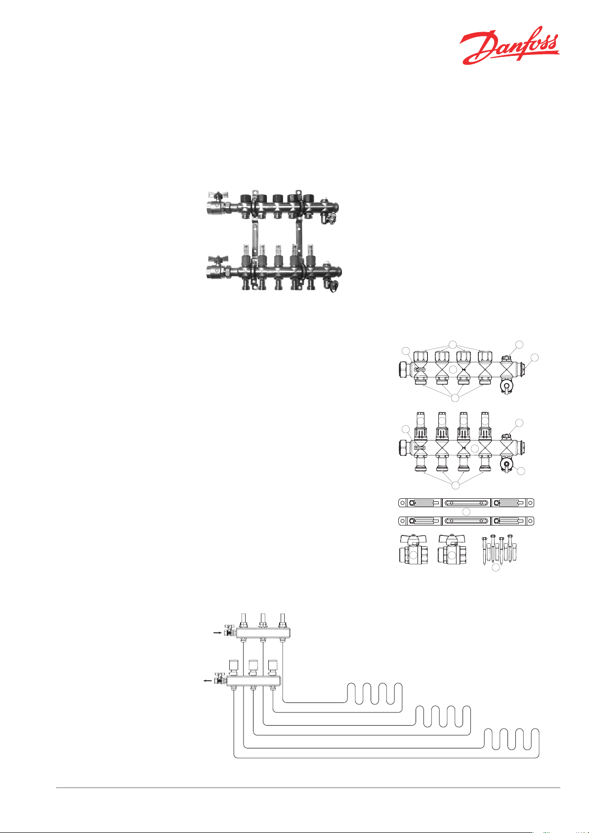
FBH Floor Heating Manifold
Application
The FBH floor heating manifold is used for controlling the water flow in floor heating systems.
Each string of the floor heating system is connected to the manifold, thus making it possible to
control water flow or heat supply for each room
individually.
The FBH range includes manifolds from 2 to 12
outlets.
FBH floor heating manifolds are supplied with all
necessary parts included:
1 supply manifold with flowmeter and possi-
▪
bility for individual shut-off of each circuit
1 return manifold
▪
2 ball valves
▪
2 brackets with screws and plugs
▪
The manifold valves can be controlled electronically by TWA-K thermal actuators or act as selfacting units by means of remote temperature adjusters, either by using CF2 or wired system.
Scope of Delivery
1.
Manifold body, stainless steel
2. Air-vent valve
3.
Cap on regulation valve M30x1.5 mm
4. 1” plug
5. Euro cone
6. Drain valve
7. Brackets
8. Flowmeter
9. Euro cone
10. Flow mark
11. Fastener set
12. 1” ball valves, 2 pcs., incl. flat packing
System Layout
Danfoss Heating Solutions VDUDR302 © Danfoss 08/2012 1
Data Sheet FBH Floor Heating Manifold
Ordering
Product Description Type/Size Code no.
FBH Manifold 2+2, stainless steel FBH-2F 088X0302
FBH Manifold 3+3, stainless steel FBH-3F 088X0303
FBH Manifold 4+4, stainless steel FBH-4F 088X0304
FBH Manifold 5+5, stainless steel FBH-5F 088X0305
FBH Manifold 6+6, stainless steel FBH-6F 088X0306
FBH Manifold 7+7, stainless steel FBH-7F 088X0307
FBH Manifold 8+8, stainless steel FBH-8F 088X0308
FBH Manifold 9+9, stainless steel FBH-9F 088X0309
FBH Manifold 10+10, stainless steel FBH-10F 088X0310
FBH Manifold 11+11, stainless steel FBH-11F 088X0311
FBH Manifold 12+12, stainless steel FBH-12F 088X0312
Thermal actuator - 24 V - NC TWA-K 088H3140
Thermal actuator - 230 V - NC TWA-K 088H3142
12x2 mm 013G4152
Compression fittings for PEX tubing in accordance with ISO 15875.
Max working pressure: 6 bar
▪
Test pressure: 10 bar
▪
Max flow temperature: 95 °C
▪
G ¾” internal thread
▪
Max flow temperature given by the tube
manufacturer must not be exceeded.
Compression fittings also suitable for
PERT tubing in accordance with ISO
15875.
13x2 mm 013G4153
14x2 mm 013G4154
15x2.5 mm 013G4155
16x 1.5 mm 013G4157
16x2 mm 013G4156
16x2.2 mm 013G4163
17x2 mm 013G4162
18x2 mm 013G4158
18x2.5 mm 013G4159
20x2 mm 013G4160
20x2.25 mm
20x2.5 mm 013G4161
013G4093
Compression fittings for ALUPEX tubing.
Max working pressure: 6 bar
▪
Test pressure: 10 bar
▪
Max flow temperature: 95 °C
▪
G ¾” internal thread
▪
Max flow temperature given by the tube
manufacturer must not be exceeded.
Compression fittings also suitable for
PERT/ALU/PERT tubing.
Compression fittings for STEEL and COPPER tubing.
Max working pressure: 6 bar
▪
Test pressure: 10 bar
▪
Max flow temperature: 120 °C
▪
G ¾” internal thread
▪
12x2 mm 013G4182
14x2 mm 013G4184
15x2.5 mm 013G4185
16x2 mm
16x2.25 mm 013G4187
18x2 mm 013G4188
20x2 mm 013G4190
20x2.25 mm
20x2.5 mm 013G4191
10 mm 013G4120
12 mm 013G4122
14 mm 013G4124
15 mm 013G4125
16 mm 013G4126
18 mm 013G4128
013G4186
013G4093
2 VDUDR302 © Danfoss 08/2012 Danfoss Heating Solutions

Q (l/h) =
50 W/m2 x 25 m
2
5°C x 1.16
= 216 l/h
Q (l/h) =
50 W/m2 x 15 m
2
5°C x 1.16
= 129 l/h
10 20 30 40 50 70 100 200 300 400 500 700 1000
1
2
3
4
5
6
8
20
30
40
50
600,6
0,5
0,4
0,3
0,2
0,1
0,08
0,06
0,05
0,04
0,03
0,02
0,01
10
p
p
Q [l/h]
[kPa]
[bar]
0,1
0,2
0,3
0,4
0,5
0,6
0,8
1
2
3
4
5
6
p
[mWg]
75
80
100
8
10
0,8
1
2
2
½ ½
3
3
4
Max
½
4
Data Sheet FBH Floor Heating Manifold
Capacity/Commissioning
The pre-setting of the manifold valves determines the flow in the floor heating tubes and
is therefore an important factor for obtaining
optimal hydraulic balance in the system.
A correct hydraulic balance is important if opti-
mal comfort shall be achieved with a minimum of
energy consumption and is easily carried out following the example shown below.
Example
Room 1 1 Determine longest tube/largest room 25 m²
2 Desired cooling (ΔT) 5°C (typical)
3 Determine heat requirement for the room 50 W/m²
4 Conversion factor 1.16
5 Calculation of flow for the room
Room 2 6 Determine area for the next room 15 m²
Calculation of flow for the room (ΔT and
7
heat requirement is assumed identical for
the rooms in this case)
FBH manifold with TWA-K
Presetting with TWA-K actuators on the supply
manifold can be carried out by opening the regulation valve by turning fully to open. Then adjust
each flow meter to obtain flow as calculated (see
example).
If the right flow cannot be obtained, the
▪
pump must be replaced with a larger one.
Start balancing with fully open the flow me-
▪
ter for circuit with the longest pipe length.
Next open flow meter for the circuit with
second longest pipe length, until wanted
flow is indicated in flow meter and so on.
When all circuits are done, go back to the
Close all flow meters.
▪
Fully open all circuits, starting with the lon-
▪
gest pipe length, then the second longest
etc.
▪
first and adjust for wear to wanted flow.
The pressure drop is calculated as sum of: ΔPpipe (longest circuit) + ΔP flow manifold.
Pressure loss / flow manifold set
(Turns - opening flow meter)
Danfoss Heating Solutions VDUDR302 © Danfoss 08/2012 3

50
L1
6732
200
52
Data Sheet FBH Floor Heating Manifold
Design
Operation Conditions
Dimensions
Supply manifold with flowmeter
Description Material
1. Sightglass Heat resistant plastic
2. Flowmeter nut Plastic
3. Adjusting cap Plastic
4. Supply manifold body St
5. O-rings EPDM
6. Connection nipple Brass
Max differential pressure: 0.6 bar
Max working pressure: Manifold with flowmeter 6 bar
Max test pressure: Manifold with flowmeter 10 bar
Max flow temperature: 90 °C
ainless st
eel
Type 2+2 3+3 4+4 5+5 6+6 7+7 8+8 9+9 10+10 11+11 12+12
L1 (mm) 192 242 292 342 392 442 492 542 592 642 692
Danfoss A/S
Heating Solutions
Haarupvaenget 11
8600 Silkeborg
Denmark
Phone:+45 7488 8000
Fax: +45 7488 8100
Email: heating.solutions@danfoss.com
www.heating.danfoss.com
Danfoss can accept no responsibility for possible errors in catalogues, brochures and other printed material. Danfoss reserves the right to alter its products without notice. This also applies to products
already on order provided that such alterations can be made without subsequential changes being necessary in specifications already agreed. All trademarks in this material are property of the respective
companies. Danfoss Heating Solutions and the Danfoss Heating Solutions logotype are trademarks of Danfoss A/S. All rights reserved.
4 VDUDR302 © Danfoss 08/2012 Danfoss Heating Solutions
 Loading...