

Page 1
User Manual
PLUS+1® GUIDE Software
PLUS+1® Function Block Library—Fault
Manager
www.danfoss.com
Page 2

User Manual
PLUS+1® Function Block Library—Fault Manager
Revision history Table of revisions
Date Changed Rev
September 2019 Updated book number 0103
June 2019 Added Service Tool screen for Standard license 0102
May 2019 First edition 0101
2 | © Danfoss | September 2019 AQ316177216676en-000103
Page 3

User Manual
PLUS+1® Function Block Library—Fault Manager
Contents
Fault Manager Overview
Modular System Design.................................................................................................................................................................4
Design, Build, and Add the Fault Management Features to an Application
Before You Begin.............................................................................................................................................................................. 5
Add Fault Management to Your Application.........................................................................................................................5
Determine the Fault Manager Features to Create................................................................................................................5
Complete the Fault-Definition Spreadsheet.......................................................................................................................... 5
Defining Fault Severity Levels................................................................................................................................................ 6
Adding and Moving Spreadsheet Columns...................................................................................................................... 6
Make Fault Connections in the Function Block.....................................................................................................................7
Fault_Mgr_Std Function Block
Inputs....................................................................................................................................................................................................8
Outputs................................................................................................................................................................................................ 8
Fault_Clock Function Block...........................................................................................................................................................8
Inputs...............................................................................................................................................................................................9
Outputs...........................................................................................................................................................................................9
FltMgr_IntFace Function Block....................................................................................................................................................9
Expand Space for Fault History.............................................................................................................................................. 9
Rcd_Set........................................................................................................................................................................................... 9
Change Namespace Value............................................................................................................................................... 10
Fault Manager Service Tool Screens
Configure the Service Tool Screens.........................................................................................................................................11
Install the .p1d File................................................................................................................................................................... 12
Configure the FaultDescriptions.js file..............................................................................................................................12
Launch the Fault Monitor...................................................................................................................................................... 12
Example Fault Manager Service Tool Screen with Professional License....................................................................13
Example Fault Manager Service Tool Screen with Standard License..........................................................................14
Use the Detailed Fault Manager Service Tool Screen.......................................................................................................14
Fault_DM_1_2_ Iface Function Block
Inputs..................................................................................................................................................................................................15
Outputs..............................................................................................................................................................................................15
©
Danfoss | September 2019 AQ316177216676en-000103 | 3
Page 4

User Manual
PLUS+1® Function Block Library—Fault Manager
Fault Manager Overview
The Fault Manager allows you to design and develop fault management functions for machine
applications in an simple, iterative manner.
Your input to a macro-enabled spreadsheet is used to generate all of the PLUS+1® GUIDE interface files
that are needed to monitor each connected, potential fault source in a machine.
The Fault Manager also generates an interface file for service tool screens, making it easy to display
current faults, as well as the history of previous faults and how often they occur.
The Fault Manager consists of components that are available as an SDL library in PLUS+1® GUIDE. To add
fault management features to an application, drag the desired components onto the GUIDE canvas and
make a simple connection.
You can successfully compile your application at this point, even before connecting any components that
might generate errors. This flexibility lets you define the application's faults iteratively, over time. During
development, you may complete or tweak information in the fault-definition spreadsheet then re-run the
macro. All the new or updated interface files are then created for the application.
Modular System Design
The Fault Manager Library contains components that can be used to add diagnostic functions to
applications on an as-needed basis.
The modular design of the Fault Manager lets your application collect diagnostic data from services such
as CANopen and J1939.
The Fault Manager Standard function block collects data that can be used for Diagnostic Messages (DM)
DM1 and DM2.
The assembled Fault Management system is limited only by the memory available in the controller. The
Fault Manager Standard option can handle up to 3375 individual faults, including faults of the Fault
Manager itself.
4 | © Danfoss | September 2019 AQ316177216676en-000103
Page 5

User Manual
PLUS+1® Function Block Library—Fault Manager
Design, Build, and Add the Fault Management Features to an Application
Determine the fault management features to add to the application, complete the fault-definition
spreadsheet, and connect faults to the Fault input bus of the Fault Manager block in the PLUS+1® GUIDE
application.
Before You Begin
Before you add Fault Manager components to your application, make sure you have the required
software tools installed.
Ensure these software programs and libraries are installed on the computer where you develop
applications:
•
PLUS+1® GUIDE version 10.1 or later.
•
PLUS+1® Service Tool version 10.1 or later.
•
Download and install the Fault Manager library in PLUS+1® GUIDE.
•
Microsoft Excel.
Add Fault Management to Your Application
Open the application that you want to add fault management to, then drag and drop the desired Fault
Management components onto the development canvas.
You can add the desired Fault Manager function block options to your application, even before any
potential fault sources are connected.
1. Select the Function tab in the right panel of PLUS+1® GUIDE.
2. Expand the Fault Manager library, then select the Fault Manager block you want to use in your
application. For Fault Manager Standard, select Fault_Mgr_Std.
3. Drag the function block onto the PLUS+1® GUIDE canvas.
4. In the window that appears, click Yes to confirm that you want to add the interface files and the
spreadsheet to your application.
The interface files and spreadsheet are added to the Project Manager panel.
5. Connect the two block inputs HstClear and HstErase to False Constant components. Later, you can
use these inputs to add optional external control over history memory.
You can compile the application successfully at this point. Or, if desired, you can complete the faultdefinition spreadsheet with as much information as is ready, gradually adding fault management
functions to the application.
Determine the Fault Manager Features to Create
Design the fault management functions wanted in the application, such as the types of fault information
to collect and how this information is used.
This work helps you complete the macro-enabled spreadsheet, where you will enter:
•
The variable name for the fault in PLUS+1® GUIDE.
•
The fault description, for use in a service tool application.
•
Number of severity levels required and the severity level of each fault. Severity level zero is the
highest level.
•
Whether or not the fault should be latching.
•
SPN/FMI numbers for each fault if DM1 and DM2 are used.
•
Do not enter information into the DM4 column.
Complete the Fault-Definition Spreadsheet
Complete the fault-definition spreadsheet with the fault features desired, then run the macro to generate
the interface files that make fault management available in the application.
When completing the fault-definition spreadsheet, follow these rules and recommendations:
©
Danfoss | September 2019 AQ316177216676en-000103 | 5
Page 6

User Manual
PLUS+1® Function Block Library—Fault Manager
Design, Build, and Add the Fault Management Features to an Application
•
When entering PLUS+1® GUIDE Variable Names, ensure the first character is a lowercase letter (a-z)
and the last character is either a lowercase letter or number (0-9). This is a limitation of the underlying
language structure. If you use an uppercase letter in these locations, the uppercase letter is changed
to lowercase when you click BUILD PROJECT in order to be compatible with PLUS+1® GUIDE.
You are not required to complete all the fields on the spreadsheet. However, the recommended
minimum fields to complete for each fault are:
•
PLUS+1® GUIDE Variable Name
•
Short Fault Description
•
Indicate if the fault is latched. Define most faults as latching, except those you want to clear when the
fault is removed, such as calibration faults.
•
Fault Severity Level. See Defining Fault Severity Levels for more information.
If you are just trying to learn more about the Fault Manager, note that only one column of the
spreadsheet – the first one, GUIDE Variable Name – must be completed before you run the BUILD
PROJECT macro.
After completing the only required column, connect the faults to the function block's Fault input bus in
PLUS+1® GUIDE, then compile the application. Using this approach, all faults are then assumed to be nonlatching and have maximum (zero) severity. Also, no descriptions are available for the Service Tool.
If SPN and FMI are left blank, zeros are used as inputs.
1. Open the spreadsheet: by double-clicking EnterFaultDefinitions.xlsm in the Documents folder in
the Project Manager panel.
Complete each column of the spreadsheet with the desired information.
Only one column is mandatory: GUIDE Variable Name.
a) From the Project Manager tab in PLUS+1® GUIDE, open the Documents folder.
b) Double click on the EnterFaultDefinitions.xlsm file to open it in Excel.
2. Click BUILD PROJECT.
3. In PLUS+1® GUIDE, accept the prompts to overwrite the interface files.
Interface files are created, as are the faults that are to be connected in the application.
Defining Fault Severity Levels
Follow these recommendations when defining the fault severity levels.
Severity level 0 is the highest level in this system.
To define how many severity levels are needed, set the severity levels at the extreme ends with just two
faults. A system is created with that many levels.
For example, if you set one fault to 0 and another to 3, a four-level severity system is created, leaving the
in-between levels empty internally, ready for use. It is suggested that you fully populate the severity
levels when possible to avoid unused and forgotten levels.
To revise the layout:
1. Change spreadsheet entries.
2. Click BUILD PROJECT to re-run the macro.
Adding and Moving Spreadsheet Columns
You can move columns in the spreadsheet as well as add user-defined columns to the spreadsheet.
Use the usual Excel steps to add or move columns. If you are moving a column, make sure to highlight an
entire column and not just the data within the column before the move. Moving data to a column where
that data is not intended to be used may result in data type mismatch errors and incorrect operation of
the Fault Manager.
6 | © Danfoss | September 2019 AQ316177216676en-000103
Page 7

User Manual
PLUS+1® Function Block Library—Fault Manager
Design, Build, and Add the Fault Management Features to an Application
Make Fault Connections in the Function Block
After running the spreadsheet macro, faults and the interface files to them are created.
Connect faults to the Fault Manager function block on the PLUS+1® GUIDE canvas.
All faults are assumed to be Boolean types: either there is a fault or there is not a fault.
To apply conditions to faults, such as timing, or tripping of a fault when a certain condition is met, define
the conditions separately in the PLUS+1® GUIDE application, somewhere before the function block's code
is run.
1. Perform one of the following to make room in PLUS+1® GUIDE so all faults can be connected:
Extend the Faults input bus on the Fault_Mgr_Std function block.
•
Route the Faults input bus to a page that is different than the page where the function block is.
•
2. Attach the fault Booleans to the Faults bus.
a) After building the project with the spreadsheet, each input variable name appears in the Connect
To Bus dialog pop-up, with the status of Undriven.
b) Double-click each variable as appropriate and connect it to the bus.
You can leave the Para input and the T-Max output disconnected.
•
Para is disconnected internally. You can use it to bring the Enable signal out for external use.
•
T_Max is the time of the last fault occurrence. It might be beneficial to use an external clock to
generate a new time at start up, a time that is not earlier than a time already recorded in history.
You must connect HstClear and HstErase.
•
If you are not using either, connect to False components.
•
HstClear clears previously active faults from history. Attach the block input to a false component if
the service tool controls this input.
•
HstErase erases all recorded faults and their occurrence times. If faults are latched when erase is
used, the faults are re-recorded in memory, along with a current time. Attach the block input to a
false component if the service tool controls this input.
©
Danfoss | September 2019 AQ316177216676en-000103 | 7
Page 8

User Manual
PLUS+1® Function Block Library—Fault Manager
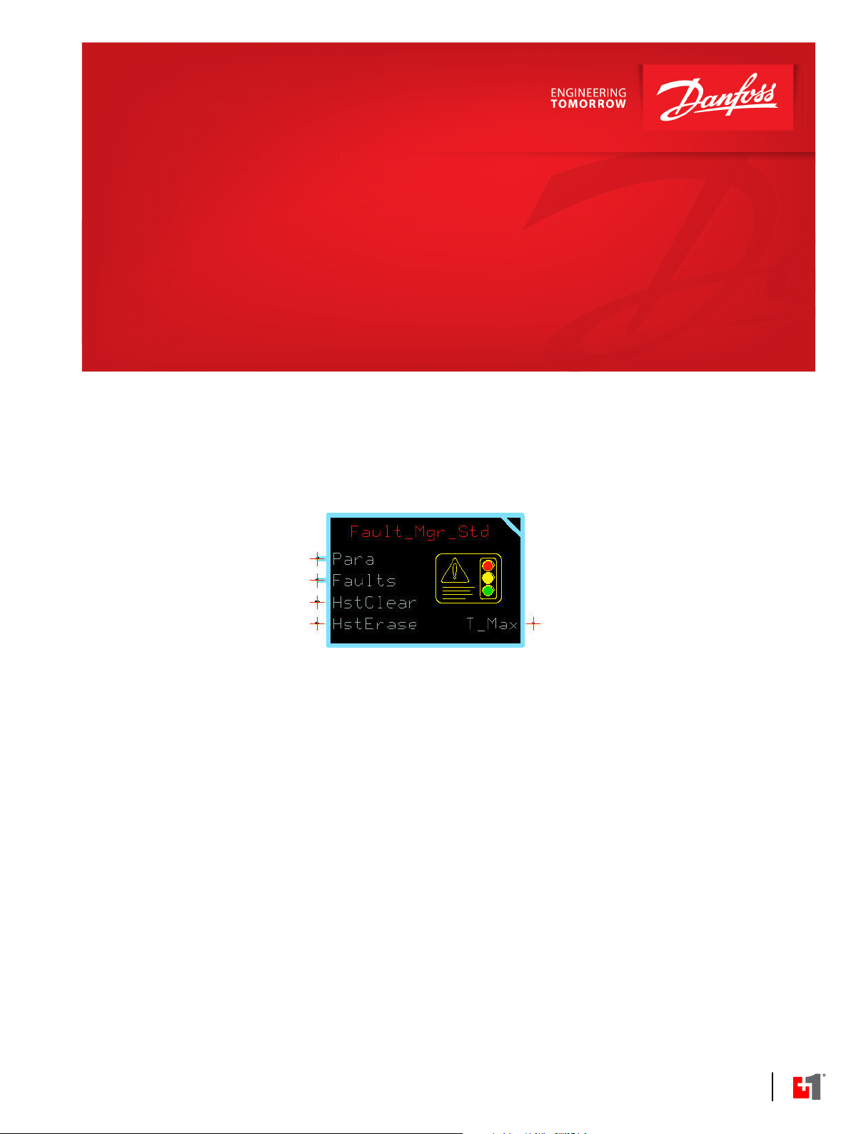
Fault_Mgr_Std Function Block
Use the Fault_Mgr_Std function block to monitor all connected fault sources for current and previous
activity.
Place the Fault_Mgr_Std function block at the top of the execution order so PLUS+1® GUIDE allocates
memory for the Fault Manager first. Doing so reduces the chance of memory shift.
The Fault_Mgr_Std has two child blocks:
•
Fault_Clock, which provides a time stamp of each occurrence of a fault.
•
FltMgr_IntFace, which can expand and control the memory used to store the history of fault
occurrences.
Each child block has its own inputs and outputs. Enter the Fault_Mgr_Std function block to see and use
these inputs and outputs.
Inputs
Inputs to the Fault_Mgr_Std function block are described.
Signal Type Range Description
Para
Faults BUS —— All fault signals that are defined.
HstClear
HstErase BOOL T/F Erase all faults from the history and their occurrence time from the history.
BUS
T/F Set parameter values or replace values with signals routed from the application through the Para bus.
To successfully compile the application, connect all variable names that are listed in the spreadsheet to
this bus.
BOOL T/F Clear the previously active faults from the history.
T: Clear previously active faults.
F: Do not clear faults.
Active or latched fault re-load.
T: Erase all previous faults.
F: Do not erase all previous faults.
Outputs
The outputs of the Fault_Mgr_Std standard function block are described.
Signal Type Range Description
T_Max U32 0-4294967295 Maximum time last recorded in any non-volatile memory for use in an optional, external clock.
Fault_Clock Function Block
The Fault_Clock function block is a sub-block of the Fault Manager.
It saves a time stamp for each new fault that occurs.
If desired, you can use your own clock. See the connection details that follow for more information.
8 | © Danfoss | September 2019 AQ316177216676en-000103
Page 9

User Manual
PLUS+1® Function Block Library—Fault Manager
Fault_Mgr_Std Function Block
Inputs Inputs to the Fault_Clock function block are described.
Signal Type Range Description
Fault_Clock Child block —— The Fault_Clock controls the maximum amount of time used to store fault
occurrences in any history location of memory.
T-Max U16 0-4294967295 Maximum time stored in any history location at power up. Active one frame only,
otherwise 0.
LoopTm U16 0-65535 Processing time of one program loop.
Unit: ms.
Outputs The outputs of the Fault_Clock function block are described.
Signal Type Range Description
Hours U32 0-4294967295 Current running time of clock.
Resolution: 0.36 seconds.
Unit: 0.0001 hours.
FltMgr_IntFace Function Block
The FltMgr_IntFace function block controls the memory that can be used to store fault history.
This function block is a sub-block of the Fault Manager.
The Fault Manager Standard module has space to store up to 16 fault occurrences and their data. If 16
different and concurrent faults occur, the 16th storage space in Fault Management’s history (stored in NV
memory) is replaced by the Fault Manager’s own History Full fault
If the same fault occurs 16 times, it takes up only one space and stores its first and last occurrence times.
It does not require 16 spaces.
The limit of 16 spaces is used to preserve non-volatile memory for the application. This memory is
allotted exclusively to fault history storage. This memory is not available to the application.
Expand Space for Fault History
You can expand space for Fault Manager history. To do so, enter the Fault_Mgr_Std function block, then
enter the FltMgr_IntFace sub-block.
This accesses the History Memory Size page, where you add the required memory up to 64 spaces in
increments of 8 spaces. Use the Rcd_Set component to add the memory blocks.
•
Each memory block can store data from 8 active or previously active faults.
•
The maximum is 8 memory blocks that can store data from 64 active or past faults.
•
The default for the Flt_Mgr_Std is 2 memory blocks that can store data from 16 faults.
The maximum number of individual faults that can be allotted to an application is not limited by this
memory. Rather, the memory limits the number of different fault occurrences that are recorded in nonvolatile memory.
Rcd_Set
Use the Rcd_Set sub-block to define areas of memory where a history of fault occurrences can be stored.
To define up to 8 record sets:
1. Drag the desired number of Rcd_Set sub-blocks onto the History Memory Size page.
2. Place the blocks in the placeholders, left to right.
©
Danfoss | September 2019 AQ316177216676en-000103 | 9
Page 10

User Manual
PLUS+1® Function Block Library—Fault Manager
Fault_Mgr_Std Function Block
3. Connect the records sets in sequential order, that is connect Set_0 to Set_1, Set _1 to Set_2, and so
on.
4. Edit the Set_x namespace to match the record set number used.
5. Connect the last, right-most block to the Last connector.
Item Description
1
2
Change the namespace from Set_x to match the Rec_Set number. In this case, set the value to
Set_2.
Connect the last record set, Rcd_Set_2, to the Last connector.
Change Namespace Value
To successfully compile your application, change the namespace value for function blocks that are used
more than once in an application.
1. In the PLUS+1® GUIDE menu bar, click the Query/Change button.
2. Click on the function block whose namespace you want to set to a unique value.
The Edit Page window opens.
3. In the Edit Page window, enter a meaningful Namespace value.
Namespace values are case-sensitive.
•
To save controller memory, use a short namespace value.
•
4. Press Enter.
5. Repeat these steps to enter unique namespace values for other identical function blocks.
10 | © Danfoss | September 2019 AQ316177216676en-000103
Page 11
User Manual
PLUS+1® Function Block Library—Fault Manager
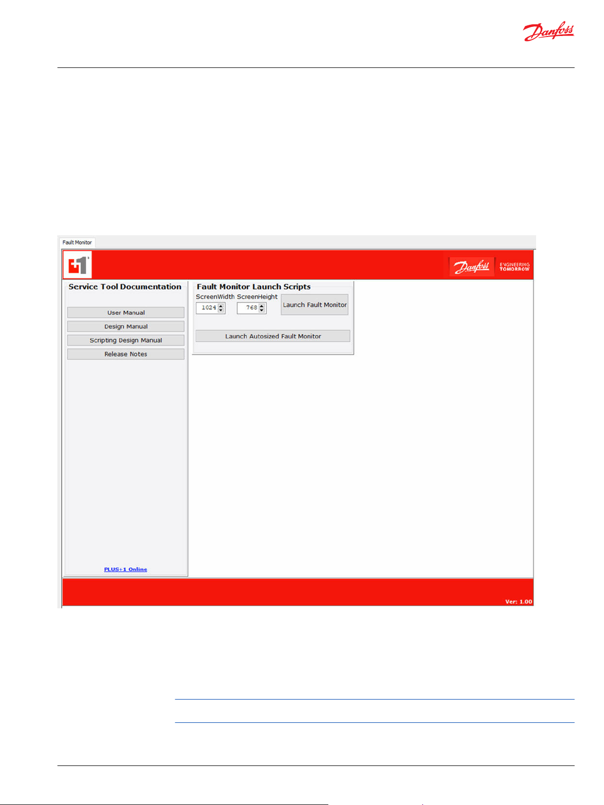
Fault Manager Service Tool Screens
A Service Tool Fault Monitor p1d interface file, ST_FaultMonitor.p1d, is included in the Fault Manager
library.
If you require a Service Tool screen, use this file to provide the Service Tool with all the interface
information it needs to display your faults and their conditions.
The service tool screen includes a Fault Monitor launch panel where you can launch a pop-up Service
Tool screen.
It also includes a list of Service Tool documents. Click the button that represents the document you want
to open.
An example screen follows.
Configure the Service Tool Screens
The service tool license helps determine what items appear on the service tool screen.
If you have a Professional service tool license, you can customize the fault names in the spreadsheet.
These custom fault names, as well as SPNs and FMIs, are displayed on the PLUS+1® Service Tool screen.
Additionally, severity levels are displayed as color-coded fault names.
A Professional add-on license to the PLUS+1® Service Tool enables these design features. This license is
Danfoss part number 11179527.
If you have a Standard service tool license, the fault names that appear on the screen default to generic
names. The names display as Fault 1, Fault 2 and so on, in the order that faults are listed in the
spreadsheet before the project is built.
©
Danfoss | September 2019 AQ316177216676en-000103 | 11
Page 12

User Manual
PLUS+1® Function Block Library—Fault Manager
Fault Manager Service Tool Screens
If you do not have the Professional add-on license to the PLUS+1® Service Tool, but rather the Standard
built-in license supplied with the tool, you can use service application files that contain scripts.
To configure service tool screens:
•
All users, regardless of the license file, must install the .p1d file.
•
To ensure customizations to the screen appear, users with the Professional service tool license must
also configure the FaultDescriptions.js file.
Install the .p1d File
Save the pre-made service tool file (Service Tool Fault Monitor.p1d ) to your hard drive to use in the PLUS
+1® Service Tool.
All users, whether using a Standard or Professional service tool license, must install the .p1d file. To install
it:
1. In the Fault Manager Library folder, right-click on the Service Tool Fault Monitor.p1d file and select
Save As....
2. Navigate to the area where you want to store the file and click Save.
3. Open the service tool.
4. To open the .p1d file, select File, Open.
Configure the FaultDescriptions.js file
Users with a Professional service tool license can configure the FaultDescriptions.js file to ensure
customizations appear on the service tool screen.
1. Ensure you are in Design View. In the PLUS+1® Service Tool, from the View menu, select Design View.
2. Click the plus + icon next to the Resources folder to expand it.
3. Right-click on the FaultDescriptions.js file and select Delete.
4. Replace the file that you just deleted with the FaultDescriptions.js file that was created when you
used the spreadsheet to build your project
a) Right-click on the Resources folder and select Add Resource File....
b) Navigate to the location where the interface file for the service tool is stored. This location is in the
main project folder where all PLUS+1® GUIDE files are stored.
c) Find the FaultDescriptions.js file, which was created when you clicked BUILD PROJECT on the
spreadsheet.
d) Click Open to place the file in the Resources folder.
5. Load the new file into the project file for the service tool.
a) Expand the Scripts folder.
b) Expand ScriptInterface.
c) Right-click on ScriptFunction and select Reload.
The System Navigator panel grays out while the new FaultDescriptions.js file is added to the
project file.
Launch the Fault Monitor
You can open the Fault Monitor screen as a custom-size screen or as an auto-sized screen.
To start the Fault Monitor:
12 | © Danfoss | September 2019 AQ316177216676en-000103
Page 13

User Manual
PLUS+1® Function Block Library—Fault Manager
Fault Manager Service Tool Screens
1. Go to the bottom of the System Navigator panel.
2. Perform one of the following:
To specify a size for the screen, enter the desired values in the Screen Width and Screen Height
•
fields, then click Launch Fault Monitor.
To open a non-unique sized screen, click Launch Autosized Fault Monitor.
•
Example Fault Manager Service Tool Screen with Professional License
Use the service tool screen to determine the status of faults and how often they have occurred.
If a Professional service tool license is used, Fault Condition descriptions that appear on the service tool
screen come directly from the Short Fault Descriptions entered into the spreadsheet, as do the SPN and
FMI.
On the service tool screen, the background color of the Fault Condition column indicates the severity
level of the fault. To determine the key to the color codes, click the information button at the top of the
screen.
The Fault Condition color key dialog box opens.
Fault occurrence times are also displayed on the service tool screen, both the first time a fault became
active and the last time. Faults that have only one occurrence show the first and last times as the same.
©
Danfoss | September 2019 AQ316177216676en-000103 | 13
Page 14

User Manual
PLUS+1® Function Block Library—Fault Manager
Fault Manager Service Tool Screens
Example Fault Manager Service Tool Screen with Standard License
If you a standard license, the service tool screen looks generic and the fault condition color key is
different.
To determine the key to the color codes for faults, click the information button at the top of the screen.
The Fault Condition color key dialog box opens.
Use the Detailed Fault Manager Service Tool Screen
The service tool screen can be used to clear recorded faults, erase faults and reset the clock that uses a
time stamp on each fault occurrence.
To clear faults:
•
To clear previously active faults, click Clear Inactive.
•
To clear latched faults:
1. Turn the machine's controller off and on. Active faults then become inactive.
2. Click Clear Inactive
•
To erase all faults, click Erase All.
To select the ECU whose faults are displayed, select the ECU from the ECU Selection List menu.
14 | © Danfoss | September 2019 AQ316177216676en-000103
Page 15
User Manual
PLUS+1® Function Block Library—Fault Manager
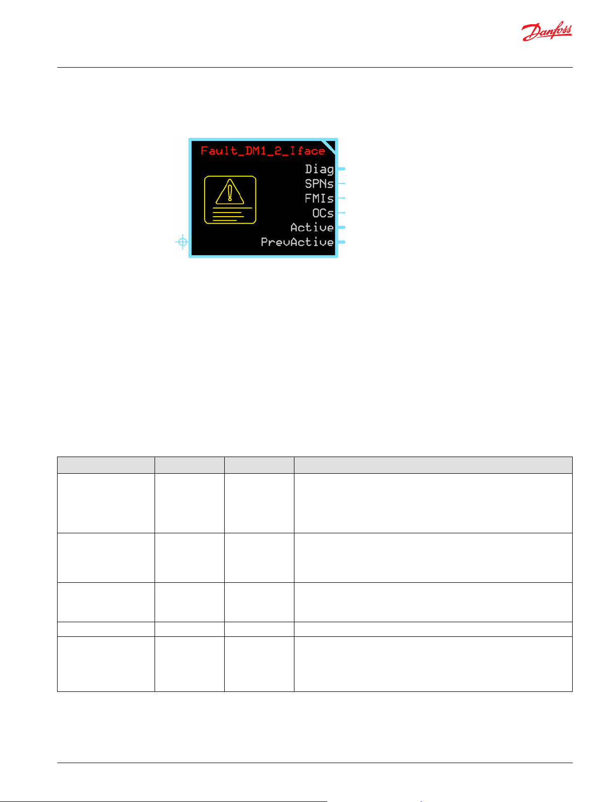
Fault_DM_1_2_ Iface Function Block
The Fault_DM_1_2_ Iface function block assembles the Fault Manager's DM1 and DM2 data so the data
can be connected directly to function blocks in the J1939 function block library.
The Fault_DM_1_2_ Iface is a sub-block of the Fault Manager. It uses compiled code packages (CCPs) to
collect the Fault Manager's DM1/DM2 data (SPNs, FMIs, Occurrence Counts, Active/Previously Active
faults). It then assembles this data so it can be input to a J1939 function block.
This approach allows the function block to be placed anywhere in an application, which simplifies project
layout.
Inputs
The Fault_DM1_2_Iface function block does not have inputs.
This function block uses compiled code packages (CCPs) to obtain fault information from the
Flt_Mgr_Std function block's history modules.
Outputs
The outputs of the Fault_DM1_2_Iface function block are described.
Signal Type Range Description
SPNs U32 ARRAY 0 – 0x7FFFF Suspect parameter number, which can be directly input to a function block in the
J1939 library.
The function block formats the information from the Fault_Mgr_Std memory.
The maximum width of the SPN is 19 bits.
•
The range is 0-0x7FFFF.
•
FMIs U8 ARRAY 0 – 0x1F Failure mode identifier, formatted by the function block, to be input directly to a
J1939 function block.
The maximum width of the FMI is 5 bits.
•
The range is 0-0x7FFFF.
•
OCs U8 ARRAY 0 – 0xFF Occurrence count of a fault.
The maximum width of the OC is 8 bits.
•
The range is 0-0x7FFFF.
•
Active BUS
.Active1-.Active8 U32 Bit 0 – Bit 31 Active fault.
Each bit in the word represents an individual fault, for a maximum of 256
possible faults.
Bit 0 of active 1 matches SPN/FMI/OC array element 0.
Bit 31 of active 8 matches SPN/FMI/OC array element 255.
©
Danfoss | September 2019 AQ316177216676en-000103 | 15
Page 16

User Manual
PLUS+1® Function Block Library—Fault Manager
Fault_DM_1_2_ Iface Function Block
Signal Type Range Description
PrevActive BUS
.PrevActive1-.PreActive8 U32 Bit 0 – Bit 31 Previously active faults.
Each bit in the previously active word represents a fault, for a maximum of 256
faults.
Bit 0 of previously active 1 matches SPN/FMI/OC array element 0.
Bit 31 of previously active 8 matches SPN/FMI/OC array element 255.
16 | © Danfoss | September 2019 AQ316177216676en-000103
Page 17

Danfoss
Power Solutions GmbH & Co. OHG
Krokamp 35
D-24539 Neumünster, Germany
Phone: +49 4321 871 0
Danfoss
Power Solutions ApS
Nordborgvej 81
DK-6430 Nordborg, Denmark
Phone: +45 7488 2222
Danfoss
Power Solutions (US) Company
2800 East 13th Street
Ames, IA 50010, USA
Phone: +1 515 239 6000
Danfoss
Power Solutions Trading
(Shanghai) Co., Ltd.
Building #22, No. 1000 Jin Hai Rd
Jin Qiao, Pudong New District
Shanghai, China 201206
Phone: +86 21 3418 5200
Products we offer:
Hydro-Gear
www.hydro-gear.com
Daikin-Sauer-Danfoss
www.daikin-sauer-danfoss.com
DCV directional control
•
valves
Electric converters
•
Electric machines
•
Electric motors
•
Hydrostatic motors
•
Hydrostatic pumps
•
Orbital motors
•
PLUS+1® controllers
•
PLUS+1® displays
•
PLUS+1® joysticks and
•
pedals
PLUS+1® operator
•
interfaces
PLUS+1® sensors
•
PLUS+1® software
•
PLUS+1® software services,
•
support and training
Position controls and
•
sensors
PVG proportional valves
•
Steering components and
•
systems
Telematics
•
Danfoss Power Solutions is a global manufacturer and supplier of high-quality hydraulic and
electric components. We specialize in providing state-of-the-art technology and solutions
that excel in the harsh operating conditions of the mobile off-highway market as well as the
marine sector. Building on our extensive applications expertise, we work closely with you to
ensure exceptional performance for a broad range of applications. We help you and other
customers around the world speed up system development, reduce costs and bring vehicles
and vessels to market faster.
Danfoss Power Solutions – your strongest partner in mobile hydraulics and mobile
electrification.
Go to www.danfoss.com for further product information.
We offer you expert worldwide support for ensuring the best possible solutions for
outstanding performance. And with an extensive network of Global Service Partners, we also
provide you with comprehensive global service for all of our components.
Local address:
Danfoss can accept no responsibility for possible errors in catalogues, brochures and other printed material. Danfoss reserves the right to alter its products without notice. This also applies to products
already on order provided that such alterations can be made without subsequent changes being necessary in specifications already agreed.
All trademarks in this material are property of the respective companies. Danfoss and the Danfoss logotype are trademarks of Danfoss A/S. All rights reserved.
©
Danfoss | September 2019 AQ316177216676en-000103
 Loading...