

Page 1

Installation Guide
Expansion Module
for Danfoss Icon™ Master
© Danfoss | FEC | 2018.12 | 1AN28953970588601-000201 | VIMDE20F | 088N2100
Page 2

Installation Guide Expansion Module for Danfoss Icon™ Master
2 | © Danfoss | FEC | 2018.12 VIMDE20F / 088N2100
Page 3

Installation Guide Expansion Module for Danfoss Icon™ Master
Content
Expansion Module for Danfoss Icon™ Master .................................................... 4
Expansion Module for Danfoss Icon™ Master ...................................................24
Expansion Module for Danfoss Icon™ Master ...................................................44
Expansion Module for Danfoss Icon™ Master ...................................................64
Expansion Module for Danfoss Icon™ Master ...................................................84
Expansion Module for Danfoss Icon™ Master ..................................................104
Expansion Module for Danfoss Icon™ Master ..................................................124
Expansion Module for Danfoss Icon™ Master ..................................................144
Expansion Module for Danfoss Icon™ Master ..................................................164
Expansion Module for Danfoss Icon™ Master ..................................................184
Expansion Module for Danfoss Icon™ Master ..................................................204
Expansion Module for Danfoss Icon™ Master ..................................................224
Expansion Module for Danfoss Icon™ Master ..................................................244
Expansion Module for Danfoss Icon™ Master ..................................................264
Expansion Module for Danfoss Icon™ Master ..................................................284
GB
DE
FR
IT
NL
DK
SE
NO
IS
FI
CN
LT
PL
TR
UA
Expansion Module for Danfoss Icon™ Master ..................................................304
© Danfoss | FEC | 2018.12 | 3VIMDE20F / 088N2100
RU
Page 4
Installation Guide Expansion Module for Danfoss Icon™ Master
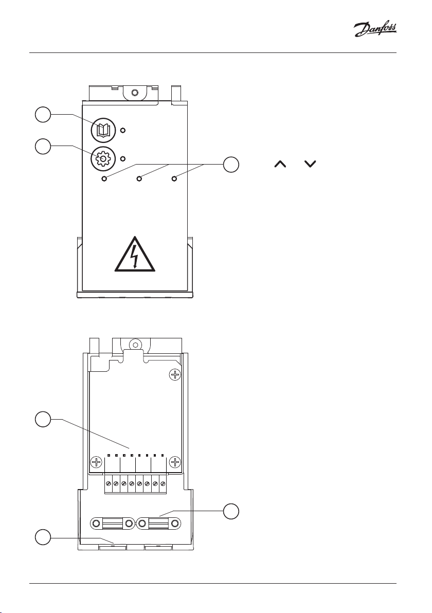
Perform wirring according to electrical
diagram, then insert the Expansion
1
APPLICATION
2
IN 1
SETTINGS
IN 2 IN 3
3
Module into the Danfoss Icon™ Master
Controller for extra features.
1. Use this key to choose application.
2. Use the key to set application
3. LED’s indicate the state of the inputs
4. Terminals for connection of various
5. Cable strain relief.
6. Break away for wiring /cables.
Press application key and then use
and to choose application
1-11 and confirm with “OK”. See
applications drawings to help you
choose the correct application.
specific settings. See in application
description which settings are
available for the chosen application.
1 to 3. See application description
for the specific application.
wiring /external devices.
4
IN 3 IN 2 IN 1
PWR3
PT
24
1000
VDC
5
6
4 | © Danfoss | FEC | 2018.12 VIMDE20F / 088N2100
Page 5
Installation Guide Expansion Module for Danfoss Icon™ Master
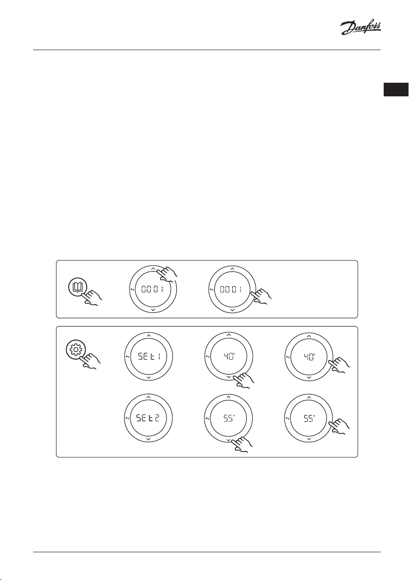
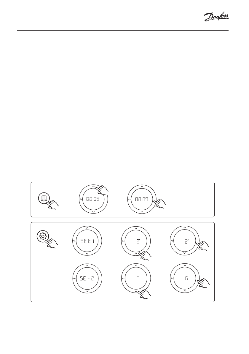
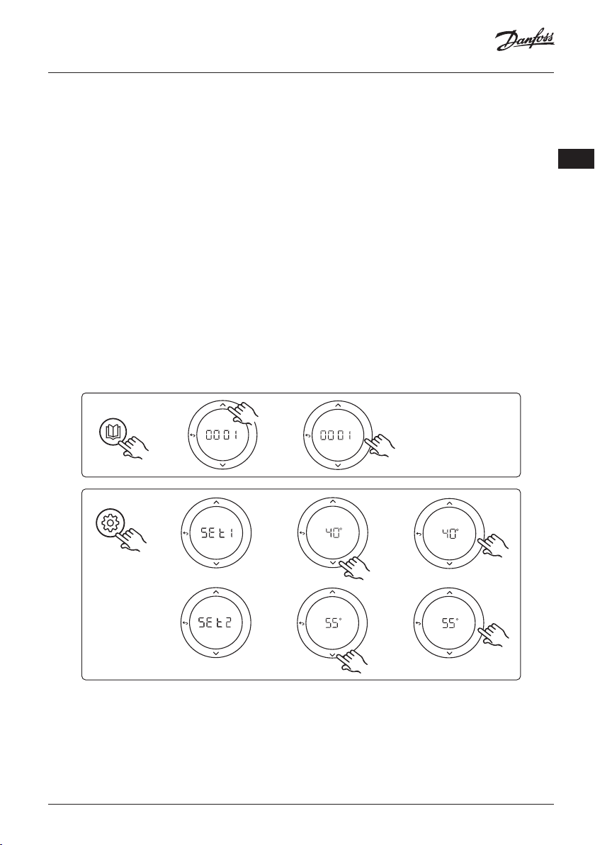
Application 0001: 2-pipe system, fixed supply temperature, electronically
controlled.
Optional: Global standby.
Application description
Floor heating system with electronic supply temperature control. The supply temperature is set to a fixed
value.
The system uses a PT1000 sensor to detect and control the supply temperature and is also used to ensure
that the temperature does not exceed the max. allowed temperature. If connected, the system will control
the circulation pump and the heat demand signal for e.g. a boiler or heat pump. The pump and heat
demand signal will be on when minimum 1 circuit has a heat demand. Output 1 must be used for TWA on
mixing shunt.
The Global standby is a potential free input that can be used to remotely put the system in Global away
mode e.g. via an external 3rd party GSM module. When global standby input is active, all rooms receive a 15
degree celcius setpoint.
Settings
“SET 1” = Set desired supply flow temperature [25-70°C]
“SET 2” = Set desired safety cut-off temperature [30-75°C]
Note: temperature must be higher than flow temperature.
GB
APPLICATION
SETTINGS
OK
OK
OK
OK
OK
OK
OK
OK
© Danfoss | FEC | 2018.12 | 5VIMDE20F / 088N2100
Page 6

Installation Guide Expansion Module for Danfoss Icon™ Master
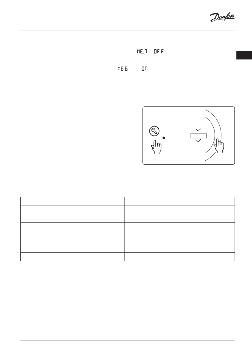
Application test function
Enter the “Test” menu via the installer key.
The Application test (APP test) is specific for each application. The test is split into steps to ensure that all components are installed correctly. Please follow the process.
Test steps
RUN
INSTALL
UNINSTALL
TEST
TEST NET
TEST APP
TEST FL
O
Step 1:1 Go to mixing shunt control valve actuator, and
verify that the valve opens fully (up to 3 minutes opening
time can be expected). After 5 minutes, the mixing shunt
valve actuator will close again.
During the 5 minute test period, the display on the Master
Controller will also show the measured supply flow temperature in the display.
Parts list
Pos. 1 088U0093-96 1 pc. Danfoss FHM-Cx Mixing shunt
Pos. 2 088U05XX / 088U06XX / 088U07XX 1 set Danfoss Manifold (types FHF or BasicPlus or SSM)
Pos. 3 NC: 088H3110 / NO: 088H3111 xx pcs. thermal actuator, 24 V TWA-A
Pos. 4 087B1165 1 pc. ESM-11 PT-1000 sensor
Pos. 5. NC: 088H3110 / NC: 193B2148 1 pc. thermal actuator, 24 V (types TWA-A or ABN-FBH)
OK
6 | © Danfoss | FEC | 2018.12 VIMDE20F / 088N2100
Page 7
Installation Guide Expansion Module for Danfoss Icon™ Master
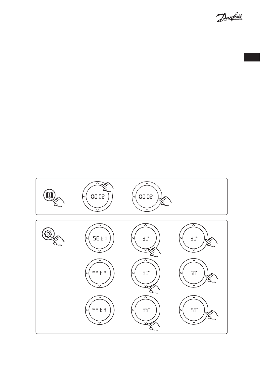
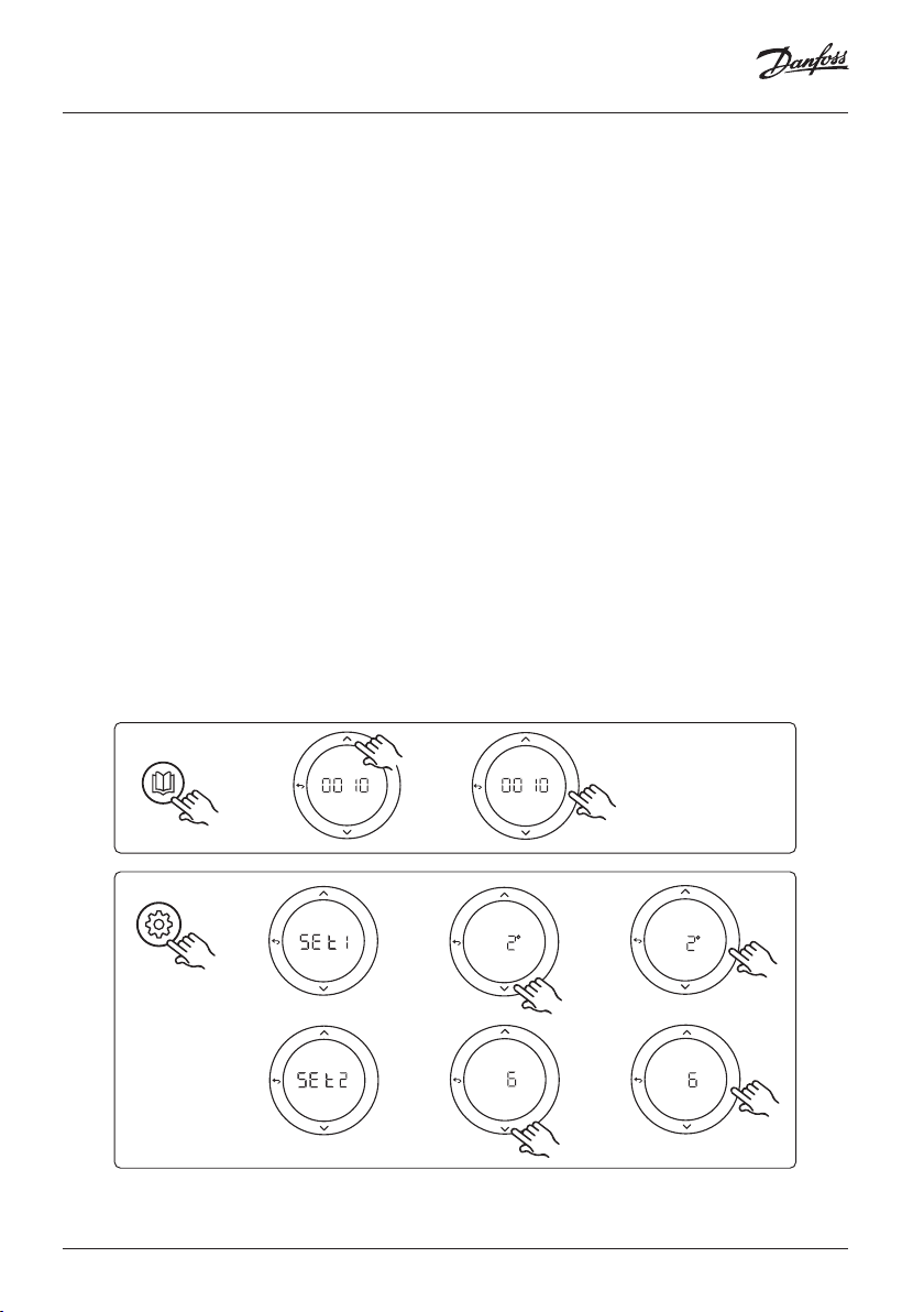
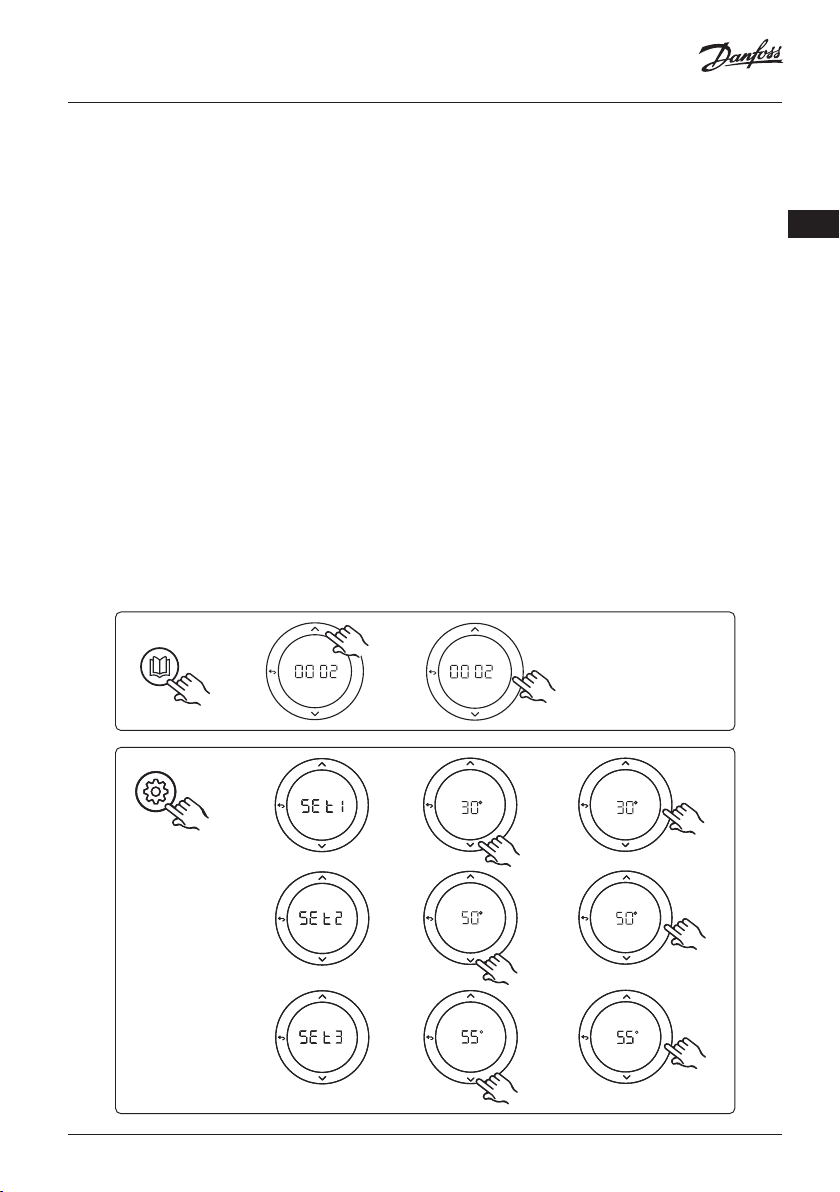
Application 0002: 2-pipe system with demand based supply temperature
control.
Optional: Global standby.
Application description
Floor heating system with electronic supply temperature control.
The demand based supply temperature is controlled depending on the heat demand from the rooms.
The system uses a PT1000 sensor to detect the supply temperature and is also used to ensure that the
temperature does not exceed the max. allowed temperature via a safety Tmax. If connected, the system
will control the circulation pump and the heat demand signal for e.g. a boiler or heat pump. The pump and
heat demand signal will be on when minimum 1 circuit has a heat demand. Output 1 must be used for
TWA on mixing shunt.
The Global standby is a potential free input that can be used to remotely put the system in Global away
mode e.g. via an external 3rd party GSM module. When global standby input is active, all rooms receive a 15
degree celcius setpoint.
Settings
“SET 1” = Set desired min. supply flow temperature [25-65°C]
“SET 2” = Set desired max. supply flow [30-70°C]
Note: temperature cannot be set less than 5°C higher than min. supply flow temperature.
“SET 3” = Set desired safety cut-off temperature [30-75°C]
Note: temperature must be higher than flow temperature.
GB
APPLICATION
SETTINGSSETTINGS
OK
OKOK
OKOK
OKOK
OK
OKOK
OKOK
OKOK
OKOK
OKOK
OKOK
© Danfoss | FEC | 2018.12 | 7VIMDE20F / 088N2100
Page 8

Installation Guide Expansion Module for Danfoss Icon™ Master
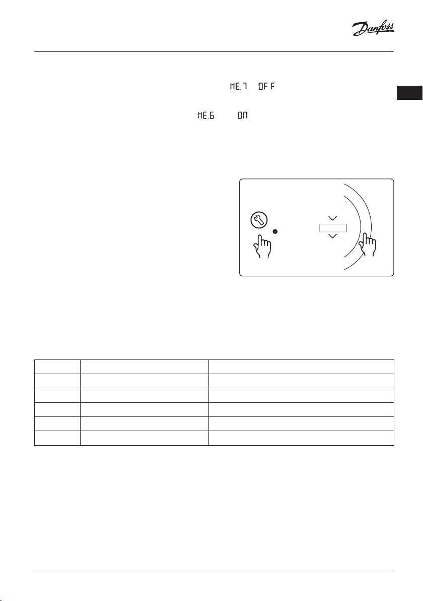
Application test function
Enter the “Test” menu via the installer key.
The Application test (APP test) is specific for each application. The test is split into steps to ensure that all components are installed correctly. Please follow the process.
Test steps
RUN
INSTALL
UNINSTALL
TEST
TEST NET
TEST APP
TEST FL
O
Step 1:1 Go to mixing shunt control valve actuator, and
verify that the valve opens fully (up to 3 minutes opening
time can be expected). After 5 minutes, the mixing shunt
valve actuator will close again.
During the 5 minute test period, the display on the master
controller will also show the measured supply flow temperature in the display.
Parts list
Pos. 1 088U0093-96 1 pc. Danfoss FHM-Cx Mixing shunt
Pos. 2 088U05XX / 088U06XX / 088U07XX 1 set Danfoss Manifold (types FHF or BasicPlus or SSM)
Pos. 3 NC: 088H3110 / NO: 088H3111 xx pcs. thermal actuator, 24 V TWA-A
Pos. 4 087B1165 1 pc. ESM-11 PT-1000 sensor
Pos. 5. NC: 088H3110 / NC: 193B2148 1 pc. thermal actuator, 24 V (types TWA-A or ABN-FBH)
OK
8 | © Danfoss | FEC | 2018.12 VIMDE20F / 088N2100
Page 9
Installation Guide Expansion Module for Danfoss Icon™ Master
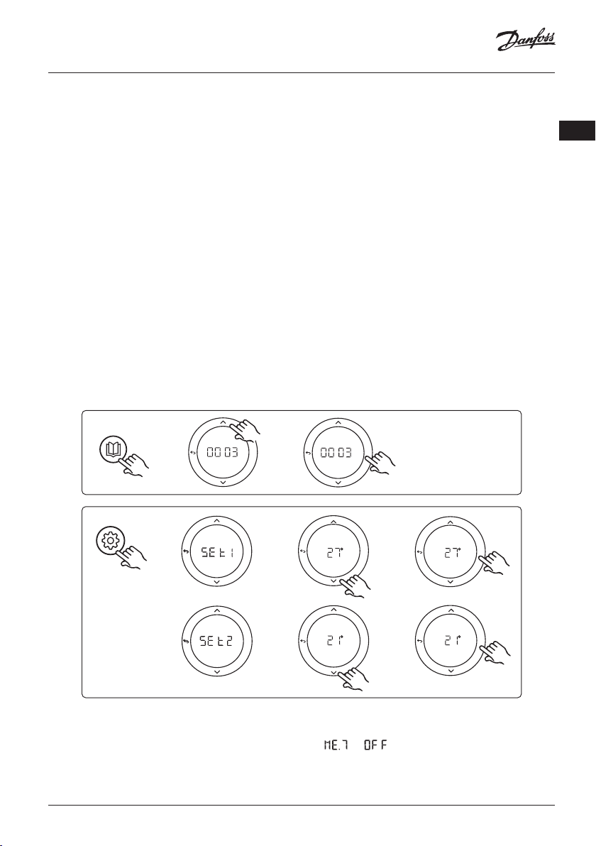
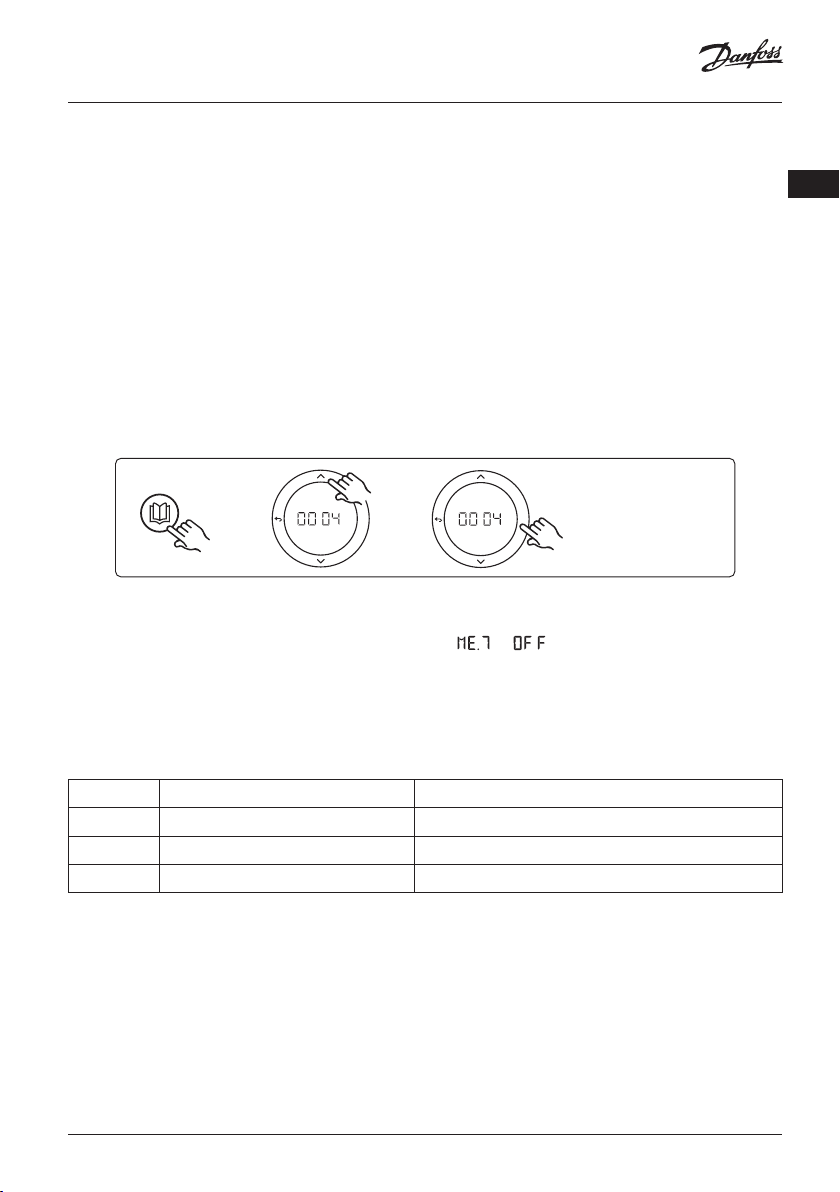
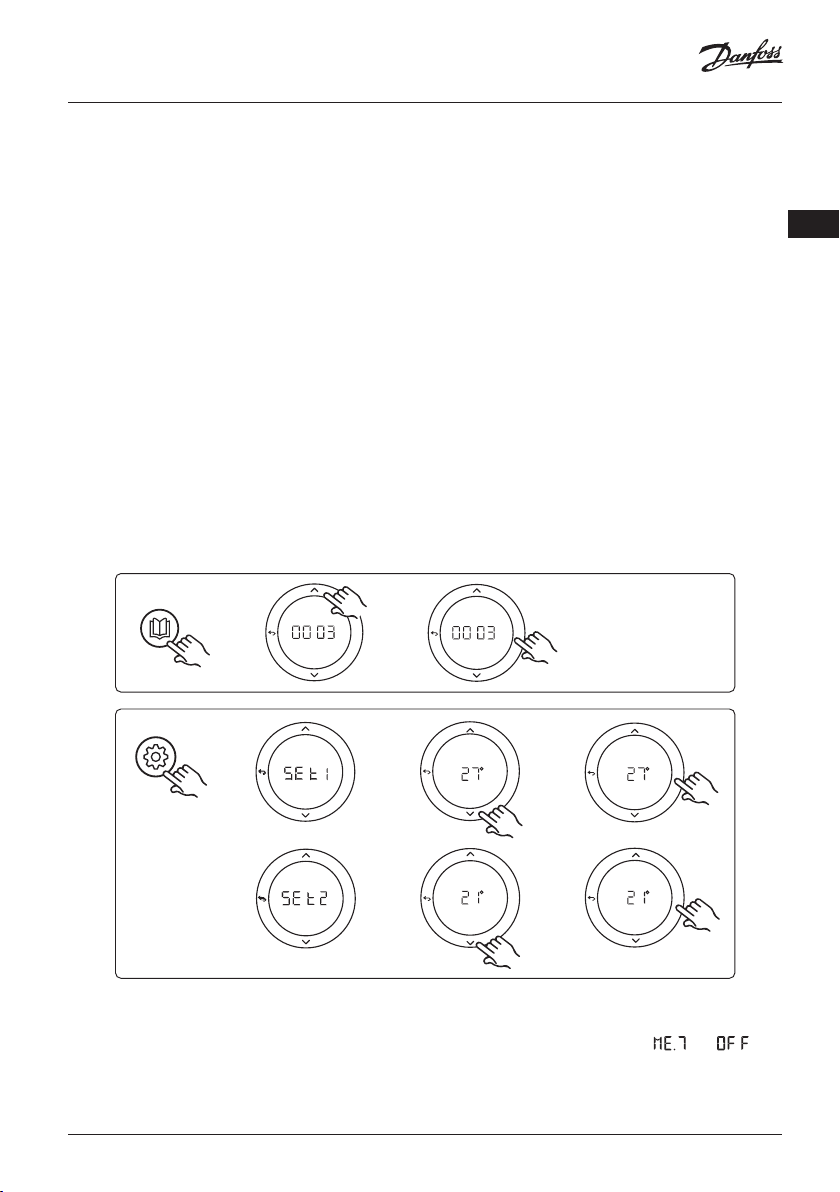
Application 0003: 2-pipe system with automatic changeover for cooling based
on supply temperature.
Optional: Dewpoint sensor (recommended), Global standby, Circulation pump and heat demand
signal.
Application description
Floor heating system with automatic changeover for cooling based on supply temperature input.
The supply temperature is monitered using a PT1000 sensor. Based on the measurement, the system
switches to heating or cooling. If connected, the system will control the circulation pump which will be
turned on when minimum 1 room has a heat or cooling demand.
The heat signal for e.g. a boiler or heat pump is only activated when the system is in heating mode and
minimum 1 room has a heat demand. For cooling applications it is always recommended to have a dew
point sensor installed in the system to prevent moisture damage to floor and installations in cases where
the relative humidty exceeds dew point.
The Global standby is a potential free input that can be used to remotely put the system in Global away
mode e.g. via an external 3rd party GSM module. When global standby input is active, all rooms receive a 15
degree celcius setpoint.
Settings
“SET 1” = Set supply flow temperature for change-over to heating [25-55°C]
“SET 2” = Set supply flow temperature for change-over to cooling [15-25°C]
Note: temperature cannot be set higher than 2°C lower than heating change-over temperature.
GB
APPLICATION
SETTINGS
OK
OK
OK
OK
OK
OK
OK
OK
Settings on thermostat
Excluding rooms from cooling: To exclude a room from cooling - typically in bathrooms where cooling
would be uncomfortable - go to thermostat and set menu to . See Thermostat Installation Guide
for further information.
© Danfoss | FEC | 2018.12 | 9VIMDE20F / 088N2100
Page 10

Installation Guide Expansion Module for Danfoss Icon™ Master
Application test function
Enter the “Test” menu via the installer key.
The Application test (APP test) is specific for each application. The test is split into steps to ensure that all components are installed correctly. Please follow the process.
Test steps
RUN
INSTALL
UNINSTALL
TEST
TEST NET
TEST APP
TEST FL
O
Step 1:1 During the 1 minute test period, the display on
the master controller will show the measured supply flow
temperature in the display.
Parts list
Pos. 1 087B1165 1 pc. ESM-11 PT1000 sensor
Pos. 2 088U05XX / 088U06XX / 088U07XX 1 set Danfoss Manifold (types FHF or BasicPlus or SSM)
Pos. 3 NC: 088H3110 / NO: 088H3111 xx pcs. thermal actuator, 24 V TWA-A
Pos. 4 088U0251 1 pc. dew point sensor, type CF-DS
OK
10 | © Danfoss | FEC | 2018.12 VIMDE20F / 088N2100
Page 11
Installation Guide Expansion Module for Danfoss Icon™ Master
Application 0004: 2 pipe system with heat pump controlled changeover to
cooling.
Optional: Dewpoint sensor (recommended), Circulation pump and heat demand signal.
Application description
Floor heating system with automatic changeover for cooling controlled by heat source e.g. heat pump.
The heat pump provides the cooling signal to the Danfoss Icon™ Master, when the heat pump goes into
cooling mode thus activating cooling mode. If connected, the system will control the circulation pump and
it will be turned on when minimum 1 room has a heat or cooling demand.
The heat signal for e.g. a boiler or heat pump is only activated when the system is in heating mode and
minimum 1 room has a heat demand. For cooling applications it is always recommended to have a dew
point sensor installed in the system to prevent moisture damage to floor and installations in cases where
the relative humidty exceeds dew point.
Settings
No settings necessary.
GB
APPLICATION
OK
OK
Settings on thermostat
Excluding rooms from cooling: To exclude a room from cooling - typically in bathrooms where cooling
would be uncomfortable - go to thermostat and set menu to . See Thermostat Installation Guide
for further information.
Application test function
Not relevant.
Parts list
Pos. 1 NA 1 pc. heat pump
Pos. 2 088U05XX / 088U06XX / 088U07XX 1 set Danfoss Manifold (types FHF or BasicPlus or SSM)
Pos. 3 NC: 088H3110 / NO: 088H3111 xx pcs. thermal actuator, 24 V TWA-A
Pos. 4 088U0251 1 pc. dew point sensor, type CF-DS
© Danfoss | FEC | 2018.12 | 11VIMDE20F / 088N2100
Page 12
Installation Guide Expansion Module for Danfoss Icon™ Master
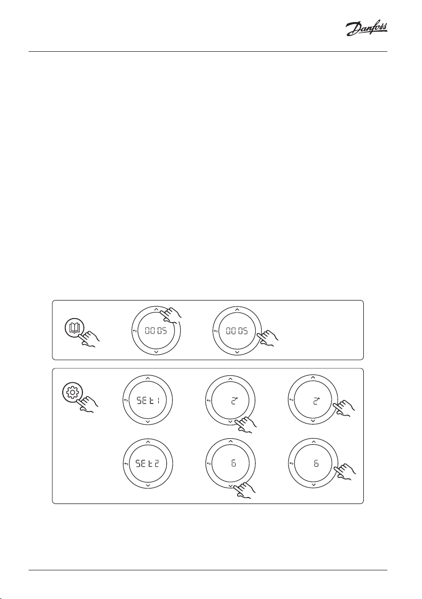
Application 0005: 2 pipe system with hybrid Air/water heat pump with integrated condensing boiler (example: Itho Cool Cube). Change over ordered from
reference room thermostat.
Optional: Dewpoint sensor (recommended) and Global standby.
Application description
Floor heating system with cooling done via e.g. Coolcube used as heating and cooling source.
The Icon™ system controls the heat and cooling demand by activating the corrosponding relay (PWR1
and potential free relay). For cooling applications it is always recommended to have a dew point sensor
installed in the system to prevent moisture damage to floor and installations in cases where the relative
humidty exceeds dew point. Four conditions must be true before cooling in a room is allowed:
• Reference room temperature must exceed the room setpoint + cooling hysterhesis.
• No room has called for heating within neutral time.
• The dew point sensor must not be active / no condensation risk present.
• The room thermostat must be enabled for cooling (default = enabled).
The Global standby is a potential free input that can be used to remotely put the system in Global away
mode e.g. via an external 3rd party GSM module. When global standby input is active, all rooms receive a 15
degree celcius setpoint.
Settings
“SET 1” = Set desired cooling hysterhesis for change-over [+2 to +4K]
“SET 2” = Set neutral time that must pass without active heating or cooling, before change-over can be
activated [3-6 Hrs.]
APPLICATION
SETTINGS
12 | © Danfoss | FEC | 2018.12 VIMDE20F / 088N2100
OK
OK
OK
OK
OK
OK
OK
OK
Page 13

Installation Guide Expansion Module for Danfoss Icon™ Master
Settings on thermostat
Excluding rooms from cooling: To exclude a room from cooling - typically in bathrooms where cooling
would be uncomfortable - go to thermostat and set menu to . See Thermostat Installation Guide
for further information.
Choose reference room thermostat: To assign a thermostat as reference room thermostat, go to the
desired reference room thermostat and in menu set to .
When selected the thermostat will control when the system goes from heating mode to cooling mode
based on the actual temperature in the room.
It is only possible to have one reference thermostat per system and if more than one thermostats are
assigned as reference, the last assigned will overwrite the previous reference room thermostats and cause
these to revert to normal function.
Application test function
Enter the “Test” menu via the installer key.
The Application test (APP test) is specific for each application. The test is split into steps to ensure that all components are installed correctly. Please follow the process.
Test steps
Step 1:3 During the first minute of the test, the heat
source is set to "heating mode" via "PWR1 output". Check
on heat source user interface that heating is active.
Step 2:3 During the second minute of the test, the heat
source is set to "cooling mode" via "Relay output". Check
on heat source user interface that cooling is active
Step 3:3 During the third minute of the test, the heat
source is set to "neutral mode", neither heating nor cooling
is active.
RUN
INSTALL
UNINSTALL
TEST
TEST NET
TEST APP
TEST FL
OK
O
GB
Parts list
Pos. 1 NA 1 pc. e.g. Coolcube
Pos. 2 088U05XX / 088U06XX / 088U07XX 1 set Danfoss Manifold (types FHF or BasicPlus or SSM)
Pos. 3 NC: 088H3110 / NO: 088H3111 xx pcs. thermal actuator, 24 V TWA-A
Pos. 4 088U0251 1 pc. dew point sensor, type CF-DS
Pos. 5. NA
External relay (convert 230 V to potential free relay), not
supplied by Danfoss
© Danfoss | FEC | 2018.12 | 13VIMDE20F / 088N2100
Page 14
Installation Guide Expansion Module for Danfoss Icon™ Master
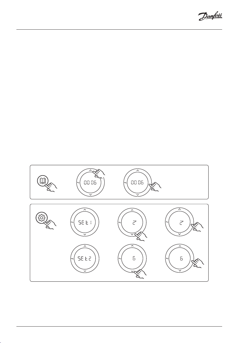
Application 0006: 3-pipe system with cooling control via motorized valve and
common return, change over signal ordered by reference room thermostat.
Optional: Dewpoint sensor (recommended), Global standby and heat demand signal relay.
Application description
3 -pipe Floor heating system with cooling controlled via motorized valve and common return.
The Icon™ system controls the heat and cooling demand by activating the corresponding relay (PWR1
and PWR2). For cooling applications it is always recommended to have a dew point sensor installed in the
system to prevent moisture damage to floor and installations in cases where the relative humidty exceeds
dew point. Four conditions must be true before cooling in a room is allowed:
• Reference room temperature must exceed the room setpoint + cooling hysterhesis.
• No room has called for heating within neutral time.
• The dew point sensor must not be active / no condensation risk present.
• The room thermostat must be enabled for cooling (default = enabled).
The Global standby is a potential free input that can be used to remotely put the system in Global away
mode e.g. via an external 3rd party GSM module. When global standby input is active, all rooms receive a 15
degree celcius setpoint.
Settings
“SET 1” = Set desired cooling hysterhesis for change-over [+2 to +4K]
“SET 2” = Set neutral time that must pass without active heating or cooling, before change-over can be
activated [3-6 Hrs.]
APPLICATION
SETTINGS
14 | © Danfoss | FEC | 2018.12 VIMDE20F / 088N2100
OK
OK
OK
OK
OK
OK
OK
OK
Page 15

Installation Guide Expansion Module for Danfoss Icon™ Master
Settings on thermostat
Excluding rooms from cooling: To exclude a room from cooling - typically in bathrooms where cooling
would be uncomfortable - go to thermostat and set menu to . See Thermostat Installation Guide
for further information.
Choose reference room thermostat: To assign a thermostat as reference room thermostat, go to the
desired reference room thermostat and in menu set to .
When selected the thermostat will control when the system goes from heating mode to cooling mode
based on the actual temperature in the room.
It is only possible to have one reference thermostat per system and if more than one thermostats are
assigned as reference, the last assigned will overwrite the previous reference room thermostats and cause
these to revert to normal function.
Application test function
Enter the “Test” menu via the installer key.
The Application test (APP test) is specific for each application. The test is split into steps to ensure that all components are installed correctly. Please follow the process.
Test steps
Step 1:2 During the first minute of the test, the AMZ 113
valve is set to "heating mode" via "PWR1 output going
ON". Check on valve/actuator that position is correct for
"heating".
Step 2:2 During the second minute of the test, the AMZ
113 valve is set to "cooling mode" via "PWR1 output going
OFF". Check on valve/actuator that position is correct for
"Cooling".
RUN
INSTALL
UNINSTALL
TEST
TEST NET
TEST APP
TEST FL
OK
O
GB
Parts list
Pos. 1 DN15: 082G5511 DN20: 088G5512 1 pc. AMZ 113 (3 -way valve)
Pos. 2 088U05XX / 088U06XX / 088U07XX 1 set Danfoss Manifold (types FHF or BasicPlus or SSM)
Pos. 3 NC: 088H3110 / NO: 088H3111 xx pcs. thermal actuator, 24 V TWA-A
Pos. 4 088U0251 1 pc. dew point sensor, type CF-DS
© Danfoss | FEC | 2018.12 | 15VIMDE20F / 088N2100
Page 16
Installation Guide Expansion Module for Danfoss Icon™ Master
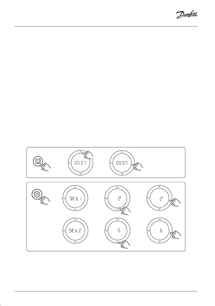
Application 0007: 3-pipe system with cooling control via thermal actuators and
common return controlled by reference room thermostat.
Optional: Dewpoint sensor (recommended), Global standby, pump relay and heat demand signal.
Application description
3 -pipe Floor heating system with cooling controlled via thermal actuators and common return.
The Icon™ system controls the heat and cooling demand by activating the corresponding outputs (M1 and
M2). For cooling applications it is always recommended to have a dew point sensor installed in the system
to prevent moisture damage to floor and installations in cases where the relative humidty exceeds dew
point. Four conditions must be true before cooling in a room is allowed:
• Reference room temperature must exceed the room setpoint + cooling hysterhesis.
• No room has called for heating within neutral time.
• The dew point sensor must not be active / no condensation risk present.
• The room thermostat must be enabled for cooling (default = enabled).
The Global standby is a potential free input that can be used to remotely put the system in Global away
mode e.g. via an external 3rd party GSM module. When global standby input is active, all rooms receive a 15
degree celcius setpoint.
Settings
“SET 1” = Set desired cooling hysterhesis for change-over [+2 to +4K]
“SET 2” = Set neutral time that must pass without active heating or cooling, before change-over can be
activated [3-6 Hrs.]
APPLICATION
SETTINGS
16 | © Danfoss | FEC | 2018.12 VIMDE20F / 088N2100
OK
OK
OK
OK
OK
OK
OK
OK
Page 17

Installation Guide Expansion Module for Danfoss Icon™ Master
Settings on thermostat
Excluding rooms from cooling: To exclude a room from cooling - typically in bathrooms where cooling
would be uncomfortable - go to thermostat and set menu to . See Thermostat Installation Guide
for further information.
Choose reference room thermostat: To assign a thermostat as reference room thermostat, go to the
desired reference room thermostat and in menu set to .
When selected the thermostat will control when the system goes from heating mode to cooling mode
based on the actual temperature in the room.
It is only possible to have one reference thermostat per system and if more than one thermostats are
assigned as reference, the last assigned will overwrite the previous reference room thermostats and cause
these to revert to normal function.
Application test function
Enter the “Test” menu via the installer key.
The Application test (APP test) is specific for each application. The test is split into steps to ensure that all components are installed correctly. Please follow the process.
Test steps
Step 1:3 During the first five minutes, the output 1
is set to "ON" = heating mode/hot flow side (up to 3
minutes opening time can be expected).
Step 2:3 During next five minutes, the output 1 is
set to "OFF", and the outputs 3 & 4 are set to "ON"
= cooling mode/cold flow side (up to 3 minutes
opening time can be expected).
Step 3:3 During last 5 minutes, all outputs 1 and 2
should close.
RUN
INSTALL
UNINSTALL
TEST
TEST NET
TEST APP
TEST FL
OK
O
GB
Parts list
Pos. 1 DN15: 013G3094 DN20: 013G3016 2 pcs. RA-C valve
Pos. 2 088U05XX / 088U06XX / 088U07XX 1 set Danfoss Manifold (types FHF or BasicPlus or SSM)
Pos. 3 NC: 088H3110 / NO: 088H3111 xx pcs. thermal actuator, 24 V TWA-A
Pos. 4 088U0251 1pc. dew point sensor, type CF-DS
Pos. 5a & 5b 088H3110 2 pcs. thermal actuator, 24 V TWA-A
© Danfoss | FEC | 2018.12 | 17VIMDE20F / 088N2100
Page 18

Installation Guide Expansion Module for Danfoss Icon™ Master
Application 0008: 3-pipe system with cooling control via motorized actuators
and common return controlled by reference room thermostat.
Optional: Dewpoint sensor (recommended), Global standby, pump relay and heat demand signal.
Application description
3 -pipe Floor heating system with cooling controlled via motorized actuators and common return.
The Icon™ system controls the heat and cooling demand by activating the corrosponding outputs (PWR1
and potential free relay). For cooling applications it is always recommended to have a dew point sensor
installed in the system to prevent moisture damage to floor and installations in cases where the relative
humidty exceeds dew point. Four conditions must be true before cooling in a room is allowed:
• Reference room temperature must exceed the room setpoint + cooling hysterhesis.
• No room has called for heating within neutral time.
• The dew point sensor must not be active / no condensation risk present.
• The room thermostat must be enabled for cooling (default = enabled)
If no heating or cooling demand is present, the two shut-off valves will close (AMZ 112).
The Global standby is a potential free input that can be used to remotely put the system in Global away
mode e.g. via an external 3rd party GSM module. When global standby input is active, all rooms receive a 15
degree celcius setpoint.
Settings
“SET 1” = Set desired cooling hysterhesis for change-over [+2 to +4K]
“SET 2” = Set neutral time that must pass without active heating or cooling, before change-over can be
activated [3-6 Hrs.]
APPLICATION
SETTINGS
18 | © Danfoss | FEC | 2018.12 VIMDE20F / 088N2100
OK
OK
OK
OK
OK
OK
OK
OK
Page 19

Installation Guide Expansion Module for Danfoss Icon™ Master
Settings on thermostat
Excluding rooms from cooling: To exclude a room from cooling - typically in bathrooms where cooling
would be uncomfortable - go to thermostat and set menu to . See Thermostat Installation Guide
for further information.
Choose reference room thermostat: To assign a thermostat as reference room thermostat, go to the
desired reference room thermostat and in menu set to .
When selected the thermostat will control when the system goes from heating mode to cooling mode
based on the actual temperature in the room.
It is only possible to have one reference thermostat per system and if more than one thermostats are
assigned as reference, the last assigned will overwrite the previous reference room thermostats and cause
these to revert to normal function.
Application test function
Enter the “Test” menu via the installer key.
The Application test (APP test) is specific for each application. The test is split into steps to ensure that all components are installed correctly. Please follow the process.
Test steps
Step 1:3 During the first minute of the test, the AMZ 112
valve of the hot flow side is set to "heating mode" via
"PWR1 output going ON". Check on valve/actuator that
position is correct for "heating".
Step 2:3 During the second minute of the test, the AMZ
112 valve on the cold flow side is set to "cooling mode"
via "PWR1 output going OFF" and "Relay output" going
ON. Check on valve/actuator that position is correct for
"cooling".
Step 3:3 During last minute of the test, botm AMZ 112
valves are closed.
RUN
INSTALL
UNINSTALL
TEST
TEST NET
TEST APP
TEST FL
OK
O
GB
Parts list
Pos. 1a & 1b DN15: 082G5511 DN20: 082G5512 2 pcs. AMZ112
Pos. 2 088U05XX / 088U06XX / 088U07XX 1 set Danfoss Manifold (types FHF or BasicPlus or SSM)
Pos. 3 NC: 088H3110 / NO: 088H3111 xx pcs. thermal actuator, 24 V TWA-A
Pos. 4 088U0251 1 pc. dew point sensor, Type CF-DS
© Danfoss | FEC | 2018.12 | 19VIMDE20F / 088N2100
Page 20
Installation Guide Expansion Module for Danfoss Icon™ Master
Application 0009: 4-pipe system with 6-port valve, automatic change over for
cooling controlled by a reference room thermostat. (Require external 24 VAC PSU).
Optional: Dewpoint sensor (recommended), shut-off function and Global standy.
Application description
Floor heating system with automatic changeover for cooling via 6-way changeover valve controlled by a
reference room thermostat.
The system can be configured with optional shut off function via a Danfoss AMZ-112 2-way ball valve and
Global standby. For cooling applications it is always recommended to have a dew point sensor installed
in the system to prevent moisture damage to floor and installations in cases where the relative humidty
exceeds dew point. Four conditions must be true before cooling in a room is allowed:
• Reference room temperature must exceed the room setpoint + cooling hysterhesis.
• No room has called for heating within neutral time.
• The dew point sensor must not be active / no condensation risk present.
• The room thermostat must be enabled for cooling (default = enabled).
If no heating or cooling demand is present, the shut-off valve will close.
The Global standby is a potential free input that can be used to remotely put the system in Global away
mode e.g. via an external 3rd party GSM module. When global standby input is active, all rooms receive a 15
degree celcius setpoint.
Settings
“SET 1” = Set desired cooling hysterhesis for change-over [+2 to +4K]
“SET 2” = Set neutral time that must pass without active heating or cooling, before change-over can be
activated [3-6 Hrs.]
APPLICATION
SETTINGS
20 | © Danfoss | FEC | 2018.12 VIMDE20F / 088N2100
OK
OK
OK
OK
OK
OK
OK
OK
Page 21
Installation Guide Expansion Module for Danfoss Icon™ Master
Settings on thermostat
Excluding rooms from cooling: To exclude a room from cooling - typically in bathrooms where cooling
would be uncomfortable - go to thermostat and set menu to . See Thermostat Installation Guide
for further information.
Choose reference room thermostat: To assign a thermostat as reference room thermostat, go to the
desired reference room thermostat and in menu set to .
When selected the thermostat will control when the system goes from heating mode to cooling mode
based on the actual temperature in the room.
It is only possible to have one reference thermostat per system and if more than one thermostats are
assigned as reference, the last assigned will overwrite the previous reference room thermostats and cause
these to revert to normal function.
Application test function
Enter the “Test” menu via the installer key.
The Application test (APP test) is specific for each application. The test is split into steps to ensure that all components are installed correctly. Please follow the process.
RUN
INSTALL
UNINSTALL
TEST
Test steps
Step 1:3 During the first two minutes, the AMZ 112 valve
goes to position "Flow" and the ChangeOver6 valve goes
to position "Cooling" for 1 minute.
Step 2:3 The ChangeOver6 valve now goes to position
"Heating" for 1 minute.
Step 3:3 The AMZ 112 valve goes to position "No Flow".
Parts list
Pos. 1 DN 15: 003Z3150 / DN 20: 003Z31511 1 pc. Danfoss ChangeOver6 6-port valve
Pos. 2 003Z3155 1 pc. Danfoss ChangeOver6 actuator
Pos. 3 DN15: 082G5501 / DN20: 082G55021 1 pc. AMZ 112
Pos. 4 088U05XX / 088U06XX / 088U07XX 1 pc. Danfoss manifold (types FHF or BasicPlus or SSM)
Pos. 5 N/A
Pos. 6 088U0251 1 pc. dew point sensor, type CF-DS
Pos. 7 NC: 088H3110 / NO: 088H3111 xx pcs. thermal actuator, 24 V TWA-A
1 pc. external power supply 230 V->24 VAC, not supplied by
Danfoss. Minimum 5 VA output on 24 V side.
TEST NET
TEST APP
TEST FL
OK
O
GB
© Danfoss | FEC | 2018.12 | 21VIMDE20F / 088N2100
Page 22
Installation Guide Expansion Module for Danfoss Icon™ Master
Application 0010: 4-pipe system with 2-way valves on supply pipes and automatic
change over for cooling controlled by a reference room thermostat.
Optional: Dewpoint sensor (recommended), circulation pump, heat demand signal and Global
standby.
Application description
4-pipe system with 2-way valves on supply pipes and automatic change over for cooling controlled by
reference room thermostat.
The system activates cooling mode via 2-way valves with thermal actuators on supply and return side by
activating the corresponding outputs (M1 - M4). Note: In this application outputs 1, 2, 3 & 4 on Danfoss Icon™
Master is used for the application and cannot be assigned to thermostats.
For cooling applications it is always recommended to have a dew point sensor installed in the system to
prevent moisture damage to floor and installations in cases where the relative humidty exceeds dew point.
Four conditions must be true before cooling in a room is allowed:
• Reference room temperature must exceed the room setpoint + cooling hysterhesis.
• No room has called for heating within neutral time.
• The dew point sensor must not be active / no condensation risk present.
• The room thermostat must be enabled for cooling (default = enabled).
The Global standby is a potential free input that can be used to remotely put the system in Global away
mode e.g. via an external 3rd party GSM module. When global standby input is active, all rooms receive a
15 degree celcius setpoint.
Settings
“SET 1” = Set desired cooling hysterhesis for change-over [+2 to +4K]
“SET 2” = Set neutral time that must pass without active heating or cooling, before change-over can be
activated [3-6 Hrs.]
APPLICATION
SETTINGS
22 | © Danfoss | FEC | 2018.12 VIMDE20F / 088N2100
OK
OK
OK
OK
OK
OK
OK
OK
Page 23
Installation Guide Expansion Module for Danfoss Icon™ Master
Settings on thermostat
Excluding rooms from cooling: To exclude a room from cooling - typically in bathrooms where cooling
would be uncomfortable - go to thermostat and set menu to . See Thermostat Installation Guide
for further information.
Choose reference room thermostat: To assign a thermostat as reference room thermostat, go to the
desired reference room thermostat and in menu set to .
When selected the thermostat will control when the system goes from heating mode to cooling mode
based on the actual temperature in the room.
It is only possible to have one reference thermostat per system and if more than one thermostats are
assigned as reference, the last assigned will overwrite the previous reference room thermostats and cause
these to revert to normal function.
Application test function
Enter the “Test” menu via the installer key.
The Application test (APP test) is specific for each application. The test is split into steps to ensure that all components are installed correctly. Please follow the process.
Test steps
Step 1:3 During the first five minutes, the outputs 1&2 are
set to "ON" = heating mode/hot flow side (up to 3 minutes
opening time can be expected).
Step 2:3 During next five minutes, the outputs 1&2 are set
to "OFF", and the outputs 3 & 4 are set to "ON" = cooling
mode/cold flow side (up to 3 minutes opening time can be
expected).
Step 3:3 During last 5 minutes, all outputs 1, 2, 3 and 4
should close.
RUN
INSTALL
UNINSTALL
TEST
TEST NET
TEST APP
TEST FL
OK
O
GB
Parts list
Pos. 1 DN15: 013G3094 DN20: 013G3016 4 pcs. RA-C valve
Pos. 2 088U05XX / 088U06XX / 088U07XX 1 pc. Danfoss manifold (types FHF or BasicPlus or SSM)
Pos. 3 NC: 088H3110 / NO: 088H3111 xx pcs. thermal actuator, 24 V TWA-A
Pos. 4 088U0251 1 pc. dew point sensor, type CF-DS
Pos. 5 NC: 088H3110 2 pcs. thermal actuator, 24 V TWA-A
Pos. 6 NC: 088H3110 2 pcs. thermal actuator, 24 V TWA-A
© Danfoss | FEC | 2018.12 | 23VIMDE20F / 088N2100
Page 24

Installationsanleitung Erweiterungsmodus für Danfoss Icon™ Master
Die Verdrahtung gemäß dem
Schaltdiagramm durchführen und
1
APPLICATION
anschließend das Erweiterungsmodul
für zusätzliche Funktionen in den
Danfoss Icon™ Hauptregler einführen.
2
IN 1
SETTINGS
IN 2 IN 3
3
1. Mit dieser Taste können Sie die
Anwendung auswählen. Drücken
Sie die Anwendungstaste, wählen
Sie mit und Anwendung
1-11 aus und bestätigen Sie mit
„OK“. Wählen Sie die geeignete
Anwendung mithilfe der Anwendungszeichnungen aus.
2. Mit dieser Taste können Sie
anwendungsspezifische Einstellungen einstellen. Die für die gewählte Anwendung verfügbaren
Einstellungen sind in der Anwendungsbeschreibung aufgeführt.
3. LED-Leuchten zeigen den Status
der Eingänge 1 bis 3 an. Vgl. die
Anwendungsbeschreibung für die
jeweilige Anwendung.
4. Anschlussklemmen für den Anschluss verschiedener Verdrahtungen/externer Geräte.
5. Kabel-Zugentlastung.
6. Lösevorrichtung für Verdrahtung/
Kabel.
4
IN 3 IN 2 IN 1
PWR3
PT
24
1000
VDC
5
6
24 | © Danfoss | FEC | 2018.12 VIMDE20F / 088N2100
Page 25
Installationsanleitung Erweiterungsmodus für Danfoss Icon™ Master
Anwendung 0001: Zweirohrsystem, vorgegebene Zulufttemperatur, elektronisch kontrolliert.
Optional: Global Standby.
Anwendungsbeschreibung
Fußbodenheizungssystem mit elektronischer Regelung der Zulufttemperatur. Die Zulufttemperatur ist auf
einen vorgegebenen Wert eingestellt.
Das System nutzt einen PT1000-Fühler, um die Zulufttemperatur zu erkennen und zu regeln, und wird auch
eingesetzt, um sicherzustellen, dass die Temperatur nicht die zulässige Höchsttemperatur übersteigt. Wenn
verbunden, steuert das System die Umwälzpumpe und das Heizbedarfssignal, beispielsweise für einen
Kessel oder eine Wärmepumpe. Die Pumpe und das Heizbedarfssignal sind eingeschaltet, wenn bei mindestens einem Kreislauf Heizbedarf besteht. Ausgang 1 muss für TWA an der Mischergruppe verwendet
werden.
Das Globale Standby ist ein potentialfreier Eingang, mit dem das System per Fernzugriff in den Globalen
Abwesenheitsmodus versetzt werden kann, z. B. über ein externes GSM-Modul eines Drittanbieters. Wenn
der globale Standby-Eingang aktiv ist, erhalten alle Räume einen Sollwert von 15 Grad Celsius.
Einstellungen
„SET 1“ = Gewünschte Vorlauftemperatur [25-70 °C] einstellen
„SET 2“ = Gewünschte Sicherheits-Abschalttemperatur [30-75 °C] einstellen
Hinweis: Die Temperatur muss über der Vorlauftemperatur liegen.
APPLICATION
SETTINGS
OK
OK
OK
OK
OK
DE
OK
OK
OK
© Danfoss | FEC | 2018.12 | 25VIMDE20F / 088N2100
Page 26

Installationsanleitung Erweiterungsmodus für Danfoss Icon™ Master
Anwendungstestfunktion
Rufen Sie über die Installateurstaste das Menü „Test“ auf.
Der Anwendungstest (APP-Test) ist anwendungsspezifisch.
Der Test ist in mehrere Schritte unterteilt, um sicherzustellen, dass alle Komponenten ordnungsgemäß installiert
werden. Befolgen Sie bitte das Verfahren.
RUN
INSTALL
UNINSTALL
TEST
TEST NET
TEST APP
TEST FL
OK
O
Testschritte
Schritt 1:1 Gehen Sie zum Regelventilantrieb der Mischer-
gruppe und überprüfen Sie, ob sich das Ventil vollständig
öffnet (es sind bis zu drei Minuten Öffnungszeit zu erwarten). Nach fünf Minuten schließt sich der Ventilantrieb der
Mischergruppe wieder.
Während der fünfminütigen Testphase zeigt das Display am
Hauptregler auch die gemessene Vorlauftemperatur an.
Teileliste
Pos. 1 088U0093-96 1 Stk. Danfoss FHM-Cx Mischergruppe
Pos. 2 088U05XX/088U06XX/088U07XX 1 Satz Danfoss Verteiler (Typen FHF oder BasicPlus oder SSM)
Pos. 3 NC: 088H3110/NO: 088H3111 xx Stk. Thermischer Stellantrieb, 24 V TWA-A
Pos. 4 087B1165 1 Stk. ESM-11 PT-1000 Fühler
Pos. 5. NC: 088H3110/NC: 193B2148 1 Stk. Thermischer Stellantrieb, 24 V (Typen TWA-A oder ABN-FBH)
26 | © Danfoss | FEC | 2018.12 VIMDE20F / 088N2100
Page 27
Installationsanleitung Erweiterungsmodus für Danfoss Icon™ Master
Anwendung 0002: Zweirohrsystem mit bedarfsbasierter Regelung der
Zulufttemperatur.
Optional: Globales Standby.
Anwendungsbeschreibung
Fußbodenheizungssystem mit elektronischer Regelung der Zulufttemperatur.
Die bedarfsbasierte Zulufttemperatur wird je nach dem Heizbedarf aus den Räumen geregelt. Das System
nutzt einen PT1000-Fühler, um die Zulufttemperatur zu erkennen, und wird auch eingesetzt, um mithilfe
eines Sicherheits-Tmax sicherzustellen, dass die Temperatur nicht die zulässige Höchsttemperatur übersteigt. Wenn verbunden, steuert das System die Umwälzpumpe und das Heizbedarfssignal, beispielsweise
für einen Kessel oder eine Wärmepumpe. Die Pumpe und das Heizbedarfssignal sind eingeschaltet, wenn
bei mindestens einem Kreislauf Heizbedarf besteht. Ausgang 1 muss für TWA an der Mischergruppe
verwendet werden.
Das Globale Standby ist ein potentialfreier Eingang, mit dem das System per Fernzugriff in den Globalen
Abwesenheitsmodus versetzt werden kann, z. B. über ein externes GSM-Modul eines Drittanbieters. Wenn
der globale Standby-Eingang aktiv ist, erhalten alle Räume einen Sollwert von 15 Grad Celsius.
Einstellungen
“SET 1” = Set desired min. supply flow temperature [25-65°C]
„SET 1“ = Gewünschte minimale Vorlauftemperatur [25-65 °C] einstellen
„SET 2“ = Gewünschte maximale Vorlauftemperatur [30-70 °C] einstellen
Hinweis: Die Temperatur muss mindestens 5 °C höher als die minimale Vorlauftemperatur eingestellt werden.
„SET 3“ = Gewünschte Sicherheits-Abschalttemperatur [30-75 °C] einstellen
Hinweis: Die Temperatur muss über der Vorlauftemperatur liegen.
APPLICATION
SETTINGSSETTINGS
OK
OKOK
OK
OKOK
OKOK
DE
OKOK
OKOK
OKOK
OKOK
OKOK
OKOK
© Danfoss | FEC | 2018.12 | 27VIMDE20F / 088N2100
Page 28

Installationsanleitung Erweiterungsmodus für Danfoss Icon™ Master
Anwendungstestfunktion
Rufen Sie über die Installateurstaste das Menü „Test“ auf.
Der Anwendungstest (APP-Test) ist anwendungsspezifisch.
Der Test ist in mehrere Schritte unterteilt, um sicherzustellen, dass alle Komponenten ordnungsgemäß installiert
werden. Befolgen Sie bitte das Verfahren.
Testschritte
Schritt 1:1 Gehen Sie zum Regelventilantrieb der Mischer-
gruppe und überprüfen Sie, ob sich das Ventil vollständig
öffnet (es sind bis zu drei Minuten Öffnungszeit zu erwarten). Nach fünf Minuten schließt sich der Ventilantrieb der
Mischergruppe wieder.
Während der fünfminütigen Testphase zeigt das Display am
Hauptregler auch die gemessene Vorlauftemperatur an.
Teileliste
Pos. 1
Pos. 2
Pos. 3
Pos. 4
Pos. 5.
088U0093-96 1 Stk. Danfoss FHM-Cx Mischergruppe
088U05XX/088U06XX/088U07XX 1 Satz Danfoss Verteiler (Typen FHF oder BasicPlus oder SSM)
NC: 088H3110/NO: 088H3111 xx Stk. Thermischer Stellantrieb, 24 V TWA-A
087B1165 1 Stk. ESM-11 PT-1000 Fühler
NC: 088H3110/NC: 193B2148 1 Stk. Thermischer Stellantrieb, 24 V (Typen TWA-A oder ABN-FBH)
RUN
INSTALL
UNINSTALL
TEST
TEST NET
TEST APP
TEST FL
OK
O
28 | © Danfoss | FEC | 2018.12 VIMDE20F / 088N2100
Page 29
Installationsanleitung Erweiterungsmodus für Danfoss Icon™ Master
Anwendung 0003: Zweirohrsystem mit automatischer Umschaltung zur Kühlung
auf der Grundlage der Zulufttemperatur.
Optional: Taupunktfühler (empfohlen), Globales Standby, Umwälzpumpe und Heizbedarfssignal.
Anwendungsbeschreibung
Fußbodenheizungssystem mit automatischer Umschaltung zur Kühlung auf der Grundlage des Zulufttemperatureingangs.
Die Zulufttemperatur wird mittels eines PT1000-Fühlers überwacht. Je nach Messung schaltet das System
von Heizung auf Kühlung um. Wenn verbunden, steuert das System die Umwälzpumpe, die eingeschaltet
wird, wenn mindestens ein Raum Heiz- oder Kühlbedarf hat.
Das Heizsignal für beispielsweise einen Kessel oder eine Wärmepumpe wird nur aktiviert, wenn sich das
System im Heizmodus befindet und mindestens ein Raum Heizbedarf hat. Für Kühlanwendungen empfiehlt
es sich immer, im System einen Taupunktfühler installiert zu haben, um Feuchtigkeitsschäden an Boden
und Installationen zu vermeiden, wenn die relative Luftfeuchte den Taupunkt übersteigt.
Das Globale Standby ist ein potentialfreier Eingang, mit dem das System per Fernzugriff in den Globalen
Abwesenheitsmodus versetzt werden kann, z. B. über ein externes GSM-Modul eines Drittanbieters. Wenn
der globale Standby-Eingang aktiv ist, erhalten alle Räume einen Sollwert von 15 Grad Celsius.
Einstellungen
„SET 1“ = Vorlauftemperatur für die Umschaltung zum Heizen [25-55 °C] einstellen
„SET 2“ = Vorlauftemperatur für die Umschaltung zum Kühlen [15-25 °C] einstellen
Hinweis: Die Temperatur kann nicht höher als 2 °C unter der Umschalttemperatur zum Heizen eingestellt werden.
APPLICATION
SETTINGS
OK
OK
OK
OK
OK
DE
OK
OK
OK
Einstellungen des Thermostats
Räume von der Kühlung ausschließen: Um einen Raum von der Kühlung auszuschließen, etwa ein Bade-
zimmer, in dem eine Kühlung unangenehm wäre, den Thermostat aufsuchen und Menü auf
einstellen. Weitere Informationen sind in der Installationsanleitung des Thermostats enthalten.
© Danfoss | FEC | 2018.12 | 29VIMDE20F / 088N2100
Page 30

Installationsanleitung Erweiterungsmodus für Danfoss Icon™ Master
Anwendungstestfunktion
Rufen Sie über die Installateurstaste das Menü „Test“ auf.
Der Anwendungstest (APP-Test) ist anwendungsspezifisch.
Der Test ist in mehrere Schritte unterteilt, um sicherzustellen, dass alle Komponenten ordnungsgemäß installiert
werden. Befolgen Sie bitte das Verfahren.
Testschritte
Schritt 1:1 Während der einminütigen Testphase zeigt das
Display am Hauptregler die gemessene Vorlauftemperatur
an.
Teileliste
Pos. 1
Pos. 2
Pos. 3
Pos. 4
087B1165 1 Stk. ESM-11 PT1000 Fühler
088U05XX/088U06XX/088U07XX 1 Satz Danfoss Verteiler (Typen FHF oder BasicPlus oder SSM)
NC: 088H3110/NO: 088H3111 xx Stk. Thermischer Stellantrieb, 24 V TWA-A
088U0251 1 Stk. Taupunktfühler, Typ CF-DS
RUN
INSTALL
UNINSTALL
TEST
TEST NET
TEST APP
TEST FL
OK
O
30 | © Danfoss | FEC | 2018.12 VIMDE20F / 088N2100
Page 31

Installationsanleitung Erweiterungsmodus für Danfoss Icon™ Master
Anwendung 0004: Zweirohrsystem mit wärmepumpengeregelter Umschaltung
zur Kühlung.
Optional: Taupunktfühler (empfohlen), Umwälzpumpe und Heizbedarfssignal.
Anwendungsbeschreibung
Fußbodenheizungssystem mit automatischer Umschaltung zur Kühlung, die durch eine Wärmequelle wie z.
B. eine Wärmepumpe gesteuert wird.
Wenn die Wärmepumpe in den Kühlmodus umschaltet, gibt sie ein Kühlsignal an den Danfoss Icon™
Master ab und aktiviert so den Kühlmodus. Wenn verbunden, steuert das System die Umwälzpumpe, die
eingeschaltet wird, wenn mindestens ein Raum Heiz- oder Kühlbedarf hat.
Das Heizsignal für beispielsweise einen Kessel oder eine Wärmepumpe wird nur aktiviert, wenn sich das
System im Heizmodus befindet und mindestens ein Raum Heizbedarf hat. Für Kühlanwendungen empfiehlt
es sich immer, im System einen Taupunktfühler installiert zu haben, um Feuchtigkeitsschäden an Boden
und Installationen zu vermeiden, wenn die relative Luftfeuchte den Taupunkt übersteigt.
Einstellungen
Keine Einstellungen erforderlich.
APPLICATION
OK
OK
Einstellungen des Thermostats
Räume von der Kühlung ausschließen: Um einen Raum von der Kühlung auszuschließen, etwa ein Ba-
dezimmer, in dem eine Kühlung unangenehm wäre, den Thermostat aufsuchen und Menü auf
einstellen. Weitere Informationen sind in der Installationsanleitung des Thermostats enthalten.
Anwendungstestfunktion
Nicht relevant.
Teileliste
Pos. 1
Pos. 2
Pos. 3
Pos. 4
NA 1 Stk. Wärmepumpe
088U05XX/088U06XX/088U07XX 1 Satz Danfoss Verteiler (Typen FHF oder BasicPlus oder SSM)
NC: 088H3110/NO: 088H3111 xx Stk. Thermischer Stellantrieb, 24 V TWA-A
088U0251 1 Stk. Taupunktfühler, Typ CF-DS
DE
© Danfoss | FEC | 2018.12 | 31VIMDE20F / 088N2100
Page 32

Installationsanleitung Erweiterungsmodus für Danfoss Icon™ Master
Anwendung 0005: Zweirohrsystem mit hybrider Luft-Wasser-Wärmepumpe mit
integriertem Brennwertkessel (Beispiel: Itho Cool Cube). Umschaltung vom
Referenzraumthermostat angefordert.
Optional: Taupunktfühler (empfohlen) und Globales Standby.
Anwendungsbeschreibung
Fußbodenheizungssystem mit Kühlung über z. B. Coolcube als Wärme- und Kühlquelle.
Das Icon™ -System steuert den Heiz- und Kühlbedarf durch Aktivierung des entsprechenden Relais (PWR1
und potentialfreies Relais). Für Kühlanwendungen empfiehlt es sich immer, im System einen Taupunktfühler installiert zu haben, um Feuchtigkeitsschäden an Boden und Installationen zu vermeiden, wenn die
relative Luftfeuchte den Taupunkt übersteigt. Bevor die Kühlung in einem Raum zulässig ist, müssen vier
Bedingungen erfüllt sein:
• Die Referenzraumtemperatur muss den Raumsollwert und die Kühlhysterese überschreiten.
• Kein Raum hat innerhalb der neutralen Zeit Heizung angefordert.
• Der Taupunktfühler darf nicht aktiv sein/es darf kein Kondensationsrisiko vorliegen.
• Die Kühlung muss am Raumthermostat aktiviert sein (voreingestellt = aktiviert).
Das Globale Standby ist ein potentialfreier Eingang, mit dem das System per Fernzugriff in den Globalen
Abwesenheitsmodus versetzt werden kann, z. B. über ein externes GSM-Modul eines Drittanbieters. Wenn
der globale Standby-Eingang aktiv ist, erhalten alle Räume einen Sollwert von 15 Grad Celsius.
Einstellungen
„SET 1“ = Gewünschte Kühlhysterese für die Umschaltung [+2 bis +4 K] einstellen
„SET 2“ = Neutrale Zeit einstellen, die ohne aktive Heizung bzw. Kühlung vergehen muss, bevor die Um-
schaltung aktiviert werden kann [3-6 Std.]
APPLICATION
SETTINGS
32 | © Danfoss | FEC | 2018.12 VIMDE20F / 088N2100
OK
OK
OK
OK
OK
OK
OK
OK
Page 33

Installationsanleitung Erweiterungsmodus für Danfoss Icon™ Master
Einstellungen des Thermostats
Räume von der Kühlung ausschließen: Um einen Raum von der Kühlung auszuschließen, etwa ein Bade-
zimmer, in dem eine Kühlung unangenehm wäre, den Thermostat aufsuchen und Menü auf
einstellen. Weitere Informationen sind in der Installationsanleitung des Thermostats enthalten.
Referenzraumthermostat wählen: Um einen Thermostat als Referenzraumthermostat zu bestimmen, den
gewünschten Referenzraumthermostat aufsuchen und Menü auf einstellen.
Nachdem der Thermostat ausgewählt wurde, steuert dieser anhand der tatsächlichen Temperatur im Raum,
wann das System vom Heizmodus in den Kühlmodus umschaltet.
Es kann nur einen Referenzraumthermostat je System geben. Werden mehr als ein Thermostat als Referenz
bestimmt, überschreibt der zuletzt bestimmte Thermostat alle vorher bestimmten Referenzraumthermostate,
sodass diese zur Normalfunktion zurückkehren.
Anwendungstestfunktion
Rufen Sie über die Installateurstaste das Menü „Test“ auf.
Der Anwendungstest (APP-Test) ist anwendungsspezifisch.
Der Test ist in mehrere Schritte unterteilt, um sicherzustellen, dass alle Komponenten ordnungsgemäß installiert
werden. Befolgen Sie bitte das Verfahren.
RUN
INSTALL
UNINSTALL
TEST
TEST NET
TEST APP
TEST FL
OK
O
Testschritte
Schritt 1:3 In der ersten Minute des Tests wird die Wär-
mequelle über den „Ausgang PWR1“ in den „Heizmodus“
versetzt. Überprüfen Sie an der Benutzeroberfläche der
Wärmequelle, ob die Heizung aktiv ist.
Schritt 2:3 In der zweiten Minute des Tests wird die Wärmequelle über einen „Relaisausgang“ in den „Kühlmodus“
versetzt. Überprüfen Sie an der Benutzeroberfläche der
Wärmequelle, ob die Kühlung aktiv ist.
Schritt 3:3 In der dritten Minute des Tests wird die Wärmequelle in den „neutralen Modus“ versetzt und weder
Heizung noch Kühlung sind aktiv.
DE
Teileliste
Pos. 1 NA 1 Stk., z. B. Coolcube
Pos. 2 088U05XX/088U06XX/088U07XX 1 Satz Danfoss Verteiler (Typen FHF oder BasicPlus oder SSM)
Pos. 3 NC: 088H3110/NO: 088H3111 xx Stk. Thermischer Stellantrieb, 24 V TWA-A
Pos. 4 088U0251 1 Stk. Taupunktfühler, Typ CF-DS
Pos. 5 NA
Externes Relais (Umwandlung von 230 V in potentialfreies Relais)
Wird von Danfoss nicht zur Verfügung gestellt
© Danfoss | FEC | 2018.12 | 33VIMDE20F / 088N2100
Page 34

Installationsanleitung Erweiterungsmodus für Danfoss Icon™ Master
Anwendung 0006: Dreirohrsystem mit Kühlungssteuerung über motorisiertes
Ventil und gemeinsame Rückführung, Umschaltsignal von Referenzraumthermostat abgegeben.
Optional: Taupunktfühler (empfohlen), Globales Standby, und Heizbedarfssignalrelais.
Anwendungsbeschreibung
Dreirohr-Fußbodenheizungssystem mit Kühlungssteuerung über motorisiertes Ventil und gemeinsame
Rückführung.
Das Icon™ -System steuert den Heiz- und Kühlbedarf durch Aktivierung des entsprechenden Relais (PWR1
und PWR2). Für Kühlanwendungen empfiehlt es sich immer, im System einen Taupunktfühler installiert zu
haben, um Feuchtigkeitsschäden an Boden und Installationen zu vermeiden, wenn die relative Luftfeuchte
den Taupunkt übersteigt. Bevor die Kühlung in einem Raum zulässig ist, müssen vier Bedingungen erfüllt
sein:
• Die Referenzraumtemperatur muss den Raumsollwert und die Kühlhysterese überschreiten.
• Kein Raum hat innerhalb der neutralen Zeit Heizung angefordert.
• Der Taupunktfühler darf nicht aktiv sein/es darf kein Kondensationsrisiko vorliegen.
• Die Kühlung muss am Raumthermostat aktiviert sein (voreingestellt = aktiviert).
Das Globale Standby ist ein potentialfreier Eingang, mit dem das System per Fernzugriff in den Globalen
Abwesenheitsmodus versetzt werden kann, z. B. über ein externes GSM-Modul eines Drittanbieters. Wenn
der globale Standby-Eingang aktiv ist, erhalten alle Räume einen Sollwert von 15 Grad Celsius.
Einstellungen
„SET 1“ = Gewünschte Kühlhysterese für die Umschaltung [+2 bis +4 K] einstellen
„SET 2“ = Neutrale Zeit einstellen, die ohne aktive Heizung bzw. Kühlung vergehen muss, bevor die Um-
schaltung aktiviert werden kann [3-6 Std.]
APPLICATION
SETTINGS
34 | © Danfoss | FEC | 2018.12 VIMDE20F / 088N2100
OK
OK
OK
OK
OK
OK
OK
OK
Page 35

Installationsanleitung Erweiterungsmodus für Danfoss Icon™ Master
Einstellungen des Thermostats
Räume von der Kühlung ausschließen: Um einen Raum von der Kühlung auszuschließen, etwa ein Bade-
zimmer, in dem eine Kühlung unangenehm wäre, den Thermostat aufsuchen und Menü auf
einstellen. Weitere Informationen sind in der Installationsanleitung des Thermostats enthalten.
Referenzraumthermostat wählen: Um einen Thermostat als Referenzraumthermostat zu bestimmen, den
gewünschten Referenzraumthermostat aufsuchen und Menü auf einstellen.
Nachdem der Thermostat ausgewählt wurde, steuert dieser anhand der tatsächlichen Temperatur im
Raum, wann das System vom Heizmodus in den Kühlmodus umschaltet.
Es kann nur einen Referenzraumthermostat je System geben. Werden mehr als ein Thermostat als Referenz
bestimmt, überschreibt der zuletzt bestimmte Thermostat alle vorher bestimmten Referenzraumthermostate,
sodass diese zur Normalfunktion zurückkehren.
Anwendungstestfunktion
Rufen Sie über die Installateurstaste das Menü „Test“ auf.
Der Anwendungstest (APP-Test) ist anwendungsspezifisch.
Der Test ist in mehrere Schritte unterteilt, um sicherzustellen, dass alle Komponenten ordnungsgemäß installiert
werden. Befolgen Sie bitte das Verfahren.
RUN
INSTALL
UNINSTALL
TEST
TEST NET
TEST APP
TEST FL
OK
O
Testschritte
Schritt 1:2 In der ersten Minute des Tests wird das Ventil
AMZ 113 über die „Aktivierung des Ausgangs PWR1“ in
den „Heizmodus“ versetzt. Überprüfen Sie am Ventil/Stellantrieb, dass die Position für die „Heizung“ korrekt ist.
Schritt 2:2 In der zweiten Minute des Tests wird das Ventil
AMZ 113 über die „Deaktivierung des Ausgangs PWR1“ in
den „Kühlmodus“ versetzt. Überprüfen Sie am Ventil/Stellantrieb, dass die Position für die „Kühlung“ korrekt ist.
DE
Teileliste
Pos. 1
Pos. 2
Pos. 3
Pos. 4
DN 15: 082G5511 DN20: 088G5512 1 Stk. AMZ 113 (3-Wege-Ventil)
088U05XX/088U06XX/088U07XX 1 Satz Danfoss Verteiler (Typen FHF oder BasicPlus oder SSM)
NC: 088H3110/NO: 088H3111 xx Stk. Thermischer Stellantrieb, 24 V TWA-A
088U0251 1 Stk. Taupunktfühler, Typ CF-DS
© Danfoss | FEC | 2018.12 | 35VIMDE20F / 088N2100
Page 36

Installationsanleitung Erweiterungsmodus für Danfoss Icon™ Master
Anwendung 0007: Dreirohrsystem mit Kühlungssteuerung über thermische
Stellantriebe und gemeinsame Rückführung, gesteuert durch das Referenzraumthermostat.
Optional: Taupunktfühler (empfohlen), Globales Standby, Pumpenrelais und Heizbedarfssignal.
Anwendungsbeschreibung
Dreirohr-Fußbodenheizungssystem mit Kühlungssteuerung über thermische Stellantriebe und gemeinsame Rückführung.
Das Icon™ -System steuert den Heiz- und Kühlbedarf durch Aktivierung des entsprechenden Relais (M1 und
M2). Für Kühlanwendungen empfiehlt es sich immer, im System einen Taupunktfühler installiert zu haben,
um Feuchtigkeitsschäden an Boden und Installationen zu vermeiden, wenn die relative Luftfeuchte den
Taupunkt übersteigt. Bevor die Kühlung in einem Raum zulässig ist, müssen vier Bedingungen erfüllt sein:
• Die Referenzraumtemperatur muss den Raumsollwert und die Kühlhysterese überschreiten.
• Kein Raum hat innerhalb der neutralen Zeit Heizung angefordert.
• Der Taupunktfühler darf nicht aktiv sein/es darf kein Kondensationsrisiko vorliegen.
• Die Kühlung muss am Raumthermostat aktiviert sein (voreingestellt = aktiviert).
Das Globale Standby ist ein potentialfreier Eingang, mit dem das System per Fernzugriff in den Globalen
Abwesenheitsmodus versetzt werden kann, z. B. über ein externes GSM-Modul eines Drittanbieters. Wenn
der globale Standby-Eingang aktiv ist, erhalten alle Räume einen Sollwert von 15 Grad Celsius.
Einstellungen
„SET 1“ = Gewünschte Kühlhysterese für die Umschaltung [+2 bis +4 K] einstellen
„SET 2“ = Neutrale Zeit einstellen, die ohne aktive Heizung bzw. Kühlung vergehen muss, bevor die Um-
schaltung aktiviert werden kann [3-6 Std.]
APPLICATION
SETTINGS
36 | © Danfoss | FEC | 2018.12 VIMDE20F / 088N2100
OK
OK
OK
OK
OK
OK
OK
OK
Page 37

Installationsanleitung Erweiterungsmodus für Danfoss Icon™ Master
Einstellungen des Thermostats
Räume von der Kühlung ausschließen: Um einen Raum von der Kühlung auszuschließen, etwa ein Bade-
zimmer, in dem eine Kühlung unangenehm wäre, den Thermostat aufsuchen und Menü auf
einstellen. Weitere Informationen sind in der Installationsanleitung des Thermostats enthalten.
Referenzraumthermostat wählen: Um einen Thermostat als Referenzraumthermostat zu bestimmen, den
gewünschten Referenzraumthermostat aufsuchen und Menü auf einstellen.
Nachdem der Thermostat ausgewählt wurde, steuert dieser anhand der tatsächlichen Temperatur im Raum,
wann das System vom Heizmodus in den Kühlmodus umschaltet.
Es kann nur einen Referenzraumthermostat je System geben. Werden mehr als ein Thermostat als Referenz
bestimmt, überschreibt der zuletzt bestimmte Thermostat alle vorher bestimmten Referenzraumthermostate,
sodass diese zur Normalfunktion zurückkehren.
Anwendungstestfunktion
Rufen Sie über die Installateurstaste das Menü „Test“ auf.
Der Anwendungstest (APP-Test) ist anwendungsspezifisch.
Der Test ist in mehrere Schritte unterteilt, um sicherzustellen, dass alle Komponenten ordnungsgemäß installiert
werden. Befolgen Sie bitte das Verfahren.
RUN
INSTALL
UNINSTALL
TEST
TEST NET
TEST APP
TEST FL
OK
O
Testschritte
Schritt 1:3 In den ersten fünf Minuten stehen
die Aus gänge 1 auf „ON“ = Heizmodus/Seite mit
heißem Durchfluss (es sind bis zu drei Minuten
Öffnungszeit zu erwarten).
Schritt 2:3 In den nächsten fünf Minuten stehen die
Ausgänge 1 auf „OFF“ und die Ausgänge 2 auf „ON“
= Kühlmodus/Seite mit kaltem Durchfluss (es sind
bis zu drei Minuten Öffnungszeit zu erwarten).
Schritt 3:3 In den letzten fünf Minuten sollten sich
alle Ausgänge 1 und 2 schließen.
DE
Teileliste
Pos. 1 DN 15: 013G3094 DN20: 013G3016 2 Stk. RA-C-Ventil
Pos. 2 088U05XX/088U06XX/088U07XX 1 Satz Danfoss Verteiler (Typen FHF oder BasicPlus oder SSM)
Pos. 3 NC: 088H3110/NO: 088H3111 xx Stk. Thermischer Stellantrieb, 24 V TWA-A
Pos. 4 088U0251 1 Stk. Taupunktfühler, Typ CF-DS
Pos. 5a & 5b 088H3110 2 Stk. Thermischer Stellantrieb, 24 V TWA-A
© Danfoss | FEC | 2018.12 | 37VIMDE20F / 088N2100
Page 38

Installationsanleitung Erweiterungsmodus für Danfoss Icon™ Master
Anwendung 0008: Dreirohrsystem mit Kühlungssteuerung über motorisierte
Stellantriebe und gemeinsame Rückführung, gesteuert durch das Referenzraumthermostat.
Optional: Taupunktfühler (empfohlen), Globales Standby, Pumpenrelais und Heizbedarfssignal.
Anwendungsbeschreibung
Dreirohr-Fußbodenheizungssystem mit Kühlungssteuerung über motorisierte Stellantriebe und gemeinsame Rückführung.
Das Icon™ -System steuert den Heiz- und Kühlbedarf durch Aktivierung der entsprechenden Ausgänge (PWR1 und potentialfreies Relais). Für Kühlanwendungen empfiehlt es sich immer, im System einen
Taupunktfühler installiert zu haben, um Feuchtigkeitsschäden an Boden und Installationen zu vermeiden,
wenn die relative Luftfeuchte den Taupunkt übersteigt. Bevor die Kühlung in einem Raum zulässig ist,
müssen vier Bedingungen erfüllt sein:
• Die Referenzraumtemperatur muss den Raumsollwert und die Kühlhysterese überschreiten.
• Kein Raum hat innerhalb der neutralen Zeit Heizung angefordert.
• Der Taupunktfühler darf nicht aktiv sein/es darf kein Kondensationsrisiko vorliegen.
• Die Kühlung muss am Raumthermostat aktiviert sein (voreingestellt = aktiviert)
Wenn kein Heiz- oder Kühlbedarf vorliegt, schließen sich die beiden Absperrventile (AMZ 112).
Das Globale Standby ist ein potentialfreier Eingang, mit dem das System per Fernzugriff in den Globalen
Abwesenheitsmodus versetzt werden kann, z. B. über ein externes GSM-Modul eines Drittanbieters. Wenn
der globale Standby-Eingang aktiv ist, erhalten alle Räume einen Sollwert von 15 Grad Celsius.
Einstellungen
„SET 1“ = Gewünschte Kühlhysterese für die Umschaltung [+2 bis +4 K] einstellen
„SET 2“ = Neutrale Zeit einstellen, die ohne aktive Heizung bzw. Kühlung vergehen muss, bevor die Um-
schaltung aktiviert werden kann [3-6 Std.]
APPLICATION
SETTINGS
38 | © Danfoss | FEC | 2018.12 VIMDE20F / 088N2100
OK
OK
OK
OK
OK
OK
OK
OK
Page 39

Installationsanleitung Erweiterungsmodus für Danfoss Icon™ Master
Einstellungen des Thermostats
Räume von der Kühlung ausschließen: Um einen Raum von der Kühlung auszuschließen, etwa ein Bade-
zimmer, in dem eine Kühlung unangenehm wäre, den Thermostat aufsuchen und Menü auf
einstellen. Weitere Informationen sind in der Installationsanleitung des Thermostats enthalten.
Referenzraumthermostat wählen: Um einen Thermostat als Referenzraumthermostat zu bestimmen, den
gewünschten Referenzraumthermostat aufsuchen und Menü auf einstellen.
Nachdem der Thermostat ausgewählt wurde, steuert dieser anhand der tatsächlichen Temperatur im Raum,
wann das System vom Heizmodus in den Kühlmodus umschaltet.
Es kann nur einen Referenzraumthermostat je System geben. Werden mehr als ein Thermostat als Referenz
bestimmt, überschreibt der zuletzt bestimmte Thermostat alle vorher bestimmten Referenzraumthermostate,
sodass diese zur Normalfunktion zurückkehren.
Anwendungstestfunktion
Rufen Sie über die Installateurstaste das Menü „Test“ auf.
Der Anwendungstest (APP-Test) ist anwendungsspezifisch.
Der Test ist in mehrere Schritte unterteilt, um sicherzustellen, dass alle Komponenten ordnungsgemäß installiert
werden. Befolgen Sie bitte das Verfahren.
RUN
INSTALL
UNINSTALL
TEST
TEST NET
TEST APP
TEST FL
OK
O
Testschritte
Schritt 1:3 In der ersten Minute des Tests wird das Ventil
AMZ 112 der Seite mit dem heißen Durchfluss über die
„Aktivierung des Ausgangs PWR1“ in den „Heizmodus“
versetzt. Überprüfen Sie am Ventil/Stellantrieb, dass die
Position für die „Heizung“ korrekt ist.
Schritt 2:3 In der zweiten Minute des Tests wird das Ventil
AMZ 112 der Seite mit dem kalten Durchfluss über die
„Deaktivierung des Ausgangs PWR1“ und die Aktivierung
des „Relaisausgangs“ in den „Kühlmodus“ versetzt. Überprüfen Sie am Ventil/Stellantrieb, dass die Position für die
„Kühlung“ korrekt ist.
Schritt 3:3 In der letzten Minute des Tests sind beide AMZ
112-Ventile geschlossen.
DE
Teileliste
Pos. 1a & 1b DN 15: 082G5511 DN20: 082G5512 2 Stk. AMZ112
Pos. 2 088U05XX/088U06XX/088U07XX 1 Satz Danfoss Verteiler (Typen FHF oder BasicPlus oder SSM)
Pos. 3 NC: 088H3110/NO: 088H3111 xx Stk. Thermischer Stellantrieb, 24 V TWA-A
Pos. 4 088U0251 1 Stk. Taupunktfühler, Typ CF-DS
© Danfoss | FEC | 2018.12 | 39VIMDE20F / 088N2100
Page 40

Installationsanleitung Erweiterungsmodus für Danfoss Icon™ Master
Anwendung 0009: Vierrohrsystem mit 6-Wege-Ventil, automatischer Umschaltung zur Kühlung, gesteuert durch einen Referenzraumthermostat.
(Externe 24 VAC PSU erforderlich).
Optional: Taupunktfühler (empfohlen), Abschaltfunktion und Globales Standby.
Anwendungsbeschreibung
Fußbodenheizungssystem mit automatischer Umschaltung zur Kühlung über ein 6-Wege-Umschaltventil,
das durch einen Referenzraumthermostat gesteuert wird.
Das System kann mit einer optionalen Abschaltfunktion über einen Danfoss AMZ-112-2-Wege-Kugelhahn
und Globales Standby konfiguriert werden. Für Kühlanwendungen empfiehlt es sich immer, im System
einen Taupunktfühler installiert zu haben, um Feuchtigkeitsschäden an Boden und Installationen zu vermeiden, wenn die relative Luftfeuchte den Taupunkt übersteigt. Bevor die Kühlung in einem Raum zulässig
ist, müssen vier Bedingungen erfüllt sein:
• Die Referenzraumtemperatur muss den Raumsollwert und die Kühlhysterese überschreiten.
• Kein Raum hat innerhalb der neutralen Zeit Heizung angefordert.
• Der Taupunktfühler darf nicht aktiv sein/es darf kein Kondensationsrisiko vorliegen.
• Die Kühlung muss am Raumthermostat aktiviert sein (voreingestellt = aktiviert).
Wenn kein Heiz- oder Kühlbedarf vorliegt, schließt sich das Absperrventil.
Das Globale Standby ist ein potentialfreier Eingang, mit dem das System per Fernzugriff in den Globalen
Abwesenheitsmodus versetzt werden kann, z. B. über ein externes GSM-Modul eines Drittanbieters. Wenn
der globale Standby-Eingang aktiv ist, erhalten alle Räume einen Sollwert von 15 Grad Celsius.
Einstellungen
„SET 1“ = Gewünschte Kühlhysterese für die Umschaltung [+2 bis +4 K] einstellen
„SET 2“ = Neutrale Zeit einstellen, die ohne aktive Heizung bzw. Kühlung vergehen muss, bevor die Um-
schaltung aktiviert werden kann [3-6 Std.]
APPLICATION
SETTINGS
40 | © Danfoss | FEC | 2018.12 VIMDE20F / 088N2100
OK
OK
OK
OK
OK
OK
OK
OK
Page 41

Installationsanleitung Erweiterungsmodus für Danfoss Icon™ Master
Einstellungen des Thermostats
Räume von der Kühlung ausschließen: Um einen Raum von der Kühlung auszuschließen, etwa ein Bade-
zimmer, in dem eine Kühlung unangenehm wäre, den Thermostat aufsuchen und Menü auf
einstellen. Weitere Informationen sind in der Installationsanleitung des Thermostats enthalten.
Referenzraumthermostat wählen: Um einen Thermostat als Referenzraumthermostat zu bestimmen, den
gewünschten Referenzraumthermostat aufsuchen und Menü auf einstellen.
Nachdem der Thermostat ausgewählt wurde, steuert dieser anhand der tatsächlichen Temperatur im Raum,
wann das System vom Heizmodus in den Kühlmodus umschaltet.
Es kann nur einen Referenzraumthermostat je System geben. Werden mehr als ein Thermostat als Referenz
bestimmt, überschreibt der zuletzt bestimmte Thermostat alle vorher bestimmten Referenzraumthermostate,
sodass diese zur Normalfunktion zurückkehren.
Anwendungstestfunktion
Rufen Sie über die Installateurstaste das Menü „Test“ auf.
Der Anwendungstest (APP-Test) ist anwendungsspezifisch.
Der Test ist in mehrere Schritte unterteilt, um sicherzustellen, dass alle Komponenten ordnungsgemäß installiert
werden. Befolgen Sie bitte das Verfahren.
RUN
INSTALL
UNINSTALL
TEST
TEST NET
TEST APP
TEST FL
OK
O
Testschritte
Schritt 1:3 In den ersten beiden Minuten stellt sich das
AMZ 112-Ventil in die Position „Durchfluss“ und das ChangeOver6 Ventil eine Minute lang in die Position „Kühlung“.
Schritt 2:3 Das ChangeOver6 Ventil stellt sich nun eine
Minute lang in die Position „Heizung“.
Schritt 3:3 Das AMZ 112-Ventil stellt sich in die Position
„Kein Durchfluss“.
DE
Teileliste
Pos. 1
Pos. 2 003Z3155 1 Stk. Danfoss ChangeOver6 Stellantrieb
Pos. 3
Pos. 4 088U05XX/088U06XX/088U07XX 1 Stk. Danfoss Verteiler (Typen FHF oder BasicPlus oder SSM)
Pos. 5 N/A
Pos. 6 088U0251 1 Stk. Taupunktfühler, Typ CF-DS
Pos. 7 NC: 088H3110/NO: 088H3111 xx Stk. Thermischer Stellantrieb, 24 V TWA-A
DN 15: 003Z3150/DN 20:
003Z31511
DN 15: 082G5501/DN20:
082G55021
1 Stk. Danfoss ChangeOver6 6-Wege-Ventil
1 Stk. AMZ 112
1 Stk. Externe Spannungsversorgung 230V->24VAC Wird von
Danfoss nicht zur Verfügung gestellt. Mindestens 5VA-Ausgang
auf der 24V-Seite.
© Danfoss | FEC | 2018.12 | 41VIMDE20F / 088N2100
Page 42

Installationsanleitung Erweiterungsmodus für Danfoss Icon™ Master
Anwendung 0010: Vierrohrsystem mit 2-Wege-Ventilen an den Vorläufen und
automatischer Umschaltung zur Kühlung, gesteuert durch einen Referenzraumthermostat.
Optional: Taupunktfühler (empfohlen), Umwälzpumpe, Heizbedarfssignal und Globales Standby.
Anwendungsbeschreibung
Vierrohrsystem mit 2-Wege-Ventilen an den Vorläufen und automatischer Umschaltung zur Kühlung,
gesteuert durch Referenzraumthermostat.
Das System aktiviert den Kühlmodus über 2-Wege-Ventile mit thermischen Stellantrieben an den Vor- und
Rückläufen durch Aktivierung der entsprechenden Ausgänge (M1 – M4). Hinweis: Bei dieser Anwendung
werden die Ausgänge 1, 2 3 und 4 am Danfoss Icon™ Master für die Anwendung verwendet und können keinen
Thermostaten zugewiesen werden.
Für Kühlanwendungen empfiehlt es sich immer, im System einen Taupunktfühler installiert zu haben, um
Feuchtigkeitsschäden an Boden und Installationen zu vermeiden, wenn die relative Luftfeuchte den Taupunkt übersteigt. Bevor die Kühlung in einem Raum zulässig ist, müssen vier Bedingungen erfüllt sein:
• Die Referenzraumtemperatur muss den Raumsollwert und die Kühlhysterese überschreiten.
• Kein Raum hat innerhalb der neutralen Zeit Heizung angefordert.
• Der Taupunktfühler darf nicht aktiv sein/es darf kein Kondensationsrisiko vorliegen.
• Die Kühlung muss am Raumthermostat aktiviert sein (voreingestellt = aktiviert).
Das Globale Standby ist ein potentialfreier Eingang, mit dem das System per Fernzugriff in den Globalen
Abwesenheitsmodus versetzt werden kann, z. B. über ein externes GSM-Modul eines Drittanbieters. Wenn
der globale Standby-Eingang aktiv ist, erhalten alle Räume einen Sollwert von 15 Grad Celsius.
Einstellungen
„SET 1“ = Gewünschte Kühlhysterese für die Umschaltung [+2 bis +4 K] einstellen
„SET 2“ = Neutrale Zeit einstellen, die ohne aktive Heizung bzw. Kühlung vergehen muss, bevor die Um-
schaltung aktiviert werden kann [3-6 Std.]
APPLICATION
SETTINGS
42 | © Danfoss | FEC | 2018.12 VIMDE20F / 088N2100
OK
OK
OK
OK
OK
OK
OK
OK
Page 43

Installationsanleitung Erweiterungsmodus für Danfoss Icon™ Master
Einstellungen des Thermostats
Räume von der Kühlung ausschließen: Um einen Raum von der Kühlung auszuschließen, etwa ein Bade-
zimmer, in dem eine Kühlung unangenehm wäre, den Thermostat aufsuchen und Menü auf
einstellen. Weitere Informationen sind in der Installationsanleitung des Thermostats enthalten.
Referenzraumthermostat wählen: Um einen Thermostat als Referenzraumthermostat zu bestimmen, den
gewünschten Referenzraumthermostat aufsuchen und Menü auf einstellen.
Nachdem der Thermostat ausgewählt wurde, steuert dieser anhand der tatsächlichen Temperatur im Raum,
wann das System vom Heizmodus in den Kühlmodus umschaltet.
Es kann nur einen Referenzraumthermostat je System geben. Werden mehr als ein Thermostat als Referenz
bestimmt, überschreibt der zuletzt bestimmte Thermostat alle vorher bestimmten Referenzraumthermostate,
sodass diese zur Normalfunktion zurückkehren.
Anwendungstestfunktion
Rufen Sie über die Installateurstaste das Menü „Test“ auf.
Der Anwendungstest (APP-Test) ist anwendungsspezifisch.
Der Test ist in mehrere Schritte unterteilt, um sicherzustellen, dass alle Komponenten ordnungsgemäß installiert
werden. Befolgen Sie bitte das Verfahren.
RUN
INSTALL
UNINSTALL
TEST
TEST NET
TEST APP
TEST FL
OK
O
Testschritte
Schritt 1:3 In den ersten fünf Minuten stehen die Aus-
gänge 1 und 2 auf „ON“ = Heizmodus/Seite mit heißem
Durchfluss (es sind bis zu drei Minuten Öffnungszeit zu
erwarten).
Schritt 2:3 In den nächsten fünf Minuten stehen die
Ausgänge 1 und 2 auf „OFF“ und die Ausgänge 3 und 4 auf
„ON“ = Kühlmodus/Seite mit kaltem Durchfluss (es sind bis
zu drei Minuten Öffnungszeit zu erwarten).
Schritt 3:3 In den letzten fünf Minuten sollten sich alle
Ausgänge 1, 2, 3 und 4 schließen.
DE
Teileliste
Pos. 1 DN 15: 013G3094 DN20: 013G3016 4 Stk. RA-C-Ventil
Pos. 2 088U05XX/088U06XX/088U07XX 1 Stk. Danfoss Verteiler (Typen FHF oder BasicPlus oder SSM)
Pos. 3 NC: 088H3110/NO: 088H3111 xx Stk. Thermischer Stellantrieb, 24 V TWA-A
Pos. 4 088U0251 1 Stk. Taupunktfühler, Typ CF-DS
Pos. 5 NC: 088H3110 2 Stk. Thermischer Stellantrieb, 24 V TWA-A
Pos. 6 NC: 088H3110 2 Stk. Thermischer Stellantrieb, 24 V TWA-A
© Danfoss | FEC | 2018.12 | 43VIMDE20F / 088N2100
Page 44

Manuel d’installation Module d’extension pour le contrôleur central Danfoss Icon™
Effectuez le câblage conformément
au schéma électrique, puis insérez le
1
APPLICATION
module d’extension dans le contrôleur central Danfoss Icon™ pour
bénéficier de fonctionnalités supplémentaires.
2
IN 1
SETTINGS
IN 2 IN 3
3
1. Utilisez la touche pour choisir
l’application. Appuyez sur la touche
d’application, puis utilisez et
pour choisir l’application 1-11
et confirmez par OK. Aidez-vous
des dessins pour choisir la bonne
application.
2. Utilisez la touche pour définir
les paramètres spécifiques de
l’application. Dans la description
de l’application, définissez quels
paramètres sont disponibles pour
l’application choisie.
3. Les LED indiquent l’état des sorties
1 à 3. Regardez la description de
l’application pour l’application
spécifique.
4. Bornes pour le raccordement de
divers appareils de câblage/appareils externes.
5. Dispositif anti-traction.
6. Rupture pour le câblage.
4
IN 3 IN 2 IN 1
PWR3
PT
24
1000
VDC
5
6
44 | © Danfoss | FEC | 2018.12 VIMDE20F / 088N2100
Page 45

Manuel d’installation Module d’extension pour le contrôleur central Danfoss Icon™
Application 0001 : Système bitube, température de départ fixe, contrôle
électronique.
En option : mise en veille globale.
Description de l’application
Système de chauffage par le sol avec contrôle électronique de la température de départ. La température de
départ est définie comme une valeur fixe.
Le système utilise une sonde PT1000 pour détecter et contrôler la température de départ. Il est aussi utilisé
pour garantir que la température ne dépasse pas la température maximale autorisée. S’il est connecté, le
système contrôle le circulateur et le signal de demande de chauffage, par exemple pour la chaudière ou la
pompe à chaleur. La pompe et le signal de demande de chauffage sont allumés lorsqu’au moins 1 circuit a
une demande de chauffage. La sortie 1 doit être utilisée pour TWA sur le kit de mélange.
La mise en veille globale est une entrée libre de potentiel qui peut être utilisée pour mettre le système en
mode Absence à distance, par exemple via un module GSM tiers externe. Lorsque l’entrée de mise en veille
globale est active, toutes les pièces ont un point de consigne de 15 °C.
Réglages
« SET 1 » = définissez la température de départ souhaitée [25-70 °C]
« SET 2 » = définissez la température de blocage de sécurité souhaitée [30-75 °C]
Remarque : la température doit être supérieure à la température de départ.
FR
APPLICATION
SETTINGS
OK
OK
OK
OK
OK
OK
OK
OK
© Danfoss | FEC | 2018.12 | 45VIMDE20F / 088N2100
Page 46

Manuel d’installation Module d’extension pour le contrôleur central Danfoss Icon™
Fonction du test d’application
Entrez dans le menu « Test » via la touche Installateur.
Le test d’application (APP test) est spécifique à chaque
application. Il est divisé en étapes afin de s’assurer que
tous les composants sont installés correctement. Veuillez
suivre le processus.
RUN
INSTALL
UNINSTALL
TEST
TEST NET
TEST APP
TEST FL
OK
O
Étapes de test
Étape 1:1 Allez voir l’actionneur de la vanne de régulation
du kit de mélange et vérifiez que la vanne s’ouvre complètement (l’ouverture peut prendre jusqu’à 3 minutes). Après
5 minutes, l’actionneur de la vanne du kit de mélange se
referme.
Durant la période test de 5 minutes, l’écran sur le contrôleur central affiche également la température de départ
d’alimentation mesurée.
Liste des pièces
Pos. 1 088U0093-96 1 kit de mélange Danfoss FHM-Cx
Pos. 2 088U05XX/088U06XX/088U07XX 1 kit collecteur Danfoss (type FHF ou BasicPlus ou SSM)
Pos. 3 NC : 088H3110/NO : 088H3111 xx actionneurs électrothermiques, 24 V TWA-A
Pos. 4 087B1165 1 sonde ESM-11 PT1000
Pos. 5. NC : 088H3110/NC : 193B2148 1 actionneur électrothermique, 24 V (type TWA-A ou ABN-FBH)
46 | © Danfoss | FEC | 2018.12 VIMDE20F / 088N2100
Page 47

Manuel d’installation Module d’extension pour le contrôleur central Danfoss Icon™
Application 0002 : Système bitube avec contrôle de température de
départ basé sur la demande.
En option : mise en veille globale.
Description de l’application
Système de chauffage par le sol avec contrôle électronique de la température de départ.
La demande basée sur la température de départ est contrôlée en fonction de la demande de chauffage
des pièces. Le système utilise une sonde PT1000 pour détecter la température de départ. Il est également
utilisé pour garantir que la température n’excède pas la température maximale autorisée via une température maximale de sécurité. S’il est connecté, le système contrôlera le circulateur et le signal de demande de
chauffage, par exemple pour une chaudière ou une pompe à chaleur. La pompe et le signal de demande de
chauffage sont allumés lorsqu’au moins 1 circuit a une demande de chauffage. La sortie 1 doit être utilisée
pour TWA sur le kit de mélange.
La mise en veille globale est une entrée libre de potentiel qui peut être utilisée pour mettre le système en
mode Absence à distance, par exemple via un module GSM tiers externe. Lorsque l’entrée de mise en veille
globale est active, toutes les pièces ont un point de consigne de 15 °C.
Réglages
« SET 1 » = définissez la température de départ min. souhaitée [25-65 °C]
« SET 2 » = définissez la température de départ max. souhaitée [30-70 °C]
Remarque : la température ne peut être réglée sur une valeur inférieure de 5 °C à la température de départ minimale.
« SET 3 » = définissez la température de blocage de sécurité souhaitée [30-75 °C].
Remarque : la température doit être supérieure à la température de départ.
FR
APPLICATION
SETTINGSSETTINGS
OK
OKOK
OKOK
OKOK
OK
OKOK
OKOK
OKOK
OKOK
OKOK
OKOK
© Danfoss | FEC | 2018.12 | 47VIMDE20F / 088N2100
Page 48

Manuel d’installation Module d’extension pour le contrôleur central Danfoss Icon™
Fonction du test d’application
Entrez dans le menu « Test » via la touche Installateur.
Le test d’application (APP test) est spécifique à chaque
application. Il est divisé en étapes afin de s’assurer que
tous les composants sont installés correctement. Veuillez
suivre le processus.
RUN
INSTALL
UNINSTALL
TEST
TEST NET
TEST APP
TEST FL
OK
O
Étapes de test
Étape 1:1 Allez voir l’actionneur de la vanne de régulation
du kit de mélange et vérifiez que la vanne s’ouvre complètement (l’ouverture peut prendre jusqu’à 3 minutes). Après
5 minutes, l’actionneur de la vanne du kit de mélange se
referme.
Durant la période test de 5 minutes, l’écran sur le contrôleur central affiche également la température de départ
d’alimentation mesurée.
Liste des pièces
Pos. 1 088U0093-96 1 kit de mélange Danfoss FHM-Cx
Pos. 2 088U05XX/088U06XX/088U07XX 1 kit collecteur Danfoss (type FHF ou BasicPlus ou SSM)
Pos. 3 NC : 088H3110/NO : 088H3111 xx actionneurs électrothermiques, 24 V TWA-A
Pos. 4 087B1165 1 sonde ESM-11 PT1000
Pos. 5. NC : 088H3110/NC : 193B2148 1 actionneur électrothermique, 24 V (type TWA-A ou ABN-FBH)
48 | © Danfoss | FEC | 2018.12 VIMDE20F / 088N2100
Page 49

Manuel d’installation Module d’extension pour le contrôleur central Danfoss Icon™
Application 0003 : Système bitube avec permutation automatique pour le
refroidissement basé sur la température de départ.
En option : sonde de point de rosée (recommandée), mise en veille globale, circulateur et signal
de demande de chauffage.
Description de l’application
Un système de chauffage par le sol avec une permutation automatique pour le refroidissement basé sur la
température d’alimentation.
La température d’alimentation est contrôlée à l’aide d’une sonde PT1000. Sur la base des mesures, le
système passe du chauffage au refroidissement et inversement. S’il est connecté, le système contrôle le
circulateur qui sera allumé si au moins 1 pièce a une demande de chauffage ou de refroidissement.
Le signal de chauffage, par exemple pour une chaudière ou une pompe à chaleur, est activé seulement si le
système est en mode chauffage et qu’au moins 1 pièce a une demande de chauffage. Pour les applications
de refroidissement, il est toujours recommandé d’avoir une sonde de point de rosée installée dans le système pour empêcher les dégâts d’humidité au sol et aux installations au cas où l’humidité relative dépasse
le point de rosée.
La mise en veille globale est une entrée libre de potentiel qui peut être utilisée pour mettre le système en
mode Absence à distance, par exemple via un module GSM tiers externe. Lorsque l’entrée de mise en veille
globale est active, toutes les pièces ont un point de consigne de 15 °C.
Réglages
« SET 1 » = définissez la température de départ pour passer au chauffage [25-55 °C]
« SET 2 » = définissez la température de départ pour passer au refroidissement [15-25 °C]
Remarque : la température ne peut pas être définie plus de 2 °C plus bas que la température de passage au
chauffage.
FR
APPLICATION
SETTINGS
OK
OK
OK
OK
OK
OK
OK
OK
© Danfoss | FEC | 2018.12 | 49VIMDE20F / 088N2100
Page 50

Manuel d’installation Module d’extension pour le contrôleur central Danfoss Icon™
Réglage du thermostat
Exclusion des pièces du refroidissement : Pour exclure une pièce du refroidissement, en général les salles
de bain, là où le refroidissement n’est pas agréable, allez dans le thermostat et réglez le menu sur
. Reportez-vous au guide d’installation du thermostat pour plus d’informations.
Fonction du test d’application
Entrez dans le menu « Test » via la touche Installateur.
Le test d’application (APP test) est spécifique à chaque
application. Il est divisé en étapes afin de s’assurer que
tous les composants sont installés correctement. Veuillez
suivre le processus.
RUN
INSTALL
UNINSTALL
TEST
TEST NET
TEST APP
TEST FL
OK
O
Étapes de test
Étape 1:1 Durant la période test de 1 minute, l’écran sur
le contrôleur central affichera la température de départ
mesurée.
Liste des pièces
Pos. 1 087B1165 1 sonde ESM-11 PT1000
Pos. 2 088U05XX/088U06XX/088U07XX 1 kit collecteur Danfoss (type FHF ou BasicPlus ou SSM)
Pos. 3 NC : 088H3110/NO : 088H3111 xx actionneurs électrothermiques, 24 V TWA-A
Pos. 4 088U0251 1 sonde de point de rosée, type CF-DS
50 | © Danfoss | FEC | 2018.12 VIMDE20F / 088N2100
Page 51

Manuel d’installation Module d’extension pour le contrôleur central Danfoss Icon™
Application 0004 : Système bitube avec transition contrôlée de la pompe à
chaleur au refroidissement.
En option : sonde de point de rosée (recommandée), circulateur et signal de demande de
chauffage.
Description de l’application
Un système de chauffage par le sol avec une permutation automatique pour le refroidissement contrôlée
par la source de chaleur, par exemple la pompe à chaleur.
La pompe à chaleur envoie le signal de refroidissement au contrôleur Danfoss Icon™ lorsque la pompe à
chaleur passe en mode refroidissement, et active le mode de refroidissement. S’il est connecté, le système
contrôle le circulateur qui s’allume lorsqu’au moins 1 pièce a une demande de chauffage ou de refroidissement.
Le signal de chaleur, par exemple pour une chaudière ou une pompe à chaleur, est seulement activé
lorsque le système est en mode chauffage et qu’au moins 1 pièce a une demande de chauffage. Pour les
applications de refroidissement, il est toujours recommandé d’avoir une sonde de point de rosée installée
dans le système pour empêcher les dégâts d’humidité au sol et aux installations au cas où l’humidité relative dépasse le point de rosée.
Réglages
Aucun réglage nécessaire.
FR
APPLICATION
OK
OK
Réglage du thermostat
Exclusion des pièces du refroidissement : Pour exclure une pièce du refroidissement, en général les salles
de bain, là où le refroidissement n’est pas agréable, allez dans le thermostat et réglez le menu sur
. Reportez-vous au guide d’installation du thermostat pour plus d’informations.
Fonction du test d’application
Sans importance.
Liste des pièces
Pos. 1 S/O 1 pompe à chaleur
Pos. 2 088U05XX/088U06XX/088U07XX 1 kit collecteur Danfoss (type FHF ou BasicPlus ou SSM)
Pos. 3 NC : 088H3110/NO : 088H3111 xx actionneurs électrothermiques, 24 V TWA-A
Pos. 4 088U0251 1 sonde de point de rosée, type CF-DS
© Danfoss | FEC | 2018.12 | 51VIMDE20F / 088N2100
Page 52

Manuel d’installation Module d’extension pour le contrôleur central Danfoss Icon™
Application 0005 : Système bitube avec pompe à chaleur hybride air-eau et
chaudière de condensation intégrée (exemple : Itho Cool Cube). Transition
contrôlée par le thermostat d’ambiance de référence.
En option : sonde de point de rosée (recommandée) et mise en veille globale.
Description de l’application
Système de chauffage par le sol avec refroidissement par Coolcube ou autre, utilisé comme source de
chauffage et de refroidissement.
Le système Icon™ contrôle la demande de chauffage et de refroidissement en activant le relais correspondant (PWR1 et relais libre de potentiel). Pour les applications de refroidissement, il est toujours recommandé
d’avoir une sonde de point de rosée installée dans le système pour empêcher les dégâts d’humidité au sol
et aux installations au cas où l’humidité relative dépasse le point de rosée. Quatre conditions sont nécessaires pour que le refroidissement d’une pièce soit autorisé :
• La température ambiante de référence doit dépasser le point de consigne de la pièce et l’hystérésis de
refroidissement.
• Aucune pièce n’a une demande de chauffage en période neutre.
• La sonde de point de rosée ne doit pas être active/pas de risque de condensation.
• Le thermostat d’ambiance doit être activé pour le refroidissement (il est activé par défaut).
La mise en veille globale est une entrée libre de potentiel qui peut être utilisée pour mettre le système en
mode Absence à distance, par exemple via un module GSM tiers externe. Lorsque l’entrée de mise en veille
globale est active, toutes les pièces ont un point de consigne de 15 °C.
Réglages
« SET 1 » = définissez l’hystérésis de refroidissement souhaitée pour la transition [+2 à +4K]
« SET 2 » = définissez la période neutre à passer sans chauffage ou refroidissement actif avant que la transi-
tion ne puisse être activée [3 à 6 heures]
APPLICATION
SETTINGS
52 | © Danfoss | FEC | 2018.12 VIMDE20F / 088N2100
OK
OK
OK
OK
OK
OK
OK
OK
Page 53

Manuel d’installation Module d’extension pour le contrôleur central Danfoss Icon™
Réglage du thermostat
Exclusion des pièces du refroidissement : Pour exclure une pièce du refroidissement, en général les salles
de bain, là où le refroidissement n’est pas agréable, allez dans le thermostat et réglez le menu sur
. Reportez-vous au guide d’installation du thermostat pour plus d’informations.
Sélection du thermostat d’ambiance de référence : Pour attribuer un thermostat comme thermostat
d’ambiance de référence, allez au thermostat d’ambiance de référence souhaité et, dans le menu ,
réglez .
Lorsqu’il est sélectionné, le thermostat contrôlera si le système va du mode chauffage au refroidissement,
sur la base de la température dans la pièce.
Il est seulement possible d’avoir un thermostat de référence par système. Si plus d’un thermostat est utilisé
comme thermostat de référence, le dernier thermostat assigné écrasera la référence précédente et entraînera la réversion à la fonction normale.
Fonction du test d’application
Entrez dans le menu « Test » via la touche Installateur.
Le test d’application (APP test) est spécifique à chaque
application. Il est divisé en étapes afin de s’assurer que
tous les composants sont installés correctement. Veuillez
suivre le processus.
RUN
INSTALL
UNINSTALL
TEST
TEST NET
TEST APP
TEST FL
OK
O
Étapes de test
Étape 1:3 Durant la première minute du test, la source de
chaleur est définie sur le « mode chauffage » via la « sortie
PWR1 ». Vérifiez sur l’interface utilisateur de la source de
chaleur que le chauffage est actif.
Étape 2:3 Durant la deuxième minute du test, la source
de chaleur est définie sur le « mode refroidissement » via
la « sortie relais ». Vérifiez sur l’interface utilisateur de la
source de chaleur que le refroidissement est actif.
Étape 3:3 Durant la troisième minute du test, la source de
chaleur est définie en « mode neutre ». Le chauffage et le
refroidissement sont tous deux inactifs.
FR
Liste des pièces
Pos. 1 S/O 1 pièce, p. ex. Coolcube
Pos. 2 088U05XX/088U06XX/088U07XX 1 kit collecteur Danfoss (type FHF ou BasicPlus ou SSM)
Pos. 3 NC : 088H3110/NO : 088H3111 xx actionneurs électrothermiques, 24 V TWA-A
Pos. 4 088U0251 1 sonde de point de rosée, type CF-DS
Pos. 5. S/O
Relais externe (convertit 230 V en relais libre de potentiel) Non
fourni par Danfoss
© Danfoss | FEC | 2018.12 | 53VIMDE20F / 088N2100
Page 54

Manuel d’installation Module d’extension pour le contrôleur central Danfoss Icon™
Application 0006 : Système à 3 tubes avec contrôle de refroidissement par
vanne motorisée et retour commun, signal de transition commandé par le
thermostat d’ambiance de référence.
En option : sonde de point de rosée (recommandée), mise en veille globale et relais du signal
de demande de chauffage.
Description de l’application
Système de chauffage par le sol à 3 tubes avec refroidissement contrôlé par vanne motorisée et retour
commun.
Le système Icon™ contrôle la demande de chauffage et de refroidissement en activant le relais correspondant (PWR1 et PWR2). Pour les applications de refroidissement, il est toujours recommandé d’avoir une
sonde de point de rosée installée dans le système pour empêcher les dégâts d’humidité au sol et aux installations au cas où l’humidité relative dépasse le point de rosée. Quatre conditions sont nécessaires pour que
le refroidissement d’une pièce soit autorisé :
• La température ambiante de référence doit excéder le point de consigne de la pièce et l’hystérésis de
refroidissement.
• Aucune pièce n’a une demande de chauffage en période neutre.
• La sonde de point de rosée ne doit pas être active/pas de risque de condensation.
• Le thermostat d’ambiance doit être activé pour le refroidissement (il est activé par défaut).
La mise en veille globale est une entrée libre de potentiel qui peut être utilisée pour mettre le système en
mode Absence à distance, par exemple via un module GSM tiers externe. Lorsque l’entrée de mise en veille
globale est active, toutes les pièces ont un point de consigne de 15 °C.
Réglages
« SET 1 » = définissez l’hystérésis de refroidissement souhaitée pour la transition [+2 à +4K]
« SET 2 » = définissez la période neutre à passer sans chauffage ou refroidissement actif avant que la transi-
tion ne puisse être activée [3 à 6 heures]
APPLICATION
SETTINGS
54 | © Danfoss | FEC | 2018.12 VIMDE20F / 088N2100
OK
OK
OK
OK
OK
OK
OK
OK
Page 55

Manuel d’installation Module d’extension pour le contrôleur central Danfoss Icon™
Réglage du thermostat
Exclusion des pièces du refroidissement : Pour exclure une pièce du refroidissement, en général les salles
de bain, là où le refroidissement n’est pas agréable, allez dans le thermostat et réglez le menu sur
. Reportez-vous au guide d’installation du thermostat pour plus d’informations.
Sélection du thermostat d’ambiance de référence : Pour attribuer un thermostat comme thermostat
d’ambiance de référence, allez au thermostat d’ambiance de référence souhaité et, dans le menu ,
réglez .
Lorsqu’il est sélectionné, le thermostat contrôlera si le système va du mode chauffage au refroidissement,
sur la base de la température dans la pièce.
Il est seulement possible d’avoir un thermostat de référence par système. Si plus d’un thermostat est utilisé
comme thermostat de référence, le dernier thermostat assigné écrasera la référence précédente et entraînera la réversion à la fonction normale.
Fonction du test d’application
Entrez dans le menu « Test » via la touche Installateur.
Le test d’application (APP test) est spécifique à chaque
application. Il est divisé en étapes afin de s’assurer que
tous les composants sont installés correctement. Veuillez
suivre le processus.
RUN
INSTALL
UNINSTALL
TEST
TEST NET
TEST APP
TEST FL
OK
O
Étapes de test
Étape 1:2 Durant la première minute du test, la vanne
AMZ 113 est définie sur le « mode chauffage » via la « sortie PWR1 » qui est allumée. Vérifiez sur la vanne/l’actionneur que la position est bien sur « chauffage ».
Étape 2:2 Durant la deuxième minute du test, la vanne
AMZ 113 est définie sur le « mode refroidissement » via la
« sortie PWR1 » qui est éteinte. Vérifiez sur la vanne/l’actionneur que la position est bien sur « refroidissement ».
FR
Liste des pièces
Pos. 1
Pos. 2
Pos. 3
Pos. 4
DN15 : 082G5511 DN20 : 088G5512 1 AMZ 113 (vanne à 3 voies)
088U05XX/088U06XX/088U07XX 1 kit collecteur Danfoss (type FHF ou BasicPlus ou SSM)
NC : 088H3110/NO : 088H3111 xx actionneurs électrothermiques, 24 V TWA-A
088U0251 1 sonde de point de rosée, type CF-DS
© Danfoss | FEC | 2018.12 | 55VIMDE20F / 088N2100
Page 56

Manuel d’installation Module d’extension pour le contrôleur central Danfoss Icon™
Application 0007 : Système à 3 tubes avec contrôle de refroidissement par
actionneurs électrothermiques et retour commun contrôlé par le thermostat
d’ambiance de référence.
En option : sonde de point de rosée (recommandée), mise en veille globale, relais de pompe et
signal de demande de chauffage.
Description de l’application
Système de chauffage par le sol à 3 tubes avec refroidissement contrôlé par actionneurs électrothermiques
et retour commun.
Le système Icon™ contrôle la demande de chauffage et de refroidissement en activant les sorties correspondantes (M1 et M2). Pour les applications de refroidissement, il est toujours recommandé d’avoir une
sonde de point de rosée installée dans le système pour empêcher les dégâts d’humidité au sol et aux installations au cas où l’humidité relative dépasse le point de rosée. Quatre conditions sont nécessaires pour que
le refroidissement d’une pièce soit autorisé :
• La température ambiante de référence doit excéder le point de consigne de la pièce et l’hystérésis de
refroidissement.
• Aucune pièce n’a une demande de chauffage en période neutre.
• La sonde de point de rosée ne doit pas être active/pas de risque de condensation.
• Le thermostat d’ambiance doit être activé pour le refroidissement (il est activé par défaut).
La mise en veille globale est une entrée libre de potentiel qui peut être utilisée pour mettre le système en
mode Absence à distance, par exemple via un module GSM tiers externe. Lorsque l’entrée de mise en veille
globale est active, toutes les pièces ont un point de consigne de 15 °C.
Réglages
« SET 1 » = définissez l’hystérésis de refroidissement souhaitée pour la transition [+2 à +4K]
« SET 2 » = définissez la période neutre à passer sans chauffage ou refroidissement actif avant que la transi-
tion ne puisse être activée [3 à 6 heures]
APPLICATION
SETTINGS
56 | © Danfoss | FEC | 2018.12 VIMDE20F / 088N2100
OK
OK
OK
OK
OK
OK
OK
OK
Page 57

Manuel d’installation Module d’extension pour le contrôleur central Danfoss Icon™
Réglage du thermostat
Exclusion des pièces du refroidissement : Pour exclure une pièce du refroidissement, en général les salles
de bain, là où le refroidissement n’est pas agréable, allez dans le thermostat et réglez le menu sur
. Reportez-vous au guide d’installation du thermostat pour plus d’informations.
Sélection du thermostat d’ambiance de référence : Pour attribuer un thermostat comme thermostat
d’ambiance de référence, allez au thermostat d’ambiance de référence souhaité et, dans le menu ,
réglez .
Lorsqu’il est sélectionné, le thermostat contrôlera si le système va du mode chauffage au refroidissement,
sur la base de la température dans la pièce.
Il est seulement possible d’avoir un thermostat de référence par système. Si plus d’un thermostat est utilisé
comme thermostat de référence, le dernier thermostat assigné écrasera la référence précédente et entraînera la réversion à la fonction normale.
Fonction du test d’application
Entrez dans le menu « Test » via la touche Installateur.
Le test d’application (APP test) est spécifique à chaque
application. Il est divisé en étapes afin de s’assurer que
tous les composants sont installés correctement. Veuillez
suivre le processus.
RUN
INSTALL
UNINSTALL
TEST
TEST NET
TEST APP
TEST FL
OK
O
Étapes de test
Étape 1:3 Durant les cinq premières minutes, les
sorties 1 sont réglées sur « ON » = mode chauffage/
côté chauff age (l’ouverture peut prendre jusqu’à 3
minutes).
Étape 2:3 Durant les cinq minutes suivantes, les
sorties 1 sont réglées sur « OFF » et les sorties 2 sont
réglées sur « ON » = mode refroidissement/côté
froid (l’ouverture peut prendre jusqu’à 3 minutes).
Étape 3:3 Durant les cinq dernières minutes, toutes
les sorties 1 et 2 devraient être fermées.
FR
Liste des pièces
Pos. 1 DN15 : 013G3094 DN20 : 013G3016 2 vannes RA-C
Pos. 2 088U05XX/088U06XX/088U07XX 1 kit collecteur Danfoss (type FHF ou BasicPlus ou SSM)
Pos. 3 NC : 088H3110/NO : 088H3111 xx actionneurs électrothermiques, 24 V TWA-A
Pos. 4 088U0251 1 sonde de point de rosée, type CF-DS
Pos. 5a et 5b 088H3110 2 actionneurs électrothermiques, 24 V TWA-A
© Danfoss | FEC | 2018.12 | 57VIMDE20F / 088N2100
Page 58

Manuel d’installation Module d’extension pour le contrôleur central Danfoss Icon™
Application 0008 : Système à 3 tubes avec contrôle de refroidissement par
actionneurs motorisés et retour commun contrôlé par le thermostat d’ambiance de référence.
En option : sonde de point de rosée (recommandée), mise en veille globale, relais de pompe et
signal de demande de chauffage.
Description de l’application
Système de chauffage par le sol à 3 tubes avec refroidissement contrôlé par des actionneurs motorisés et
retour commun.
Le système Icon™ contrôle la demande de chauffage et de refroidissement en activant les sorties correspondantes (PWR1 et relais libre de potentiel). Pour les applications de refroidissement, il est toujours
recommandé d’avoir une sonde de point de rosée installée dans le système pour empêcher les dégâts d’humidité au sol et aux installations au cas où l’humidité relative dépasse le point de rosée. Quatre conditions
sont nécessaires pour que le refroidissement d’une pièce soit autorisé :
• La température ambiante de référence doit excéder le point de consigne de la pièce et l’hystérésis de
refroidissement.
• Aucune pièce n’a une demande de chauffage en période neutre.
• La sonde de point de rosée ne doit pas être active/pas de risque de condensation.
• Le thermostat d’ambiance doit être activé pour le refroidissement (il est activé par défaut).
S’il n’y a pas de demande de chauffage ou de refroidissement, les deux vannes de fermeture se referment
(AMZ 112).
La mise en veille globale est une entrée libre de potentiel qui peut être utilisée pour mettre le système en
mode Absence à distance, par exemple via un module GSM tiers externe. Lorsque l’entrée de mise en veille
globale est active, toutes les pièces ont un point de consigne de 15 °C.
Réglages
« SET 1 » = définissez l’hystérésis de refroidissement souhaitée pour la transition [+2 à +4K]
« SET 2 » = définissez la période neutre à passer sans chauffage ou refroidissement actif avant que la transi-
tion ne puisse être activée [3 à 6 heures]
APPLICATION
SETTINGS
58 | © Danfoss | FEC | 2018.12 VIMDE20F / 088N2100
OK
OK
OK
OK
OK
OK
OK
OK
Page 59

Manuel d’installation Module d’extension pour le contrôleur central Danfoss Icon™
Réglage du thermostat
Exclusion des pièces du refroidissement : Pour exclure une pièce du refroidissement, en général les salles
de bain, là où le refroidissement n’est pas agréable, allez dans le thermostat et réglez le menu sur
. Reportez-vous au guide d’installation du thermostat pour plus d’informations.
Sélection du thermostat d’ambiance de référence : Pour attribuer un thermostat comme thermostat
d’ambiance de référence, allez au thermostat d’ambiance de référence souhaité et, dans le menu ,
réglez .
Lorsqu’il est sélectionné, le thermostat contrôlera si le système va du mode chauffage au refroidissement,
sur la base de la température dans la pièce.
Il est seulement possible d’avoir un thermostat de référence par système. Si plus d’un thermostat est utilisé
comme thermostat de référence, le dernier thermostat assigné écrasera la référence précédente et entraînera la réversion à la fonction normale.
Fonction du test d’application
Entrez dans le menu « Test » via la touche Installateur.
Le test d’application (APP test) est spécifique à chaque
application. Il est divisé en étapes afin de s’assurer que
tous les composants sont installés correctement. Veuillez
suivre le processus.
RUN
INSTALL
UNINSTALL
TEST
TEST NET
TEST APP
TEST FL
OK
O
Étapes de test
Étape 1:3 Durant la première minute du test, la vanne AMZ
112 du côté chaleur est définie sur le « mode chauffage » via
la « sortie PWR1 » qui est allumée. Vérifiez sur la vanne/l’actionneur que la position est bien sur « chauffage ».
Étape 2:3 Durant la deuxième minute du test, la vanne
AMZ 112 du côté refroidissement est définie sur le « mode
refroidissement » via la « sortie PWR1 » qui est éteinte et la
« sortie relais » allumée. Vérifiez sur la vanne/l’actionneur
que la position est bien sur « refroidissement ».
Étape 3:3 Durant la dernière minute du test, les deux
vannes AMZ 112 sont fermées.
FR
Liste des pièces
Pos. 1a et 1b DN15 : 082G5511 DN20 : 082G5512 2 AMZ112
Pos. 2 088U05XX/088U06XX/088U07XX 1 kit collecteur Danfoss (type FHF ou BasicPlus ou SSM)
Pos. 3 NC : 088H3110/NO : 088H3111 xx actionneurs électrothermiques, 24 V TWA-A
Pos. 4 088U0251 1 sonde de point de rosée, type CF-DS
© Danfoss | FEC | 2018.12 | 59VIMDE20F / 088N2100
Page 60

Manuel d’installation Module d’extension pour le contrôleur central Danfoss Icon™
Application 0009 : Système à 4 tubes avec vanne à 6 voies, changement
automatique pour refroidissement contrôlé par un thermostat d’ambiance de
référence. (PSU 24 V CA externe nécessaire.)
En option : sonde de point de rosée (recommandée), fonction d’arrêt et mise en veille globale.
Description de l’application
Système de chauffage par le sol avec passage automatique au refroidissement par une vanne de transition
à 6 voies contrôlée par un thermostat d’ambiance de référence.
Le système peut être configuré avec une fonction d’arrêt en option via une vanne à boisseau sphérique
Danfoss AMZ-112 à 2 voies et une mise en veille globale. Pour les applications de refroidissement, il est
toujours recommandé d’avoir une sonde de point de rosée installée dans le système pour empêcher les
dégâts d’humidité au sol et aux installations au cas où l’humidité relative dépasse le point de rosée. Quatre
conditions sont nécessaires pour que le refroidissement d’une pièce soit autorisé :
• La température ambiante de référence doit excéder le point de consigne de la pièce et l’hystérésis de
refroidissement.
• Aucune pièce n’a une demande de chauffage en période neutre.
• La sonde de point de rosée ne doit pas être active/pas de risque de condensation.
• Le thermostat d’ambiance doit être activé pour le refroidissement (il est activé par défaut).
S’il n’y a pas de demande de chauffage ou de refroidissement, la vanne de fermeture se ferme.
La mise en veille globale est une entrée libre de potentiel qui peut être utilisée pour mettre le système en
mode Absence à distance, par exemple via un module GSM tiers externe. Lorsque l’entrée de mise en veille
globale est active, toutes les pièces ont un point de consigne de 15 °C.
Réglages
« SET 1 » = définissez l’hystérésis de refroidissement souhaitée pour la transition [+2 à +4K]
« SET 2 » = définissez la période neutre à passer sans chauffage ou refroidissement actif avant que la transi-
tion ne puisse être activée [3 à 6 heures]
APPLICATION
SETTINGS
60 | © Danfoss | FEC | 2018.12 VIMDE20F / 088N2100
OK
OK
OK
OK
OK
OK
OK
OK
Page 61

Manuel d’installation Module d’extension pour le contrôleur central Danfoss Icon™
Réglage du thermostat
Exclusion des pièces du refroidissement : Pour exclure une pièce du refroidissement, en général les salles
de bain, là où le refroidissement n’est pas agréable, allez dans le thermostat et réglez le menu sur
. Reportez-vous au guide d’installation du thermostat pour plus d’informations.
Sélection du thermostat d’ambiance de référence : Pour attribuer un thermostat comme thermostat
d’ambiance de référence, allez au thermostat d’ambiance de référence souhaité et, dans le menu ,
réglez .
Lorsqu’il est sélectionné, le thermostat contrôlera si le système va du mode chauffage au refroidissement,
sur la base de la température dans la pièce.
Il est seulement possible d’avoir un thermostat de référence par système. Si plus d’un thermostat est utilisé
comme thermostat de référence, le dernier thermostat assigné écrasera la référence précédente et entraînera la réversion à la fonction normale.
Fonction du test d’application
Entrez dans le menu « Test » via la touche Installateur.
Le test d’application (APP test) est spécifique à chaque
application. Il est divisé en étapes afin de s’assurer que
tous les composants sont installés correctement. Veuillez
suivre le processus.
RUN
INSTALL
UNINSTALL
TEST
TEST NET
TEST APP
TEST FL
OK
O
Étapes de test
Étape 1:3 Durant les deux premières minutes, la vanne
AMZ 112 passe en position « Débit » et la vanne ChangeOver6 passe en position « Refroidissement » pendant
1 minute.
Étape 2:3 La vanne ChangeOver6 passe maintenant en
position « Chauffage » pendant 1 minute.
Étape 3:3 La vanne AMZ 112 passe en position « Pas de
débit ».
FR
Liste des pièces
Pos. 1
Pos. 2 003Z3155 1 actionneur Danfoss ChangeOver6
Pos. 3
Pos. 4 088U05XX/088U06XX/088U07XX 1 collecteur Danfoss (type FHF ou BasicPlus ou SSM)
Pos. 5 S/O
Pos. 6 088U0251 1 sonde de point de rosée, type CF-DS
Pos. 7 NC : 088H3110/NO : 088H3111 xx actionneurs électrothermiques, 24 V TWA-A
DN 15 : 003Z3150/DN 20 :
003Z31511
DN15 : 082G5501/DN20 :
082G55021
1 vanne 6 ports Danfoss ChangeOver6
1 AMZ 112
1 tension d’alimentation externe 230 V-> 24 V CA Non fournie par
Danfoss. Min. 5 VA de sortie du côté 24 V.
© Danfoss | FEC | 2018.12 | 61VIMDE20F / 088N2100
Page 62

Manuel d’installation Module d’extension pour le contrôleur central Danfoss Icon™
Application 0010 : Système à 4 tubes avec vannes à 2 voies sur les tubes d’alimentation et passage automatique au refroidissement contrôlé par un thermostat d’ambiance de référence.
En option : sonde de point de rosée (recommandée), circulateur, signal de demande de
chauffage et mise en veille globale.
Description de l’application
Système à 4 tubes avec vannes à 2 voies sur les tubes d’alimentation et passage automatique au refroidissement contrôlé par un thermostat d’ambiance de référence.
Le système active le mode refroidissement via des vannes à 2 voies avec les actionneurs électrothermiques
sur le côté approvisionnement et retour en activant les sorties correspondantes (M1 - M4). Remarque : dans
cette application, les sorties 1, 2, 3 et 4 du contrôleur central Danfoss Icon™ sont utilisées pour l’application et ne
peuvent être attribuées aux thermostats.
Pour les applications de refroidissement, il est toujours recommandé d’avoir une sonde de point de rosée
installée dans le système pour empêcher les dégâts d’humidité au sol et aux installations au cas où l’humidité relative dépasse le point de rosée. Quatre conditions sont nécessaires pour que le refroidissement
d’une pièce soit autorisé :
• La température ambiante de référence doit excéder le point de consigne de la pièce et l’hystérésis de
refroidissement.
• Aucune pièce n’a une demande de chauffage en période neutre.
• La sonde de point de rosée ne doit pas être active/pas de risque de condensation.
• Le thermostat d’ambiance doit être activé pour le refroidissement (il est activé par défaut).
La mise en veille globale est une entrée libre de potentiel qui peut être utilisée pour mettre le système en
mode Absence à distance, par exemple via un module GSM tiers externe. Lorsque l’entrée de mise en veille
globale est active, toutes les pièces ont un point de consigne de 15 °C.
Réglages
« SET 1 » = définissez l’hystérésis de refroidissement souhaitée pour la transition [+2 à +4K]
« SET 2 » = définissez la période neutre à passer sans chauffage ou refroidissement actif avant que la transi-
tion ne puisse être activée [3 à 6 heures]
APPLICATION
SETTINGS
62 | © Danfoss | FEC | 2018.12 VIMDE20F / 088N2100
OK
OK
OK
OK
OK
OK
OK
OK
Page 63

Manuel d’installation Module d’extension pour le contrôleur central Danfoss Icon™
Réglage du thermostat
Exclusion des pièces du refroidissement : Pour exclure une pièce du refroidissement, en général les salles
de bain, là où le refroidissement n’est pas agréable, allez dans le thermostat et réglez le menu sur
. Reportez-vous au guide d’installation du thermostat pour plus d’informations.
Sélection du thermostat d’ambiance de référence : Pour attribuer un thermostat comme thermostat
d’ambiance de référence, allez au thermostat d’ambiance de référence souhaité et, dans le menu ,
réglez .
Lorsqu’il est sélectionné, le thermostat contrôlera si le système va du mode chauffage au refroidissement,
sur la base de la température dans la pièce.
Il est seulement possible d’avoir un thermostat de référence par système. Si plus d’un thermostat est utilisé
comme thermostat de référence, le dernier thermostat assigné écrasera la référence précédente et entraînera la réversion à la fonction normale.
Fonction du test d’application
Entrez dans le menu « Test » via la touche Installateur.
Le test d’application (APP test) est spécifique à chaque
application. Il est divisé en étapes afin de s’assurer que
tous les composants sont installés correctement. Veuillez
suivre le processus.
RUN
INSTALL
UNINSTALL
TEST
TEST NET
TEST APP
TEST FL
OK
O
Étapes de test
Étape 1:3 Durant les cinq premières minutes, les sorties 1
et 2 sont réglées sur « ON » = mode chauffage/côté chauffage (l’ouverture peut prendre jusqu’à 3 minutes).
Étape 2:3 Durant les cinq minutes suivantes, les sorties
1 et 2 sont réglées sur « OFF » et les sorties 3 et 4 sont
réglées sur « ON » = mode refroidissement/côté froid
(l’ouverture peut prendre jusqu’à 3 minutes).
Étape 3:3 Durant les cinq dernières minutes, toutes les
sorties 1, 2, 3 et 4 devraient être fermées.
FR
Liste des pièces
Pos. 1 DN15 : 013G3094 DN20 : 013G3016 4 vannes RA-C
Pos. 2 088U05XX/088U06XX/088U07XX 1 collecteur Danfoss (type FHF ou BasicPlus ou SSM)
Pos. 3 NC : 088H3110/NO : 088H3111 xx actionneurs électrothermiques, 24 V TWA-A
Pos. 4 088U0251 1 sonde de point de rosée, type CF-DS
Pos. 5 NC : 088H3110 2 actionneurs électrothermiques, 24 V TWA-A
Pos. 6 NC : 088H3110 2 actionneurs électrothermiques, 24 V TWA-A
© Danfoss | FEC | 2018.12 | 63VIMDE20F / 088N2100
Page 64

Guida all’installazione Modulo di espansione Danfoss Icon™ Master
Eseguire il cablaggio in conformità
alla schema elettrico e poi inserire il
1
APPLICATION
modulo di espansione all’interno del
Regolatore principale Danfoss Icon™
per eseguire le funzioni aggiuntive.
2
IN 1
SETTINGS
IN 2 IN 3
3
1. Usare il tasto per scegliere l’applicazione. Premere il tasto dell’applicazione, quindi usare e
per selezionare l’applicazione 1-11
e confermare con “OK”. Consultare
gli schemi delle applicazioni come
supporto per scegliere l’applicazione corretta.
2. Usare il tasto per configurare le
impostazioni specifiche per l’applicazione. Consultare la descrizione
dell’applicazione per conoscere le
impostazioni disponibili per l’applicazione prescelta.
3. I LED indicano lo stato delle uscite
1 - 3. Consultare la descrizione
dell’applicazione per la specifica
applicazione.
4. Terminali per il collegamento di
diversi dispositivi cablati/esterni.
5. Passacavo.
6. Percorso per il cablaggio.
4
IN 3 IN 2 IN 1
PWR3
PT
24
1000
VDC
5
6
64 | © Danfoss | FEC | 2018.12 VIMDE20F / 088N2100
Page 65

Guida all’installazione Modulo di espansione Danfoss Icon™ Master
Application 0001: Sistema a 2 tubi, temperatura di mandata fissa, controllato
elettronicamente.
Opzionale: standby globale.
Descrizione dell’applicazione
Sistema di riscaldamento a pavimento con controllo elettronico della temperatura dell’acqua di mandata.
La temperatura di mandata è regolata su un valore fisso.
Il sistema usa un sensore PT1000 per individuare e controllare la temperatura di mandata, ed è inoltre
utilizzato per garantire che la temperatura non superi il livello massimo consentito. Se collegato, il sistema
controllerà la pompa di circolazione ed il segnale di consenso alla produzione del calore: ad esempio, la caldaia o la pompa di calore. Il segnale della pompa e la richiesta di produzione del calore sarà acceso quando
almeno 1 circuito sarà in richiesta di calore. Utilizzare l’uscita 1 per TWA sull’unità di miscelazione.
Lo standby globale è un ingresso pulito, che può essere utilizzato per impostare il sistema in modalità
Assente tramite un modulo GSM esterno (non fornito da Danfoss). Quando il segnale di standby globale è
attivo, tutti gli ambienti vengono impostati con un setpoint di 15 °C.
Impostazioni
“SET 1” = Impostazione della temperatura desiderata relativa alla temperatura dell’acqua di mandata [25-70 °C].
“SET 2” = Impostazione della limitazione di sicurezza della temperatura dell’acqua di mandata [30-75 °C].
Nota: la temperatura deve essere superiore alla temperatura dell’acqua di mandata.
IT
APPLICATION
SETTINGS
OK
OK
OK
OK
OK
OK
OK
OK
© Danfoss | FEC | 2018.12 | 65VIMDE20F / 088N2100
Page 66

Guida all’installazione Modulo di espansione Danfoss Icon™ Master
Funzione del test dell’applicazione
Entrare nel menu “Test” tramite il tasto dell’installatore.
Il test dell’applicazione (APP test) è specifico per ciascuna
applicazione. Il test è diviso in passaggi per verificare che
tutti i componenti siano installati correttamente. Si prega
di seguire il processo.
RUN
INSTALL
UNINSTALL
TEST
TEST NET
TEST APP
TEST FL
O
Passaggi del test
Passaggio 1:1 Controllare l’attuatore della valvola
dell’unità di miscelazione e verificare che la valvola si
apra completamente (possibile tempo di apertura fino a 3
minuti). Dopo 5 minuti, l’attuatore della valvola dell’unità
di miscelazione si chiuderà nuovamente.
Durante i 5 minuti di test, il display sul Regolatore principale mostrerà anche la temperatura misurata dell’acqua in
mandata.
Elenco delle parti
Pos. 1 088U0093-96 1 pezzo. Unità di miscelazione Danfoss FHM-Cx
Pos. 2 088U05XX / 088U06XX / 088U07XX 1 set collettori Danfoss (tipi FHF o BasicPlus o SSM)
Pos. 3 NC: 088H3110 / NA: 088H3111 xx pezzi. Attuatore termico, 24 V TWA-A
Pos. 4 087B1165 1 pezzo. Sensore ESM-11 PT-1000
Pos. 5. NC: 088H3110 / NC: 193B2148 1 pezzo. Attuatore termico 24 V (tipi TWA-A o ABN-FBH)
OK
66 | © Danfoss | FEC | 2018.12 VIMDE20F / 088N2100
Page 67

Guida all’installazione Modulo di espansione Danfoss Icon™ Master
Application 0002: Sistema a 2 tubi con controllo della temperatura di mandata
basato sul fabbisogno.
Opzionale: standby globale.
Descrizione dell’applicazione
Sistema di riscaldamento a pavimento con controllo elettronico della temperatura dell’acqua di mandata.
Il controllo della temperatura dell’acqua di mandata avviene sulla base del fabbisogno di calore negli
ambienti. Il sistema usa un sensore PT1000 sia per misurare la temperatura dell’acqua di mandata, che per
garantire che la temperatura non superi il livello massimo consentito con un indice Tmax di sicurezza. Se
collegato, il sistema controllerà la pompa di circolazione ed il segnale di consenso alla produzione del calore: ad esempio, la caldaia o la pompa di calore. Il segnale della pompa e la richiesta di produzione del calore
sarà acceso quando almeno 1 circuito sarà in richiesta di calore. Utilizzare l’uscita 1 per TWA sull’unità di
miscelazione.
Lo standby globale è un ingresso pulito, che può essere utilizzato per impostare il sistema in modalità
Assente tramite un modulo GSM esterno (non fornito da Danfoss). Quando il segnale di standby globale è
attivo, tutti gli ambienti vengono impostati con un setpoint di 15 °C.
Impostazioni
“SET 1” = Impostazione della temperatura min. desiderata dell’acqua di mandata [25-65 °C].
“SET 2” = Impostazione della temperatura max desiderata dell’acqua di mandata [30-70 °C].
Nota: la temperatura non può essere impostata a valori inferiori a 5 °C al di sopra della temperatura minima dell’acqua di mandata.
“SET 3” = Impostazione della limitazione di sicurezza della temperatura dell’acqua di mandata [30-75 °C].
Nota: la temperatura deve essere superiore alla temperatura dell’acqua di mandata.
IT
APPLICATION
SETTINGSSETTINGS
OK
OKOK
OKOK
OKOK
OK
OKOK
OKOK
OKOK
OKOK
OKOK
OKOK
© Danfoss | FEC | 2018.12 | 67VIMDE20F / 088N2100
Page 68

Guida all’installazione Modulo di espansione Danfoss Icon™ Master
Funzione del test dell’applicazione
Entrare nel menu “Test” tramite il tasto dell’installatore.
Il test dell’applicazione (APP test) è specifico per ciascuna
applicazione. Il test è diviso in passaggi per verificare che
tutti i componenti siano installati correttamente. Si prega
di seguire il processo.
RUN
INSTALL
UNINSTALL
TEST
TEST NET
TEST APP
TEST FL
O
Passaggi del test
Passaggio 1:1 Controllare l’attuatore della valvola
dell’unità di miscelazione e verificare che la valvola si
apra completamente (possibile tempo di apertura fino a 3
minuti). Dopo 5 minuti, l’attuatore della valvola dell’unità
di miscelazione si chiuderà nuovamente.
Durante i 5 minuti di test, il display sul Regolatore principale mostrerà anche la temperatura della portata di
mandata misurata.
Elenco delle parti
Pos. 1 088U093-96 1 pezzo. Unità di miscelazione Danfoss FHM-Cx
Pos. 2 088U05XX / 088U06XX / 088U07XX 1 set collettori Danfoss (tipi FHF o BasicPlus o SSM)
Pos. 3 NC: 088H3110 / NA: 088H3111 xx pezzi. Attuatore termico, 24 V TWA-A
Pos. 4 087B1165 1 pezzo. Sensore ESM-11 PT-1000
Pos. 5. NC: 088H3110 / NC: 193B2148 1 pezzo. Attuatore termico 24 V (tipi TWA-A o ABN-FBH)
OK
68 | © Danfoss | FEC | 2018.12 VIMDE20F / 088N2100
Page 69

Guida all’installazione Modulo di espansione Danfoss Icon™ Master
Application 0003: Sistema a 2 tubi con commutazione automatica a raffrescamento sulla base della temperatura di mandata.
Opzionale: sensore punto di rugiada (raccomandato), standby globale, pompa di circolazione e
segnale di richiesta della produzione del calore.
Descrizione dell’applicazione
Sistema di riscaldamento a pavimento con commutazione automatica in raffrescamento sulla base della
temperatura di mandata.
La temperatura dell’acqua di mandata è monitorata usando un sensore PT1000. Sulla base della misurazione, il sistema passerà dalla modalità riscaldamento a quella di raffrescamento. Se collegato, il sistema
controllerà la pompa di circolazione che verrà azionata quando almeno in un ambiente si registrerà una
richiesta di riscaldamento o di raffrescamento.
Il segnale per la richiesta di produzione del calore alla caldaia o alla pompa di calore, viene attivato solo
quando il sistema è il modalità riscaldamento e almeno in un ambiente viene registrato la richiesta del
calore. Per le applicazioni in raffrescamento, si raccomanda sempre l’installazione di un sensore del punto
di rugiada per prevenire i danni causati dall’umidità al pavimento e agli impianti nei casi in cui l’umidità
relativa superi il punto di condensazione.
Lo standby globale è un ingresso pulito, che può essere utilizzato per impostare il sistema in modalità
Assente tramite un modulo GSM esterno (non fornito da Danfoss). Quando il segnale di standby globale è
attivo, tutti gli ambienti vengono impostati con un setpoint di 15 °C.
Impostazioni
“SET 1” = Impostazione della temperatura dell’acqua di mandata per la commutazione alla modalità riscal-
damento [25-55 °C].
“SET 2” = Impostazione della temperatura dell’acqua di mandata per la commutazione alla modalità raffrescamento [15-25 °C].
Nota: la temperatura non può essere impostata a valori superiori a 2 °C al di sotto della temperatura di commutazione alla modalità riscaldamento.
IT
APPLICATION
SETTINGS
OK
OK
OK
OK
OK
OK
© Danfoss | FEC | 2018.12 | 69VIMDE20F / 088N2100
OK
OK
Page 70

Guida all’installazione Modulo di espansione Danfoss Icon™ Master
Impostazioni sul termostato
Esclusione di ambienti per il raffrescamento: per escludere un ambiente dal raffrescamento, come nel
caso dei bagni in cui il raffrescamento potrebbe risultare sgradevole, dal termostato impostare il menu
su . Consultare la Guida all’installazione del termostato per maggiori informazioni.
Funzione del test dell’applicazione
Entrare nel menu “Test” tramite il tasto dell’installatore.
Il test dell’applicazione (APP test) è specifico per ciascuna
applicazione. Il test è diviso in passaggi per verificare che
tutti i componenti siano installati correttamente. Si prega
di seguire il processo.
RUN
INSTALL
UNINSTALL
TEST
TEST NET
TEST APP
TEST FL
OK
O
Passaggi del test
Passaggio 1:1 Controllare l’attuatore della valvola
dell’unità di miscelazione e verificare che la valvola si
apra completamente (possibile tempo di apertura fino a 3
minuti). Dopo 5 minuti, l’attuatore della valvola dell’unità
di miscelazione si chiuderà nuovamente.
Durante i 5 minuti di test, il display sul Regolatore principale mostrerà anche la temperatura della portata di
mandata misurata.
Elenco delle parti
Pos. 1 088U0093-96 1 pezzo. Unità di miscelazione Danfoss FHM-Cx
Pos. 2 088U05XX / 088U06XX / 088U07XX 1 set collettori Danfoss (tipi FHF o BasicPlus o SSM)
Pos. 3 NC: 088H3110 / NA: 088H3111 xx pezzi. Attuatore termico, 24 V TWA-A
Pos. 4 087B1165 1 pezzo. Sensore ESM-11 PT-1000
Pos. 5. NC: 088H3110 / NC: 193B2148 1 pezzo. Attuatore termico 24 V (tipi TWA-A o ABN-FBH)
70 | © Danfoss | FEC | 2018.12 VIMDE20F / 088N2100
Page 71

Guida all’installazione Modulo di espansione Danfoss Icon™ Master
Application 0004: Sistema a 2 tubi con commutazione a raffrescamento controllata dalla pompa di calore.
Opzionale: sensore punto di condensazione (raccomandato), pompa di circolazione e segnale
di fabbisogno di calore.
Descrizione dell’applicazione
Sistema di riscaldamento a pavimento con commutazione automatica in raffrescamento controllata dalla
fonte di calore, per es. pompa di calore.
La pompa di calore fornisce il segnale di raffrescamento al Regolatore principale Danfoss Icon™ quando
questa passa in modalità raffrescamento, attivando quindi tale modalità. Se collegato, il sistema controllerà
la pompa di circolazione che verrà azionata quando almeno in un ambiente si registrerà la richiesta del
riscaldamento o del raffrescamento.
Il segnale della caldaia o la pompa di calore per la produzione del calore, viene attivato solo quando il sistema è il modalità riscaldamento e almeno in un ambiente viene registrato la richiesta di riscaldamento. Per le
applicazioni di raffrescamento si raccomanda sempre l’installazione di un sensore del punto di rugiada per
prevenire i danni causati dall’umidità al pavimento e agli impianti nei casi in cui l’umidità relativa superi il
punto di condensazione.
Impostazioni
Nessuna configurazione necessaria.
IT
APPLICATION
OK
OK
Impostazioni sul termostato
Esclusione di ambienti per il raffrescamento
Per escludere un ambiente dal raffrescamento, come nel caso dei bagni in cui il raffrescamento potrebbe
risultare sgradevole, dal termostato impostare il menu su .
Consultare la Guida all’installazione del termostato per maggiori informazioni.
Elenco delle parti
Pos. 1 NA 1 pezzo pompa di calore
Pos. 2 088U05XX / 088U06XX / 088U07XX 1 set collettori Danfoss (tipi FHF o BasicPlus o SSM)
Pos. 3 NC: 088H3110 / NA: 088H3111 xx pezzi. Attuatore termico, 24 V TWA-A
Pos. 4 088U0251 1 pezzo. Sensore punto di condensazione, tipo CF-DS.
© Danfoss | FEC | 2018.12 | 71VIMDE20F / 088N2100
Page 72

Guida all’installazione Modulo di espansione Danfoss Icon™ Master
Application 0005: Sistema a 2 tubi con pompa di calore ibrida aria/acqua con
caldaia a condensazione integrata (esempio: Itho Cool Cube). Commutazione
ordinata dal termostato ambiente di riferimento.
Opzionale: sensore punto di condensazione (raccomandato) e standby globale.
Descrizione dell’applicazione
Sistema di riscaldamento a pavimento con raffrescamento eseguito da dispositivo quale Coolcube usato
come fonte di riscaldamento e raffrescamento.
Il sistema Icon™ controlla il fabbisogno di calore o raffrescamento attivando il relè corrispondente (PWR1
e relè a potenziale zero). Per le applicazioni in raffrescamento, si raccomanda sempre l’installazione di un
sensore del punto di rugiada per prevenire i danni causati dall’umidità al pavimento e agli impianti nei casi
in cui l’umidità relativa superi il punto di condensazione. Devono verificarsi quattro condizioni prima che
venga consentito il raffrescamento di un ambiente:
• La temperatura ambiente di riferimento deve superare il setpoint ambiente e l’isteresi di raffrescamento.
• Nessun ambiente deve aver registrato la richiesta di riscaldamento entro un dato tempo.
• Il sensore del punto di rugiada non deve essere attivo/non è presente alcun rischio di condensazione.
• Il termostato ambiente deve essere abilitato per il raffrescamento (default = abilitato).
Lo standby globale è un ingresso pulito, che può essere utilizzato per impostare il sistema in modalità
Assente tramite un modulo GSM esterno (non fornito da Danfoss). Quando il segnale di standby globale è
attivo, tutti gli ambienti vengono impostati con un setpoint di 15 °C.
Impostazioni
“SET 1” = Impostazione dell’isteresi di raffrescamento desiderata per la commutazione [da +2 a +4 K].
“SET 2” = Impostazione di un intervallo di tempo entro il quale non debba essere stato registrato alcuna
richiesta di riscaldamento o raffrescamento prima di attivare la commutazione [3-6 ore].
APPLICATION
SETTINGS
72 | © Danfoss | FEC | 2018.12 VIMDE20F / 088N2100
OK
OK
OK
OK
OK
OK
OK
OK
Page 73

Guida all’installazione Modulo di espansione Danfoss Icon™ Master
Impostazioni sul termostato
Esclusione di ambienti per il raffrescamento: per escludere un ambiente dal raffrescamento, come nel
caso dei bagni in cui il raffrescamento potrebbe risultare sgradevole, dal termostato impostare il menu
su . Consultare la Guida all’installazione del termostato per maggiori informazioni.
Selezione del termostato ambiente di riferimento: per impostare un termostato come termostato
ambiente di riferimento, accedere da esso al menu e impostare .
Una volta selezionato, il termostato controllerà la commutazione del sistema dalla modalità di riscaldamento a quella di raffrescamento sulla base della temperatura all’interno dell’ambiente.
È possibile avere soltanto un termostato di riferimento per sistema, e nel caso in cui più di un termostato
venisse assegnato come riferimento, l’ultimo in ordine di tempo sovrascriverà i precedenti che ritorneranno
al loro normale funzionamento.
Funzione del test dell’applicazione
Entrare nel menu “Test” tramite il tasto dell’installatore.
Il test dell’applicazione (APP test) è specifico per ciascuna
applicazione. Il test è diviso in passaggi per verificare che
tutti i componenti siano installati correttamente. Si prega
di seguire il processo.
RUN
INSTALL
UNINSTALL
TEST
TEST NET
TEST APP
TEST FL
OK
O
Passaggi del test
Passaggio 1:3 Durante il primo minuto di test, la fonte di
calore viene impostata in “modalità riscaldamento” tramite
“uscita PWR1”. Verificare sull’interfaccia utente della fonte
di calore che il riscaldamento sia attivo
Passaggio 2:3 Durante il secondo minuto di test, la fonte
di calore viene impostata in “modalità raffrescamento”
tramite “uscita Relè”. Verificare sull’interfaccia utente della
fonte di calore che il raffrescamento sia attivo
Passaggio 3:3 Durante il terzo minuto di test, la fonte di
calore viene impostata in “modalità neutrale”, e non sarà
attivo né il riscaldamento né il raffrescamento.
IT
Elenco delle parti
Pos. 1 NA 1 pezzo, per es. Coolcube
Pos. 2 088U05XX / 088U06XX / 088U07XX 1 set collettori Danfoss (tipi FHF o BasicPlus o SSM)
Pos. 3 NC: 088H3110 / NA: 088H3111 xx pezzi. Attuatore termico, 24 V TWA-A
Pos. 4 088U0251 1 pezzo. Sensore punto di condensazione, tipo CF-DS.
Pos. 5. NA
Relè esterno (conversione 230 V in relè a potenziale zero) non
fornito da Danfoss
© Danfoss | FEC | 2018.12 | 73VIMDE20F / 088N2100
Page 74

Guida all’installazione Modulo di espansione Danfoss Icon™ Master
Application 0006: Sistema a 3 tubi con controllo del raffrescamento tramite
valvola motorizzata e ritorno comune e segnale di commutazione ordinato dal
termostato ambiente di riferimento.
Opzionale: sensore punto di rugiada (raccomandato), standby globale e relè di segnale per la
richiesta di riscaldamento.
Descrizione dell’applicazione
Sistema di riscaldamento a pavimento a 3 tubi con controllo del raffrescamento tramite valvola motorizzata
e ritorno comune.
Il sistema Icon™ controlla il fabbisogno di calore o raffrescamento attivando il relè corrispondente (PWR1 e
PWR2). Per le applicazioni in raffrescamento, si raccomanda sempre l’installazione di un sensore del punto
di rugiada per prevenire i danni causati dall’umidità al pavimento e agli impianti nei casi in cui l’umidità
relativa superi il punto di condensazione. Devono verificarsi quattro condizioni prima che venga consentito
il raffrescamento di un ambiente:
• La temperatura ambiente di riferimento deve superare il setpoint ambiente e l’isteresi di raffrescamento.
• Nessun ambiente ha registrato la richiesta di riscaldamento entro un dato tempo.
• Il sensore del punto di rugiada non deve essere attivo/non è presente alcun rischio di condensazione.
• Il termostato ambiente deve essere abilitato per il raffrescamento (default = abilitato).
Lo standby globale è un ingresso pulito, che può essere utilizzato per impostare il sistema in modalità
Assente tramite un modulo GSM esterno (non fornito da Danfoss). Quando il segnale di standby globale è
attivo, tutti gli ambienti vengono impostati con un setpoint di 15 °C.
Impostazioni
“SET 1” = Impostazione dell’isteresi di raffrescamento desiderata per la commutazione [da +2 a +4 K].
“SET 2” = Impostazione di un intervallo di tempo entro il quale non debba essere stato registrato alcuna
richiesta di riscaldamento o raffrescamento prima di attivare la commutazione [3-6 ore].
APPLICATION
SETTINGS
74 | © Danfoss | FEC | 2018.12 VIMDE20F / 088N2100
OK
OK
OK
OK
OK
OK
OK
OK
Page 75

Guida all’installazione Modulo di espansione Danfoss Icon™ Master
Impostazioni sul termostato
Esclusione di ambienti per il raffrescamento: per escludere un ambiente dal raffrescamento, come nel
caso dei bagni in cui il raffrescamento potrebbe risultare sgradevole, dal termostato impostare il menu
su . Consultare la Guida all’installazione del termostato per maggiori informazioni.
Selezione del termostato ambiente di riferimento: per impostare un termostato come termostato
ambiente di riferimento, accedere da esso al menu e impostare .
Una volta selezionato, il termostato controllerà la commutazione del sistema dalla modalità di riscaldamento a quella di raffrescamento sulla base della temperatura all’interno dell’ambiente.
È possibile avere soltanto un termostato di riferimento per sistema, e nel caso in cui più di un termostato
venisse assegnato come riferimento, l’ultimo in ordine di tempo sovrascriverà i precedenti che ritorneranno
al loro normale funzionamento.
Funzione del test dell’applicazione
Entrare nel menu “Test” tramite il tasto dell’installatore.
Il test dell’applicazione (APP test) è specifico per ciascuna
applicazione. Il test è diviso in passaggi per verificare che
tutti i componenti siano installati correttamente. Si prega
di seguire il processo.
RUN
INSTALL
UNINSTALL
TEST
TEST NET
TEST APP
TEST FL
OK
O
Passaggi del test
Passaggio 1:2 Durante il primo minuto di test, la valvola
AMZ 113 viene impostata in “modalità riscaldamento” tramite “uscita PWR1 attivata”. Verificare sulla valvola/sull’attuatore che la posizione sia corretta per “riscaldamento”
Passaggio 2:2 Durante il secondo minuto di test, la valvola
AMZ 113 viene impostata in “modalità raffrescamento”
tramite “uscita PWR1 disattivata”. Verificare sulla valvola/
sull’attuatore che la posizione sia corretta per “raffrescamento”.
IT
Elenco delle parti
Pos. 1
Pos. 2
Pos. 3
Pos. 4
DN15: 082G5511 DN20: 088G5512 1 pezzo. AMZ 113 (valvola tridirezionale)
088U05XX / 088U06XX / 088U07XX 1 set collettori Danfoss (tipi FHF o BasicPlus o SSM)
NC: 088H3110 / NA: 088H3111 xx pezzi. Attuatore termico, 24 V TWA-A
088U0251 1 pezzo. Sensore punto di condensazione, tipo CF-DS.
© Danfoss | FEC | 2018.12 | 75VIMDE20F / 088N2100
Page 76

Guida all’installazione Modulo di espansione Danfoss Icon™ Master
Application 0007: Sistema a 3 tubi con controllo del raffrescamento tramite
attuatori termici e ritorno comune controllato dal termostato ambiente di
riferimento.
Opzionale: sensore punto di condensazione (raccomandato), standby globale, relè della pompa
e segnale di richiesta del riscaldamento.
Descrizione dell’applicazione
Sistema di riscaldamento a pavimento a 3 tubi con controllo del raffrescamento tramite attuatori termici e
ritorno comune.
Il sistema Icon™ controlla il fabbisogno di calore o raffrescamento attivando le uscite corrispondenti (M1
e M2). Per le applicazioni in raffrescamento, si raccomanda sempre l’installazione di un sensore del punto
di rugiada per prevenire i danni causati dall’umidità al pavimento e agli impianti nei casi in cui l’umidità
relativa superi il punto di condensazione. Devono verificarsi quattro condizioni prima che venga consentito
il raffrescamento di un ambiente:
• La temperatura ambiente di riferimento deve superare il setpoint ambiente e l’isteresi di raffrescamento.
• Nessun ambiente ha registrato la richiesta di riscaldamento entro un dato tempo.
• Il sensore del punto di rugiada non deve essere attivo/non è presente alcun rischio di condensazione.
• Il termostato ambiente deve essere abilitato per il raffrescamento (default = abilitato).
Lo standby globale è un ingresso pulito, che può essere utilizzato per impostare il sistema in modalità
Assente tramite un modulo GSM esterno (non fornito da Danfoss). Quando il segnale di standby globale è
attivo, tutti gli ambienti vengono impostati con un setpoint di 15 °C.
Impostazioni
“SET 1” = Impostazione dell’isteresi di raffrescamento desiderata per la commutazione [da +2 a +4 K].
“SET 2” = Impostazione di un intervallo di tempo entro il quale non debba essere stato registrato alcuna
richiesta di riscaldamento o raffrescamento prima di attivare la commutazione [3-6 ore].
APPLICATION
SETTINGS
76 | © Danfoss | FEC | 2018.12 VIMDE20F / 088N2100
OK
OK
OK
OK
OK
OK
OK
OK
Page 77

Guida all’installazione Modulo di espansione Danfoss Icon™ Master
Impostazioni sul termostato
Esclusione di ambienti per il raffrescamento: per escludere un ambiente dal raffrescamento, come nel
caso dei bagni in cui il raffrescamento potrebbe risultare sgradevole, dal termostato impostare il menu
su . Consultare la Guida all’installazione del termostato per maggiori informazioni.
Selezione del termostato ambiente di riferimento: per impostare un termostato come termostato
ambiente di riferimento, accedere da esso al menu e impostare .
Una volta selezionato, il termostato controllerà la commutazione del sistema dalla modalità di riscaldamento a quella di raffrescamento sulla base della temperatura all’interno dell’ambiente.
È possibile avere soltanto un termostato di riferimento per sistema, e nel caso in cui più di un termostato
venisse assegnato come riferimento, l’ultimo in ordine di tempo sovrascriverà i precedenti che ritorneranno
al loro normale funzionamento.
Funzione del test dell’applicazione
Entrare nel menu “Test” tramite il tasto dell’installatore.
Il test dell’applicazione (APP test) è specifico per ciascuna
applicazione. Il test è diviso in passaggi per verificare che
tutti i componenti siano installati correttamente. Si prega
di seguire il processo.
RUN
INSTALL
UNINSTALL
TEST
TEST NET
TEST APP
TEST FL
OK
O
Passaggi del test
Passaggio 1:3 Durante i primi cinque minuti, le
uscite 1 sono impostate su “ON” = modalità riscaldamento/lato portata calda (possibile tempo di
apertura fino a 3 minuti).
Passaggio 2:3 Durante i cinque minuti successivi, le
uscite 1 sono impostate su “OFF” e le uscite 2 sono
impostate su “ON” = modalità raffrescamento/lato
portata fredda (possibile tempo di apertura fino a 3
minuti).
Passaggio 3:3 Durante gli ultimi 5 minuti, tutte le
uscite 1 e 2 si chiudono.
IT
Elenco delle parti
Pos. 1 DN15: 013G3094 DN20: 013G3016 2 pezzi. Valvola RA-C
Pos. 2 088U05XX / 088U06XX / 088U07XX 1 set collettori Danfoss (tipi FHF o BasicPlus o SSM)
Pos. 3 NC: 088H3110 / NA: 088H3111 xx pezzi. Attuatore termico, 24 V TWA-A
Pos. 4 088U0251 1 pezzo. Sensore punto di condensazione, tipo CF-DS.
Pos. 5a e 5b 088H3110 Attuatore termico, 2 pezzi, 24 V TWA-A
© Danfoss | FEC | 2018.12 | 77VIMDE20F / 088N2100
Page 78

Guida all’installazione Modulo di espansione Danfoss Icon™ Master
Application 0008: Sistema a 3 tubi con controllo del raffrescamento tramite
attuatori motorizzati e ritorno comune controllato dal termostato ambiente di
riferimento.
Opzionale: sensore punto di condensazione (raccomandato), standby globale, relè della pompa
e segnale di richiesta del riscaldamento.
Descrizione dell’applicazione
Sistema di riscaldamento a pavimento a 3 tubi con controllo del raffrescamento tramite attuatori motorizzati e ritorno comune.
Il sistema con™ controlla il fabbisogno di calore o raffrescamento attivando le uscite corrispondenti (PWR1
e relè a potenziale zero). Per le applicazioni in raffrescamento, si raccomanda sempre l’installazione di un
sensore del punto di rugiada per prevenire i danni causati dall’umidità al pavimento e agli impianti nei casi
in cui l’umidità relativa superi il punto di condensazione. Devono verificarsi quattro condizioni prima che
venga consentito il raffrescamento di un ambiente:
• La temperatura ambiente di riferimento deve superare il setpoint ambiente e l’isteresi di raffrescamento.
• Nessun ambiente ha registrato la richiesta di riscaldamento entro un dato tempo.
• Il sensore del punto di rugiada non deve essere attivo/non è presente alcun rischio di condensazione.
• Il termostato ambiente deve essere abilitato per il raffrescamento (default = abilitato)
Se non è registrato alcun fabbisogno di calore o di raffrescamento, le due valvole di intercettazione si chiuderanno (AMZ 112).
Lo standby globale è un ingresso pulito, che può essere utilizzato per impostare il sistema in modalità
Assente tramite un modulo GSM esterno (non fornito da Danfoss). Quando il segnale di standby globale è
attivo, tutti gli ambienti vengono impostati con un setpoint di 15 °C.
Impostazioni
“SET 1” = Impostazione dell’isteresi di raffrescamento desiderata per la commutazione [da +2 a +4 K].
“SET 2” = Impostazione di un intervallo di tempo entro il quale non debba essere stato registrato alcuna
richiesta di riscaldamento o raffrescamento prima di attivare la commutazione [3-6 ore].
APPLICATION
SETTINGS
78 | © Danfoss | FEC | 2018.12 VIMDE20F / 088N2100
OK
OK
OK
OK
OK
OK
OK
OK
Page 79

Guida all’installazione Modulo di espansione Danfoss Icon™ Master
Impostazioni sul termostato
Esclusione di ambienti per il raffrescamento: per escludere un ambiente dal raffrescamento, come nel
caso dei bagni in cui il raffrescamento potrebbe risultare sgradevole, dal termostato impostare il menu
su . Consultare la Guida all’installazione del termostato per maggiori informazioni.
Selezione del termostato ambiente di riferimento: per impostare un termostato come termostato
ambiente di riferimento, accedere da esso al menu e impostare .
Una volta selezionato, il termostato controllerà la commutazione del sistema dalla modalità di riscaldamento a quella di raffrescamento sulla base della temperatura all’interno dell’ambiente.
È possibile avere soltanto un termostato di riferimento per sistema, e nel caso in cui più di un termostato
venisse assegnato come riferimento, l’ultimo in ordine di tempo sovrascriverà i precedenti che ritorneranno
al loro normale funzionamento.
Funzione del test dell’applicazione
Entrare nel menu “Test” tramite il tasto dell’installatore.
Il test dell’applicazione (APP test) è specifico per ciascuna
applicazione. Il test è diviso in passaggi per verificare che
tutti i componenti siano installati correttamente. Si prega
di seguire il processo.
RUN
INSTALL
UNINSTALL
TEST
TEST NET
TEST APP
TEST FL
OK
O
Passaggi del test
Passaggio 1:3 Durante il primo minuto di test, la valvola
AMZ 112 della portata calda viene impostata in “modalità
riscaldamento” tramite “uscita PWR1 attivata”. Verificare
sulla valvola/sull’attuatore che la posizione sia corretta per
“riscaldamento”.
Passaggio 2:3 Durante il secondo minuto di test, la valvola
AMZ 112 della portata fredda viene impostata in “modalità
raffrescamento” tramite “uscita PWR1 disattivata” e “uscita
relè attivata”. Verificare sulla valvola/sull’attuatore che la
posizione sia corretta per “raffrescamento”.
Passaggio 3:3 Durante l’ultimo minuto di test, entrambe
le valvole AMZ 112 sono chiuse.
IT
Elenco delle parti
Pos. 1a e 1b DN15: 082G5511 DN20: 082G5512 2 pezzi. AMZ112
Pos. 2 088U05XX / 088U06XX / 088U07XX 1 set collettori Danfoss (tipi FHF o BasicPlus o SSM)
Pos. 3 NC: 088H3110 / NA: 088H3111 xx pezzi. Attuatore termico, 24 V TWA-A
Pos. 4 088U0251 1 pezzo. Sensore punto di condensazione, tipo CF-DS.
© Danfoss | FEC | 2018.12 | 79VIMDE20F / 088N2100
Page 80

Guida all’installazione Modulo di espansione Danfoss Icon™ Master
Application 0009: Sistema a 4 tubi con valvola a 6 porte, commutazione automatica a raffrescamento, controllato dal termostato ambiente di riferimento
(richiede PSU esterno da 24 VCA).
Opzionale: sensore punto di rugiada (raccomandato), funzione di intercettazione e standby
globale.
Descrizione dell’applicazione
Sistema di riscaldamento a pavimento con commutazione automatica in raffrescamento tramite valvola di
commutazione a 6 vie, controllato dal termostato ambiente di riferimento.
Il sistema può essere configurato con funzione di intercettazione opzionale tramite una valvola a sfera
Danfoss AMZ-112 a 2 vie e standby globale. Per le applicazioni in raffrescamento, si raccomanda sempre
l’installazione di un sensore del punto di rugiada per prevenire i danni causati dall’umidità al pavimento e
agli impianti nei casi in cui l’umidità relativa superi il punto di condensazione. Devono verificarsi quattro
condizioni prima che venga consentito il raffrescamento di un ambiente:
• La temperatura ambiente di riferimento deve superare il setpoint ambiente e l’isteresi di raffrescamento.
• Nessun ambiente ha registrato la richiesta di riscaldamento entro un dato tempo.
• Il sensore del punto di rugiada non deve essere attivo/non è presente alcun rischio di condensazione.
• Il termostato ambiente deve essere abilitato per il raffrescamento (default = abilitato).
Se non è registrato alcun fabbisogno di calore o di raffrescamento, la valvola di intercettazione si chiuderà.
Lo standby globale è un ingresso pulito, che può essere utilizzato per impostare il sistema in modalità
Assente tramite un modulo GSM esterno (non fornito da Danfoss). Quando il segnale di standby globale
è attivo, tutti gli ambienti vengono impostati con un setpoint di 15 °C.foss). Quando il segnale di standby
globale è attivo, tutti gli ambienti vengono impostati con un setpoint di 15 °C.
Impostazioni
“SET 1” = Impostazione dell’isteresi di raffrescamento desiderata per la commutazione [da +2 a +4 K].
“SET 2” = Impostazione di un intervallo di tempo entro il quale non debba essere stato registrato alcuna
richiesta di riscaldamento o raffrescamento prima di attivare la commutazione [3-6 ore].
APPLICATION
SETTINGS
80 | © Danfoss | FEC | 2018.12 VIMDE20F / 088N2100
OK
OK
OK
OK
OK
OK
OK
OK
Page 81

Guida all’installazione Modulo di espansione Danfoss Icon™ Master
Impostazioni sul termostato
Esclusione di ambienti per il raffrescamento: per escludere un ambiente dal raffrescamento, come nel
caso dei bagni in cui il raffrescamento potrebbe risultare sgradevole, dal termostato impostare il menu
su . Consultare la Guida all’installazione del termostato per maggiori informazioni.
Selezione del termostato ambiente di riferimento: per impostare un termostato come termostato
ambiente di riferimento, accedere da esso al menu e impostare .
Una volta selezionato, il termostato controllerà la commutazione del sistema dalla modalità di riscaldamento a quella di raffrescamento sulla base della temperatura all’interno dell’ambiente.
È possibile avere soltanto un termostato di riferimento per sistema, e nel caso in cui più di un termostato
venisse assegnato come riferimento, l’ultimo in ordine di tempo sovrascriverà i precedenti che ritorneranno
al loro normale funzionamento.
Funzione del test dell’applicazione
Entrare nel menu “Test” tramite il tasto dell’installatore.
Il test dell’applicazione (APP test) è specifico per ciascuna
applicazione. Il test è diviso in passaggi per verificare che
tutti i componenti siano installati correttamente. Si prega
di seguire il processo.
RUN
INSTALL
UNINSTALL
TEST
TEST NET
TEST APP
TEST FL
OK
O
Passaggi del test
Passaggio 1:3 Durante i primi due minuti, la valvola AMZ
112 va nella posizione “flusso” e la valvola di commutazione a 6 vie va nella posizione “raffrescamento” per 1 minuto.
Passaggio 2:3 La valvola di commutazione a 6 vie va nella
posizione “riscaldamento” per 1 minuto.
Passaggio 3:3 La valvola AMZ 112 va nella posizione
“flusso zero”.
IT
Elenco delle parti
Pos. 1 DN 15: 003Z3150 / DN 20: 003Z31511 1 pezzo. Valvola Danfoss ChageOver6 a 6 porte
Pos. 2 003Z3155 1 pezzo. Attuatore Danfoss ChangeOver6
Pos. 3 DN15: 082G5501 / DN20: 082G55021 1. pezzo. AMZ 112
Pos. 4 088U05XX / 088U06XX / 088U07XX 1 pezzo collettori Danfoss (tipi FHF o BasicPlus o SSM)
Pos. 5 N/A
Pos. 6 088U0251 1 pezzo. Sensore punto di condensazione, tipo CF-DS.
Pos. 7 NC: 088H3110 / NO: 088H3111 xx pezzi. Attuatore termico, 24 V TWA-A
1 pezzo modulo di alimentazione esterno 230 V->24 V CA Non
fornito da Danfoss. Uscita 5 V A minimo sul lato a 24 V.
© Danfoss | FEC | 2018.12 | 81VIMDE20F / 088N2100
Page 82

Guida all’installazione Modulo di espansione Danfoss Icon™ Master
Application 0010: Sistema a 4 tubi con valvole a 2 vie sui tubi di mandata e
commutazione automatica a raffrescamento controllata dal termostato
ambiente di riferimento.
Opzionale: sensore punto di condensazione (raccomandato), pompa di circolazione, segnale di
fabbisogno di calore e standby globale.
Descrizione dell’applicazione
Sistema a 4 tubi con valvole a 2 vie sui tubi di mandata e commutazione automatica a raffrescamento controllata dal termostato ambiente di riferimento.
Il sistema attiva la modalità di raffrescamento tramite valvole a 2 vie con attuatori termici sul lato di
mandata e di ritorno attivando le uscite corrispondenti (M1-M4). Nota: in questa applicazione, le uscite 1, 2,
3 e 4 sul Regolatore principale Danfoss Icon™ sono usate per l’applicazione e non possono essere assegnate ai
termostati.
Per le applicazioni in raffrescamento, si raccomanda sempre l’installazione di un sensore del punto di rugiada per prevenire i danni causati dall’umidità al pavimento e agli impianti nei casi in cui l’umidità relativa
superi il punto di condensazione. Devono verificarsi quattro condizioni prima che venga consentito il
raffrescamento di un ambiente:
• La temperatura ambiente di riferimento deve superare il setpoint ambiente e l’isteresi di raffrescamento.
• Nessun ambiente ha registrato la richiesta di riscaldamento entro un dato tempo.
• Il sensore del punto di rugiada non deve essere attivo/non è presente alcun rischio di condensazione.
• Il termostato ambiente deve essere abilitato per il raffrescamento (default = abilitato).
Lo standby globale è un ingresso pulito, che può essere utilizzato per impostare il sistema in modalità
Assente tramite un modulo GSM esterno (non fornito da Danfoss). Quando il segnale di standby globale è
attivo, tutti gli ambienti vengono impostati con un setpoint di 15 °C.
Impostazioni
“SET 1” = Impostazione dell’isteresi di raffrescamento desiderata per la commutazione [da +2 a +4 K].
“SET 2” = Impostazione di un intervallo di tempo entro il quale non debba essere stato registrato alcuna
richiesta di riscaldamento o raffrescamento prima di attivare la commutazione [3-6 ore].
APPLICATION
SETTINGS
82 | © Danfoss | FEC | 2018.12 VIMDE20F / 088N2100
OK
OK
OK
OK
OK
OK
OK
OK
Page 83

Guida all’installazione Modulo di espansione Danfoss Icon™ Master
Impostazioni sul termostato
Esclusione di ambienti per il raffrescamento: per escludere un ambiente dal raffrescamento, come nel
caso dei bagni in cui il raffrescamento potrebbe risultare sgradevole, dal termostato impostare il menu
su . Consultare la Guida all’installazione del termostato per maggiori informazioni.
Selezione del termostato ambiente di riferimento: per impostare un termostato come termostato
ambiente di riferimento, accedere da esso al menu e impostare .
Una volta selezionato, il termostato controllerà la commutazione del sistema dalla modalità di riscaldamento a quella di raffrescamento sulla base della temperatura all’interno dell’ambiente.
È possibile avere soltanto un termostato di riferimento per sistema, e nel caso in cui più di un termostato
venisse assegnato come riferimento, l’ultimo in ordine di tempo sovrascriverà i precedenti che ritorneranno
al loro normale funzionamento.
Funzione del test dell’applicazione
Entrare nel menu “Test” tramite il tasto dell’installatore.
Il test dell’applicazione (APP test) è specifico per ciascuna
applicazione. Il test è diviso in passaggi per verificare che
tutti i componenti siano installati correttamente. Si prega
di seguire il processo.
RUN
INSTALL
UNINSTALL
TEST
TEST NET
TEST APP
TEST FL
OK
O
Passaggi del test
Passaggio 1:3 Durante i primi cinque minuti, le uscite 1 e
2 sono impostate su “ON” = modalità riscaldamento/lato
portata calda (possibile tempo di apertura fino a 3 minuti).
Passaggio 2:3 Durante i cinque minuti successivi, le
uscite 1 e 2 sono impostate su “OFF” e le uscite 3 e 4 sono
impostate su “ON” = modalità raffrescamento/lato portata
fredda (possibile tempo di apertura fino a 3 minuti).
Passaggio 3:3 Durante gli ultimi 5 minuti, tutte le uscite 1,
2, 3 e 4 si chiudono.
IT
Elenco delle parti
Pos. 1 DN15: 013G3094 DN20: 013G3016 4 pezzi. Valvola RA-C
Pos. 2 088U05XX / 088U06XX / 088U07XX 1 pezzo collettori Danfoss (tipi FHF o BasicPlus o SSM)
Pos. 3 NC: 088H3110 / NO: 088H3111 xx pezzi. Attuatore termico, 24 V TWA-A
Pos. 4 088U0251 1 pezzo. Sensore punto di condensazione, tipo CF-DS.
Pos. 5 NC: 088H3110 2 pezzi. Attuatore termico, 24 V TWA-A
Pos. 6 NC: 088H3110 2 pezzi. Attuatore termico, 24 V TWA-A
© Danfoss | FEC | 2018.12 | 83VIMDE20F / 088N2100
Page 84

Installatiehandleiding Uitbreidingsmodule voor Danfoss Icon™ hoofdregelaar
Voer de bedrading uit volgens het
elektrisch schema en plaats de
1
APPLICATION
uitbreidingsmodule vervolgens in de
Danfoss Icon™ hoofdregelaar voor
extra functies.
2
IN 1
SETTINGS
IN 2 IN 3
3
1. Gebruik deze toets om de toepassing te selecteren. Druk op de toepassingstoets, gebruik vervolgens
en om toepassing 1-11 te
selecteren en bevestig met ‘OK’. Zie
de toepassingstekeningen voor
hulp bij het selecteren van de juiste
toepassing.
2. Gebruik deze toets om toepassingsspecifieke instellingen in te
stellen. Raadpleeg de toepassingsbeschrijving om na te gaan welke
instellingen beschikbaar zijn voor
de geselecteerde toepassing.
3. Leds geven de status van de ingangen 1-3 aan. Zie de toepassingsbeschrijving voor de specifieke
toepassing.
4. Klemmen voor het aansluiten
van diverse bedrading/externe
apparaten.
5. Kabeltrekontlasting.
6. Uitbreekpoort voor bedrading/
kabels.
4
IN 3 IN 2 IN 1
PWR3
PT
24
1000
VDC
5
6
84 | © Danfoss | FEC | 2018.12 VIMDE20F / 088N2100
Page 85

Installatiehandleiding Uitbreidingsmodule voor Danfoss Icon™ hoofdregelaar
Toepassing 0001: 2-pijps systeem, vaste aanvoertemperatuur, elektronisch
geregeld.
Optioneel: algemene stand-by.
Toepassingsbeschrijving
Vloerverwarmingssysteem met elektronische regeling van de aanvoertemperatuur. De aanvoertemperatuur wordt op een vaste waarde ingesteld.
Het systeem gebruikt een PT1000-sensor voor het detecteren en regelen van de aanvoertemperatuur. Deze
sensor zorgt er ook voor dat de temperatuur de maximaal toegestane temperatuur niet overschrijdt. Als de
sensor is aangesloten, regelt het systeem de circulatiepomp en het warmtevraagsignaal voor bijvoorbeeld
een cv-ketel of warmtepomp. De pomp en het warmtevraagsignaal worden geactiveerd wanneer er op ten
minste één circuit een warmtevraag is. Uitgang 1 moet worden gebruikt voor TWA op een menginjectie.
De algemene stand-by is een potentiaalvrije ingang die kan worden gebruikt om het systeem op afstand in
te stellen op de algemene niet-thuis-modus, bijvoorbeeld via een gsm-module van een andere leverancier.
Als de ingang voor algemene stand-by actief is, krijgen alle ruimten een setpoint van 15 graden Celsius.
Instellingen
‘SET 1’ = stel de gewenste aanvoerstromingstemperatuur in [25-70 °C].
‘SET 2’ = stel de gewenste temperatuur voor veiligheidsuitschakeling in [30-75 °C].
Let op: deze temperatuur moet hoger zijn dan de stromingstemperatuur.
NL
APPLICATION
SETTINGS
OK
OK
OK
OK
OK
OK
OK
OK
© Danfoss | FEC | 2018.12 | 85VIMDE20F / 088N2100
Page 86

Installatiehandleiding Uitbreidingsmodule voor Danfoss Icon™ hoofdregelaar
Toepassingstestfunctie
Gebruik de installatietoets om naar het menu ‘Test’ te gaan.
De toepassingstest (APP test) is specifiek voor elke toepassing. De test is in stappen opgedeeld om ervoor te zorgen
dat alle componenten correct worden geïnstalleerd. Volg
de aangegeven procedure.
RUN
INSTALL
UNINSTALL
TEST
TEST NET
TEST APP
TEST FL
OK
O
Teststappen
Stap 1:1 Ga naar de servomotor van de menginjectierege-
lafsluiter en controleer of de afsluiter volledig opent (een
openingstijd tot 3 minuten is normaal). Na 5 minuten zal
de servomotor van de menginjectieafsluiter weer sluiten.
Tijdens de testperiode van 5 minuten zal de display op de
hoofdregelaar ook de gemeten aanvoerstromingstemperatuur weergeven.
Onderdelenlijst
Stand 1 088U0093-96 1 stuks Danfoss FHM-Cx menginjectie
Stand 2 088U05XX / 088U06XX / 088U07XX 1 set Danfoss verdeler (type FHF of BasicPlus of SSM)
Stand 3 NC: 088H3110 / NO: 088H3111 xx stuks thermische actuator, 24 V TWA-A
Stand 4 087B1165 1 stuks ESM-11 PT1000-sensor
Stand 5 NC: 088H3110 / NC: 193B2148 1 stuks thermische actuator, 24 V (type TWA-A of ABN-FBH)
86 | © Danfoss | FEC | 2018.12 VIMDE20F / 088N2100
Page 87

Installatiehandleiding Uitbreidingsmodule voor Danfoss Icon™ hoofdregelaar
Toepassing 0002: 2-pijps systeem met een op vraag gebaseerde regeling van de
aanvoertemperatuur.
Optioneel: algemene stand-by.
Toepassingsbeschrijving
Vloerverwarmingssysteem met elektronische regeling van de aanvoertemperatuur.
De op vraag gebaseerde aanvoertemperatuur wordt geregeld op basis van de warmtevraag van de ruimten. Het systeem gebruikt een PT1000-sensor voor het detecteren van de aanvoertemperatuur. Deze sensor
zorgt er ook voor dat de temperatuur de maximaal toegestane temperatuur, ingesteld via een veiligheidswaarde Tmax, niet overschrijdt. Als de sensor is aangesloten, regelt het systeem de circulatiepomp en het
warmtevraagsignaal voor bijvoorbeeld een cv-ketel of warmtepomp. De pomp en het warmtevraagsignaal
worden geactiveerd wanneer er op ten minste één circuit een warmtevraag is. Uitgang 1 moet worden
gebruikt voor TWA op een menginjectie.
De algemene stand-by is een potentiaalvrije ingang die kan worden gebruikt om het systeem op afstand in
te stellen op de algemene niet-thuis-modus, bijvoorbeeld via een gsm-module van een andere leverancier.
Als de ingang voor algemene stand-by actief is, krijgen alle ruimten een setpoint van 15 graden Celsius.
Instellingen
‘SET 1’ = stel de gewenste minimale aanvoerstromingstemperatuur in [25-65 °C].
‘SET 2’ = stel de gewenste maximale aanvoerstromingstemperatuur in [30-70 °C].
Let op: de temperatuur moet worden ingesteld op een waarde die ten minste 5 °C hoger is dan de minimale
aanvoerstromingstemperatuur.
‘SET 3’ = stel de gewenste temperatuur voor veiligheidsuitschakeling in [30-75 °C].
Let op: deze temperatuur moet hoger zijn dan de stromingstemperatuur.
NL
APPLICATION
SETTINGSSETTINGS
OK
OKOK
OKOK
OKOK
OK
OKOK
OKOK
OKOK
OKOK
OKOK
OKOK
© Danfoss | FEC | 2018.12 | 87VIMDE20F / 088N2100
Page 88

Installatiehandleiding Uitbreidingsmodule voor Danfoss Icon™ hoofdregelaar
Toepassingstestfunctie
Gebruik de installatietoets om naar het menu ‘Test’ te gaan.
De toepassingstest (APP test) is specifiek voor elke toepassing. De test is in stappen opgedeeld om ervoor te zorgen
dat alle componenten correct worden geïnstalleerd. Volg
de aangegeven procedure.
RUN
INSTALL
UNINSTALL
TEST
TEST NET
TEST APP
TEST FL
OK
O
Teststappen
Stap 1:1 Ga naar de servomotor van de menginjectierege-
lafsluiter en controleer of de afsluiter volledig opent (een
openingstijd tot 3 minuten is normaal). Na 5 minuten zal
de servomotor van de menginjectieafsluiter weer sluiten.
Tijdens de testperiode van 5 minuten zal de display op de
hoofdregelaar ook de gemeten aanvoerstromingstemperatuur weergeven.
Onderdelenlijst
Stand 1 088U0093-96 1 stuks Danfoss FHM-Cx menginjectie
Stand 2 088U05XX / 088U06XX / 088U07XX 1 set Danfoss verdeler (type FHF of BasicPlus of SSM)
Stand 3 NC: 088H3110 / NO: 088H3111 xx stuks thermische actuator, 24 V TWA-A
Stand 4 087B1165 1 stuks ESM-11 PT1000-sensor
Stand 5 NC: 088H3110 / NC: 193B2148 1 stuks thermische actuator, 24 V (type TWA-A of ABN-FBH)
88 | © Danfoss | FEC | 2018.12 VIMDE20F / 088N2100
Page 89

Installatiehandleiding Uitbreidingsmodule voor Danfoss Icon™ hoofdregelaar
Toepassing 0003: 2-pijps systeem met automatische omschakeling voor koeling
op basis van de aanvoertemperatuur.
Optioneel: dauwpuntsensor (aanbevolen), algemene stand-by, circulatiepomp en warmtevraagsignaal.
Toepassingsbeschrijving
Vloerverwarmingssysteem met automatische omschakeling voor koeling op basis van de aanvoertemperatuuringang.
De aanvoertemperatuur wordt bewaakt door middel van een PT1000-sensor. Op basis van de meting
schakelt het systeem over op verwarmen of koelen. Als de sensor is aangesloten, regelt het systeem de
circulatiepomp, die wordt ingeschakeld als in ten minste 1 ruimte een warmte- of koelvraag is.
Het verwarmingssignaal voor bijvoorbeeld een cv-ketel of warmtepomp wordt alleen geactiveerd als het
systeem zich in de verwarmingsmodus bevindt en er in ten minste 1 ruimte een warmtevraag is. Voor koeltoepassingen adviseren we altijd om een dauwpuntsensor in het systeem te installeren om vochtschade
aan de vloer en de installaties te voorkomen in gevallen waarbij de relatieve vochtigheid hoger is dan het
dauwpunt.
De algemene stand-by is een potentiaalvrije ingang die kan worden gebruikt om het systeem op afstand in
te stellen op de algemene niet-thuis-modus, bijvoorbeeld via een gsm-module van een andere leverancier.
Als de ingang voor algemene stand-by actief is, krijgen alle ruimten een setpoint van 15 graden Celsius.
Instellingen
‘SET 1’ = stel de aanvoerstromingstemperatuur voor omschakeling naar verwarmen in [25-55 °C].
‘SET 2’ = stel de aanvoerstromingstemperatuur voor omschakeling naar koelen in [15-25 °C].
Let op: de temperatuur moet worden ingesteld op een waarde die ten minste 2 °C lager is dan de temperatuur
voor omschakeling naar verwarmen.
NL
APPLICATION
SETTINGS
OK
OK
OK
OK
OK
OK
OK
OK
© Danfoss | FEC | 2018.12 | 89VIMDE20F / 088N2100
Page 90

Installatiehandleiding Uitbreidingsmodule voor Danfoss Icon™ hoofdregelaar
Instellingen op de thermostaat
Ruimten uitsluiten van koeling: Om een ruimte uit te sluiten van koeling – gewoonlijk in badkamers,
waar het toepassen van koeling oncomfortabel zou zijn – gaat u naar de thermostaat en stelt u menu
in op . Zie de installatiehandleiding van de thermostaat voor meer informatie.
Toepassingstestfunctie
Gebruik de installatietoets om naar het menu ‘Test’ te gaan.
De toepassingstest (APP test) is specifiek voor elke toepassing. De test is in stappen opgedeeld om ervoor te zorgen
dat alle componenten correct worden geïnstalleerd. Volg
de aangegeven procedure.
RUN
INSTALL
UNINSTALL
TEST
TEST NET
TEST APP
TEST FL
OK
O
Teststappen
Stap 1:1 Tijdens de testperiode van 1 minuut zal de dis-
play op de hoofdregelaar de gemeten aanvoerstromingstemperatuur weergeven.
Onderdelenlijst
Stand 1 087B1165 1 stuks ESM-11 PT1000-sensor
Stand 2 088U05XX / 088U06XX / 088U07XX 1 set Danfoss verdeler (type FHF of BasicPlus of SSM)
Stand 3 NC: 088H3110 / NO: 088H3111 xx stuks thermische actuator, 24 V TWA-A
Stand 4 088U0251 1 stuks dauwpuntsensor, type CD-DS
90 | © Danfoss | FEC | 2018.12 VIMDE20F / 088N2100
Page 91
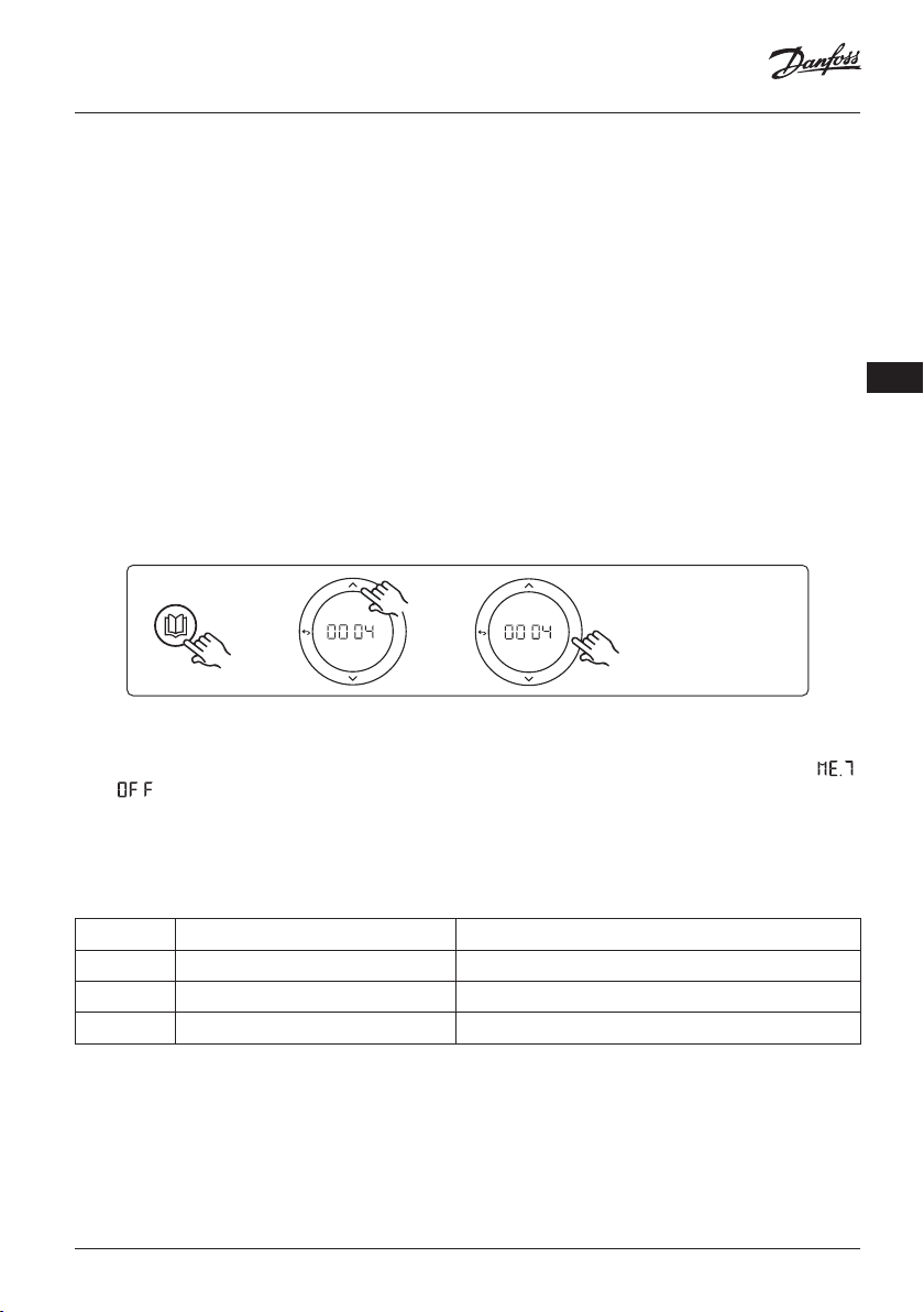
Installatiehandleiding Uitbreidingsmodule voor Danfoss Icon™ hoofdregelaar
Toepassing 0004: 2-pijps systeem met door warmtepomp geregelde omschakeling naar koelen.
Optioneel: dauwpuntsensor (aanbevolen), circulatiepomp en warmtevraagsignaal.
Toepassingsbeschrijving
Vloerverwarmingssysteem met automatische omschakeling voor koeling, geregeld door een warmtebron,
bijvoorbeeld een warmtepomp.
De warmtepomp levert het koelsignaal aan de Danfoss Icon™ hoofdregelaar wanneer de warmtepomp
naar de koelmodus gaat en de koelmodus dus wordt geactiveerd. Als de warmtepomp is aangesloten,
regelt het systeem de circulatiepomp en wordt die ingeschakeld wanneer er in ten minste 1 ruimte een
warmte- of koelvraag is.
Het verwarmingssignaal voor bijvoorbeeld een cv-ketel of warmtepomp wordt alleen geactiveerd als het
systeem zich in de verwarmingsmodus bevindt en er in ten minste 1 ruimte een warmtevraag is. Voor koeltoepassingen adviseren we altijd om een dauwpuntsensor in het systeem te installeren om vochtschade
aan de vloer en de installaties te voorkomen in gevallen waarbij de relatieve vochtigheid hoger is dan het
dauwpunt.
Instellingen
Geen instellingen nodig.
NL
APPLICATION
OK
OK
Instellingen op de thermostaat
Ruimten uitsluiten van koeling: Om een ruimte uit te sluiten van koeling – gewoonlijk in badkamers,
waar het toepassen van koeling oncomfortabel zou zijn – gaat u naar de thermostaat en stelt u menu
in op . Zie de installatiehandleiding van de thermostaat voor meer informatie.
Toepassingstestfunctie
Niet relevant.
Onderdelenlijst
Stand 1 Niet van toepassing 1 stuks warmtepomp
Stand 2 088U05XX / 088U06XX / 088U07XX 1 set Danfoss verdeler (type FHF of BasicPlus of SSM)
Stand 3 NC: 088H3110 / NO: 088H3111 xx stuks thermische actuator, 24 V TWA-A
Stand 4 088U0251 1 stuks dauwpuntsensor, type CF-DS
© Danfoss | FEC | 2018.12 | 91VIMDE20F / 088N2100
Page 92

Installatiehandleiding Uitbreidingsmodule voor Danfoss Icon™ hoofdregelaar
Toepassing 0005: 2-pijps systeem met hybride lucht/water-warmtepomp met
geïntegreerde HR-ketel (voorbeeld: Itho Cool Cube). Omschakeling verzocht
door referentiekamerthermostaat.
Optioneel: dauwpuntsensor (aanbevolen) en algemene stand-by.
Toepassingsbeschrijving
Vloerverwarmingssysteem waarbij de koeling wordt verzorgd met bijvoorbeeld Coolcube, die als warmteen koelbron wordt gebruikt.
Het Icon™ systeem regelt de warmte- en koelvraag door het betreffende relais (PWR1 en potentiaalvrij
relais) te activeren. Voor koeltoepassingen adviseren we altijd om een dauwpuntsensor in het systeem te
installeren om vochtschade aan de vloer en de installaties te voorkomen in gevallen waarbij de relatieve
vochtigheid hoger is dan het dauwpunt. Voordat het koelen van een ruimte wordt toegestaan, moet er aan
de volgende voorwaarden zijn voldaan:
• De referentieruimtetemperatuur moet hoger zijn dan het ruimtesetpoint + de koelhysterese.
• Geen enkele ruimte heeft binnen de neutrale tijd om warmte gevraagd.
• De dauwpuntsensor is niet actief/er bestaat geen kans op condensatie.
• De kamerthermostaat moet zijn ingeschakeld voor koeling (standaard = ingeschakeld).
De algemene stand-by is een potentiaalvrije ingang die kan worden gebruikt om het systeem op afstand in
te stellen op de algemene niet-thuis-modus, bijvoorbeeld via een gsm-module van een andere leverancier.
Als de ingang voor algemene stand-by actief is, krijgen alle ruimten een setpoint van 15 graden Celsius.
Instellingen
‘SET 1’ = stel de gewenste koelhysterese voor omschakeling in [+2 tot +4 K].
‘SET 2’ = stel de neutrale tijd in die moet verstrijken zonder actieve verwarming of koeling voordat een
omschakeling kan worden geactiveerd [3-6 uur].
APPLICATION
SETTINGS
92 | © Danfoss | FEC | 2018.12 VIMDE20F / 088N2100
OK
OK
OK
OK
OK
OK
OK
OK
Page 93

Installatiehandleiding Uitbreidingsmodule voor Danfoss Icon™ hoofdregelaar
Instellingen op de thermostaat
Ruimten uitsluiten van koeling: Om een ruimte uit te sluiten van koeling – gewoonlijk in badkamers,
waar het toepassen van koeling oncomfortabel zou zijn – gaat u naar de thermostaat en stelt u menu
in op . Zie de installatiehandleiding van de thermostaat voor meer informatie.
Een referentiekamerthermostaat selecteren: Om een thermostaat als referentiekamerthermostaat toe te
wijzen, gaat u naar de gewenste referentiekamerthermostaat en stelt u menu in op .
De eventueel geselecteerde thermostaat zal op basis van de werkelijke temperatuur in de ruimte bepalen
wanneer het systeem van de verwarmingsmodus naar de koelmodus gaat.
Er kan per systeem slechts één referentiethermostaat worden toegewezen. Als er meerdere thermostaten als
referentiethermostaat worden toegewezen, zal de laatst toegewezen thermostaat de eerdere referentiekamerthermostaat overschrijven, waardoor die eerdere thermostaat terug zal keren naar de normale werking.
Toepassingstestfunctie
Gebruik de installatietoets om naar het menu ‘Test’ te gaan.
De toepassingstest (APP test) is specifiek voor elke toepassing. De test is in stappen opgedeeld om ervoor te zorgen
dat alle componenten correct worden geïnstalleerd. Volg
de aangegeven procedure.
RUN
INSTALL
UNINSTALL
TEST
TEST NET
TEST APP
TEST FL
OK
O
Teststappen
Stap 1:3 Tijdens de eerste minuut van de test wordt de
warmtebron via ‘PWR1 output’ (PWR1-uitgang) ingesteld
op ‘heating mode’ (verwarmingsmodus). Controleer op
de gebruikersinterface van de warmtebron of verwarming
actief is.
Stap 2:3 Tijdens de tweede minuut van de test wordt de
warmtebron via ‘Relay output’ (Relaisuitgang) ingesteld op
‘cooling mode’ (koelmodus). Controleer op de gebruikersinterface van de warmtebron of koeling actief is.
Stap 3:3 Tijdens de derde minuut van de test wordt de
warmtebron ingesteld op ‘neutral mode’ (neutrale modus),
waarbij noch verwarming noch koeling actief is.
NL
Onderdelenlijst
Stand 1 Niet van toepassing 1 stuks, bijvoorbeeld Coolcube
Stand 2 088U05XX / 088U06XX / 088U07XX 1 set Danfoss verdeler (type FHF of BasicPlus of SSM)
Stand 3 NC: 088H3110 / NO: 088H3111 xx stuks thermische actuator, 24 V TWA-A
Stand 4 088U0251 1 stuks dauwpuntsensor, type CF-DS
Stand 5 Niet van toepassing
Extern relais (zet 230 V om naar potentiaalvrij relais) Wordt
niet door Danfoss geleverd
© Danfoss | FEC | 2018.12 | 93VIMDE20F / 088N2100
Page 94

Installatiehandleiding Uitbreidingsmodule voor Danfoss Icon™ hoofdregelaar
Toepassing 0006: 3-pijps systeem met koelregeling via een gemotoriseerde
afsluiter en een gezamenlijke retour, omschakelsignaal op verzoek van referentiekamerthermostaat.
Optioneel: dauwpuntsensor (aanbevolen), algemene stand-by en warmtevraagsignaalrelais.
Toepassingsbeschrijving
3-pijps vloerverwarmingssysteem met koeling die wordt geregeld via een gemotoriseerde afsluiter en een
gezamenlijke retour.
Het Icon™ systeem regelt de warmte- en koelvraag door het betreffende relais (PWR1 en PWR2) te activeren. Voor koeltoepassingen adviseren we altijd om een dauwpuntsensor in het systeem te installeren
om vochtschade aan de vloer en de installaties te voorkomen in gevallen waarbij de relatieve vochtigheid
hoger is dan het dauwpunt. Voordat het koelen van een ruimte wordt toegestaan, moet er aan de volgende
voorwaarden zijn voldaan:
• De referentieruimtetemperatuur moet hoger zijn dan het ruimtesetpoint + de koelhysterese.
• Geen enkele ruimte heeft binnen de neutrale tijd om warmte gevraagd.
• De dauwpuntsensor is niet actief/er bestaat geen kans op condensatie.
• De kamerthermostaat moet zijn ingeschakeld voor koeling (standaard = ingeschakeld).
De algemene stand-by is een potentiaalvrije ingang die kan worden gebruikt om het systeem op afstand in
te stellen op de algemene niet-thuis-modus, bijvoorbeeld via een gsm-module van een andere leverancier.
Als de ingang voor algemene stand-by actief is, krijgen alle ruimten een setpoint van 15 graden Celsius.
Instellingen
‘SET 1’ = stel de gewenste koelhysterese voor omschakeling in [+2 tot +4 K].
‘SET 2’ = stel de neutrale tijd in die moet verstrijken zonder actieve verwarming of koeling voordat een
omschakeling kan worden geactiveerd [3-6 uur].
APPLICATION
SETTINGS
94 | © Danfoss | FEC | 2018.12 VIMDE20F / 088N2100
OK
OK
OK
OK
OK
OK
OK
OK
Page 95

Installatiehandleiding Uitbreidingsmodule voor Danfoss Icon™ hoofdregelaar
Instellingen op de thermostaat
Ruimten uitsluiten van koeling: Om een ruimte uit te sluiten van koeling – gewoonlijk in badkamers,
waar het toepassen van koeling oncomfortabel zou zijn – gaat u naar de thermostaat en stelt u menu
in op . Zie de installatiehandleiding van de thermostaat voor meer informatie.
Een referentiekamerthermostaat selecteren: Om een thermostaat als referentiekamerthermostaat toe te
wijzen, gaat u naar de gewenste referentiekamerthermostaat en stelt u menu in op .
De eventueel geselecteerde thermostaat zal op basis van de werkelijke temperatuur in de ruimte bepalen
wanneer het systeem van de verwarmingsmodus naar de koelmodus gaat.
Er kan per systeem slechts één referentiethermostaat worden toegewezen. Als er meerdere thermostaten als
referentiethermostaat worden toegewezen, zal de laatst toegewezen thermostaat de eerdere referentiekamerthermostaat overschrijven, waardoor die eerdere thermostaat terug zal keren naar de normale werking.
Toepassingstestfunctie
Gebruik de installatietoets om naar het menu ‘Test’ te gaan.
De toepassingstest (APP test) is specifiek voor elke toepassing. De test is in stappen opgedeeld om ervoor te zorgen
dat alle componenten correct worden geïnstalleerd. Volg
de aangegeven procedure.
RUN
INSTALL
UNINSTALL
TEST
TEST NET
TEST APP
TEST FL
OK
O
Teststappen
Stap 1:2 Tijdens de eerste minuut van de test wordt de
AMZ 113 afsluiter via ‘PWR1 output going ON’ (Inschakeling PWR1-uitgang) ingesteld op ‘heating mode’ (verwarmingsmodus). Controleer op de afsluiter/servomotor of de
geselecteerde stand correct is voor ‘heating’ (verwarming).
Stap 2:2 Tijdens de tweede minuut van de test wordt de
AMZ 113 afsluiter via ‘PWR1 output going OFF’ (Uitschakeling PWR1-uitgang) ingesteld op ‘cooling mode’
(koelmodus). Controleer op de afsluiter/servomotor of de
geselecteerde stand correct is voor ‘cooling’ (koeling).
NL
Onderdelenlijst
Stand 1 DN 15: 082G5511 DN 20: 088G5512 1 stuks AMZ 113 (3-wegafsluiter)
Stand 2 088U05XX / 088U06XX / 088U07XX 1 set Danfoss verdeler (type FHF of BasicPlus of SSM)
Stand 3 NC: 088H3110 / NO: 088H3111 xx stuks thermische actuator, 24 V TWA-A
Stand 4 088U0251 1 stuks dauwpuntsensor, type CF-DS
© Danfoss | FEC | 2018.12 | 95VIMDE20F / 088N2100
Page 96

Installatiehandleiding Uitbreidingsmodule voor Danfoss Icon™ hoofdregelaar
Toepassing 0007: 3-pijps systeem met koelregeling via thermische actuatoren
en een gezamenlijke retour, geregeld door een referentiekamerthermostaat.
Optioneel: dauwpuntsensor (aanbevolen), algemene stand-by, pomprelais en warmtevraagsignaal.
Toepassingsbeschrijving
3-pijps vloerverwarmingssysteem met koeling die wordt geregeld via thermische actuatoren en een gezamenlijke retour.
Het Icon™ systeem regelt de warmte- en koelvraag door de betreffende uitgang (M1 en M2) te activeren.
Voor koeltoepassingen adviseren we altijd om een dauwpuntsensor in het systeem te installeren om
vochtschade aan de vloer en de installaties te voorkomen in gevallen waarbij de relatieve vochtigheid
hoger is dan het dauwpunt. Voordat het koelen van een ruimte wordt toegestaan, moet er aan de volgende
voorwaarden zijn voldaan:
• De referentieruimtetemperatuur moet hoger zijn dan het ruimtesetpoint + de koelhysterese.
• Geen enkele ruimte heeft binnen de neutrale tijd om warmte gevraagd.
• De dauwpuntsensor is niet actief/er bestaat geen kans op condensatie.
• De kamerthermostaat moet zijn ingeschakeld voor koeling (standaard = ingeschakeld).
De algemene stand-by is een potentiaalvrije ingang die kan worden gebruikt om het systeem op afstand in
te stellen op de algemene niet-thuis-modus, bijvoorbeeld via een gsm-module van een andere leverancier.
Als de ingang voor algemene stand-by actief is, krijgen alle ruimten een setpoint van 15 graden Celsius.
Instellingen
‘SET 1’ = stel de gewenste koelhysterese voor omschakeling in [+2 tot +4 K].
‘SET 2’ = stel de neutrale tijd in die moet verstrijken zonder actieve verwarming of koeling voordat een
omschakeling kan worden geactiveerd [3-6 uur].
APPLICATION
SETTINGS
96 | © Danfoss | FEC | 2018.12 VIMDE20F / 088N2100
OK
OK
OK
OK
OK
OK
OK
OK
Page 97

Installatiehandleiding Uitbreidingsmodule voor Danfoss Icon™ hoofdregelaar
Instellingen op de thermostaat
Ruimten uitsluiten van koeling: Om een ruimte uit te sluiten van koeling – gewoonlijk in badkamers,
waar het toepassen van koeling oncomfortabel zou zijn – gaat u naar de thermostaat en stelt u menu
in op . Zie de installatiehandleiding van de thermostaat voor meer informatie.
Een referentiekamerthermostaat selecteren: Om een thermostaat als referentiekamerthermostaat toe te
wijzen, gaat u naar de gewenste referentiekamerthermostaat en stelt u menu in op .
De eventueel geselecteerde thermostaat zal op basis van de werkelijke temperatuur in de ruimte bepalen
wanneer het systeem van de verwarmingsmodus naar de koelmodus gaat.
Er kan per systeem slechts één referentiethermostaat worden toegewezen. Als er meerdere thermostaten als
referentiethermostaat worden toegewezen, zal de laatst toegewezen thermostaat de eerdere referentiekamerthermostaat overschrijven, waardoor die eerdere thermostaat terug zal keren naar de normale werking.
Toepassingstestfunctie
Gebruik de installatietoets om naar het menu ‘Test’ te gaan.
De toepassingstest (APP test) is specifiek voor elke toepassing. De test is in stappen opgedeeld om ervoor te zorgen
dat alle componenten correct worden geïnstalleerd. Volg
de aangegeven procedure.
RUN
INSTALL
UNINSTALL
TEST
TEST NET
TEST APP
TEST FL
OK
O
Teststappen
Stap 1:3 Tijdens de eerste 5 minuten van de test
worden de uitgangen 1 ingesteld op ‘ON’ (AAN) =
verwar mingsmodus/aan de kant van warme stroming (een openingstijd tot 3 minuten is normaal).
Stap 2:3 Tijdens de volgende 5 minuten van de test
wor den de uitgangen 1 ingesteld op ‘OFF’ (UIT) en
worden de uitgangen 2 ingesteld op ‘ON’ (AAN) =
koelmodus/ aan de kant van koude stroming (een
openingstijd tot 3 minuten is normaal).
Stap 3:3 Tijdens de laatste 5 minuten van de test
moeten alle uitgangen (1 en 2) sluiten.
NL
Onderdelenlijst
Stand 1 DN 15: 013G3094 DN 20: 013G3016 2 stuks RA-C afsluiter
Stand 2 088U05XX / 088U06XX / 088U07XX 1 set Danfoss verdeler (type FHF of BasicPlus of SSM)
Stand 3 NC: 088H3110 / NO: 088H3111 xx stuks thermische actuator, 24 V TWA-A
Stand 4 088U0251 1 stuks dauwpuntsensor, type CF-DS
Stand 5a & 5b 088H3110 2 stuks thermische actuator, 24 V TWA-A
© Danfoss | FEC | 2018.12 | 97VIMDE20F / 088N2100
Page 98

Installatiehandleiding Uitbreidingsmodule voor Danfoss Icon™ hoofdregelaar
Toepassing 0008: 3-pijps systeem met koelregeling via servomotoren en een
gezamenlijke retour, geregeld door een referentiekamerthermostaat.
Optioneel: dauwpuntsensor (aanbevolen), algemene stand-by, pomprelais en warmtevraagsignaal.
Toepassingsbeschrijving
3-pijps vloerverwarmingssysteem met koeling die wordt geregeld via servomotoren en een gezamenlijke
retour.
Het Icon™ systeem regelt de warmte- en koelvraag door de betreffende uitgang (PWR1 en potentiaalvrij
relais) te activeren. Voor koeltoepassingen adviseren we altijd om een dauwpuntsensor in het systeem te
installeren om vochtschade aan de vloer en de installaties te voorkomen in gevallen waarbij de relatieve
vochtigheid hoger is dan het dauwpunt. Voordat het koelen van een ruimte wordt toegestaan, moet er aan
de volgende voorwaarden zijn voldaan:
• De referentieruimtetemperatuur moet hoger zijn dan het ruimtesetpoint + de koelhysterese.
• Geen enkele ruimte heeft binnen de neutrale tijd om warmte gevraagd.
• De dauwpuntsensor is niet actief/er bestaat geen kans op condensatie.
• De kamerthermostaat moet zijn ingeschakeld voor koeling (standaard = ingeschakeld)
Als er geen warmte- of koelvraag aanwezig is, sluiten de twee afsluiters (AMZ 112).
De algemene stand-by is een potentiaalvrije ingang die kan worden gebruikt om het systeem op afstand in
te stellen op de algemene niet-thuis-modus, bijvoorbeeld via een gsm-module van een andere leverancier.
Als de ingang voor algemene stand-by actief is, krijgen alle ruimten een setpoint van 15 graden Celsius.
Instellingen
‘SET 1’ = stel de gewenste koelhysterese voor omschakeling in [+2 tot +4 K].
‘SET 2’ = stel de neutrale tijd in die moet verstrijken zonder actieve verwarming of koeling voordat een
omschakeling kan worden geactiveerd [3-6 uur].
APPLICATION
SETTINGS
98 | © Danfoss | FEC | 2018.12 VIMDE20F / 088N2100
OK
OK
OK
OK
OK
OK
OK
OK
Page 99

Installatiehandleiding Uitbreidingsmodule voor Danfoss Icon™ hoofdregelaar
Instellingen op de thermostaat
Ruimten uitsluiten van koeling: Om een ruimte uit te sluiten van koeling – gewoonlijk in badkamers,
waar het toepassen van koeling oncomfortabel zou zijn – gaat u naar de thermostaat en stelt u menu
in op . Zie de installatiehandleiding van de thermostaat voor meer informatie.
Een referentiekamerthermostaat selecteren: Om een thermostaat als referentiekamerthermostaat toe te
wijzen, gaat u naar de gewenste referentiekamerthermostaat en stelt u menu in op .
De eventueel geselecteerde thermostaat zal op basis van de werkelijke temperatuur in de ruimte bepalen
wanneer het systeem van de verwarmingsmodus naar de koelmodus gaat.
Er kan per systeem slechts één referentiethermostaat worden toegewezen. Als er meerdere thermostaten als
referentiethermostaat worden toegewezen, zal de laatst toegewezen thermostaat de eerdere referentiekamerthermostaat overschrijven, waardoor die eerdere thermostaat terug zal keren naar de normale werking.
Toepassingstestfunctie
Gebruik de installatietoets om naar het menu ‘Test’ te gaan.
De toepassingstest (APP test) is specifiek voor elke toepassing. De test is in stappen opgedeeld om ervoor te zorgen
dat alle componenten correct worden geïnstalleerd. Volg
de aangegeven procedure.
RUN
INSTALL
UNINSTALL
TEST
TEST NET
TEST APP
TEST FL
OK
O
Teststappen
Stap 1:3 Tijdens de eerste minuut van de test wordt de
AMZ 112 afsluiter aan de kant van de warme stroming
via ‘PWR1 output going ON’ (Inschakeling PWR1-uitgang)
ingesteld op ‘heating mode’ (verwarmingsmodus). Controleer op de afsluiter/servomotor of de geselecteerde stand
correct is voor ‘heating’ (verwarming).
Stap 2:3 Tijdens de tweede minuut van de test wordt de
AMZ 112 afsluiter via ‘PWR1 output going OFF’ (Uitschakeling PWR1-uitgang) en ‘Relay output going ON’
(Inschakeling relaisuitgang) ingesteld op ‘cooling mode’
(koelmodus). Controleer op de afsluiter/servomotor of de
geselecteerde stand correct is voor ‘cooling’ (koeling).
Stap 3:3 Tijdens de laatste minuut van de test worden
beide AMZ 112 afsluiters gesloten.
NL
Onderdelenlijst
Stand 1a & 1b DN 15: 082G5511 DN 20: 082G5512 2 stuks AMZ 112
Stand 2 088U05XX / 088U06XX / 088U07XX 1 set Danfoss verdeler (type FHF of BasicPlus of SSM)
Stand 3 NC: 088H3110 / NO: 088H3111 xx stuks thermische actuator, 24 V TWA-A
Stand 4 088U0251 1 stuks dauwpuntsensor, type CF-DS
© Danfoss | FEC | 2018.12 | 99VIMDE20F / 088N2100
Page 100

Installatiehandleiding Uitbreidingsmodule voor Danfoss Icon™ hoofdregelaar
Toepassing 0009: 4-pijps systeem met 6-wegafsluiter, automatische omschakeling voor koeling op basis van een referentiekamerthermostaat. (Hiervoor is een
externe 24 V AC PSU vereist.)
Optioneel: dauwpuntsensor (aanbevolen), afsluitfunctie en algemene stand-by.
Toepassingsbeschrijving
Vloerverwarmingssysteem met automatische omschakeling voor koeling via een 6-weg omschakelafsluiter
die wordt geregeld door een referentiekamerthermostaat.
Het systeem kan worden geconfigureerd met een optionele afsluitfunctie via een Danfoss AMZ 112 2-weg
kogelafsluiter en algemene stand-by. Voor koeltoepassingen adviseren we altijd om een dauwpuntsensor
in het systeem te installeren om vochtschade aan de vloer en de installaties te voorkomen in gevallen
waarbij de relatieve vochtigheid hoger is dan het dauwpunt. Voordat het koelen van een ruimte wordt
toegestaan, moet er aan de volgende voorwaarden zijn voldaan:
• De referentieruimtetemperatuur moet hoger zijn dan het ruimtesetpoint + de koelhysterese.
• Geen enkele ruimte heeft binnen de neutrale tijd om warmte gevraagd.
• De dauwpuntsensor is niet actief/er bestaat geen kans op condensatie.
• De kamerthermostaat moet zijn ingeschakeld voor koeling (standaard = ingeschakeld).
Als er geen warmte- of koelvraag aanwezig is, sluit de afsluiter.
De algemene stand-by is een potentiaalvrije ingang die kan worden gebruikt om het systeem op afstand in
te stellen op de algemene niet-thuis-modus, bijvoorbeeld via een gsm-module van een andere leverancier.
Als de ingang voor algemene stand-by actief is, krijgen alle ruimten een setpoint van 15 graden Celsius.
Instellingen
‘SET 1’ = stel de gewenste koelhysterese voor omschakeling in [+2 tot +4 K].
‘SET 2’ = stel de neutrale tijd in die moet verstrijken zonder actieve verwarming of koeling voordat een
omschakeling kan worden geactiveerd [3-6 uur].
APPLICATION
SETTINGS
100 | © Danfoss | FEC | 2018.12 VIMDE20F / 088N2100
OK
OK
OK
OK
OK
OK
OK
OK
 Loading...