

Page 1
Data sheet
MAKE UP LINE Substations
Make Up substations for secondary heating
circuits with heat load up to 8000 KW, and the
static height up to 60 mwc
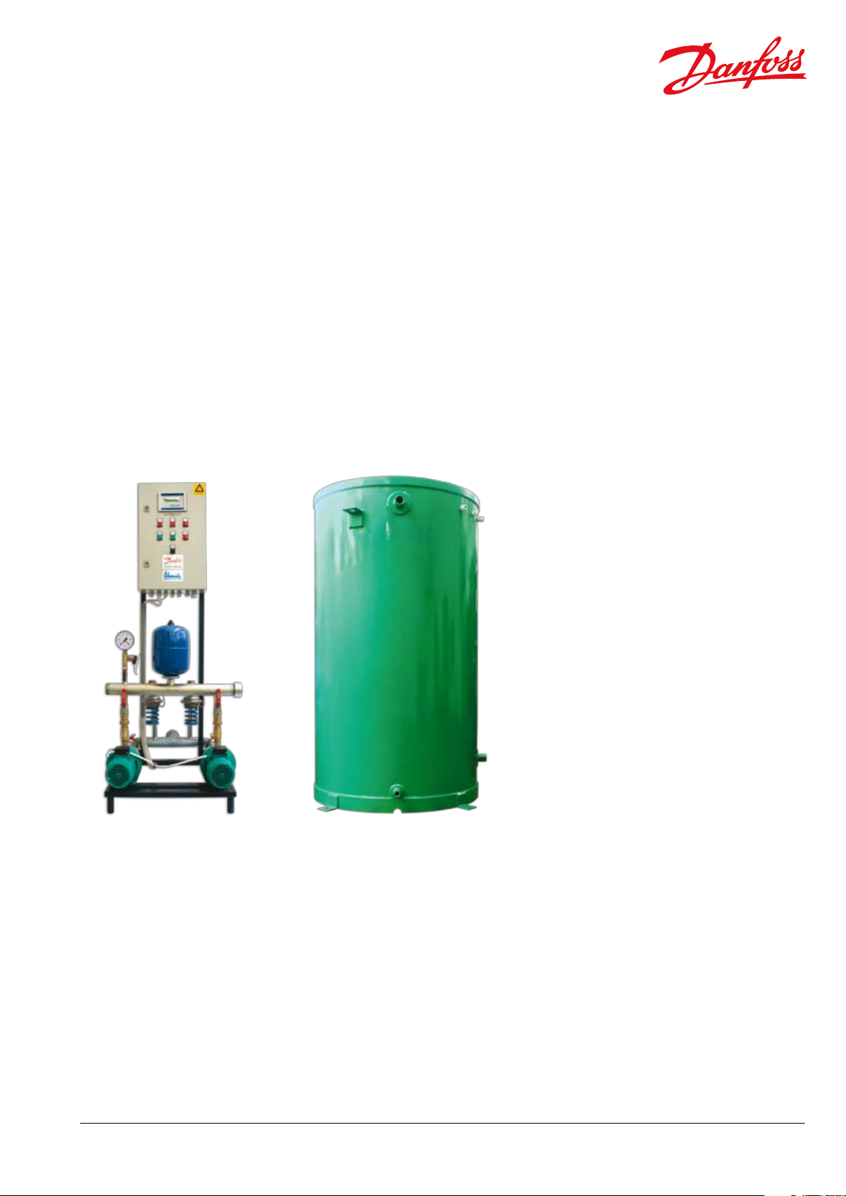
Compact substations for water expansion control in heating installations
(secondary side), with atmospheric tank and automatic make / fill up functions
Designed for floor mounting
Description
Function
The Make Up system has the function to discharge
the soft water into an atmospheric tank via pressure
relief valve(s) if the heating circuit develops a
pressure value over the maximum set value or has
the function to fill up the heating installation circuit
via make up pump(s) if the pressure decreases
below the minimum set value. The volume of filling
up water or the leakage water from heating circuit
is automatically replaced in water tank via solenoid
valve.
Also, the system:
- is able to protect the pump in case of water
lack;
- can assure a sequential start of pumps;
- is able to stop functioning pumps in case of pipe
breaking;
- can make automate switching on the second
pump in case of failure function of the first;
- assures the permanent monitoring of the water
level in the atmospheric tank (minimum, normal
and maximum);
- assures the filtering of water.
DH -SMT/ PL
Purpose
This system is suitable for maintaining the pressure
between an overpressure given by water dilatation
and an underpressure limit given by loses of water
from different reasons in secondary heating
circuit.
Installation
The MAKE UP LINE is a range of systems mounted
on the secondary side of district heating systems
or thermal plants with a maximum temperature of
115 oC and PN 6 / PN 10 in the flow circuit.
VD.EH.D1.02 © Danfoss 02/2009
Construction
The construction is compact, simple and easy to
use. The pipes are corrosion protected through
galvanic treatment both on the inside and on the
outside. The components selection (size and type)
is made using a calculation method developed by
Schmidt-Bretten Technology, member of Danfoss
Group.
Specific advantages
- protection of the heating circuit at overpressure
- automatic control of pressure in heating circuit
- monitoring and remote control
- a unitary system, ready to be mounted in site, easy
to install for a minimal location site
- very good performances when coupling with
Schmidt heating substations
1
Page 2
Data sheet MAKE-UP LINE Substations
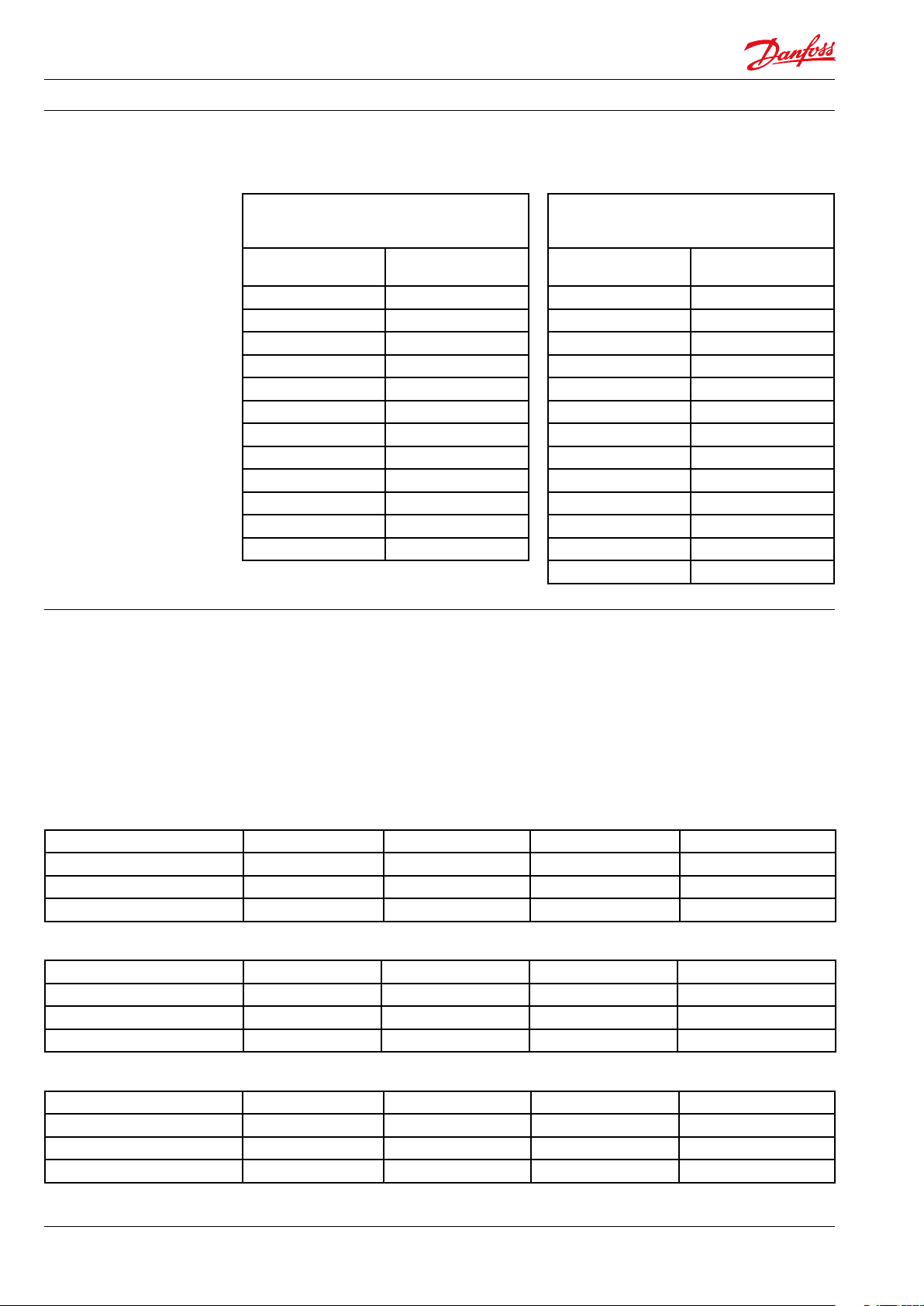
Ordering
The Make Up substation is made up of the pump group (see Table 1) and of the Storage tank (see
Table 2) that are ordered separately.
Pump group range and their ordering
Table 1
codes
Typ e Code no
Atmospheric storage tank range and their
Storage tank volume
Table 2
ordering codes
Code no
[liters]
EXP 203 004F4094
EXP 204 004F4095
EXP 205 004F4096
EXP 206 004F4097
EXP 403 004F4098
EXP 404 004F4099
EXP 405 0 04F 4100
EXP 406 00 4F4101
EXP 802 00 4F 4102
EXP 803 00 4F 4103
EXP 804 004F4104
EXP 805 00 4F 4105
200 CT K0101
300 CT K0102
400 CTK0103
500 CTK010 4
800 CTK 0105
100 0 C TK0106
120 0 CT K0107
150 0 CTK010 8
2000 CTK0109
2500 C T K0 110
3000 C T K 0111
3500 C T K 011 2
4000 C T K 011 3
Technical parameters:
WORKING MEDIUM (heating circuit)
Maximum temperature T
Nominal pressure PN 6 / PN 10
= 115oC
max
MAKE UP SOURCE
Maximum temperature T
Nominal pressure PN 6 / PN 10
max
= 80oC
Electrical supply 3~ 400 V / 50 Hz
Table 3 Low power Make up substations characteristics
Typ e EXP 203 EXP 204 EXP 205 EXP 206
Pressure relief controller - range 1 ÷ 4.5 bar 1 ÷ 4.5 bar 3 ÷ 11 bar 3 ÷ 11 bar
Electrical power [kW] 2 x 0.55 2 x 0.55 2 x 0.75 2 x 1.1
DN collectors DN 40 DN 40 DN 40 DN 40
Table 4 Medium power Make up substations characteristics
Typ e EXP 403 EXP 404 EXP 405 EXP 406
Pressure relief controller - range 1 ÷ 4.5 bar 1 ÷ 4.5 bar 3 ÷ 11 bar 3 ÷ 11 bar
Electrical power [kW] 2 x 0.55 2 x 0.75 2 x 1.1 2 x 1.5
DN collectors DN 50 DN 50 DN 50 DN 50
Table 5 High power Make up substations characteristics
Typ e EXP 802 EXP 803 EXP 804 EXP 805
Pressure relief controller - range 1 ÷ 4.5 bar 1 ÷ 4.5 bar 1 ÷ 4.5 bar 3 ÷ 11 bar
Electrical power [kW] 2 x 0.75 2 x 1.1 2 x 1.5 2 x 1.85
DN collectors DN 65 DN 65 DN 65 DN 65
2
VD.EH.D1.02 © Danfoss 02/2009
DH -SMT/ PL
Page 3
Data sheet MAKE-UP LINE Substations
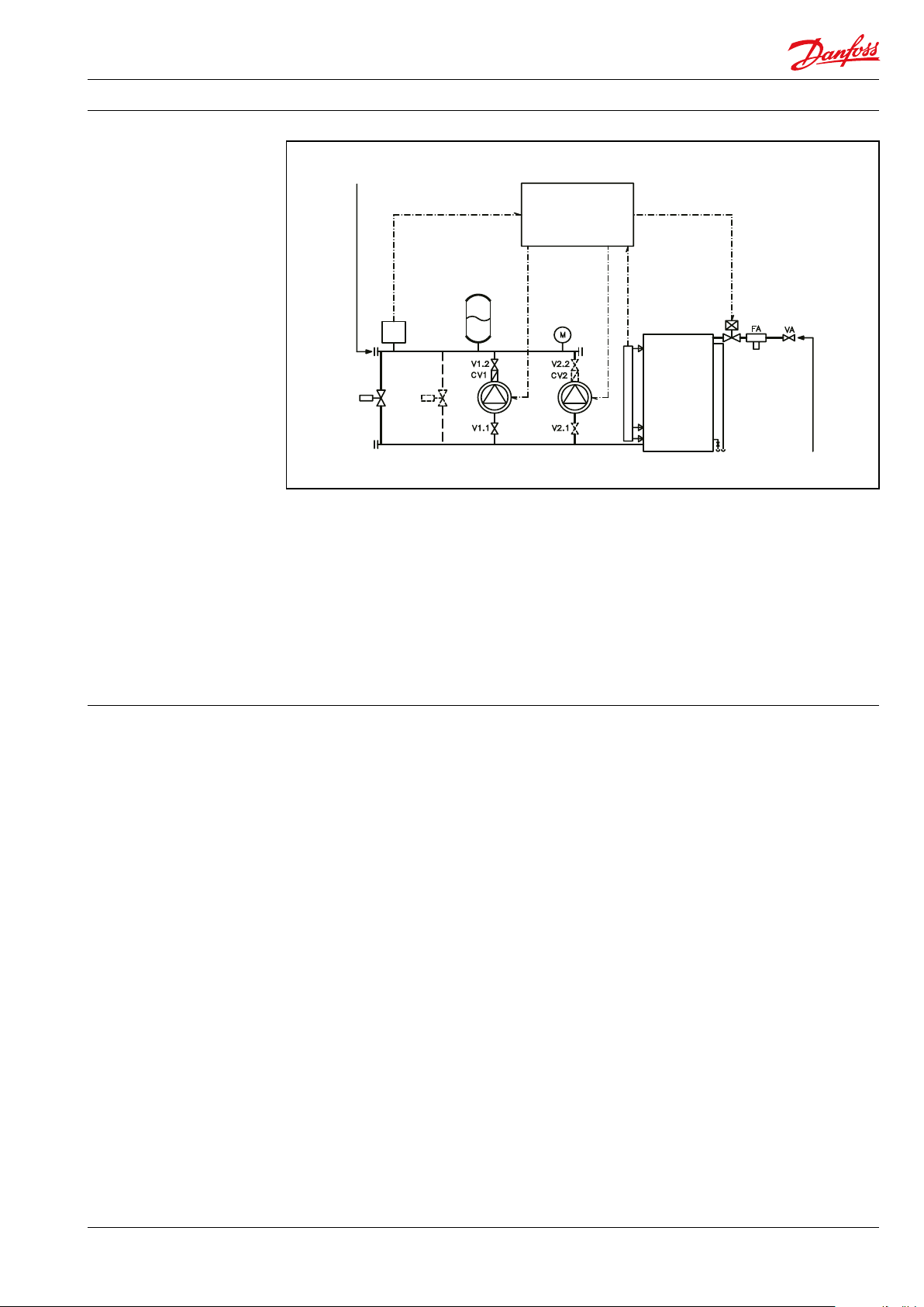
VD1
V1.1
VD2
PA1
V1.2
CV1
P
M
VTM
V2.1
V2.2
CV2
PA2 WTL
EVM
ELP
VA
FA
Design:
R1 (R2): heating
installation connection
Components:
PA1 (PA2) Make up pump – one or two pieces
VD1 (VD2) Excess pressure valve
(pressure relief controller)
– one or two pieces
EVM Solenoid valve
P Pressure sensor
L Level switches
ELP Electric and control panel
R3: soft water
connection
V1 (V2) Shut off valve – pump circuit
VA Shut off valve – fill up circuit
CV1 (CV2) Check valve
FA Strainer
M Manometer
WT Atmospheric water tank
VTM Closed pressure vessel
(against pressure shocks)
Main functions:
Specific restriction
- Maintains heating system pressure in very strict
limits;
- Protects the heating circuit against
overpressure;
- Fills up and makes up the heating circuit;
- Recovers the discharged soft water from the
heating system;
- Monitors the water leakage and, in case of pipe
breaking, stops the pumps;
- Monitors the water level in atmospheric tank
(minimum, normal and maximum);
- Fills up water tank;
- Protects pump in case of water lack;
- Communicates via standardized RS485 optional
modules
- The soft water available flow should be larger than
the necessary make up flow for heating circuit.
DH -SMT/ PL
VD.EH.D1.02 © Danfoss 02/2009
3
Page 4

Data sheet WATER LINE Substations
EXP 203
EXP 204
EXP 205
EXP 206
EXP 403
EXP 404
EXP 405
EXP 406
EXP 802
EXP 803
EXP 804
EXP 805
0
10
20
30
40
50
60
70
80
0 1000 2000 3000 4000 5000 6000 7000 8000
p st [wmc]
Q [kW]
Sizing Make Up substation The pump group is selected from low, medium or
high range depending either on the heating power
of the heating circuit deserved (Figure 1) or on the
maximum thermal agent flow rate (Figure 2). A
selection decision derives from the desired
maximum pressure in the secondary heating
circuit.
Figure 1
Fast selection for pump group by heat load and static pressure
4
VD.EH.D1.02 © Danfoss 02/2009
DH -SMT/ PL
Page 5

Data sheet WATER LINE Substations
EXP 204
EXP 206
EXP 203
EXP 205
EXP 403
EXP 404
EXP 405
EXP 406
EXP 802
EXP 803
EXP 804
EXP 805
0
10
20
30
40
50
60
70
80
0 2 4 6 8 10 12
q [cm/h] / one head pump
p st [wmc]
0
500
1000
1500
2000
2500
3000
3500
4000
4500
5000
5500
6000
6500
7000
7500
8000
0 500 1000 1500 2000 2500 3000 3500 4000 4500 5000 5500 6000 6500 7000 7500 8000
standard
applications
special
application
(for small networks)
Q [kW]
Expansion volume [liters]
Figure 2
Fast selection of pump group by flow rate (for one pump) and static pressure
The volume of expansion tank is calculated
according to water volume from heating circuit and
dilatation coefficient. For a fast selection of the
expansion tank, can use the diagram - Figure 3. This
diagram can be used either for standard application
or for special applications (short networks with
small diameter and with large water velocity in
pipes). When the resulting volume from this
diagram is larger than the selected standard
storage tank volume, two or more tanks should be
mounted in series.
Figure 3
Fast selection for atmospheric expansion tank
DH -SMT/ PL
VD.EH.D1.02 © Danfoss 02/2009
5
Page 6

Data sheet WATER LINE Substations
R3: soft water connection
800 mm
R3
800 mm
H
h
(R2): heating
instalation
connection
R1
WT
ELP
PA 1
VTM
WT
additional
VD1
Ordering examples:
Mounting hydraulic
recommended sketch:
Dimensions:
Example 1
A Make Up substation is selected to deserve a
secondary heating circuit for a small network, with
a maximum heat load of 2000 kW and a maximum
25 mwc static pressure. From the heat load sizing
diagram (Figure 1), the EXP 203 substation is
suitable (code no is 004F4094). From the storage
tank selection diagram (Figure 3), an atmospheric
tank with 1000 liters capacity is recommended for
a special application (code no CTK0106).
Example 2
A Make Up substation is selected to deserve a
secondary standard heating circuit with a maximum
10 m3/h flow rate and a maximum 20 mwc static
pressure. From the flow rate sizing diagram (Figure
2), which is for one head pump, for 5.5 m3/h the
EXP 403 substation is suitable (code no is 004F4098).
From the heat load sizing diagram (Figure 1), for
EXP 403 and static pressure of 20 mwc, we have
4500 kW. From the storage tank selection diagram
(Figure 3), an atmospheric tank with 3500 liters
capacity is recommended for a standard application
(code no CTK0112).
Weight:
This design has informative character
Typ e EXP
203
EXP
204
Weight
[kg] 50 50 60 60
Typ e EXP
403
EXP
404
Weight
[kg] 50 60 60 70
Typ e EXP
Weight
802
50 60 70 70
EXP
803
[kg]
EXP
205
EXP
405
EXP
804
EXP
206
EXP
406
EXP
805
6
VD.EH.D1.02 © Danfoss 02/2009
DH -SMT/ PL
Page 7

Data sheet WATER LINE Substations
R5
De x s
SIDE VIEW
FRONT VIEW
R3
R2
Storage tank:
R1 connection with soft water source
R2(3) - connection with pump group
R4 = overflow passage
R5 = emptying connection
Code no Storage
CT K0101 200 550×2.5 100 0 900 ¾” 1” 1” ½” 48
CT K0102 300 550×2.5 15 00 140 0 ¾” 1” 1” ½” 66
CTK0103 400 600×2.5 150 0 140 0 ¾” 1” 1” ½” 73
CT K0104 500 700×2.5 15 00 140 0 ¾” 1” 1” ½” 88
CT K0105 800 850×3 150 0 14 00 ¾” 1” 1” ½” 133
CT K0106 100 0 850×3 2000 19 00 1” 1 ½” 1 ¼” ½” 168
CT K0107 120 0 850×3 2200 2100 1” 1 ½” 1 ¼” ½” 181
CT K0108 15 00 1000×3 2000 190 0 1” 1 ½” 1 ¼” ½” 203
CT K0109 2000 11 0 0× 3 2200 2100 1 ½” 1 ½” 1 ½” ½” 246
C T K 011 0 2500 125 0× 3 2200 210 0 1 ½” 1 ½” 1 ½” ½” 287
C T K 0111 3000 125 0× 3 2500 2400 1 ½” 2” 1 ½” ½” 318
C T K 0112 3500 135 0× 3 2500 2400 1 ½” 2” 1 ½” ½” 349
C T K 0113 4000 15 00 ×4 2500 2400 1 ½” 2” 2” ½” 529
capacity
[l]
ΦDe×s
[mm]
H [mm] h [mm] R1 R2 (R3) R4 R5 Weight
empty
[kg]
DH -SMT/ PL
VD.EH.D1.02 © Danfoss 02/2009
7
Page 8

Data sheet WATER LINE Substations
Danfoss Schmidt-Bretten Technology SRL · 208 Oltenitei Drive · Popesti-Leordeni 077160 · Ilfov · Romania
Tel.: +4031 222 20 10 · Fax: +4031 222 22 99 · secretariat@schmidt.ro
8
VD.EH.D1.02
Produce d by Danfoss A/S © 02/20 09
 Loading...