

Page 1
Data sheet
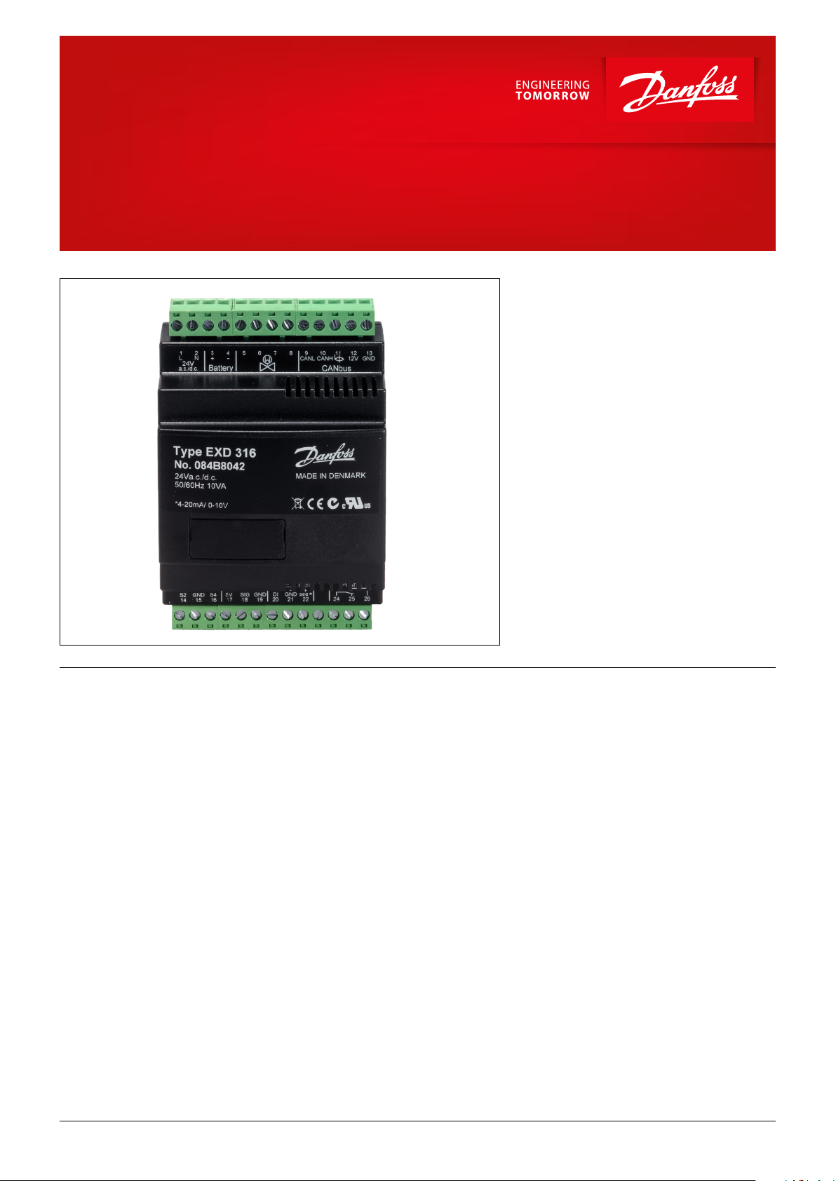
Superheat Controller
Type EXD 316
EXD 316 is a superheat controller for the stepper
motor valve that can be used where there are
requirements for accurate control of superheat in
connection with refrigeration.
The controller and valve can be used where
there are requirements for accurate control of
superheat in connection with refrigeration.
Applications:
• Processing plant (water chillers)
• Cold store (air coolers)
• A/C plant
• Heat pumps
• Air conditioning
Benets • The superheat is regulated to the lowest
possible value.
• The evaporator is charged optimally – even
when there are great variations of load and
suction pressure.
Main features
• Regulation of superheat
• MOP function
• ON/OFF input for start/stop of regulation
• Relay output to alarm
• Energy savings – the adaptive regulation of
the refrigerant injection ensures optimum
utilisation of the evaporator and thus a high
suction pressure.
• CANbus communication
• Safety features and
• Alarm indications
© Danfoss | DCS (sw) | 2017.01
DKRCC.PD.RT0.A1.02 | 1
Page 2

Data sheet | Superheat controller type EXD 316
Contents Pages
Applications..................................................................................................................................................3
Function overview ..........................................................................................................................................3
Data ...........................................................................................................................................................4
Accessories ...................................................................................................................................................4
Ordering ......................................................................................................................................................4
Dimensions ..................................................................................................................................................4
Connections .................................................................................................................................................5
Conguration ................................................................................................................................................6
Installation ...................................................................................................................................................7
Data communication .......................................................................................................................................7
Installation sensors ..........................................................................................................................................8
Start of controller............................................................................................................................................9
Settings and checks to be made before start ............................................................................................................9
Op ........................................................................................................................................................... 10
Operation .................................................................................................................................................. 11
Types of regulation ........................................................................................................................................ 12
Manually operating the valve ............................................................................................................................ 13
Finding the optimum settings ........................................................................................................................... 14
If the superheat uctuates ............................................................................................................................... 14
Troubleshooting ........................................................................................................................................... 15
Alarms ...................................................................................................................................................... 15
Appendix I.................................................................................................................................................. 16
- Menu survey ............................................................................................................................................ 16
- Survey of functions .................................................................................................................................... 18
Appendix II ................................................................................................................................................. 21
- General information to CANbus communication via a PLC etc. ................................................................................. 21
- EXD 316 – Parameter identication (CANbus) ..................................................................................................... 22
Installation considerations ............................................................................................................................... 23
List of literature ............................................................................................................................................ 23
Acronyms and abbreviations used in this manual:
LOC Loss of charge indication
SH Superheat
MOP Maximum operating pressure
MSS Minimum stable superheat
PNU Parameter number
Te Saturated suction temperature
Pe Evaporator pressure
S2 Evaporator temperature
S4 Evaporator outlet temperature
OD Opening degree
EEV Electronic expansion valve
∆Tm Temperature dierence between media temperature and evaporating temperature
© Danfoss | DCS (sw) | 2017.01
DKRCC.PD.RT0.A1.02 | 2
Page 3
EXD 316
Data sheet | Superheat controller type EXD 316
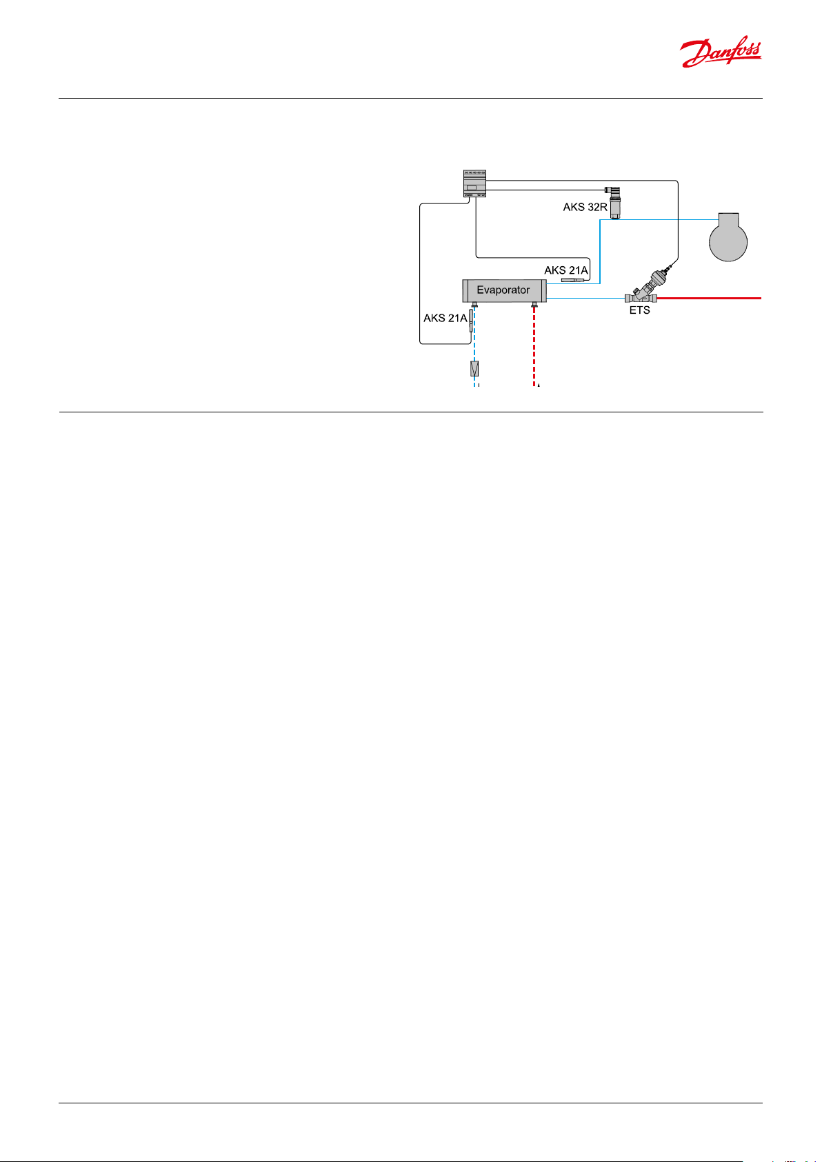
Applications
The following gives an idea of the application scope of the
EXD 316 controller.
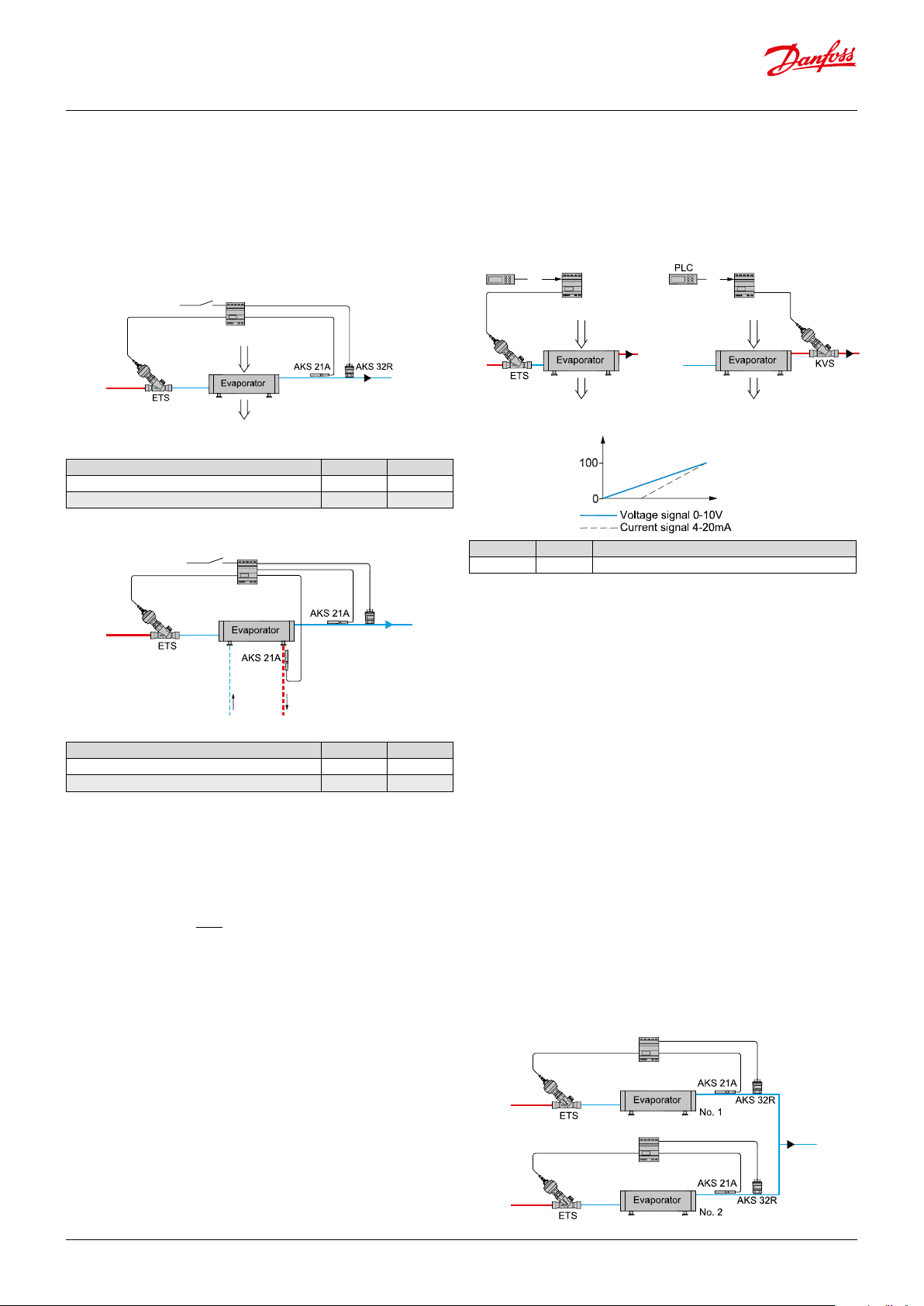
Water chiller using direct expansion
The most common application is water chillers using direct
expansion. The regulation can be single loop using an AKS 32R
pressure transmitter to measure evaporator pressure and an S2
sensor to measure superheated gas. If double loop regulation is
used, the S4 sensor should be located at the water outlet pipe to
measure the leaving water temperature. It is recommended to
start with factory settings.
The application diagram shows the use of EXD 316 as a
superheat controller, where temperature sensor AKS 21A and
pressure transmitter AKS 32R have been shown as an example.
Function overview
Minimum Stable Superheat (MSS)
The controller will search for the minimum stable superheat
between an upper and lower boundry. If the superheat has been
stable for a period, the superheat reference is decreased. If the
superheat becomes unstable, the reference is raised again. This
process continues as long as the superheat is within the bounds
set by the user. The purpose of this is to search for the lowest
possible superheat that can be obtained while still maintaining a
stable system. The superheat reference can also be xed, in which
case this function is disabled.
Maximum Operating Pressure (MOP)
In order to reduce the strain of the compressor, a maximum
operating pressure can be set. If the pressure comes above this
limit, the controller will control the valve to provide a lower
pressure instead of a low superheat. The limit for this function
is usually a xed pressure, but it is possible to oset the limit
temporarily.
Stand-alone function
EXD 316 is designed to operate in conjunction with a system
master controller, which will control the EXD 316 via CANBUS or
analog signal. It is however possible to use it in a standalone mode
using one temperature and one pressure transducer.
Danfoss
84N386.10
Manual Control as a valve driver
The valve can be controlled manually by setting the desired
operating degree using CANBUS. Alternatively, the controller may
also be started and stopped externally using the analog signal 4 to
20 mA/0 to 10 V d.c., /1 to 5 V d.c.
Forced opening during startup
In some applications it is necessary to open the valve quickly when
the compressor turns on to prevent suction pressure becoming
too low. This is ensured by setting a xed opening degree and
a startup time for the controller. Note that this will give a xed
opening degree for the duration of the start time, regardless of the
superheat value.
Relay
The relay for the alarm function is an alternating relay. In the event
of an alarm, the relay will close, which may, for instance, be used
for an alarm buzzer.
Back-up Battery
For safety reasons the liquid ow to the evaporator must be cut
o if there is power failure for the controller. As the ETS valve is
provided with step motor, it will remain open in such a situation.
When mounting the battery backup, the valve will close in the
event of a power cut.
© Danfoss | DCS (sw) | 2017.01
DKRCC.PD.RT0.A1.02 | 3
Page 4
Data sheet | Superheat controller type EXD 316
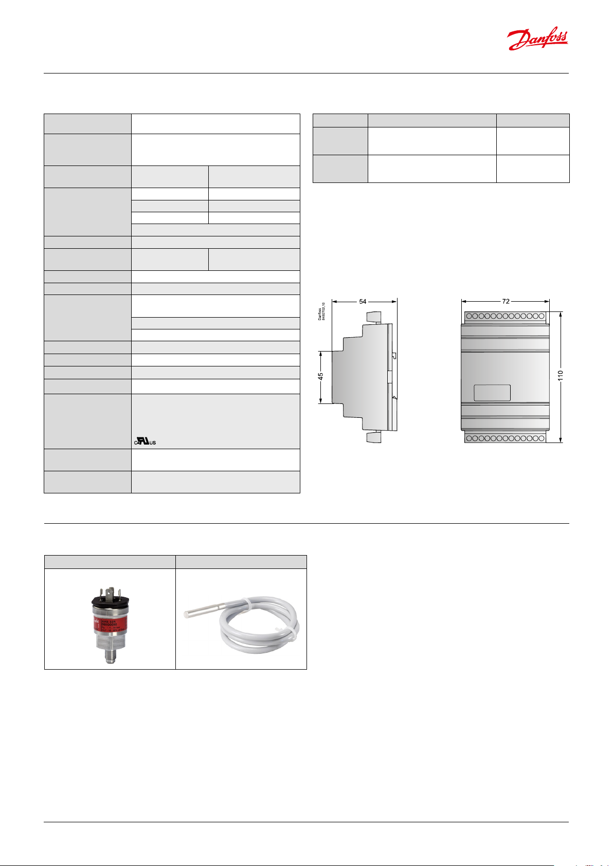
Data
Compatible valves ETS / CCM / CCMT 0 - 42 / CTR / ETS 6
Supply voltage
Power consumption
Input signal
*)Ri: mA: 400 ohm
V: 50 kohm
Sensor input 2 pcs. Pt 1000 ohm
Alarm relay 1 pcs. SPDT
Step motor output Pulsating 30 - 300 mA
Data communication Via CANbus
Environments
Enclosure IP 20
Weight 300 g
Montage DIN rail
Operation Via CANbus
Approvals
24 V AC / DC +/-15% 50/60 Hz, 10 VA
(the supply voltage is not galvanically
separated from the input and output signals)
Controller
ETS step motor
Current signal * 4-20 mA or 0-20 mA
Voltage signal * 0-10 V or 1-5 V
Pressure transmitter AKS 32R
Digital input from external contact function
0 to +55°C, during operations
-40 to +70°C, during transport
20 - 80% Rh, not condensed
No shock inuence/vibrations
EU Low Voltage Directive and EMC demands re.
CE-marking complied with.
LVD-tested acc. to EN 60730-1 and EN 60730-2-9
EMC-tested acc. to EN50081-1 and EN 50082-2
5 VA
1.3 VA
AC-1: 4 A (ohmic)
AC-15: 3 A (inductive)
Ordering
Type Function Code no.
EXD 316
EKA 183A Programming key 084B8582
superheat controller
(with terminals)
084B8042
Dimensions [mm]
Battery backup
Max. distance between
controller and valve
If battery backup is used, the requirements for
the battery are: 18-24 V DC.
30 m
Accessories
Pressure transducer Temperature sensor
AKS 32R, NSK AKS 21, AKS 11
© Danfoss | DCS (sw) | 2017.01
DKRCC.PD.RT0.A1.02 | 4
Page 5
Data sheet | Superheat controller type EXD 316
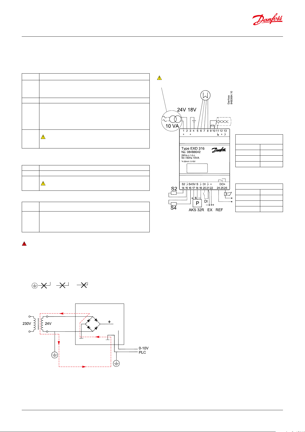
Connections
Necessary connections
Terminals:
1-2
3-4 Battery (the voltage will close the ETS valve if the
5-8 Supply to stepper motor
9-13
Supply voltage 24 V AC / DC
controller losses its supply voltage).
The battery voltage must not be connected from terminals 1
and 2.
Operation via data communication from a MCX
controller.
For manual for data communication, please see the
reference list on last page.
A dedicated transformer must be used.
R = 120 Ω
R
Data communication
20-21 Switch function for start/stop of regulation.
Note:
If a switch is not connected, terminals 20 and 21 must be short
circuited.
Application-dependent connections
Superheat control
14-15 Pt 1000 sensor at evaporator outlet (S2)
15-16 Pt 1000 sensor for measuring air temperature (S4)
17-19 Pressure transmitter type AKS 32R
Note:
The signal can not be shared with other controllers
Control of the valves opening degree with analog signal
21-22 Current signal or voltage signal from other regulation
(Ext. Ref.)
24-26 Alarm relay
There is connection between 24 and 26 in alarm
situations. When the controller is o there is connection
between 24 and 25.
Warning
Any external connection with grounding could create a ground
loop through a diode in the rectier bridge which could destroy
the power supply in EXD 316.
1,2 3,4 21,22
Class II
CANH
CANBUS
ETS / KVS / CCMT2 - CCMT42
/ CCM / CTR
White 5
Black 6
Red 7
Green 8
Connections EXD 316
GND
CANL
Connections EXD 316 /
ETS 6 / CCMT 0 - CCMT 1
Orange 5
Yellow 6
Red 7
Black 8
CANbus transmission lines should be terminated in both ends
with a resistor of approximately 120 Ohms.
Connection to earth will destroy the controller
AC / DC
© Danfoss | DCS (sw) | 2017.01
EXD 316
Danfoss
84N387.10
DKRCC.PD.RT0.A1.02 | 5
Page 6
OD
Data sheet | Superheat controller type EXD 316
Conguration
Independent superheat regulation
The superheat in the evaporator is controlled by one pressure
transmitter P and one temperature sensor S2. This can be done
setting o61 = 2.
Fitting the “S4” temperature sensor is optional, but the regulation
is improved by an “inner loop control” when the sensor is tted.
EXD 316
Function Parameter Value
Application Mode – superheat regulation o61 2
Selection of normal control mode 056 1
Valve driver (Via Analog Signal)
This is where the controller receives signals from another
controller, after which it controls the valve’s opening degree.
The signal can either be a current signal or a voltage signal.
Details can be found on the section “valve overview”.
I/V
EXD 316
Danfoss
84N394.10
I/V
EXD 316
Danfoss
84B2707.10
I/V
Danfoss
84N393.10
EXD 316
Function Parameter Value
Application Mode – superheat regulation o61 2
Selection of inner loop control mode 056 2
We recommend this inner loop control application mode setting, if
the superheating is to be regulated with precision. Here the S4 and
T0 temperature are part of an inner loop control.
The regulation algorithms require that a temperature sensor be
tted in the chilled medium.
The temperature sensor is connected to input "S4" and mounted
in the chilled medium after the evaporator. (Danfoss calls a sensor
S4 when it is mounted in the refrigerant after the evaporator).
External start/stop of regulation
The controller can be started and stopped externally via a contact
function connected to input terminals 20 and 21. Regulation is
stopped when the connection is interrupted. The function must
be used when the compressor is stopped. The controller then
closes the ETS valve so that the evaporator is not charged with
refrigerant.
Parameter Value Function
o61 1 Application Mode - control via analog signal
Relays
The relay for the alarm function is an alternating relay.
In the event of an alarm the relay will close to connect terminals 24
and 26. This can, for instance, be used for an alarm buzzer. When
there is no alarm or the controller is o, terminals 24 and 25 are
connected.
Parallel Evaporators with common suction line
Since the introduction of EEV, it has been observed the
phenomena the so-called Sleeping Evaporators phenomena have
been observed. This happens when the outlet of the evaporators
has a common suction line.
This is seen when using the Adaptive superheat Mode in some of
the controllers. What happens is that by controlling using the same
superheat reference in both controllers, evaporator No. 1 might be
controlling in the correct manner, but the EEV for evaporator No. 2
might be closed.
However, the measured superheat of controller No. 2 will be the
same as No. 1 because both S2 sensors will measure the same
temperature.
In other words, the open degree of the EEV integrates down to 0%
but, the measured superheat complies with the reference valve.
One solution is to use the Load-dened superheat Mode in the
controller because the measured superheat governs the opening
degree of the connected EEV.
EXD 316
Battery
For safety reasons the liquid ow to the evaporator must be cut
o if there is a power failure to the controller. As the ETS valve
is provided with a stepper motor, it will remain open in such a
situation. When mounting the battery backup, the valve will close
in the event of a power cut.
© Danfoss | DCS (sw) | 2017.01
EXD 316
Danfoss
84N391.10
DKRCC.PD.RT0.A1.02 | 6
Page 7
84N390.10
EXD 316
EXD 316
84N389.10
Data sheet | Superheat controller type EXD 316
Installation
The EXD 316 is normally mounted on a DIN rail, and the necessary
connections are shown in the diagram. If the sensor S4 is not
used to measure air temperature in connection with thermostat
function or as part of the controlling loop, then it is not necessary
to connect the S4 sensor. The 18-24 V battery input at terminals 15
and 16 is not required if battery back-up is not needed.
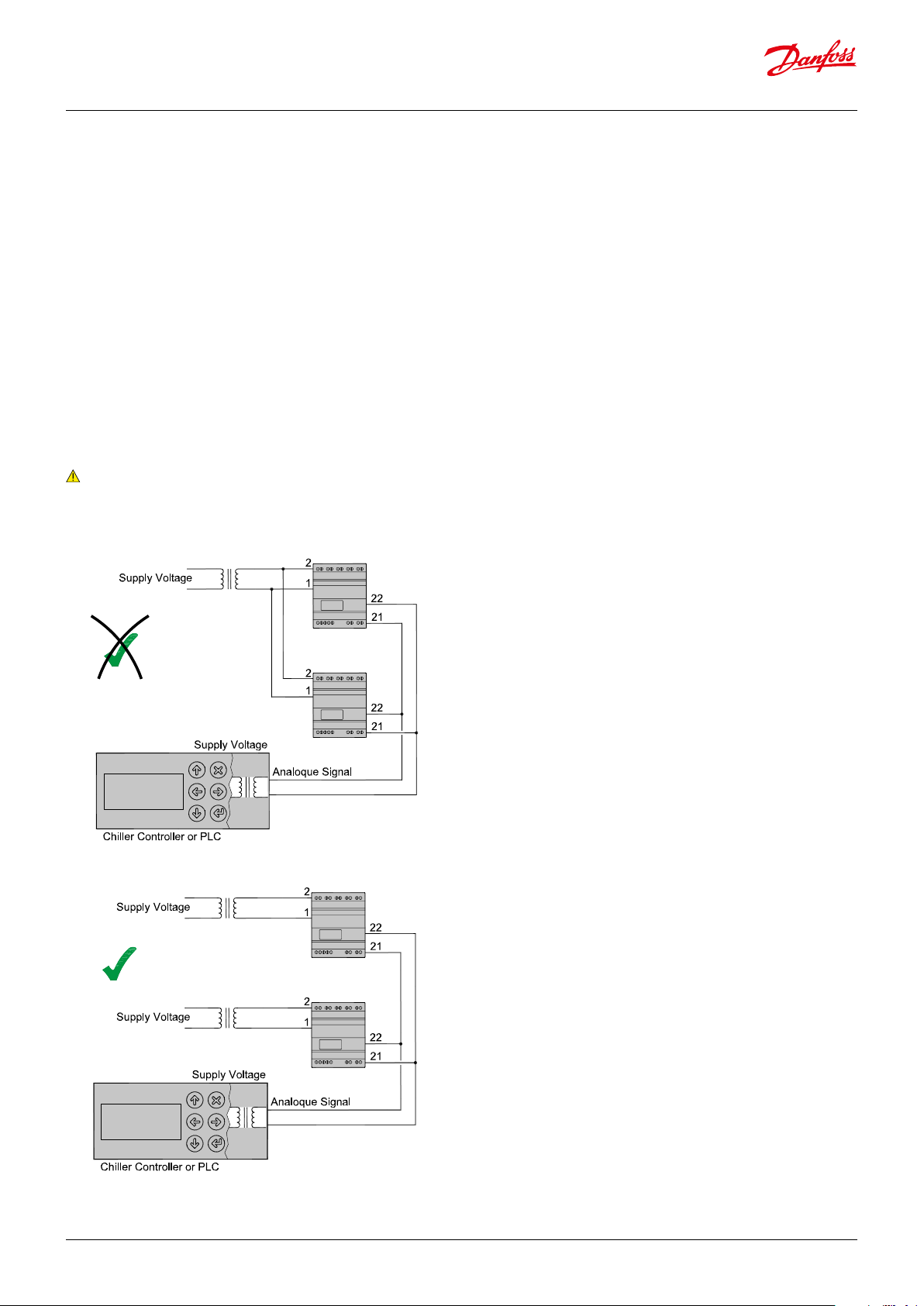
Power supply considerations
The terminals 1 and 2 for the voltage supply are not isolated
from the rest of the controller terminals. This means care should
be taken when connecting two or more controllers to the same
voltage supply. In the example below, the two controllers are
connected to the same voltage supply and on the input side,
terminals 21 (Analogue Input) are connected to each controller
and similarly terminals 22 (GND).
This way of connecting the controllers can cause damage and
should be avoided.
Note:
The same applies to other signal inputs e.g. terminals 2 and 4.
See warning page 5.
Danfoss
EXD 316
Stepper motor output
After installation the following checks can be made to the
connection between the EXD 316 controller and the stepper
motor of the valve.
With the power o, check that resistance between terminals 5 and
6 and terminals 7 and 8 is approximately:
ETS 6 / CCMT 0 : 46 Ohm
CCMT 1 : 31 Ohm
ETS / KVS / CCMT 2 - CCMT 8 / CCM / CTR : 53 Ohm
CCMT 16 - CCMT 42: 29 Ohm
Make slight allowances for cable resistance.
If resistance values dier from above, ensure that the cable is
properly connected to the actuator of the stepper motor valve.
1. With the power on and parameter o18 set to 1, measure the
phase current from terminal 5 (or 6) and terminal 7 (or 8 ) with
a true RMS multimeter when the valve is operating. The valve
can be driven from 0% to 100% and vice versa by changing
the valve opening percentage in parameter o45. The phase
current should be 100 mA rms (for ETS) when operating.
2. If this not the case and the cable connections are correct, then
the stepper motor driver in the EXD 316 might be damaged.
Remember to set o18 back to 0 after checks. If checks 1) and
2) are not correct, ensure that motor cable corrections are
correct and the cable length is less than 30 meters.
Output relay contact
The contact of the alarm relay will be made when there is an alarm.
Battery back-up
A battery back-up can be connected to terminals 3 (+) and 4 (-).
It is recommended to use 24 V DC 100 mAh UPS. The voltage
should be at least 18 V and this can be achieved by using two 9 V
100 mAh batteries in series, if temporary solution is to be used.
EXD 316
Data communication
EXD316 can be operated in connection with MCX controllers.
An MCX application software library and several complete
application software packages are available for managing the
valve controller.
Danfoss
In standalone applications EXD316 can be congured by running
an application software on MMIMYK that transfers the setup data.
For EXD conguration manual, please see the reference list on last
page.
© Danfoss | DCS (sw) | 2017.01
DKRCC.PD.RT0.A1.02 | 7
Page 8

EXD 316
Data sheet | Superheat controller type EXD 316
Installation sensors
S2 sensor positioning in the suction line
The position of the S2 sensor is crucial for an optimal control of the
liquid injection.
The main purpose is to measure temperature of the superheated
gas leaving the evaporator. In addition to this, the S2 sensor plays
an important role detecting fast changes of superheat. Suction
pressure is on the whole stable whereas the leaving gas condition
is dependent on the temporary mixture of gas, liquid refrigerant
and oil.
The sensor is also there to react quickly on liquid passing the
evaporator, to avoid damage to the compressor.
An S2 sensor placed two-thirds of the way up a riser after an oil
trap is where conditions are at their optimum, i.e. good mixture of
gas, oil and liquid droplets, provided this is not more than 0.5 m
from the evaporator.
If a horizontal pipe is the only option, the S2 sensor must be
placed at least half a meter away from the evaporator.
S1 (Po pressure) is less critical but must be close to the actual
suction pressure right after the evaporator.
If the measured value is 1-2 K lower than the actual value of Po
right after the evaporator, it may cause the evaporator to ood.
This is the case when the pressure transmitter is located in the
machine room away from the evaporator. If the measured value
is higher than the actual value of Po, the evaporator might be
starved of liquid.
Choice of S2 sensor type
Surface sensor S2 *
Suction pipe of copper or on thin (≤ 3mm) steel pipe.
Remember to put on heat conducting paste and insulate the
sensor.
Pocket sensor S2 **
Suction pipe of steel ≥ 3mm
*) Pt1000 Ω Type AKS 21 or AKS 10
**) Pt1000 Ω Type AKS 21W
AKS 21W
Heat compound
Danfoss
S2 sensor xing on the suction pipe:
84N395.10
When the S2 sensor is xed to the surface of the suction pipe, the
angle of the sensor position will depend on the diameter of the
pipe, as given in the following diagram:
© Danfoss | DCS (sw) | 2017.01
DKRCC.PD.RT0.A1.02 | 8
Page 9

Data sheet | Superheat controller type EXD 316
Start of controller
When the electric wires have been connected to the controller, the
following points have to be attended to before the regulation starts:
1. Switch o the external ON/OFF switch that starts and stops the
regulation.
2. Follow the menu survey in Appendix I, and set the various
parameters to the required values.
3. Switch on the external switch, and regulation will start.
4. Follow the actual superheat.
Settings and checks to be made before
start
Basic settings
Before using the controller, there are settings that have to be made
for each individual application. These are the refrigerant type, the
pressure transducer range and the total number of steps for the
ETS valve.
It is good practice and in some cases necessary to set the Main
Switch r12 to OFF when making these changes.
If terminal 20-21 has been used as a start/stop regulation, then the
interaction between internal and external start/stop function is, as
Refrigerant type
It is possible to choose from a list of 42 dierent refrigerants in the
controller.
Refrigerant setting
Before refrigeration can be started, the refrigerant must be dened.
You can select the following refrigerants:
1 = R12
2 = R22
3 = R134a
4 = R502
5 = R717
6 = R13
7 = R13b1
8 = R23
9 = R500
10 = R503
11 = R114
12 = R142b
13 = User-dened
14 = R32
15 = R227
16 = R401
17 = R507
18 = R402A
19 = R404A
20 = R407C
21 = R407A
22 = R407B
23 = R410A
24 = R170
25 = R290
26 = R600
27 = R600a
28 = R744
29 = R1270
30 = R417A
31 = R422A
32 = R413A
shown on the following table:
Internal
Start/stop
External
start/stop (DI)
O O => O No Yes
O On => O No Ye s
On O => O Yes No
On On => Yes Yes No
Regulation Sensor
monitoring
Conguration
settings
If the refrigerant is not found on the list, it is possible to enter
the Antione constants for the unlisted refrigerant using CANbus
communication or EKA 183A programming key and setting o30 to 13.
33 = R422D
34 = 427A
41 = R449A
42 = R452A
35 = R438A
36 = R513A
o30
37 = R407F
38 = R1234ze
39 = R1234yf
40 = R448A
( Warning: Wrong selection of refrigerant may cause damage to the compressor).
© Danfoss | DCS (sw) | 2017.01
DKRCC.PD.RT0.A1.02 | 9
Page 10

Data sheet | Superheat controller type EXD 316
Stepper motor valve type
It is important to select the right valve type as listed under Valve
denition. The valve selection will be as shown in table below.
In EXD 316, the set value at address n37 is always 10 times greater,
i.e. if n37 is set to 263 then the true value is 2630.
The number of steps and steps/sec can also be set in the controller
at addresses n37 and n38 respectively.
Valve overview EXD 316
n03 EKA 164A Danfoss valve type n37 n38
n03 EKA 183A Danfoss valve type n37 n38
0 ETS 12.5, ETS 25, KVS 15 262 300
0 ETS 12.5, ETS 25, KVS 15 262 300
1 ETS 50, CCM 10, CCM 20, CCM30 262 300
1 ETS 50, CCM 10, CCM 20, CCM30 262 300
2 ETS 100, CCM 40 353 300
2 ETS 100, CCM 40 353 300
3 ETS 250, KVS 42 381 300
3 ETS 250, KVS 42 381 300
4 ETS 400 381 300
4 ETS 400 381 300
5 User dened - -
5 User dened - -
6 UKV/SKV/VKV/PKV 24 16
6 UKV/SKV/VKV/PKV 24 16
7 ETS 6 24 16
7 ETS 6 24 16
8 CCMT 2, CCMT 4, CCMT 8 110 220
8 CCMT 2, CCMT 4, CCMT 8 110 220
9 CCMT 16 80 200
9 CCMT 16 80 200
10 CCMT 24 140 200
10 CCMT 24 140 200
11 CCMT 30 230 200
11 CCMT 30 230 200
12 CCMT 42 220 200
12 CCMT 42 220 200
13 CTR 660 75
13 CTR 660 75
14 CCMT 0 24 16
14 CCMT 0 24 16
15 CCMT 1 24 16
15 CCMT 1 24 16
Pressure transmitter
Pressure transmitter
The range of the pressure transmitter can be set by entering the
The range of the pressure transmitter can be set by entering the
transmitter’s minimum value at address o20 and maximum value
transmitter’s minimum value at address o20 and maximum value
at address o21. The pressure sensor input is set up by default to
at address o21. The pressure sensor input is set up by default to
accept an AKS 32R pressure transducer. If another sensor is to be
accept an AKS 32R pressure transducer. If another sensor is to be
used, it is important to note that it needs to be a 5 V ratiometric
used, it is important to note that it needs to be a 5 V ratiometric
type (10% - 90% of supply voltage).
type (10% - 90% of supply voltage).
Working range for pressure transmitter
Working range for pressure transmitter
Depending on the application a pressure transmitter with a given working range is used.
Depending on the application a pressure transmitter with a given working range is used.
For the range of (-1 to 12 bar), the min. value is set to -1 bar o20 MinTransPres.
For the range of (-1 to 12 bar), the min. value is set to -1 bar o20 MinTransPres.
For the range of (-1 to 12 bar), the max. value is set to 12 bar o21 MaxTransPres.
For the range of (-1 to 12 bar), the max. value is set to 12 bar o21 MaxTransPres.
The default range for the typical pressure transducer is 0 to 16 bar.
The default range for the typical pressure transducer is 0 to 16 bar.
This can be changed by setting the minimum transducer pressure,
This can be changed by setting the minimum transducer pressure,
"o20 MinTransPres", and the maximum transducer pressure, "o21
"o20 MinTransPres", and the maximum transducer pressure, "o21
MaxTransPres", to the new values.
MaxTransPres", to the new values.
© Danfoss | DCS (sw) | 2017.01
DKRCC.PD.RT0.A1.02 | 10
Page 11

MOP
Data sheet | Superheat controller type EXD 316
Operation
Superheat function
You may choose between two kinds of superheat regulation,
either:
• Minimum stable superheat (MSS)
• Load-dened superheat
The regulation modes for controlling superheat
There are two dierent ways of controlling superheat, i.e.
controlling according to the minimum stable superheat (MSS) and
Load Dened superheat.
The parameter SH mode selects the controlling form where it can
be set to MSS when set to 1, or Load Dened superheat when set
to 2.
Minimum stable superheat (MSS)
The superheat control algorithm will attempt to regulate the
superheat down to the lowest stable value between the minimum
superheat setting, "Min SH" and the maximum superheat setting,
"Max SH".
The reference follows a dened curve. This curve is dened by
three values: the closing value, the min. value and the max. value.
These three values must be selected in such a way that the curve
is situated between the MSS curve and the curve for average
temperature dierence ∆Tm (temperature dierence between
media temperature and evaporating temperature.
Setting example = n22=4, n10=6 and n09=10 K).
Function Parameter Value
Superheat control mode -2
= Load dene
n21 2
Min Superheat Reference n10 1 - 100 K
Max Superheat Reference n09 1 - 100 K
Value of min. SH ref for loads
under 10%
n22
Must be between
Min and Max SH
The superheat reference SH ref is adaptive and adjusted.
When using this form of control, there are three settings that have
major aect on this mode of control.
Max SH – The maximum limit of SH ref.
Min SH – The minimum limit of SH ref. Care should be taken not
to set this value too low in order to avoid ooding back into the
compressor.
Stability – This factor determines how much instability can be
accepted. Small values will cause the SH ref to increase if the
slightest instability in SH is detected. Higher values will accept a
higher degree of instability.
Function Parameter Value
Superheat control -MSS n21 1
Min Superheat Reference n10 1 - 100 K
Max Superheat Reference n09 1 - 100 K
Load dene application
SH ref follows a dened curve as shown below. This curve is
dened by three values: SH close SH max and SH min.
Using the MOP
In order to reduce the current to the compressor it is possible to
control the maximum operating pressure of the evaporator.
Evaporator pressure exceeds the "MOP" limit, the valve opening
degree is controlled by the MOP function which will keep the
pressure below the "MOP" limit. This function takes precedence
over the superheat control, so during MOP control the superheat is
not controlled.
The MOP function (address n11) is active when it is set to values
less than the maximum range of the pressure transmitter. Setting
it above the maximum range of the pressure transmitter or at 200
Bar will deactivate the MOP.. The pressure value is converted to
the corresponding temperature value and when the MOP is active,
the controller will prevent the evaporating temperature T1 from
exceeding this value.
If Maximum Operating suction Pressure MOP parameter n11 is
reset from factory setting 20 to 1 bar (gauge) From the MOP i.e 1
bar point the OD increases slower and slower until the pressure
reaches MOP + 0.5 i.e 1.5 bar. Subsequently the OD decreases
rapidly as the pressure increases.
At this pressure the OD
no longer increases.
Beyond it the OD
decreases.
+ 0.5
MOP
At this pressure the OD
increases slower and
slower.
Pressure Pe
This form of regulation is similar to the thermostatic valve where
the spring force can be adjusted to keep the SH (superheat) in the
stable region to the right of the curve.
The advantage over the thermostatic valve is that there are three
settings to dene the operating curve.
© Danfoss | DCS (sw) | 2017.01
OD
Function Parameter Value
Maximum operating pressure
MOP
n11 0-200 bar
DKRCC.PD.RT0.A1.02 | 11
Page 12

Data sheet | Superheat controller type EXD 316
Types of regulation
As a general rule, do not use mode 2 (Load dene application)
if the eect is not evaluated by e.g. an OEM chiller
manufacturer in a laboratory.
An incorrect setting will only make regulation poorer than the
factory setting of mode 1.
Instability caused by too much Proportional Gain can be corrected
by reducing to the value of the Kp factor.
This should be done by gradually reducing and observing the
results before making further reductions.
Single Loop (address o56 Reg.type = 1)
The EXD 316 has the traditional PI controlling function with the Kp
factor for Proportional Gain and Tn for Integration Time in seconds.
This is also known as the Single loop control with only one PI
block, as shown in the diagram below.
Double Loop (address o56 Reg.type = 2)
The controller can regulate the superheat using a double loop
system. The so-called outer loop is really the same as in the single
loop system except that the output of PI block is the reference for
the inner loop.
The inner loop also has a PI block where the Proportional Gain
factor is KpT0 and the Integration Time is TnT0.
The feedback of the inner loop is the temperature dierence
between media temperature S4 and S1. This value represents the
load on the evaporator and large values will tend to increase the
opening degree OD% of the valve.
When to use Single or Double Loop
In most applications and especially air coolers, the single loop is
the best option due to its simplicity and being easier to tune.
In water chillers where the S4 sensor is located at the leaving water
outlet, the double loop gives some advantage in terms of being
less susceptible to compressor or fan step changes. In addition, it
opens the valve quicker during startup. However, the double loop
is less advantageous on air coolers because of the slower response
to the media temperature changes.
If the superheat response is slow to change, it can be increased by
reducing the value of the Integration Time Tn.
When tuning the superheat stability, it is good practice to have a
xed superheat reference by making SH max the same as SH min.
The tuning of the double loop is more complicated than the single
loop and it is advisable not to change too many parameters at
the same time. The starting point should be to use the following
settings.
Function Parameter Value
Kp factor n04 0.7
Tn sec n05 120
KpT0 n20 3
TnT0 sec n44 30
If the superheat is unstable, the KpT0 parameter should be slightly
reduced. The value parameter Kp factor is not large so little is
gained by reducing this parameter.
For details refer to the "Finding the optimum setting” section.
Note:
The S4 sensor has to be connected when Reg. type = 2, otherwise
an alarm sounds.
Note:
After o56 is changed, the controller must be switched o and
powered up again.
Recommended control loop type and settings for some
applicatiions
From the experience of using single loop and double regulation,
the following recommendations are given. These are only
recommendations and the nal choice is made by the end user.
Application Reg. type
address
n56
Air cooler
Water chiller2(Double
1
(Single loop)
loop)
Kp
factor
address
n04
3.0 120 0.4 -
0.7 120 2.0 30
Tn sec KpT0 TnT0 sec
address
n05
address
n20
address
n44
© Danfoss | DCS (sw) | 2017.01
DKRCC.PD.RT0.A1.02 | 12
Page 13

Data sheet | Superheat controller type EXD 316
Manually operating the valve
There are two modes for operating the valve manually, and these
are described in the following sections.
Operating the valve manually from the CANbus
The opening degree of the ETS can be operated manually by
setting parameter o18 to 1 and then setting parameter o45 to the
required opening degree between 0% and 100%. Relay outputs
can also be checked using parameter o18.
Manual control of outputs
For service purposes the valve output and alarm relay outputs can be forced.
OFF: No override
1: Manual control via o45 is enabled
2: The alarm relay releases so that there is a connection between 24 and 25 (= alarm)
3: The alarm relay picks up so that there is a connection between 25 and 26 (= no alarm)
Manual control of the valve’s opening degree 045 0 - 100% valve OD
Operating the valve manually using an external analog signal
The opening degree of the stepper motor valve can be operated
manually with 0 - 20 mA or 4 - 20 mA or 0 - 10 V or 1 - 5 V external
analog signal connected to terminals 21 (-) and 22 (+) of the
controller.
018 Manual ctrl
Controlling a valve with an analogue signal 061 Application mode 061=1
Input signal for external control of the valve's opening degree
Only used if o61 is set to 1.
Denition of the signal's range:
0: No signal
1: 0 - 20 mA
2: 4 - 20 mA
3: 0 - 10 V
4: 1 - 5 V
(At the lower value the valve will be closed. At the upper value the value will be fully open.
There is a linear relationship between the signal and the opening degree. The height of the
valve is not taken into account.)
o10
AI type
© Danfoss | DCS (sw) | 2017.01
DKRCC.PD.RT0.A1.02 | 13
Page 14

Data sheet | Superheat controller type EXD 316
Finding the optimum settings
Details on the controller algorithm and settings
Kp factor (n04) and Kp min (n19)
The Proportional Gain is dependent on the value of the measured
superheat SH relative to Reference superheat SH ref. The
Proportional Gain has the following values relative to superheat SH:
If SH is more than 2.5K greater than SH ref, then Gain equals Kp
factor.
If SH is within the range -0.5 and 2.5K from SH ref, then Gain equals
Kp factor times Kp min.
The reason for this variable Gain is to provide stable superheat for
values near the superheat reference.
Note:
The value of Gain does not change suddenly but gradually when
SH gets close to SH ref.
Proportional Gain
Kp factor
Danfoss
84N375.11
Problems with startup
Sometimes in one-to-one applications, the valve does not open
suciently on startup, and troublesome low pressure trips may
occur. This problem is typical when using the single loop control
where only the SH controls the opening of the valve.
The force opening of valve function has been implemented in
the EXD 316 controller. After startup, this function will provide a
constant, set minimum opening degree during a set time period,
regardless of the superheat value. The setting parameters are
called Start OD% (n17) and StartUp time (n15).
Please observe that the Start OD% is a minimum value after
startup and if the measured superheat (u21) produces a value
greater than Start OD% then the value will be valve opening
degree (u24) – see the diagram.
OD%
Valve OD%
Start OD%
Reg.OD%
Danfoss
84N378.11
Kp factor multiplied Kp min.
-0.5
2.5
SH ref
SH
Initial "Kick start" startup
In general the valve opening degree is controlled by the measured
value of the superheat SH. This means that during certain
situations during startup, the valve will be slow to open due to
the built-up of superheat from a small value. To prevent this from
happening, the valve is given an initial opening degree dependent
on the Kp factor, the measured superheat SH and SH close, as
given in the following relationship:
Initial OD% = kp factor*(SH – SH close)
This procedure is not to be confused with the force opening of the
valve given in the “Problems with startup” section.
OD%
Kp factor* (SH - SH Close)
When Kp factor = 3, SH = 12, Close = 2
Initial OD % = 30%
Start
Time
Danfoss
84N376.11
Forced OD%
Normal Reg.
Start Up time*
Start
Time from start
If the superheat uctuates
When the refrigerating system has been made to work steadily,
the controller’s factory-set control parameters should in most
cases provide a stable and relatively fast regulating system.
If the system, however, uctuates this may be due to the fact that
superheat parameters that are too low have been selected. Before
starting any adjustment of the factory settings check the S2 sensor
location – see section “Installation sensors”.
If adaptive superheat has been selected (n21 = 1):
Adjust: n09, n10 and n18.
If load-dened superheat MSS has been selected (n21 = 2):
Adjust: n09, n10 and n22.
Alternatively it may be due to the fact that the set regulation
parameters are not optimal.
If the time of oscillation is longer than the integration time:
(Tp > Tn (Tn is e.g. 240 seconds))
1. Increase Tn to 1.2 times T
2. Wait until the system is in balance again
3. If there is still oscillation, reduce Kp by e.g. 20%
4. Wait until the system is in balance
5. If it continues to oscillate, repeat 3 and 4
If the time of oscillation is shorter than the integration time:
(Tp < Tn (Tn is e.g. 240 seconds))
1. Reduce Kp by e.g. 20% of the scale reading
2. Wait until the system is in balance
3. If it continues to oscillate, repeat 1 and 2.
p
© Danfoss | DCS (sw) | 2017.01
DKRCC.PD.RT0.A1.02 | 14
Page 15

Data sheet | Superheat controller type EXD 316
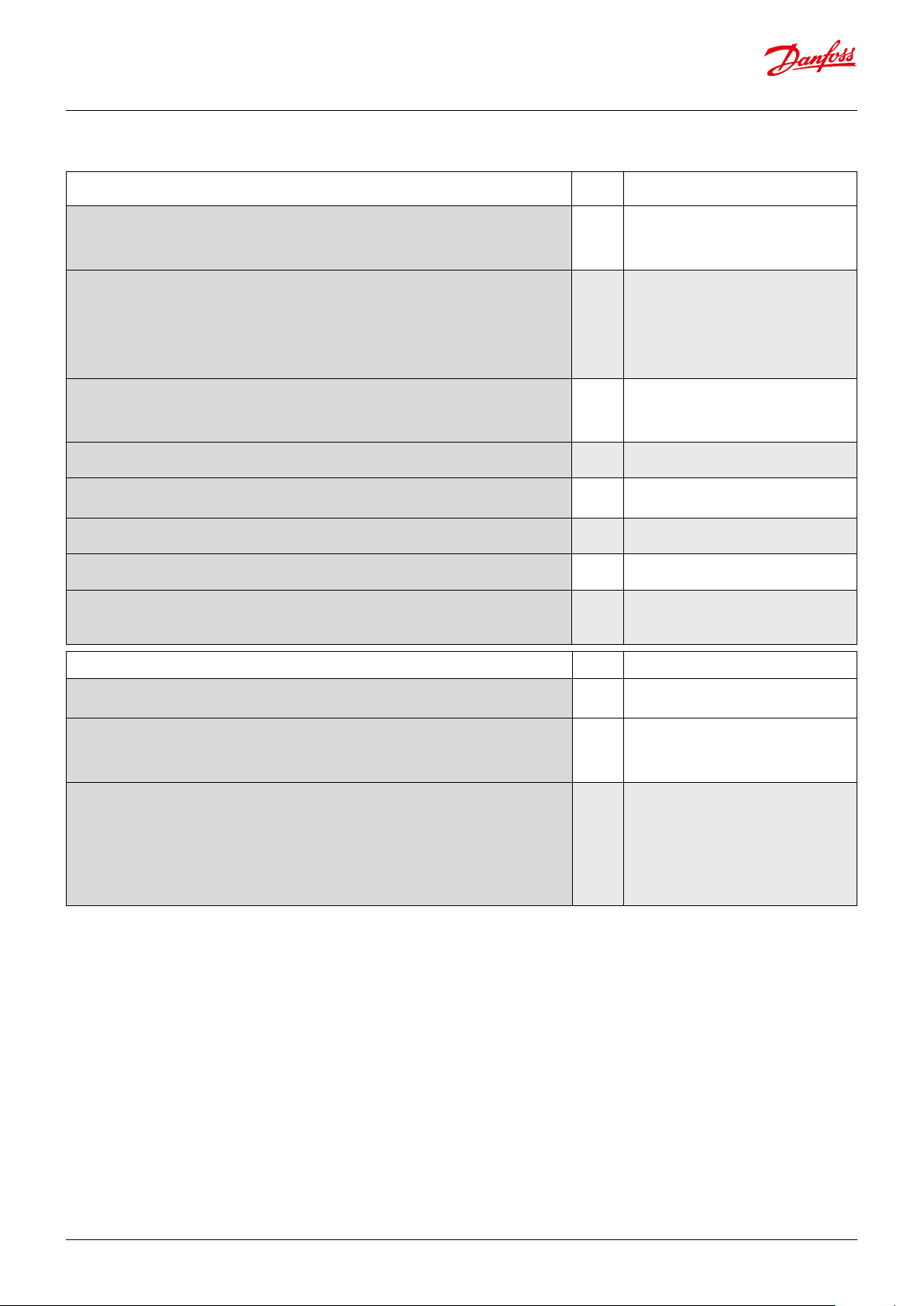
Troubleshooting
Symptom Possible Cause Remedy
Pressure drop across the evaporator too high
Lack of subcooling ahead of expansion valve
Evaporator superheat too high
Suction pressure too low
Pressure drop across the expansion valve less than valve is
sized for
Expansion valve too small
Expansion valve block with foreign material Remove valve and examine the orice.
Evaporator wholly or partly iced up De-ice evaporator
Superheat of expansion valve too low Increase the values of SH close and SH min.
Liquid hammer
in compressor
Superheat reference set too low Increase the value of SH min
The S2 sensor not in good contact with the suction line
Alarms
Check refrigerant ahead of expansion valve.
If the valve is placed much higher than condenser outlet,
check pressure dierence.
1. Check superheat performance, the settings
SH min and SH max.
2. Check valve capacity.
3. Check that the maximum number of steps of
valve is same as parameter n37.
Check pressure drop across expansion valve. Replace with
larger valve.
Check refrigeration system capacity and compare with
expansion valve capacity. Replace with larger valve if
necessary.
Ensure that S2 sensor is secured on suction line. Insulate
sensor.
Symptom Possible Cause Fault Message Remedy
E*1 Fault in controller
E*2 S2 Sensor error
Error message
The controller can give the
following messages
Alarm message
Status codes
E*3 S4 Sensor error
E*4
E*5 The input signal on terminals 21-22 is outside the range.
E*6 No refrigerant has been selected
E*7 Check the supply voltage to the stepper motor.
E*8 Battery alarm (no voltage or too low voltage)
S5 MOP
S10 Refrigeration stopped r12=o
non Regulation, no fault
The input signal on terminals 17-19 is below
minumum limit (P0 signal)
© Danfoss | DCS (sw) | 2017.01
DKRCC.PD.RT0.A1.02 | 15
Page 16

Data sheet | Superheat controller type EXD 316
Appendix I
Menu survey for EXD 316
262
Application
choice
menu = o61
Function
The menus from either column 1 or column 2 are shown 1 2
Reading
Actual level of superheat unit. - K Opening degree unit. - % -
Reference
Units (0 = °C +bar / 1 = °F + psig) r05 0 1 0
Correction of signal from S2 r09 -10.0 K 10.0 K 0.0
Correction of signal from S4 r10 -10.0 K 10.0 K 0.0
Start/stop of refrigeration r12 O/0 On/1 O/0
Alarm
Battery monitoring A34 O/0 On/1 O/0
Regulating parameters
Valve denition:
0 = ETS 12.5, ETS 25, KVS 15
1 = ETS 50, CCM 10 – CCM 30
2 = ETS 100, CCM 40
3 = ETS 250, KVS 42
4 = ETS 400
5 = user-dened
P: Amplication factor Kp
o56 = 1; n04 = 2.0
o56 = 2; n04 = 0.7
( Warning: Changes to n04 are lost when changing o56)
I: Integration time T
D: Dierentiation time Td (0 = o ) n06 0 s 90 s 0
Max. value of superheat reference n09 1 K 100 K 10
Min. value of superheat reference n10 1 K 100 K 6
MOP (max = o) n11 0.0 bar 200 bar 20
Signal reliability during startup. Safety time period.
Should only be changed by trained sta
Signal reliability during startup – opening degree’s start value. Should only be changed by trained sta. n17 0% 100% 0
Stability factor for superheat control.
Changes should only be made by trained sta
Damping of amplication around reference value
Changes should only be made by trained sta
Amplication factor for superheat
Changes should only be made by trained sta
o56 = 1; n20 = 0.4
o56 = 2; n20 = 3.0
( Warning: Changes to n20 are lost when changing o56)
Denition of superheat control mode
1 = MSS,
2 = LOADAP
Value of min. superheat reference for loads under 10% n22 1 K 15 K 4
Max. opening degree
Changes should only be made by trained sta
Number of steps from 0 - 100% opening degree (only if n03 = 5 (User-dened))
Number of steps per second n38 5 stp/s 300 stp/s 300
Start backlash (extra closing steps at 0% opening (in % of n37)) n39 0% 100% 10
Integration time for inner loop (TnT0) n44 10 s 120 s 30
Compensation for spindle play n40 0 stp 100 stp 23 stp
6 = UKV/SKV/VKV/PKV
7 = ETS 6
8 = CCMT 2 – CCMT 8
9 = CCMT 16
10 = CCMT 24
11 = CCMT 30
12 = CCMT 42
13 = CTR
14 = CCMT 0
15 = CCMT 1
Para-
meter
n03 0 15 1
n04 0.5 20 2.0/0.7
n05 30 s 600 s 120
n15 0 sec. 90 sec. 0
n18 0 10 5
n19 0.0 1.0 0.3
n20 0.0 10.0 0.4/3.0
n21 1 2 1
n32 0 % 100 % 100
n37
Min. Max.
10
(100 stp)
Factory
setting
999
(9990
stp)
© Danfoss | DCS (sw) | 2017.01
DKRCC.PD.RT0.A1.02 | 16
Page 17

Data sheet | Superheat controller type EXD 316
Menu survey for EXD 316 continued
Function
The menus from either column 1 or column 2 are shown
Parameter
Min. Max.
Miscellaneous
Controller’s address o03 0 240 240
If the valve’s opening degree should be controlled with an external signal, the signal is dened as:
0: no
signal
1: 0 - 20 mA 2: 4 - 20 mA 3: 0 - 10 V 4: 1 - 5 V
o10 0 4 0
Manual control of outputs:
OFF: no manual control
1: Manual control with "o45" enabled
o18 o/0 3 O /0
2: Simulate Alarm o : connection between 24 and 25
3: Simulate Alarm on : connection between 24 and 26
Working range for pressure transmitter – min. value o20 -1 bar 0 bar -1.0
Working range for pressure transmitter – max. value o21 1 bar
Refrigerant setting
1 = R12
2 = R22
3 = R134a
4 = R502
5 = R717
6 = R13
7 = R13b1
8 = R23
9 = R500
10 = R503
11 = R114
12 = R142b
13 = User def.
14 = R32
15 = R227
16 = R401A
17 = R507
18 = R402A
19 = R404A
20 = R407C
21 = R407A
22 = R407B
23 = R410A
24 = R170
25 = R290
26 = R600
27 = R600a
28 = R744
29 = R1270
30 = R417A
31 = R422A
32 = R413A
33 = R422D
34 = 427A
35 = R438A
36 = R513A
37 = R407F
38 = R1234ze
39 = R1234yf
40 = R448A
41 = R449A
42 = R452A
o30 0 42 0
200
bar
Factory
setting
12.0
Application
choice
menu = o61
1 2
Manual control of the valve’s opening degree. The function can only be operated if o18 has been set
to "1".
o45 0 % 100 % 0
This function is only for manual operation. It must not be used for as a regulation function.
Selection of control mode:
1= Normal
o56 1 2 1
2 = With inner loop (S media temperature less T0)
Application mode. Menus blanked out so only the shaded menus are seen. See the two columns to
the right.
1: Controlling a valve with an analogue signal
o61 1 2 2 1 2
2: Superheat regulation
Holding current h22 0 % 100 % 20 %
High pressure alarm o99 0 1 0
Overdrive
Open hysteresis is the minimum requested opening degree required before the valve will open. This value cannot
be lower than the Close hysteresis.
Close hysteresis: if the requested opening degree is below this value, the valve will close to 0%. This value cannot
be set higher than the Open hysteresis.
Overdrive enable level. The opening degree needs to be above this value, before the overdrive will become enabled. When the overdrive is enabled the valve will overdrive once it is closed to 0%
Overdrive protection time. The valve will not overdrive until this time has elapsed after the last overdrive. This
prevents too frequent overdrives. The default is 0 meaning that it is o and doesn’t limit overdrives.
Forced overdrive time. The valve is forced to close and overdrive after this time has elapsed. The valve will then
open again to the desired opening degree. The default is 0 meaning it is o and doesn’t force close.
P67 0% 100% 1%
P68 0% 100% 1%
P69 0% 100% 10%
P70 0 hours
P71 0 hours
999
hours
999
hours
0
0
Service
Analog input (21 - 22) u06 mA (V)
Read status of input DI (20 - 21) u10 on/o
Temperature at S2 sensor u20 °C
Superheat u21 K
Superheat reference u22 K
Read valve’s opening degree u24 %
Read evaporating pressure
u25 bar
Read evaporating temperature u26 °C
Temperature at S4 sensor
Conguration settings (n03, n37, n38, n39, n40, o03, o30, o56 and o61) available only when regulation is stopped (r12=o).
Factory settings are indicated for standard unit (see code number, page 4). Other code number have customised settings.
u27 °C
© Danfoss | DCS (sw) | 2017.01
DKRCC.PD.RT0.A1.02 | 17
Page 18

Data sheet | Superheat controller type EXD 316
Survey of functions
Function Para-
Reference
Unit
Here you select whether the controller is to indicate the temperature values in °C or in
°F and pressure values in bar or psig.
If indication in °F is selected, other temperature settings will also switch to Fahrenheit,
either as absolute values or as delta.
The combination of temperature unit and pressure unit is depicted to the right.
Correction of signal from S2
(Compensation possibility through long sensor cable).
Correction of signal from S4
(Compensation possibility through long sensor cable).
Start/stop of refrigeration
With this setting, refrigeration can be started and stopped. Start/stop of refrigeration
can also be accomplished with the external switch function. See also appendix 1.
Alarm
Battery alarm
Here it is dened whether the controller is to monitor the voltage from the battery
backup. If there is low voltage, or no voltage, an alarm will be given
Control parameters Injection control
Valve denition for EXD 316.
0 = ETS 12½, ETS 25, KVS 15
1 = ETS 50, CCM 10 – CCM 30
2 = ETS 100, CCM 40
3 = ETS 250, KVS 42
4 = ETS 400
5 = user-dened
6 = UKV/SKV/VKV/PKV
7 = ETS 6
8 = CCMT 2 – CCMT 8
9 = CCMT 16
10 = CCMT 24
11 = CCMT 30
12= CCMT 42
13= CTR
14= CCMT 0
15= CCMT 1
meter
Parameter by operation via
data communication
Units (Menu = Misc.)
r05
0: °C + bar
1: °F + psig
r09 Adjust S2
r10 Adjust S4
r12 Main Switch
Alarm setting
A34 Batt. alarm
n03 Valve type
P: Amplication factor Kp
If the Kp value is reduced the regulation becomes slower.
I: Integration time Tn
If the Tn value is increased the regulation becomes slower.
D: Dierentiation time Td
The D-setting can be cancelled by setting the value to min. (0).
Max. value for the superheat reference
Min. value for the superheat reference
Warning:
Due to the risk of liquid ow, the setting should not be lower than approx. 2-4 K.
MOP Note:
If no MOP function is required, select pos. O. (A value of 200 corresponds to O)
Startup time for safety signal
If the controller does not obtain a reliable signal within this period of time the controller will try to establish a stable signal in other ways. (A value that is too high may
result in a ooded evaporator).
The value should only be changed by specially-trained sta .
Signal safety during startup
The control function uses the value as a start value for the valve’s opening degree at
each thermostat cut-in. By adaptive control the controller continuously calculates a
new value.
The value should only be changed by specially-trained sta.
Stability factor for regulation of superheat
With a higher value, the control function will allow a greater uctuation of the superheat before the reference is changed. The value should only be changed by speciallytrained sta.
n04 Kp factor
n05 Tn sec.
n06 Td sec.
n09 Max SH
n10 Min SH
n11 MOP (bar)
n15 StartUp time
n17 Start OD%
n18 Stability
© Danfoss | DCS (sw) | 2017.01
DKRCC.PD.RT0.A1.02 | 18
Page 19
Data sheet | Superheat controller type EXD 316
Survey and function (continued)
Function Para-
Damping of amplication near reference value
This setting damps the normal amplication Kp, but only just around the reference
value. A setting of 0.5 will reduce the KP value by half.
The value should only be changed by specially-trained sta.
Amplication factor for the superheat
This setting determines the valve’s opening degree as a function of the change in
evaporating pressure. An increase of the evaporating pressure will result in a reduced
opening degree. When there is a drop-out on the low-pressure thermostat during
startup, the value must be raised slightly. If there is pendling during start-up, the
value must be reduced slightly.
The value should only be changed by specially-trained sta.
Denition of superheat regulation (Ref. section "Operation")
1: Lowest permissible superheat (MSS). Adaptive regulation.
2: Load-dened superheat. The reference is established based on the line formed by
the three points: n09, n10 and n22.
Value of min. superheat reference for loads under 10%
(The value must be smaller than "n10").
Max. opening degree
The valve’s opening degree can be limited. The value is set in %.
Number of steps from 0% to 100% open (User-dened valve, n03 =5)
(Automatic setting when valve is selected in n03).
Spindle stroke speed (number of steps per second)
(Automatic setting when valve is selected in n03).
Integration time for the inner loop gain
Used only when o56 = 2
The value should only be changed by specially-trained sta.
meter
n19 Kp Min
n20 Kp T0
n21 SH mode
n22 SH Close
n32 ETS OD% Max
n37 Max. steps (100 to 9990 step)
n38 Steps/sec (5 to 300 step/sec)
n44 TnT0 sec
Parameter by operation via
data communication
Miscellaneous
Address/data communication
The controller must always have an address. The factory address is 20.
Application mode
1: The controller receives signals from another controller and must control the valve’s
opening degree.
2: Superheat regulation.
Input signal for external control of the valve‘s opening degree
Only used if o61 is set to 1.
Denition of the signal's range.
0: No signal
1: 0-20 mA / 2: 4-20 mA / 3: 0-10 V / 4: 1-5 V
(At the lower value the valve will be closed. At the upper value the value will be fully
open. There is a linear relationship between the signal and the opening degree. The
height of the valve is not taken into account.)
o61 Appl. mode
o10 AI type
© Danfoss | DCS (sw) | 2017.01
DKRCC.PD.RT0.A1.02 | 19
Page 20

Data sheet | Superheat controller type EXD 316
Survey and function (continued)
Function Para-
meter
Manual control of outputs
For service purposes the ETS-output and alarm relay outputs can be forced
However, only when regulation has been stopped.
OFF: No override
1: Manual control via o45 is enabled
2: The alarm relay releases so that there is a connection between 24 and 25 (= alarm)
3: The alarm relay picks up so that there is a connection between 25 and 26 (= no alarm)
Manual control of the ETS valve
The valve‘s opening degree can be set manually.
However, it does require "o18" to be set to "1", "2" or "3".
This function must only be used for manual operation. It must not be used for external
control.
Working range for pressure transmitter
Depending on the application, a pressure transmitter with a given working range is
used.
For the range of (-1 to 12 bar), the min. value is set to -1 bar.
For the range of (-1 to 12 bar), the max. value is set to 12 bar. o21 MaxTransPres.
Selection of control algorithm
Depending on the application, control can be carried out based on dierent parameters.
The two possibilities are shown in section "Type of regulation".
1=normal control (single loop)
2=with inner loop regulation and S4 temperature less T0 (double loop)
Note:
* After o56 is changed, the controller must be switched o and powered up again.
Refrigerant setting
Before refrigeration can be started, the refrigerant must be dened. You can select
the following refrigerants:
1 = R12
2 = R22
3 = R134a
4 = R502
5 = R717
6 = R13
7 = R13b1
8 = R23
9 = R500
10 = R503
11 = R114
12 = R142b
13 = User def.
14 = R32
15 = R227
16 = R401A
17 = R507
18 = R402A
19 = R404A
20 = R407C
21 = R407A
22 = R407B
23 = R410A
24 = R170
25 = R290
26 = R600
27 = R600a
28 = R744
29 = R1270
30 = R417A
31 = R422A
32 = R413A
33 = R422D
34 = 427A
35 = R438A
36 = R513A
37 = R407F
38 = R1234ze
39 = R1234yf
40 = R448A
41 = R449A
42 = R452A
( Warning: Incorrect selection of refrigerant may cause damage to the compressor).
Parameter by operation via
data communication
o18 Manual ctrl
o45 Manual ETS OD%
o20 MinTransPres.
o56 Reg. type *
o30 Refrigerant
Service Service
A number of controller values can be printed for use in a service situation
Read value of external current signal/voltage signal (Ext.Ref.) u06 Analogue input
Read status of input DI (start/stop input) u10 DI
Read the temperature at the S2 sensor u20 S2 temp.
Read superheat u21 SH
Read the control’s actual superheat reference u22 SH ref.
Read the valve’s opening degree u24 OD%
Read evaporating pressure u25 Evap. pres. P
Read evaporating temperature u26 Evap.Press.T
e
e
Read the temperature at the S4 sensor u27 S4 temp.
-- DO1 Alarm
Read status of alarm relay
© Danfoss | DCS (sw) | 2017.01
DKRCC.PD.RT0.A1.02 | 20
Page 21

Data sheet | Superheat controller type EXD 316
Appendix II
EXD 316 – Parameter identication (CANbus)
Explanations:
Parameter – The parameter name and abbreviation
Parameter CANbus adress
r05 Temp.unit 0x5100,0x00
r09 Adjust S2 0x5100,0x01
r10 Adjust S3 0x5100,0x02
r12 Main switch 0x5100,0x03
A34 Battery low 0x5100,0x37
n03 Valve type 0x5100,0x20
n04 Kp factor 0x5100,0x21
n05 Tn seconds 0x5100,0x22
n06 Td seconds 0x5100,0x23
n09 Max SH 0x5100,0x38
n10 Min SH 0x5100,0x24
n11 MOP 0x5100,0x25
n15 Start time 0x5100,0x26
n17 MinOdAtStart 0x5100,0x27
n18 Stability 0x5100,0x28
n19 Kp min. 0x5100,0x29
n20 Kp T0 0x5100,0x2A
n21 SH mode 0x5100,0x2B
n22 SH close 0x5100,0x2Cc
n32 ETS OD% Max 0x5100,0x2D
--- Kp Actual 0x5100,0x41
n37 Max steps 0x5100,0x2E
n38 Max StepsSec 0x5100,0x2F
n39 Start BckLsh 0x5100,0x30
n40 Backlash 0x5100,0x31
n42 Comp. dir. 0x5100,0x32
n43 Atten.Factor 0x5100,0x33
n44 TnT0 sec. 0x5100,0x34
n45 Min.Lim.Ref 0x5100,0x35
n56 MotorCurrent 0x5100,0x36
--- EKC state 0x5100,0x45
Parameter CANbus adress
o10 AI type 0x5100,0x04
o18 Manual ctrl. 0x5100,0x05
o20 MinTransPres 0x5100,0x06
o21 MaxTransPres 0x5100,0x07
o30 Refrigerant 0x5100,0x08
o45 Manual OD% 0x5100,0x09
o56 Reg. type 0x5100,0x0A
o61 Appl.mode 0x5100,0x0B
--- Rfg.Fac.A1 0x5100,0x0C
--- Rfg.Fac.A2 0x5100,0x0D
--- Rfg.Fac.A3 0x5100,0x0E
--- Sw. version 0x5100,0x48
--- OrderNoLow 0x5100,0x47
--- Factory2User 0x5100,0x39
--- CanNodeID 0x100B
P67 Open Hyst. 0x5100,0x42
P68 Close Hyst. 0x5100,0x43
--- Cal.Interval 0x5100,0x44
--- Alarms 0x5100,0x70
--- Alarm relay 0x5100,0x46
--- Reset alarm 0x5100,0x40
u06 Analog input 0x5100,0x10
u10 DI status 0x5100,0x11
u20 S2 Temp 0x5100,0x12
u21 Superheat 0x5100,0x13
u22 SuperheatRef 0x5100,0x14
u24 Opening OD% 0x5100,0x15
u25 EvapPres Pe 0x5100,0x16
u26 EvapTemp Te 0x5100,0x17
u27 Temp S3 0x5100,0x18
P69 Overdrive enable 0x5100,0x49
Parameter CANbus adress
P70 Overdrive protection
timer
P71 Force close timer 0x5100,0x4B
h22 Holding current ratio 0x5100,0x4D
o99 Enable high pressure
alarms
0x5100,0x4A
0x5100,0x4E
Alarm bit pattern:
bit 0 (1) CAN alarm
bit 1 (2) EKC error
bit 2 (4) S2 error
bit 3 (8) S3 error
bit 4 (16) Pe input error
bit 5 (32) AI input error
bit 6 (64) No refrig selected
bit 7 (128) Reserved
bit 8 (256) Battery low error
bit 9 (512) Can diagnostic error
© Danfoss | DCS (sw) | 2017.01
Example
“The active alarms can be read from the Alarms
register 0 x 5100,0 x 70. If for example S2 is shorted
the S2 alarm will become active and the alarm
register will read 4. If the battery voltage monitoring
is enabled and the voltage is too low the alarm
register will read 256 and so on. If several alarms
are active they will be added to each other. So for
instance if the EKC error, S2 error, and no refrigerant
selected alarms are all active, the alarm register will
read 2+4+64=70.”
DKRCC.PD.RT0.A1.02 | 21
Page 22

Data sheet | Superheat controller type EXD 316
EXD 316 – Parameter identication
Explanations: R/W – R means read only, RW means it can be changed
Parameter R/W Cong lock Min Max Default
Injection control (1)
n04 Kp factor R/W 0.5 20.0 2.0
n05 Tn seconds R/W 30 600 120
n06 Td seconds R/W 0 90 0
n09 Max SH R/W 1.0 100 10.0
n10 Min SH R/W 1.0 100 6.0
n11 MOP R/W 0.0 200.0 20.0
n15 Start time R/W 1 90 0
n17 MinOdAtStart R/W 0 100 0
n18 Stability R/W 0 10 5
n19 Kp min. R/W 0.0 1.0 0.3
n20 Kp T0 R/W 0.0 10.0 0.4
n21 SH mode R/W 1 2 1
n22 SH close R/W 1.0 15.0 4.0
n32 ETS OD% Max R/W 0 100 100
n44 TnT0 sec. R/W 10 120 30
o56 Reg. type R/W x 1 2 1
Motor(2)
n37 Max steps R/W x 10 999 262
n38 Max StepsSec R/W x 5 300 300
n39 Start backlash R/W x 0 100 10
n40 Backlash R/W x 0 100 23
n03 Valve type R/W x 0 15 1
N56 Motor current R/W 0 600 0
h22 Holding current R/W x 0 100 0
Alarm settings (3)
A34 Battery low R/W 0 1 0
Miscellaneous (11)
r05 Temp.unit R/W 0 1 0
r09 Adjust S2 R/W -10.0 10.0 0.0
r10 Adjust S3 R/W -10.0 10.0 0.0
o20 MinTransPres R/W -1.0 0.0 0.0
o21 MaxTransPres R/W 1.0 200.0 12.0
o30 Refrigerant R/W x 0 42 0
o18 Manual ctrl. R/W 0 3 0
o45 Manual OD% R/W 0 100 0
o99 Enable high press. alarm R/W 0 1 0
Service (12)
o61 Appl.mode R/W x 1 2 2
u10 DI1 status R 0 1 0
o10 AI type R/W 0 4 0
u06 Analog input R 0.0 30.0 0.0
--- AL/Light rel R 0 1 0
--- Reset alarm R/W 0 1 0
--- Rfg.Fac.A1 R/W 8000 12000 10428
--- Rfg.Fac.A2 R/W -4000 -1000 -2255
--- Rfg.Fac.A3 R/W 2000 3000 2557
Alarms (13)
--- Standby R 0 1 0
--- EKC Error R 0 1 0
--- S2 Error R 0 1 0
--- S3 Error R 0 1 0
--- Pe inp.error R 0 1 0
--- AI inp.error R 0 1 0
--- No Rfg. Sel. R 0 1 0
--- Battery low R 0 1 0
Others (15)
r12 Main switch R/W 0 1 0
u20 S2 temp. R -200.0 200.0 0.0
u21 Superheat R 0.0 100.0 0.0
u22 SuperheatRef R 0.0 100.0 0.0
u24 Opening % R 0 100 0
u25 EvapPress P
u26 EvapTemp T
u27 Temp. S3 R -200.0 200.0 0.0
--- EKC State R 0 100 0
e
e
Cong lock – If the parameter is cong locked it means that the value can only be changed when the main switch is o
Min. – The minimum value of the parameter
Max. – The maximum value of the parameter
Default – The default value of the parameter (factory setting)
R -200.0 200.0 0.0
R -200.0 200.0 0.0
© Danfoss | DCS (sw) | 2017.01
DKRCC.PD.RT0.A1.02 | 22
Page 23
Installation considerations
Accidental damage, poor installation, or site conditions can give
rise to malfunctions of the control system, and ultimately lead to a
plant breakdown.
Every possible safeguard is incorporated into our products to
prevent this. However, an incorrect installation, for example, could
still present problems. Electronic controls are no substitute for
normal, good engineering practice.
List of literature
www.danfoss.com
Click: "Technical literature" in the left bar
Click: Refrigeration and Air Conditioning " > Technical literature"
Paste or write the no. in the box " Literature No."
• Catalogue RK0YG
• ETS valves, technical brochure DKRCC.PD.VD
• Installation guide for data communication RC8AC
• EXD 316 Conguration Tool Manual DKRCC.PS.RJ0.D
Your local Danfoss agent will be pleased to assist with further
advice, etc.
Danfoss will not be responsible for any goods, or plant
components, damaged as a result of the above defects. It is the
installer‘s responsibility to check the installation thoroughly, and
to t the necessary safety devices.
Particular attention is drawn to the need for a "force closing" signal
to controllers in the event of compressor stoppage, and to the
requirement for suction line accumulators.
Your local Danfoss agent will be pleased to assist with further
advice, etc.
© Danfoss | DCS (sw) | 2017.01
DKRCC.PD.RT0.A1.02 | 23
 Loading...