

Page 1
Data sheet
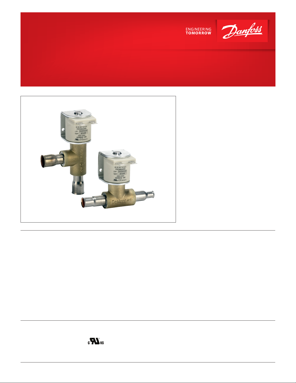
Solenoid valves
Type EVU for fluorinated refrigerants
EVU solenoid valves are designed to fit into
compact refrigeration systems. Available in direct
and servo operated versions, they can be applied
in liquid, suction, and hot gas lines with fluorinated
refrigerants.
EVU solenoid valves can be used in many different
refrigeration systems and are specially designed for:
y commercial refrigeration systems
y refrigeration appliances
y liquid coolers
y ice cube machines
y mobile refrigeration systems
y heat pump systems
y air conditioning units
EVU valves are available in straightway
or angleway design. All valves are semi hermetically
sealed and are not serviceable. The standard coil is
available with 3-core cable connection, DIN plug
and 0.25 US spade.
EVU valve bodies and coils are ordered separately.
Features
Approvals
© Danfoss | DCS (az) | 2018.06
y Compact construction small dimensions,
low weight for both valve and coil.
y Semi-hermetic construction. Metallic sealing
between armature tube and valve body. Bimetal
connections to the brass
housing Benefits:
– high strength of joints and high
vibration resistance
− maximum external tightness within
the whole temperature and pressure
operation range
y Bimetal connections simple, fast soldering
without the need of wet cloth or
refrigration pliers.
• UL Recognized Component (Canadian and US)
y Direct and servo operated mini piston compact
solenoid valve.
y Universal application for
− liquid, suction, and hot gas applications
− reduced power consumption
y Simple and fast mounting of coil
− clip - ON / OFF
y Small encapsulated coils with long life time
under extreme conditions.
y Refrigerants:
R744, R22 / R407C, R404A / R507, R410A,
R134a, R407A, R23.
For other refrigerants, please contact Danfoss.
y Large MOPD range − up to 36 bar.
• Pressure Equipment Directive (PED) 2014/68/EU
• Low Voltage Directive (LVD) 2014/35/EU
DKRCC.PD.BD0.4A.22 | 1
Page 2
Data sheet | Solenoid valve, type EVU for fluorinated refrigerants
Technical data
Refrigerants
R744, R22 / R407C, R404A / R507, R410A, R134a,
Ambient temperature
-40 – 140 °F
R407A, R23.
For other refrigerants, please contact Danfoss.
OPD operating range
M
0.029 psi up to 522 psi
Temperature of medium
-40 – 221 °F
Humidity
0 − 100% R.H. (0-97% R.H. non-condensation
condition if IP level is below IPX5).
Opening differential pressure
with standard coil p
Typ e
Min.
[psi]
Max. (=MOPD) liquid
8 W AC [°F] [psi] [gal / min]
EVU 1 0.000 348
3)
2
Temperature
of medium
Max. working
pressure
C
-40 – 221 1015 0.11
– value 1
v
EVU 2 0.029 522 -40 – 221 1015 0.23
EVU 3 0.029 522 -40 – 221 1015 0.35
EVU 4 0.029 522 -40 – 221 1015 0.58
EVU 5 0.029 522 -40 – 221 1015 0.76
EVU 6 0.029 522 -40 – 221 1015 0.93
EVU 8 0.029 522 -40 – 221 1015 1.15
1
Cv value is the water flow in [gal / min] at a pressure drop across valve p = 1 psi, ρ = 10 lbs / gal
2
MOPD for media in gas form is approximately 14 psi greater
3
For coil 208 – 240 V, 60 Hz, MOPD is 250 psi
MOPD (Max. Opening Pressure Differential) is measured with highest media and ambient temperature and
15% below nominal voltage
Metric conversions:
• 1 psi = 0.07 bar
•5/9 (t1 °F -32) = 12 °C
• 1 TR = 3.5 Kw
• 1 in = 25.4 mm
• 1 ft = 0.3 m
• 1 lb = 0.454 kg
• 1 oz = 28.35 gram
• US gal / min = 0.86 m3 / h
1
/ [TR]
R404A /
R507
R410A
R22 /
R407C
R134a
R404A
/ R507
R410A
Typ e
R22 /
R407C
Rated capacity
Liquid Suction vapour Hot gas
R134a
R404A
/ R507
R410A
R22 /
R407C
R134a
EVU 1 0.64 0.48 0.44 0.64 0.55 0.04 0.05 0.06 0.12 0.10 0.10 0.18
EVU 2 1.27 0.96 0.87 1.27 0.11 0.08 0.09 0 .13 0.24 0 .19 0.19 0.36
EVU 3 1.9 0 1.45 1.31 1.90 0.16 0.12 0.14 0.19 0.35 0.29 0.28 0.53
EVU 4 3 .19 2 .41 2.18 3.17 0.26 0.20 0.23 0.32 0.59 0.48 0.47 0.89
EVU 5 4 .12 3.13 2.83 4.12 0.34 0.26 0.30 0.42 0.76 0.62 0. 61 1.16
EVU 6 5.07 3.86 3.49 5.07 0.42 0.32 0.37 0.51 0.94 0.77 0.76 1.42
EVU 8 6.34 4.83 4.36 6.34 0.53 0.40 0.46 0.64 1.18 0.96 0.95 1.78
1
Rated liquid and suction vapor capacity are based on:
- evaporating temperature t
- liquid temperature ahead of valve t
- pressure drop p across valve
- with liquid p = 2 psi for R134a, p = 3 psi for R22 / R407C, R404A and R507
with suction vapor p = 1 psi
-
Rated hot gas capacity is based on:
- condensing temperature t
- hot gas temperature th = 140 °F
- pressure drop across valve p = 2 psi
= 40 °F
e
= 100 °F
c
= 100 °F
l
© Danfoss | DCS (az) | 2018.06
DKRCC.PD.BD0.4A.22 | 2
Page 3
Data sheet | Solenoid valve, type EVU for fluorinated refrigerants
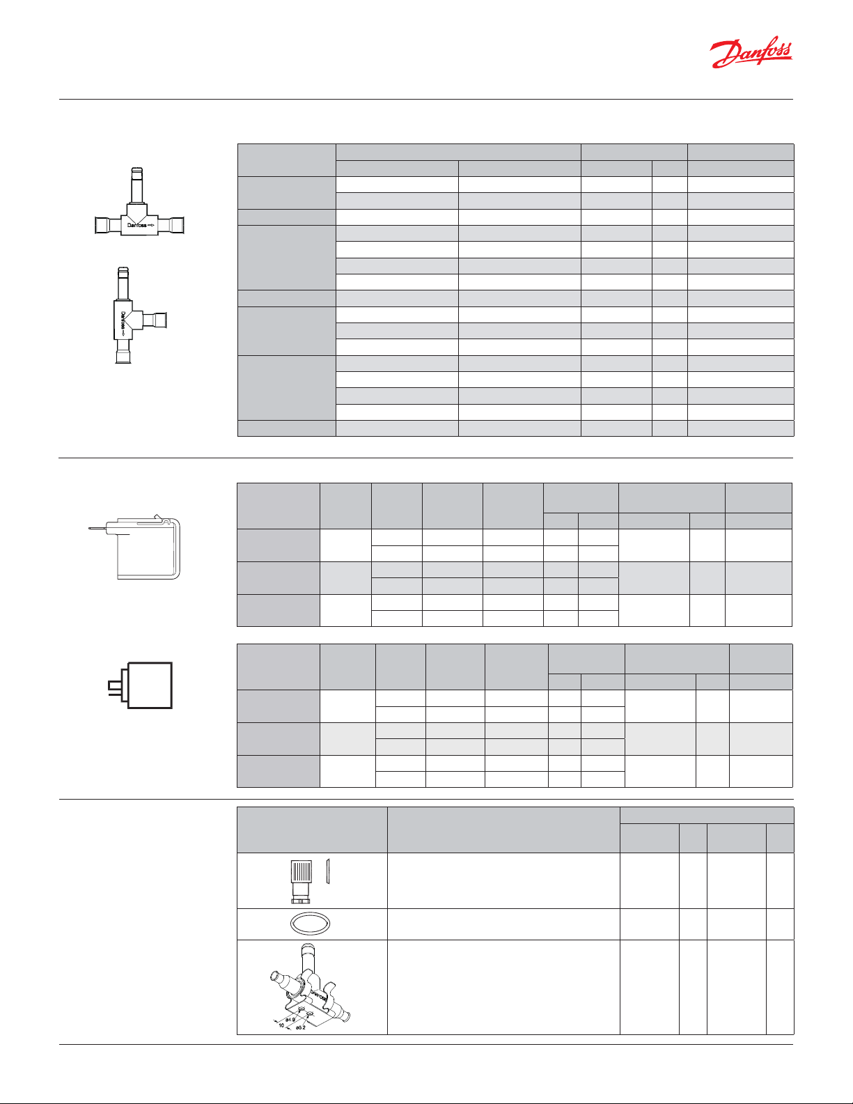
Ordering valve
EVU 1– EVU 6
EVU 8
Single pack
1 product in a box with installation guide
Multi pack
box with x pieces single pack
(can be split)
Industrial pack
x pieces in one box (cannot be split)
0.25 in. US spade connections
0.25 in. US spade connection
Single pack
1 product in a box with installation guide
Multi pack
box with x pieces single pack
(can be split)
Industrial pack
x pieces in one box (cannot be split)
Normally closed NC
Typ e
[in.] [mm] Code no. Pcs. Code no.
EVU 1
EVU 2 – 6 032F5053 40 032F9529
EVU 3
EVU 4 – 10 032F5037 40 032F9531
EVU 5
EVU 6
EVU 8 – 12 032F8009 40 –
The valve code numbers on above are with coil sealing O-ring. This should be removed For US-coils with the external Frame.
Connection Industrial pack Mutiple pack
1
4
/
– 032F7005 40 032F9524
– 6 032F7004 40 –
1
4
/
– 032F5024 40 032F9525
– 6 032F5025 40 032F9530
3
8
/
– 032F5026 40 03 2F5111
– 10 032F5027 40 –
3
8
/
– 032F7000 40 032F9526
– 10 032F7001 40 032F9532
– 12 032F7003 40 –
3
8
/
– 032F5046 40 032F9527
– 10 032F50 47 40 –
1
2
/
– 032F50 49 40 032F9528
– 12 032F5048 40 032F9533
Alternating current AC with US spade IP00
Typ e
Tem p.
[°C]
AY240C -40 – 50
AY120C -40 – 50
AY02 4C -40 – 50
Ambient
Supply
voltage
[V]
Voltage
variation
Frequency
[Hz]
208 – 240 -15% – 10% 50 8.0 16
208 – 240 -15% – 10% 60 8.0 16
110 – 120 -15% – 10% 50 8.0 16
110 – 120 -15% – 10% 60 8.0 16
24 -15% – 10% 50 8.0 16
24 -15% – 10% 60 8.0 16
Power
consumption
Industrial pack Multi pack
[W] [VA] Code no. Pcs. Code no.
042N8230 40 042N4230
042N8233 40 042N4233
042N8236 40 –
Alternating current AC with US DIN spade IP00
Typ e
Tem p.
[°C]
AZ240CS -40 – 50
AZ120C S -40 – 50
AZ024CS -40 – 50
Ambient
Supply
voltage
[V]
Voltage
variation
Frequency
[Hz]
230 -15% – 10% 50 8.0 16
208 – 240 -15% – 10% 60 7. 0 14
115 -15% – 10% 50 8.5 16
110 – 120 -15% – 10% 60 7. 0 14
24 -15% – 10% 50 9.5 18
24 -15% – 10% 60 7. 0 14
Power
consumption
Industrial pack Multi pack
[W] [ VA] Code no. Pcs. Code no.
042N8201 40 042N4201
042N8202 40 042N4202
042N8203 40 042N4203
Accessories
© Danfoss | DCS (az) | 2018.06
Part Description
DIN plug (EN175301-803 type A)
O-ring for sealing the coil. Industrial pack (50 pcs.)
NB: Valve body suppplied with O-ring
.FW
Danfoss
32M20.10
Bracket for fixing of valve. – 032F8036 40
Code no.
Multi
pack
Pcs.
Industrial
pack
042N 0156 –
03 2F6115 –
DKRCC.PD.BD0.4A.22 | 3
Pcs.
Page 4
Data sheet | Solenoid valve, type EVU for fluorinated refrigerants
Capacity
Liquid capacity
[TR]
o
Typ e
Liquid capacity Q
at pressure drop across valve p [bar]
1 2 3 4 5 6 7
R22 / R407C
EVU 1 0.34 0.52 0.64 0.73 0.82 0.85 0.97
EVU 2 0.68 1.03 1.27 1.46 1.63 1.79 1.93
EVU 3 1.02 1.55 1.90 2.19 2.45 2.69 2.90
EVU 4 1.69 2.59 3 .17 3.66 4.09 4.48 4.84
EVU 5 2.20 3.36 4 .12 4.75 5. 31 5.83 6.29
EVU 6 2.71 4.14 5.07 5.85 6.54 7.17 7.74
EVU 8
3.39 5.18 6.34 7. 31 8.18 8.96 9.68
R134A
EVU 1
EVU 2 0.68 0.96 1.18 1.3 6 1.52 1.67 1.80
EVU 3 1.02 1.45 1.77 2.05 2.29 2.51 2.71
EVU 4 1.71 2. 41 2. 59 3. 41 3.81 4.18 4.84
EVU 5
EVU 6 2.73 3.86 4.73 5.45 6 .10 6.68 7. 22
EVU 8 3.41 4.83 5.91 6. 81 7.63 8.35 9.03
0.34 0.48 0.59 0.68 0.76 0.84 0.90
2.22 3 .13 3.84 4.43 4.96 5.43 5.86
R404A/507
EVU 1 0.25 0.36 0.44 0. 51 0.57 0.62 0.67
EVU 2 0.50 0.71 0.87 1. 01 1.13 1.23 1. 33
EVU 3 0.76 1.07 1. 31 1. 51 1. 69 1. 85 2.00
EVU 4 1.26 1.78 2.18 2.52 2.81 3.09 3.33
EVU 5
EVU 6 2.02 2.85 3.49 4.03 4.50 4.94 5.33
EVU 8 2.53 3.56 4.36 5.04 5.63 6.18 6.66
1.6 4 2. 31 2.83 3.27 3.66 4.01 4.33
Metric conversions
• 1 psi = 0.07 bar
• 5/9 (t1 °F - 32) = t2 °C
• 1 TR = 3.5 kW
© Danfoss | DCS (az) | 2018.06
R410a
EVU 1 0.34 0.52 0.64 0.73 0.82 0.90 0.97
EVU 2 0.68 1.03 1.27 1.46 1.63 1.79 1.93
EVU 3 1.02 1.55 1.90 2.19 2.44 2.69 2.90
EVU 4 1.69 2.59 3 .17 3.66 4.07 4.48 4.84
EVU 5 2.20 3.36 4 .12 4.75 5.29 5.83 6.29
EVU 6
EVU 8 3.39 5.18 6.34 7. 31 8 .14 8.96 9.68
Capacities are based on:
- liquid temperature tl = 100 °F,
- evaporating temperature te = 40 °F,
- superheat temperature (te + 10 °F) = 50 °F.
Correction factors for liquid temperature t
tl [°F] 80 90 100 110 120
Factor 1.10 1.05 1.0 0 0.95 0.90
When liquid temperature t
multiplying them by the appropriate correction factor found in the following table.
2.71 4.14 5.07 5.85 6.51 7.17 7.74
l
ahead of the expansion valve is other than 100 °F, adjust the table capacities by
l
DKRCC.PD.BD0.4A.22 | 4
Page 5

Data sheet | Solenoid valve, type EVU for fluorinated refrigerants
Capacity
Suction vapour capacity
Typ e
EVU 1
EVU 2
EVU 3
EVU 4
EVU 5
Pressure
drop p
[psi]
-40
-20 0 10 20 30 40 50
Suction vapour capacity Qe [TR]
at evaporating temperature te [°F]
R22 / R407C
1.0 0 0.02 0.03 0.04 0.04 0.05 0.05 0.06 0.08
2.00 0.03 0.04 0.05 0.06 0.06 0.07 0.08 0.08
3.00 0.03 0.05 0.06 0.07 0.07 0.08 0.09 0.10
1.0 0 0.04 0.05 0.07 0.08 0.09 0.09 0 .11 0.12
2.00 0.05 0.07 0.09 0 .11 0.12 0 .13 0.15 0.16
3.00 0.06 0.09 0 .11 0.13 0.14 0.16 0 .18 0.20
1.0 0 0.06 0.08 0 .10 0.12 0 .13 0.14 0.16 0 .17
2.00 0.08 0 .11 0.14 0.16 0.18 0.20 0.22 0.25
3.00 0.09 0.13 0 .17 0.19 0.22 0.25 0.27 0.30
1.0 0 0.10 0.14 0 .17 0.19 0. 21 0.24 0.26 0.29
2.00 0 .13 0.18 0.23 0.27 0.30 0.34 0.37 0.41
3.00 0.16 0.22 0.28 0.32 0.36 0.41 0.45 0.50
1.0 0 0.13 0.18 0.22 0.25 0.28 0.31 0.34 0.37
2.00 0 .17 0.24 0.30 0.35 0.39 0.44 0.48 0.53
Metric conversions
• 1 psi = 0.07 bar
• 5/9 (t1 °F - 32) = t2 °C
• 1 TR = 3.5 kW
3.00 0.20 0.28 0. 37 0.41 0.47 0.54 0.59 0.65
1.0 0 0.16 0.22 0. 27 0.31 0.34 0.38 0.42 0.46
EVU 6
EVU 8
The table values refer to evaporator capacity and are given as a function of:
- evaporating temperature te ,
- pressure drop p across the valve.
Capacities are based on:
- liquid temperature tl = 100 °F ahead of the expansion valve,
- superheat ts = 7 °F.
For each additional 10 °F of superheat, the table capacities must be reduced by 2%.
Correction factors for liquid temperature t
tl [°F] 80 90 10 0 110 120
Factor 1.10 1.05 1. 00 0.95 0.90
When liquid temperature t
2.00 0.21 0.29 0.37 0.44 0.48 0.54 0.59 0.65
3.00 0.25 0.35 0.45 0.51 0.57 0.66 0.73 0.80
1.0 0 0.20 0.28 0.34 0.39 0.43 0.48 0.53 0.58
2.00 0.26 0.36 0.46 0.55 0.60 0.68 0 .74 0.81
3.00 0. 31 0.44 0.56 0.64 0.71 0.83 0.91 1.00
l
ahead of the expansion valve is other than 100 °F, adjust the table capacities by
l
multiplying them by the appropriate correction factor found in the following table.
© Danfoss | DCS (az) | 2018.06
DKRCC.PD.BD0.4A.22 | 5
Page 6

Data sheet | Solenoid valve, type EVU for fluorinated refrigerants
Capacity
Suction vapour capacity
(continued)
Typ e
EVU 1
EVU 2
EVU 3
EVU 4
EVU 5
Pressure
drop p
[psi]
1.0 0 0.01 0.02 0.03 0.03 0.03 0.04 0.04 0.05
2.00 0.02 0.03 0.04 0.04 0.05 0.05 0.06 0.07
3.00 0.02 0.03 0.04 0.05 0.05 0.06 0.07 0.08
1.0 0 0.02 0.03 0.05 0.06 0.06 0.07 0.08 0.09
2.00 0.03 0.05 0.07 0.08 0.09 0.10 0 .11 0.13
3.00 0.03 0.05 0.08 0.09 0.10 0.12 0.13 0 .16
1.0 0 0.04 0.05 0.07 0.08 0.10 0 .11 0.12 0 .14
2.00 0.05 0.07 0.10 0.11 0.13 0 .15 0 .17 0.19
3.00 0.05 0.08 0 .12 0.14 0.16 0 .18 0.20 0.23
1.0 0 0.06 0.09 0.12 0 .14 0.16 0.18 0.20 0.23
2.00 0.08 0.12 0.16 0.19 0.22 0.25 0.29 0.32
3.00 0.09 0.13 0.19 0.23 0.26 0.30 0.34 0.39
1.0 0 0.08 0 .11 0.16 0.18 0 .21 0.23 0.26 0.29
2.00 0.10 0.15 0.21 0.24 0.28 0.33 0.37 0.42
-40
-20 0 10 20 30 40 50
Suction vapour capacity Qe [TR]
at evaporating temperature te [°F]
R134a
Metric conversions
• 1 psi = 0.07 bar
• 5/9 (t1 °F - 32) = t2 °C
• 1 TR = 3.5 kW
3.00 0.11 0.17 0.25 0.29 0.34 0.39 0.44 0.51
1.0 0 0.10 0.14 0.20 0.22 0.25 0.29 0.32 0.36
EVU 6
EVU 8
The table values refer to evaporator capacity and are given as a function of:
- evaporating temperature te ,
- pressure drop p across the valve.
Capacities are based on:
- liquid temperature tl = 100 °F ahead of the expansion valve,
- superheat ts = 7 °F.
For each additional 10 °F of superheat, the table capacities must be reduced by 2%.
Correction factors for liquid temperature t
tl [°F] 80 90 100 110 120
Factor 1.10 1. 05 1.00 0.95 0.90
When liquid temperature t
2.00 0 .13 0.19 0.26 0.30 0.35 0 .41 0.46 0 .51
3.00 0.14 0.21 0.31 0.36 0.41 0.48 0.54 0.63
1.0 0 0.13 0.18 0.25 0.28 0. 31 0.36 0.40 0.45
2.00 0.16 0. 24 0.33 0.38 0.44 0.51 0.58 0.64
3.00 0.18 0.26 0.39 0.45 0.51 0.60 0.68 0.79
l
ahead of the expansion valve is other than 100 °F, adjust the table capacities by
l
multiplying them by the appropriate correction factor found in the following table.
© Danfoss | DCS (az) | 2018.06
DKRCC.PD.BD0.4A.22 | 6
Page 7

Data sheet | Solenoid valve, type EVU for fluorinated refrigerants
Capacity
Suction vapour capacity
(continued)
Typ e
EVU 1
EVU 2
EVU 3
EVU 4
EVU 5
Pressure
drop p
[psi]
-40
-20 0 10 20 30 40 50
Suction vapour capacity Qe [TR]
at evaporating temperature te [°F]
R404A/507
1.0 0 0.02 0.02 0.03 0.04 0.04 0.04 0.05 0.05
2.00 0.02 0.03 0.04 0.05 0.05 0.06 0.07 0.08
3.00 0.03 0.04 0.05 0.06 0.07 0.07 0.08 0.09
1.0 0 0.03 0.04 0.06 0.07 0.07 0.08 0.09 0.10
2.00 0.04 0.06 0.08 0.09 0 .10 0.12 0 .13 0.15
3.00 0.05 0.07 0 .10 0 .11 0.13 0.14 0.16 0.18
1.0 0 0.05 0.07 0.09 0.10 0 .11 0.12 0.14 0.16
2.00 0.06 0.09 0.12 0 .14 0 .16 0.18 0.20 0.22
3.00 0.08 0 .11 0.14 0.16 0 .19 0.22 0.24 0.27
1.0 0 0.08 0 .11 0.14 0.17 0.18 0.21 0.23 0.26
2.00 0 .11 0.15 0.20 0.23 0.26 0.29 0.33 0.37
3.00 0 .13 0.18 0.24 0.27 0.32 0.36 0.40 0.45
1.0 0 0.10 0.14 0 .19 0.22 0. 24 0.27 0.30 0.34
2.00 0.14 0 .19 0.27 0.30 0.34 0.38 0.43 0.48
Metric conversions
• 1 psi = 0.07 bar
• 5/9 (t1 °F - 32) = t2 °C
• 1 TR = 3.5 kW
3.00 0.16 0.23 0.31 0.36 0.41 0.47 0.52 0.58
1.0 0
EVU 6
EVU 8
The table values refer to evaporator capacity and are given as a function of:
- evaporating temperature te ,
- pressure drop p across the valve.
Capacities are based on:
- liquid temperature tl = 100 °F ahead of the expansion valve,
- superheat ts = 7 °F.
For each additional 10 °F of superheat, the table capacities must be reduced by 2%.
2.00
3.00
1.0 0
2.00
3.00
Correction factors for liquid temperature t
tl [°F] 80 90 10 0 110 120
Factor 1.10 1.05 1. 00 0.95 0.90
When liquid temperature t
0.13 0 .17 0.23 0. 27 0.29 0.33 0. 37 0. 41
0.17 0.24 0.33 0.37 0.42 0.47 0.52 0. 59
0.20 0.28 0.38 0.44 0.51 0.58 0.64 0.72
0.16 0.21 0.29 0.34 0.36 0.41 0.46 0 .51
0.21 0.30 0 .41 0.46 0.53 0. 59 0.65 0.74
0.25 0.35 0.48 0.55 0.64 0.73 0.80 0.90
l
ahead of the expansion valve is other than 100 °F, adjust the table capacities by
l
multiplying them by the appropriate correction factor found in the following table.
© Danfoss | DCS (az) | 2018.06
DKRCC.PD.BD0.4A.22 | 7
Page 8

Data sheet | Solenoid valve, type EVU for fluorinated refrigerants
Capacity
Suction vapour capacity
(continued)
Metric conversions
• 1 psi = 0.07 bar
• 5/9 (t1 °F - 32) = t2 °C
• 1 TR = 3.5 kW
Typ e
EVU 1
EVU 2
EVU 3
EVU 4
EVU 5
EVU 6
EVU 8
The table values refer to evaporator capacity and are given as a function of:
- evaporating temperature te ,
- pressure drop p across the valve.
Capacities are based on:
- liquid temperature tl = 100 °F ahead of the expansion valve,
- superheat ts = 7 °F.
For each additional 10 °F of superheat, the table capacities must be reduced by 2%.
Pressure
drop p
[psi]
1.0 0
2.00
3.00
1.0 0
2.00
3.00
1.0 0
2.00
3.00
1.0 0
2.00
3.00
1.0 0
2.00
3.00
1.0 0
2.00
3.00
1.0 0
2.00
3.00
-40 -20 0 10 20 30 40 50
0,03 0.04 0.05 0.05 0.06 0.06 0.07 0.08
0.04 0.05 0.06 0.07 0.08 0.09 0 .10 0 .11
0.05 0.06 0.08 0.08 0 .10 0 .11 0.12 0.13
0.05 0.07 0.09 0.10 0 .11 0.12 0.13 0 .15
0.07 0.10 0 .12 0.14 0.16 0.17 0.19 0.21
0.09 0.12 0.15 0 .16 0.19 0. 21 0.23 0.25
0.08 0 .11 0.13 0.15 0 .17 0.18 0.19 0.22
0.11 0.15 0.18 0. 21 0.23 0.26 0.28 0.31
0.13 0 .17 0.22 0.25 0.28 0 .31 0.34 0.38
0.14 0.18 0.22 0.25 0.28 0.30 0.32 0.36
0.18 0.24 0. 31 0.35 0.39 0.43 0.47 0.52
0.22 0.29 0.37 0 .41 0.47 0.52 0.56 0.63
0.18 0.23 0.29 0.32 0.36 0.39 0.42 0.47
0.24 0.31 0.40 0.46 0.51 0.55 0.60 0.67
0.29 0.38 0.48 0.54 0.60 0.68 0.73 0.82
0.22 0.29 0.36 0.40 0.45 0.48 0.51 0.58
0.30 0.39 0.49 0.56 0.62 0.68 0 .74 0.82
0.35 0.46 0.59 0.66 0.74 0.84 0.90 1. 01
0.28 0.36 0.45 0.50 0.56 0.60 0.64 0.73
0.38 0.49 0 .61 0.70 0.78 0.85 0.93 1.03
0.44 0.58 0.74 0,83 0.93 1. 05 1.13 1.26
Suction vapour capacity Qe [TR]
at evaporating temperature te [°F]
R410A
© Danfoss | DCS (az) | 2018.06
Correction factors for liquid temperature t
tl [°F] 80 90 10 0 110 120
Factor 1.10 1.05 1. 00 0.95 0.90
When liquid temperature t
ahead of the expansion valve is other than 100 °F, adjust the table capacities by
l
l
multiplying them by the appropriate correction factor found in the following table.
DKRCC.PD.BD0.4A.22 | 8
Page 9

Data sheet | Solenoid valve, type EVU for fluorinated refrigerants
Capacity
Hot gas capacity
Typ e
EVU 1
EVU 2
Pressure
drop
across
valve
p
[psi]
2 0,11 0 ,12 0,13 0.09 0.10 0.10 0.09 0.10 0.09 0.17 0.18 0.17
5 0.17 0 .19 0.20 0.14 0.16 0.16 0.15 0.15 0.15 0.27 0.29 0. 27
10 0. 24 0.27 0.29 0 .19 0.22 0.23 0.20 0.22 0.21 0.36 0.38 0.38
15 0.29 0.32 0.36 0.24 0.26 0.29 0.25 0.26 0.26 0.45 0.48 0.48
20 0.33 0.37 0.40 0.28 0.31 0.32 0.28 0.30 0.29 0.52 0.55 0.54
25 0.37 0.41 0.44 0 .31 0.34 0.36 0.32 0.33 0.32 0.58 0.62 0.60
2 0.21 0.24 0.25 0.17 0.19 0.20 0.18 0.19 0.18 0.34 0.36 0.34
5 0.34 0.38 0.40 0.28 0.31 0.32 0.29 0.30 0.29 0.54 0.57 0.54
10 0.47 0.54 0.57 0.38 0.43 0.46 0.40 0.43 0.42 0.72 0.76 0.75
15 0.57 0.63 0.71 0.47 0.52 0.57 0.49 0. 51 0. 51 0.90 0.96 0.96
20 0.66 0.73 0.79 0.55 0. 61 0.64 0.56 0.59 0.57 1.03 1.10 1. 07
25 0.73 0.82 0.88 0 . 61 0.68 0.72 0.63 0.66 0.64 1.16 1.23 1.19
2 0.32 0.35 0.38 0.26 0.29 0.30 0. 27 0.28 0.27 0.50 0.53 0.51
Evaporating temp. te = 40 °F, hot gas temp. th = tc + 40 °F, subcooling tu = 10 °F
R22 / R407C R13 4a R404A/R 507 R410A
70 100 140 70 100 140 70 100 140 70 100 140
Hot gas capacity Qh [TR]
Condensing temp. t
c
[°F]
Metric conversions
• 1 psi = 0.07 bar
• 5/9 (t1 °F - 32) = t2 °C
• 1 TR = 3.5 kW
5 0.51 0.56 0.60 0.42 0.46 0.48 0.43 0.45 0.44 0.81 0.85 0. 81
EVU 3
EVU 4
The table values refer to hot gas capacity and are given as a function of:
- condensing temperature tc,
- pressure drop p across the valve.
Capacities are based on:
- hot gas temperature superheated 40 °F above condensing temperature (th = tc + 40 °F).
For each additional 10 °F of superheat above 40 °F, the table capacities must be reduced by 1%.
Correction factors for th and t
tl [°F] -40 -20 0 20 40 50
Factor 1.18 1.14 1.09 1.04 1 0.97
10 0.71 0.81 0.86 0.58 0.64 0.69 0.60 0.65 0.62 1.0 8 1.14 1.12
15 0.86 0.95 1.06 0.71 0.79 0.85 0.73 0.77 0.77 1.36 1.44 1.44
20 0.99 1.10 1.19 0.82 0.91 0.96 0.84 0.88 0.86 1.55 1.64 1.61
25 1.10 1. 22 1. 32 0.92 1.02 1.08 0.95 0.99 0.96 1.74 1.85 1.79
2 0.53 0.59 0.63 0.44 0.48 0.50 0.45 0.47 0.46 0.84 0.89 0.85
5 0.85 0.94 1.0 0 0.70 0.77 0.80 0.72 0.75 0.73 1.35 1.42 1.36
10 1.18 1. 35 1.43 0.96 1.07 1.15 1.00 1.08 1. 04 1. 80 1.91 1.87
15 1.43 1. 59 1.7 7 1.18 1. 31 1.42 1.22 1.28 1.28 2.26 2.40 2.39
20 1. 64 1.83 1.98 1. 37 1.52 1.6 0 1.41 1.47 1.43 2.58 2 .74 2.69
25 1. 83 2.04 2.21 1.53 1.70 1.8 0 1.58 1.65 1.60 2.89 3.08 2.98
e
When the valve is used in a hot gas defrost circuit, evaporator temperature affects the capacity.
When the evaporator temperature differs from 40 °F, adjust the table capacities by multiplying them by the
appropriate correction factor found in the following table.
© Danfoss | DCS (az) | 2018.06
DKRCC.PD.BD0.4A.22 | 9
Page 10

Data sheet | Solenoid valve, type EVU for fluorinated refrigerants
Capacity
Hot gas capacity
Metric conversions
• 1 psi = 0.07 bar
• 5/9 (t1 °F - 32) = t2 °C
• 1 TR = 3.5 kW
Pressure
drop
Typ e
EVU 5
EVU 6
EVU 8
The table values refer to hot gas capacity and are given as a function of:
- condensing temperature tc,
- pressure drop p across the valve.
Capacities are based on:
- hot gas temperature superheated 40 °F above condensing temperature (th = tc + 40 °F).
For each additional 10 °F of superheat above 40 °F, the table capacities must be reduced by 1%.
across
valve
p
[psi]
2 0.69 0.76 0.82 0.57 0.62 0.65 0.59 0.61 0.59 1.09 1.16 1.11
5 1. 11 1. 22 1.31 0.91 1. 00 1.04 0.94 0.98 0.94 1.75 1. 84 1.76
10 1. 53 1.75 1.86 1.25 1.39 1.49 1. 29 1.41 1.35 2.35 2.48 2.44
15 1. 86 2.06 2.30 1.53 1.70 1.85 1. 59 1.66 1.67 2.94 3 .12 3 .11
20 2.14 2.38 2.57 1.78 1.97 2.08 1.83 1.91 1.86 3.35 3.56 3.49
25 2.38 2.65 2.87 1.99 2.21 2.34 2.06 2.15 2.08 3.76 4.01 3.88
2 0.85 0.94 1.01 0.70 0.77 0.80 0.72 0.76 0.73 1.35 1.42 1.37
5 1.36 1.50 1.61 1.12 1. 23 1.28 1.16 1.21 1.16 2.16 2.27 2.17
10 1.88 2.15 2.29 1.54 1.71 1. 84 1.59 1.73 1.66 2.89 3.05 3.00
15 2.29 2.54 2.84 1. 89 2.10 2.28 1.96 2.04 2.05 3.62 3.83 3.83
20 2.63 2.93 3.16 2.19 2.43 2.56 2.25 2.35 2.29 4.12 4.38 4.30
25 2.93 3.27 3.53 2.45 2.72 2.88 2.53 2.65 2.56 4.63 4.93 4.77
2 1.06 1.18 1.26 0.88 0.96 1. 00 0.90 0.95 0.91 1.69 1.78 1.71
5 1.70 1.88 2. 01 1.40 1.54 1.60 1.45 1.51 1.45 2.70 2.84 2.71
10 2.35 2.69 2.86 1.93 2.14 2.30 1.99 2.16 2.08 3 .61 3.81 3.75
15 2.86 3.18 3.55 2.36 2.63 2.85 2.45 2.55 2.56 4.53 4.79 4.79
20 3.29 3.66 3.95 2.74 3.04 3.20 2.81 2.94 2.86 5.15 5.48 5.38
25 3.66 4.09 4 .41 3.06 3.40 3.60 3.16 3.68 3.20 5.79 6 .16 5.96
Evaporating temp. te = 40 °F, hot gas temp. th = tc + 40 °F, subcooling tu = 10 °F
R22 / R407C R134a R404A/R 507 R410A
70 10 0 140 70 100 140 70 100 140 70 100 14 0
Hot gas capacity Qh [TR]
Condensing temp. t
c
[°F]
© Danfoss | DCS (az) | 2018.06
Correction factors for th and t
tl [°F] -40 -20 0 20 40 50
Factor 1.18 1.14 1.09 1.04 1 0.97
e
When the valve is used in a hot gas defrost circuit, evaporator temperature affects the capacity.
When the evaporator temperature differs from 40 °F, adjust the table capacities by multiplying them by the
appropriate correction factor found in the following table.
DKRCC.PD.BD0.4A.22 | 10
Page 11

Data sheet | Solenoid valve, type EVU for fluorinated refrigerants
Design / Function
1. Solder connection
5. Solder connection
2. Solder ring
4. Solder ring
3. Valve housing
6. Union nut
7. Armature tube
8. Return spring
9. Armature
10. Support ring
11. Pilot plate (servo)
12. Seat plate (servo)
13. Piston (servo)
Direct operated
EVU 1 is direct operated. The valve opens directly
for full flow when the armature (9) moves up into
the magnetic field of the coil.
This means that the valve can operate at 0 bar
differential pressure. Thus, inlet pressure and spring
force act to close the valve when the coil is
currentless.
Servo operated
EVU 2 - 8 are servo operated piston solenoid valves.
The servo piston principle results in a fast
operating and compact valve that is able to open
against a high differential pressure. The valve
closes rather soft, because the pilot system does
not fully close before the main orifice has closed.
This minimizes liquid hammer.
When the coil is currentless, the main orifice, seat
plate (12) and pilot orifice (on the pilot plate (11))
are closed. The pilot orifice and main orifice are
held closed by the armature spring force and the
differential pressure between inlet and outlet sides.
Servo operatedDirect operated
When current is applied to the coil, the armature (9)
is drawn up into the magnetic field and thus lifts
the pilot plate (11) and opens for the pilot orifice so
that the de-energising of the servo chamber (A)
starts and the pressure is relieved to the level of the
outlet side. As the inlet pressure that acts on the
bottom of the piston (13) now is higher than the
pressure in the servo chamber (A), the piston is
moved upwards and lifts both the pilot plate (11)
and the seat plate (12). When the seat plate is lifted,
the main orifice opens for full flow.
Therefore a minimum differential pressure of 0.02
bar is necessary to open the valve and keep it open.
When the current to the coil is switched off, the
spring (8) forces the armature (9) down towards the
pilot plate (11). The pressure in the servo chamber (A)
increases and the piston will no longer be able to
hold the seat plate (12) in lifted position, by which the
main orifice closes. The armature (9) continues its
downwards movement until the pilot orifice on the
pilot plate (11) is fully closed.
Material specifications
© Danfoss | DCS (az) | 2018.06
No. Description Material Alloys Mat. no.
1, 5 Bi-metallic tube Stainless steel / Cu – – – – –
2, 4 Solder ring Silver L-Ag 15 P CP102 – 104 4 10 4 4
3 Valve body Brass CuZn40Pb2 C W617N 2.0402 17672-1 12165
6 Union nut Brass CuZn39Pb2 CW 612N 2.0380 176 72-1 1216 4
7 Armature tube Stainless steel X6 CrM oS17 – 1.4105 – 10 088
8 Spring Spring wire stainless X10CrN i18 -8 – 1.4310 – 10088
9 Armature Stainless steel X4Cr MoS18 – 1.410SI L – 1008 8
10 Support ring Te flon PTFE – – – –
11 Pilot plate Thermoplast PEEK – – – –
12 Seat plate Teflo n PTFE – – – –
13 Piston Brass CuZn39Pb2 C W612N 2.0380 17672-1 1216 4
W.no. DIN EN
Standard
DKRCC.PD.BD0.4A.22 | 11
Page 12

Dimensions [in.]
and weights [lbs]
EVU 1, EVU 2, EVU 3, EVU 4, EVU 5, EVU 6 mounted with coil with 0.25 in. US spade
ø1.18
EVU 1, EVU 2, EVU 3, EVU 4, EVU 5, EVU 6
Net weight of coil:
8 W: approx. 0.22 lbs
Net weight of valve:
appox 0.22 lbs
© Danfoss | DCS (az) | 2018.06
EVU 8
Note: the drawings are only representative.
DKRCC.PD.BD0.4A.22 | 12
 Loading...