


Data sheet
Solenoid valves
Type EVU for fluorinated refrigerants
EVU solenoid valves are designed to fit into
compact refrigeration systems. Available in direct
and pilot operated versions, they can be applied in
liquid, suction, and hot gas lines with fluorinated
refrigerants.
EVU solenoid valves can be used in many different
refrigeration systems and are specially designed
for:
y commercial refrigeration systems
y refrigeration appliances
y liquid coolers
y ice cube machines
y mobile refrigeration systems
y heat pump systems
y air conditioning units
EVU valves are available in straightway
or angleway design. All valves are semi hermetically
sealed and are not serviceable. The standard coil is
available with 3-core cable connection, DIN plug
and 0.25 US spade.
EVU valve bodies and coils are ordered separately
in industrial pack.
Features y Compact construction small dimensions,
low weight for both valve and coil.
y Semi-hermetic construction. Metallic sealing
between armature tube and valve body. Bimetal
connections to the brass
housing Benefits:
– high strength of joints and high
vibration resistance
− maximum external tightness within
the whole temperature and pressure
operation range
y Bimetal connections simple, fast soldering
without the need of wet cloth or
refrigration pliers.
© Danfoss | DCS (rja) | 2016.02
y Direct and servo operated mini piston compact
solenoid valve.
y Universal application for
− liquid, suction, and hot gas applications
− reduced power consumption
y Simple and fast mounting of coil
− clip-on/off
y Small encapsulated coils with long life time
under extreme conditions.
y Refrigerants:
R744, R22/R407C, R404A/R507, R410A,
R134a, R407A, R23.
For other refrigerants, please contact Danfoss.
y Large MOPD range − up to 36 bar.
DKRCC.PD.BD0.1A.22 | 1

Data sheet | Product name, Solenoid valve, type EVU for fluorinated refrigerants
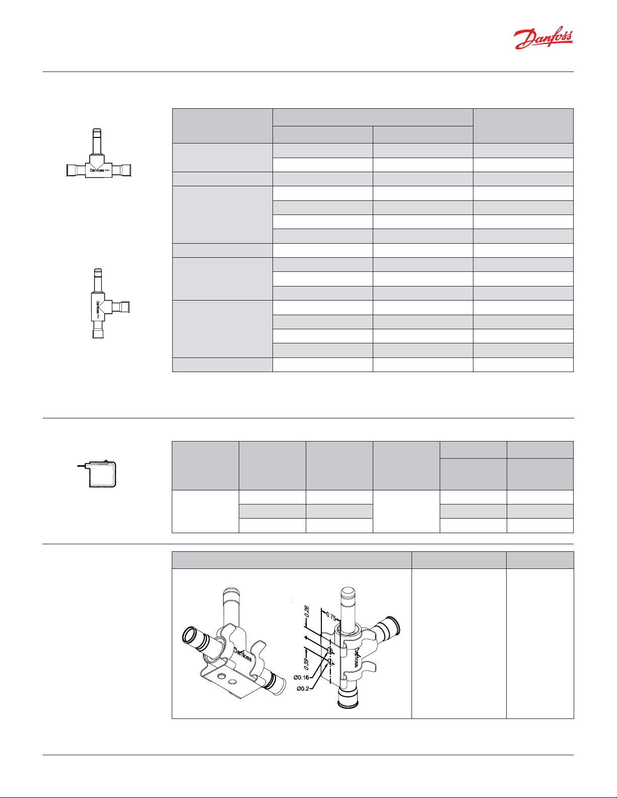
Approvals
Technical data
• UL Recognized Component (Canadian and US)
• PED (97/23/EC A3.P3)
• Low Voltage Directive (LVD) 2006/95/EC
Refrigerants
R744, R22/R407C, R404A/R507, R410A, R134a,
Ambient temperature
-40 – 140 °F
R407A, R23.
For other refrigerants, please contact Danfoss.
MOPD operating range
EVU 1: 0 psi up to 275 psi
Temperature of medium
EVU 2 – 8: 0.029 psi up to 522 psi
-40 – 221 °F
Humidity
0 − 100% R.H. (0-97% R.H. non-condensation
condition if IP level is below IPX5).
Opening differential pressure
with standard coil
Typ e
Min.
EVU 1 0.000 348
EVU 2 0.029 522 -40 – 221 1015 0.23
EVU 3 0.029 522 -40 – 221 1015 0.35
EVU 4 0.029 522 -40 – 221 1015 0.58
EVU 5
EVU 6 0.029 522 -40 – 221 1015 0.93
EVU 8 0.029 522 -40 – 221 1015 1.15
1)
Cv value is the water flow in [gal/min] at a pressure drop across
valve ∆p = 1 psi, ρ = 10 lbs/gal
2)
MOPD for media in gas form is approximately 14 psi greater
3)
For coil 208 – 240V, 60 Hz, MOPD is 250 psi
0.029 522 -40 – 221 1015 0.76
∆p [psi]
Max. (=MOPD) liquid
8 W AC [°F] [psi] [gal/min]
3)
Temperature
of medium
2)
-40 – 221 1015 0. 11
MOPD (Max. Opening Pressure Differential) is
measured with highest media and ambient
temperature and 15% below nominal voltage
Max. working
pressure
Ps
Cv – value
1)
1)
Rated liquid and suction vapor
capacity are based on:
y Evaporating temperature te
= 40 °F
y Liquid temperature ahead
of valve tl = 100 °F
y Pressure drop ∆p across
valve
– with liquid ∆p = 2 psi for
R134a,
∆p = 3 psi for R22/R407C,
R404A and R507,
–
with suction vapor ∆p = 1 psi
Rated hot gas capacity is based
on:
y Condensing temperature tc
= 100 °F
y Hot gas temperature th =
140 °F
y Pressure drop across valve
∆p = 2 psi
© Danfoss | DCS (rja) | 2016.02
Rated capacity 1) / [TR]
Typ e
R22/
R407C
EVU 1 0.64 0.48 0.44 0.64 0.55 0.04 0.05 0.06 0.12 0.10 0.10 0.18
EVU 2 1.27 0.96 0.87 1.27 0.11 0.08 0.09 0.13 0. 24 0.19 0 .19 0.36
EVU 3 1.9 0 1.45 1.31 1.90 0.16 0.12 0.14 0.19 0.35 0.29 0.28 0.53
EVU 4 3 .19 2 .41 2.18 3.17 0.26 0.20 0.23 0.32 0.59 0.48 0.47 0.89
EVU 5 4 .12 3.13 2.83 4.12 0.34 0.26 0.30 0.42 0.76 0.62 0.61 1.16
EVU 6 5.07 3.86 3.49 5.07 0.42 0.32 0.37 0.51 0.94 0.77 0.76 1.42
EVU 8 6.34 4.83 4.36 6.34 0.53 0.40 0.46 0.64 1.18 0.96 0.95 1.78
Metric conversions
y 1 psi = 0.07 bar
y5/9 (t1 °F -32) = 12 °C
Liquid Suction vapour Hot gas
R134a
R404A/
R507
R410A
R22/
R407C
R134a
R404A/
R507
R410A
R22/
R407C
R134a
y 1 lb = 0.454 kg
y 1 oz = 28.35 gram
y US gal/min = 0.86 m3/h
R404A/
R507
R410A
y 1 TR = 3.5 Kw
y 1 in = 25.4 mm
y 1 ft = 0.3 m
DKRCC.PD.BD0.1A.22 | 2
Data sheet | Product name, Solenoid valve, type EVU for fluorinated refrigerants
Ordering valve
EVU 1– 6
EVU 8
Normally closed NC
4
4
8
8
8
2
Connection
Code no.
— 032F7005
— 032F5024
— 032F5026
— 032F7000
— 032F5046
— 032F50 49
Typ e
[in.] [mm]
1
EVU 1
/
— 6 032F7004
EVU 2 — 6 032F5053
1
/
EVU 3
— 6 032F5025
3
/
— 10 032F5027
EVU 4 — 10 032F5037
3
/
EVU 5
— 10 032F7001
— 12 032F7003
3
/
EVU 6
— 10 032F5047
1
/
— 12 032F5048
EVU 8 — 12 032F8009
The valve code numbers on above are with coil
sealing O-ring. This should be removed for
US-coils with the external frame.
Ordering Coils Alternating current AC
Typ e
0,25 in.
US spade
EVU 1, EVU 2,
EVU 3, EVU 4,
EVU 5, EVU 6,
EVU 8
Accessories
Voltage
[V]
208 – 240 50 / 60
110 – 120 50 / 60 042N8233 042N4233
24 50 / 60 042N8236 042N4236
Frequency
[Hz]
Power
consumption
Holding: 8 W
16 VA
Inrush: 32 VA
Code no. Code no.
Industrial pack
40-off with
US spade IP00
Single pack with
US spade IP00
042N8230 042N4230
Part Description Code no.
Bracket for fixing of valve.
Industrial pack
032F8036
© Danfoss | DCS (rja) | 2016.02
DKRCC.PD.BD0.1A.22 | 3
Data sheet | Product name, Solenoid valve, type EVU for fluorinated refrigerants
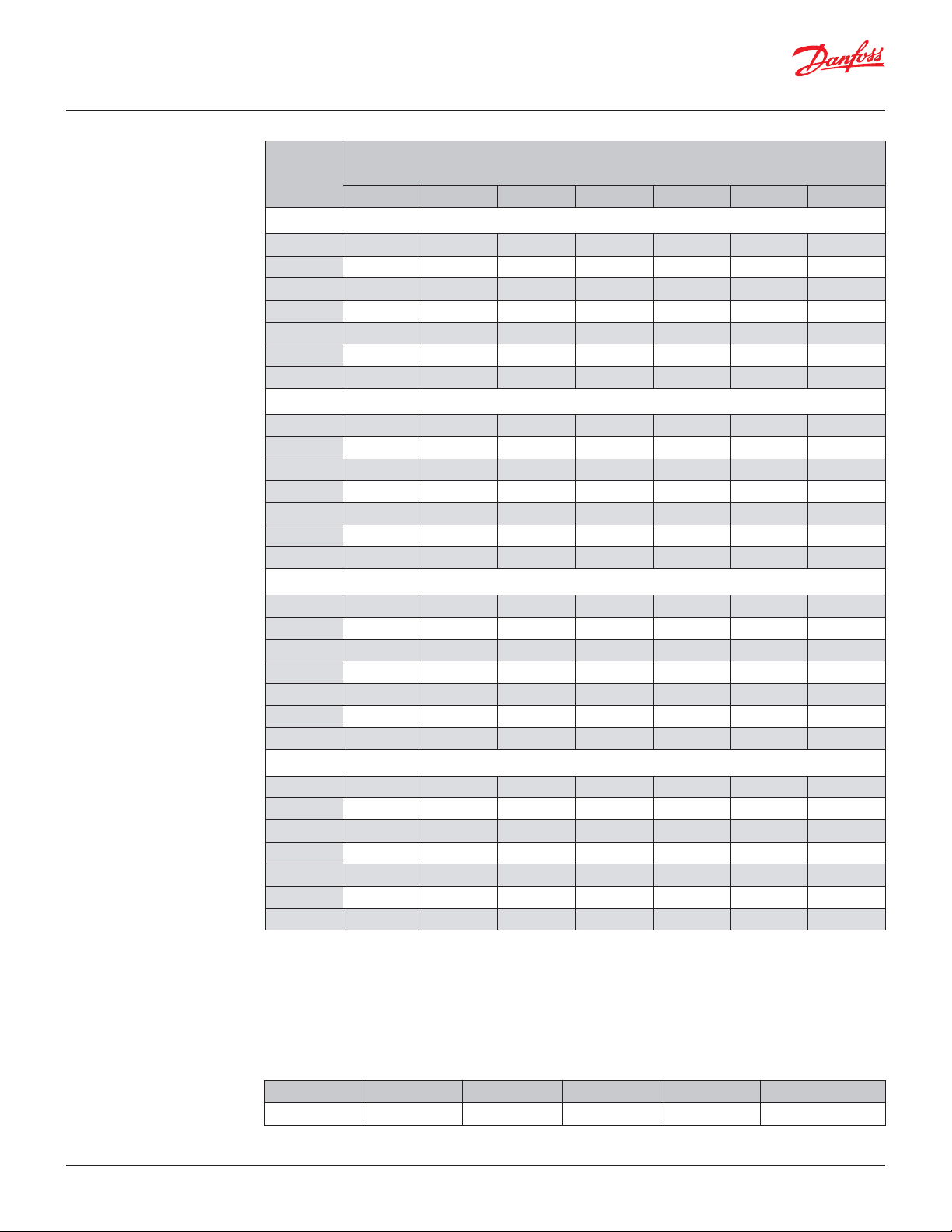
Capacity
Liquid capacity
Capacities are based on:
– liquid temperature
tl = 100 °F
– evaporating temperature
te = 40 °F
– superheat temperature
(te + 10 °F) = 50 °F
Metric conversions
1 psi = 0.07 bar
5
/9 (t1 °F - 32) = t2 °C
1 TR = 3.5 kW
Liquid capacity Qo [TR]
Typ e
1 2 3 4 5 6 7
at pressure drop across valve ∆p [bar]
R22/R407C
EVU 1
EVU 2 0.68 1.03 1.27 1.46 1. 63 1.79 1.93
EVU 3 1.02 1.55 1.90 2.19 2.45 2.69 2.90
EVU 4 1.69 2.59 3.17 3.66 4.09 4.48 4.84
EVU 5 2.20 3.36 4.12 4.75 5.31 5.83 6.29
EVU 6 2.71 4.14 5.07 5.85 6.54 7.17 7.74
EVU 8
0.34 0.52 0.64 0.73 0.82 0.85 0.97
3.39 5.18 6.34 7.31 8.18 8.96 9.68
R134A
EVU 1
EVU 2 0.68 0.96 1.18 1. 36 1. 52 1.67 1.80
EVU 3 1.02 1.45 1.77 2.05 2.29 2.51 2.71
EVU 4 1.71 2.41 2.59 3 .41 3.81 4.18 4.84
EVU 5
EVU 6 2.73 3.86 4.73 5.45 6.10 6.68 7. 22
EVU 8 3.41 4.83 5.91 6.81 7. 63 8.35 9.03
0.34 0.48 0.59 0.68 0.76 0.84 0.90
2.22 3 .13 3.84 4.43 4.96 5.43 5.86
R404A/507
EVU 1 0.25 0.36 0.44 0.51 0.57 0.62 0.67
EVU 2 0.50 0.71 0.87 1.01 1.13 1.23 1.33
EVU 3 0.76 1.07 1.31 1.51 1.69 1.85 2.00
EVU 4 1.26 1.78 2.18 2.52 2.81 3.09 3.33
EVU 5 1.64 2.31 2.83 3.27 3.66 4.01 4.33
EVU 6 2.02 2.85 3.49 4.03 4.50 4.94 5.33
EVU 8 2.53 3.56 4.36 5.04 5.63 6.18 6.66
R410a
EVU 1 0.34 0.52 0.64 0.73 0.82 0.90 0.97
EVU 2 0.68 1. 03 1.27 1. 46 1.63 1.79 1.93
EVU 3
EVU 4 1.69 2.59 3.17 3.66 4.07 4.48 4.84
EVU 5 2.20 3.36 4.12 4.75 5.29 5.83 6.29
EVU 6 2.71 4 .14 5.07 5.85 6. 51 7.17 7.74
EVU 8
1.02 1.55 1.90 2.19 2.44 2.69 2.90
3.39 5.18 6.34 7.31 8.14 8.96 9.68
© Danfoss | DCS (rja) | 2016.02
Correction factors
When liquid temperature tl ahead of the expansion
valve is other than 100°F, adjust the table capacities
by multiplying them by the appropriate correction
factor found in the following table.
Correction factors for liquid temperature t
tl [°F] 80 90 100 110 120
Factor 1.10 1.05 1.0 0 0.95 0.90
l
DKRCC.PD.BD0.1A.22 | 4
 Loading...