

Page 1

Data Sheet
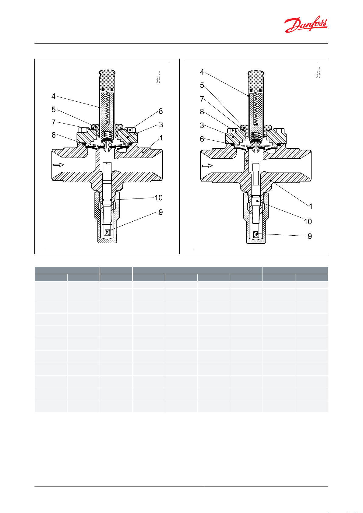
Solenoid valve
Type EVRS 3-20 and EVRST 10-20
Stainless steel solenoid valves used in liquid, suction, hot gas and oil return lines
EVRS and EVRST are valves made of stainless
steel.
• EVRS 3 is direct operated.
• EVRS 10, 15 and 20 are servo operated.
• EVRST 10,15 and 20 are forced servo
operated.
The valves are used in liquid, suction, hot gas
and oil return lines with ammonia or
uorinated refrigerants.
EVRS 3 and EVRST are designed for keeping
open at a pressure drop of 0 bar.
EVRS/EVRST 10, 15 and 20 are equipped with
spindel for manual opening.
EVRS and EVRST are supplied as components,
i.e. valve body and coil must be separately
ordered.
Features
• Stainless steel valve body and connections
• Max. working pressure 50 barg
• Applicable to HCFC, HFC, R717 (Ammonia)
and R744 (CO2)
• MOPD up to 38 bar with 20 watt a.c. coil
• Wide choice of a.c. and d.c. coils
• Designed for temperatures of media up to
105°C
• Manual stem on EVRS and EVRST 10, EVRST
15 and EVRST 20
• Classication: DNV, CRN, BV, EAC etc. To get
an updated list of certication on the
products please contact your local Danfoss
Sales Company.
72886419420en-000601
Page 2

Danfoss
32F418.11.15
37
36
4
16
28
49
51
18
29
Danfoss
32F417.11.15
24
4
16
18
28
49
29
Danfoss
32F419.13.13
28
14
8
6
16
45
5
EVRST EVRS
53
44
49
29
83
84
73
45
43
28
16
4
82
80
18
40
Pg13.5
20
36
Danfoss
32F476.11.12
4.
16.
18.
20.
24.
28.
29.
36.
40.
43.
44.
45.
49.
51.
53.
73.
80.
82.
83.
84.
Coil
Armature
Pilot valve plate
Earth terminal
Connection for exible steel
hose
Gasket
Pilot orice
DIN plug
Terminal box
Valve cover
O-ring
Valve cover gasket
Valve body
Cover
Manual operating spindle
Equalization hole
Diaphragm
Support washer
Valve seat
Main valve plate
Solenoid valve, Type EVRS 3-20 and EVRST 10-20
Function
Figure 1: EVRS 3, pipe thread
Figure 3: EVRS / EVRST 10 and 15
Figure 2: EVRS 3, weld
Figure 4: EVRS / EVRST 20
The solenoid valve design is based on three dierent principles:
1.
Direct operation
2.
Servo operation
3.
Forced servo operation
1. Direct operation
EVRS 3 is directly operated. The valve opens direct for full ow when the armature (16) moves up into the magnetic
eld of the coil. This means that the valve operates with a min. dierential pressure of 0 bar. The valve plate (18)
made of teon and is tted direct to the armature (16).
Inlet pressure acts from above on the armature and with it the valve plate. Thus, inlet pressure, spring force and the
weight of the armature act to close the valve when the coil is currentless.
2. Servo operation
© Danfoss | Climate Solutions | 2021.03 72886419420en-000601 | 2
Page 3

Solenoid valve, Type EVRS 3-20 and EVRST 10-20
EVRS 10, 15 and 20 are servo operated with a "oating" diaphragm (80). The pilot orice (29), which is of stainless
steel, is placed in the centre of the diaphragm. The teon pilot valve plate (18) is tted direct to the armature (16).
With the coil currentless, the main orice and pilot orice are closed. The pilot orice and main orice are held
closed by the weight of the armature, the armature spring force and the dierential pressure between inlet and
outlet sides.
When current is applied to the coil the armature is drawn up into the magnetic eld and opens the pilot orice. This
relieves the pressure above the diaphragm because the space above the diaphragm becomes connected to the
outlet side of the valve. The dierential pressure between inlet and outlet sides then presses the diaphragm away
from the main orice which opens to full ow. Thus a certain minimum dierential pressure is necessary to open the
valve and keep it open. For EVRS 10, 15 and 20 valves this dierential pressure is 0.05 bar. When current is switched
o, the pilot orice closes. Then the pressure above the diaphragm rises, via the equalization holes (73) in the
diaphragm, to the inlet pressure and causes the diaphragm to close the main orice.
3. Forced servo operation
EVRST 10, 15 and 20 are forced servo operated solenoid valves. Forced servo operation diers from servo operation
in that in a forced servo operated valve the armature and the diaphragm are connected by a spring. Thus the
armature helps to lift the diaphragm (80) and keep it lifted so that the pressure drop in the open valve is the least
possible. These types of valves therefore require no dierential pressure to keep them open.
© Danfoss | Climate Solutions | 2021.03 72886419420en-000601 | 3
Page 4

Solenoid valve, Type EVRS 3-20 and EVRST 10-20
Media
Refrigerants
Applicable to HCFC, HFC, R717 (Ammonia) and R744 (CO2).
New refrigerants
Danfoss products are continually evaluated for use with new refrigerants depending on market requirements.
When a refrigerant is approved for use by Danfoss, it is added to the relevant portfolio, and the R number of the
refrigerant (e.g. R513A) will be added to the technical data of the code number. Therefore, products for specic
refrigerants are best checked at store.danfoss.com/en/, or by contacting your local Danfoss representative.
© Danfoss | Climate Solutions | 2021.03 72886419420en-000601 | 4
Page 5

Type
Opening dierential pressure ∆p bar
kv value
(2)
m3/h
Max. working
pressure Ps
Min.
Max. (MOPD) liquid
(1)
10 W a.c.
12 W a.c.
20 W a.c.
20 W d.c.
EVRS 3
0.021253814
0.23
50 bar(g)
EVRS 10
0.0521253818
1.5
EVRST 10
0.014213816
1.5
EVRS 15
0.0521253818
2.7
EVRST 15
0.014213818
2.7
EVRS 20
0.0521253813
4.5
EVRST 20
0.014213813
4.5
Type
Rated capacity
(3)
kW
Liquid
Suction vapour
Hot gas
R717
R22
R134a
R404A
R410A
R717
R22
R134a
R404A
R410A
R717
R22
R134a
R404A
R410A
EVRS 3
21.8
4.6
4.3
3.2
4.5
6.5
2.1
1.7
1.7
2.3
EVRS/EVRST 10
142
30.2
27.8
21.1
29.793.4
2.5
3.1
4.3
42.6
13.91111.3
14.9
EVRS/EVRST 15
256
54.4
50.13853.5
16.1
6.2
4.4
5.5
7.7
76.7
24.9
19.8
20.3
26.7
EVRS/EVRST 20
426
90.6
83.5
63.3
89.1
26.9
10.3
7.3
9.212128
41.5
32.9
33.9
44.5
Type
R 744 Rated capacity kW
(4)
Liquid
Suction
EVRS 3
6.65
-
EVRS/ EVRST 10
43.3
6.9
EVRS/ EVRST 15
78
12.4
EVRS/ EVRST 20
130
20.7
Type
Liquid capacity Q
e
kW at pressure drop across valve ∆p bar
0.1
0.2
0.3
0.4
0.5
EVRS 3
17.8
25.1
30.8
35.6
39.8
EVRS/EVRST 10
116.0
164.0
201.0
232.0
259.0
EVRS/EVRST 15
209.0
295.0
362.0
418.0
467.0
EVRS/EVRST 20
348.0
492.0
603.0
696.0
778.0
Solenoid valve, Type EVRS 3-20 and EVRST 10-20
Product specication
Technical data
Temperature of medium
-40 °C / +105 °C for 10 or 12 watt coil. Max. 130 °C during defrosting. -40 °C / +80 °C for 20 watt coil.
Ambient temperature and enclosure for coil: See "Coils for solenoid valves", lit.no. AI237186440089
Table 1: Technical data
(1)
(1)
MOPD for media in gas form is approx. 1 bar greater.
MOPD for media in gas form is approx. 1 bar greater.
(2)
(2)
The kv value is the water ow in m3/h at a pressure drop in the valve of 1 bar, ρ = 1000 kg/m3.
The kv value is the water ow in m3/h at a pressure drop in the valve of 1 bar, ρ = 1000 kg/m3.
Table 2: Rated capacity
(3)
(3)
Rated liquid and suction vapour capacity is based on evaporating temperature te = -10 °C, liquid temperature ahead of valve tl = +25 °C, and
Rated liquid and suction vapour capacity is based on evaporating temperature te = -10 °C, liquid temperature ahead of valve tl = +25 °C, and
pressure drop across valve ∆p = 0.15 bar. Rated hot gas capacity is based on condensing temperature tc = +40 °C, pressure drop across valve ∆p
pressure drop across valve ∆p = 0.15 bar. Rated hot gas capacity is based on condensing temperature tc = +40 °C, pressure drop across valve ∆p
= 0.8 bar, hot gas temperature th = +60 °C, and subcooling of refrigerant ∆t
= 0.8 bar, hot gas temperature th = +60 °C, and subcooling of refrigerant ∆t
sub
sub
= 4 K.
= 4 K.
Table 3: Rated capacity
(4)
(4)
Rated liquid and suction vapour capacity is based on evaporating temperature te = -40 °C, liquid temperature ahead of the vale tl = - 8 °C and
Rated liquid and suction vapour capacity is based on evaporating temperature te = -40 °C, liquid temperature ahead of the vale tl = - 8 °C and
pressure drop across the valve ∆p = 0.15 bar For other condition please refer to DIR-Calc or contact your local Danfoss oce.
pressure drop across the valve ∆p = 0.15 bar For other condition please refer to DIR-Calc or contact your local Danfoss oce.
Capacity
Liquid capacity Ql kW
Table 4: R717 (NH3)
© Danfoss | Climate Solutions | 2021.03 72886419420en-000601 | 5
Page 6

Type
Liquid capacity Qe kW at pressure drop across valve ∆p bar
0.1
0.2
0.3
0.4
0.5
EVRS 3
3.8
5.3
6.6
7.6
8.5
EVRS/EVRST 10
24.7
34.9
42.7
49.3
55.1
EVRS/EVRST 15
44.4
62.8
76.9
88.8
99.2
EVRS/EVRST 20
73.9
105.0
128.0
148.0
165.0
Type
Liquid capacity Qe kW at pressure drop across valve ∆p bar
0.1
0.2
0.3
0.4
0.5
EVRS 3
3.5
4.9
6.0
7.0
7.8
EVRS/EVRST 10
22.7
32.2
39.4
45.5
50.8
EVRS/EVRST 15
40.9
57.9
70.9
81.8
91.5
EVRS/EVRST 20
68.2
96.5
118.0
136.0
153.0
Type
Liquid capacity Qe kW at pressure drop across valve ∆p bar
0.1
0.2
0.3
0.4
0.5
EVRS 3
2.6
3.7
4.6
5.3
5.9
EVRS/EVRST 10
17.2
24.3
29.8
34.4
38.5
EVRS/EVRST 15
31.0
43.8
53.7
62.0
69.3
EVRS/EVRST 20
51.7
73.0
89.5
103.0
116.0
Type
Liquid capacity Qe kW at pressure drop across valve ∆p bar
0.1
0.2
0.3
0.4
0.5
EVRS 3
3.7
5.3
6.4
7.5
8.3
EVRS/EVRST 10
24.3
34.44248.6
54.3
EVRS/EVRST 15
43.7
61.8
75.6
87.5
97.7
EVRS/EVRST 20
72.9
103
126
146
163
t
v
°C
-100+10
+20
+25
+30
+40
+50
R717 (NH
3
)
0.84
0.88
0.92
0.9711.03
1.09
1.16
R22, R134a
0.76
0.81
0.88
0.9611.05
1.16
1.31
R404A
0.7
0.76
0.84
0.9411.07
1.24
1.47
R410A
0.73
0.79
0.86
0.9511.06
1.23
1.47
Type
Pressure drop
across valve ∆p
bar
Suction vapour capacity Q
e
kW at evaporating temperature te °C
-40
-30
-20
-100+10
EVRS/EVRST 10
0.1
3.4
4.5
5.9
7.3
8.9
10.6
0.15
4.0
5.4
7.0
9.0
10.9
13.0
0.2
4.5
6.1
7.9
10.0
12.6
15.0
EVRS/EVRST 15
0.1
6.1
8.1
10.7
13.2
16.0
19.1
0.15
7.2
9.7
12.5
16.1
19.6
23.4
0.2
8.0
11.0
14.2
18.0
22.6
27.0
Solenoid valve, Type EVRS 3-20 and EVRST 10-20
Table 5: R22
Table 6: R134a
Table 7: R404A
Table 8: R410A
NOTE:
Capacities are based on liquid temperature tl = + 25 °C ahead of valve, evaporating temperature te = -10 °C, and
superheat 0 K.
Correction factors
When sizing valves, the table value must be multiplied by a correction factor depending on evaporating
temperature te.
Table 9: Correction factors
Suction vapour capacity Qe kW
Table 10: R717 (NH3)
© Danfoss | Climate Solutions | 2021.03 72886419420en-000601 | 6
Page 7

Type
Pressure drop
across valve ∆p
bar
Suction vapour capacity Qe kW at evaporating temperature te °C
-40
-30
-20
-100+10
EVRS/EVRST 20
0.1
10.2
13.5
17.8
21.9
26.6
31.9
0.15
12.1
16.1
20.9
26.9
32.6
39.0
0.2
13.4
18.3
23.7
29.9
37.7
45.1
Type
Pressure drop
across valve ∆p
bar
Suction vapour capacity Qe kW at evaporating temperature te °C
-40
-30
-20
-100+10
EVRS/EVRST 10
0.1
1.4
1.8
2.3
2.8
3.4
4.0
0.15
1.6
2.1
2.7
3.4
4.1
4.9
0.2
1.8
2.4
3.1
3.8
4.8
5.6
EVRS/EVRST 15
0.1
2.5
3.2
4.1
5.0
6.1
7.2
0.15
2.9
3.8
4.8
6.2
7.4
8.8
0.2
3.3
4.3
5.5
6.8
8.6
10.2
EVRS/EVRST 20
0.1
4.1
5.3
6.8
8.4
10.1
12.0
0.15
4.9
6.4
8.1
10.3
12.3
14.7
0.2
5.5
7.2
9.2
11.4
14.3
16.9
Type
Pressure drop
across valve ∆p
bar
Suction vapour capacity Qe kW at evaporating temperature te °C
-40
-30
-20
-100+10
EVRS/EVRST 10
0.1
0.87
1.2
1.6
2.1
2.6
3.2
0.15
0.99
1.4
1.9
2.4
3.2
3.9
0.2
1.1
1.6
2.1
2.8
3.5
4.5
EVRS/EVRST 15
0.1
1.6
2.1
2.8
3.8
4.7
5.7
0.15
1.8
2.5
3.4
4.4
5.7
7.0
0.2
2.0
2.8
3.8
5.0
6.3
8.1
EVRS/EVRST 20
0.1
2.6
3.6
4.7
6.3
7.8
9.6
0.15
3.0
4.2
5.6
7.3
9.5
11.7
0.2
3.3
4.7
6.4
8.3
10.5
13.5
Type
Pressure drop
across valve ∆p
bar
Suction vapour capacity Qe kW at evaporating temperature te °C
-40
-30
-20
-100+10
EVRS/EVRST 10
0.1
1.2
1.5
2.0
2.5
3.1
3.7
0.15
1.4
1.8
2.4
3.1
3.8
4.6
0.2
1.6
2.1
2.7
3.4
4.3
5.3
EVRS/EVRST 15
0.1
2.1
2.7
3.6
4.5
5.5
6.6
0.15
2.5
3.3
4.3
5.5
6.8
8.2
0.2
2.8
3.7
4.9
6.1
7.8
9.5
EVRS/EVRST 20
0.1
3.5
4.6
6.0
7.5
9.2
11.1
0.15
4.1
5.5
7.1
9.2
11.3
13.6
0.2
4.6
6.2
8.1
10.2
13.0
15.8
Type
Pressure drop
across valve ∆p
bar
Suction vapour capacity Qe kW at evaporating temperature te °C
-40
-30
-20
-100+10
EVRS/EVRST 10
0.1
1.9
2.3
2.9
3.5
4.2
5.0
0.15
2.2
2.9
3.5
4.3
5.1
6.1
0.2
2.6
3.3
4.0
5.0
5.9
7.0
EVRS/EVRST 15
0.1
3.3
4.2
5.2
6.3
7.6
9.0
0.15
4.0
5.1
6.3
7.7
9.2
11.0
0.2
4.7
5.9
7.3
8.9
10.7
12.7
EVRS/EVRST 20
0.1
5.6
7.0
8.6
10.5
12.6
15.0
0.15
6.7
8.6
10.5
12.9
15.4
18.4
0.2
7.8
9.9
12.2
14.9
17.8
21.2
Solenoid valve, Type EVRS 3-20 and EVRST 10-20
Table 11: R22
Table 12: R134a
Table 13: R404a
Table 14: R410A
© Danfoss | Climate Solutions | 2021.03 72886419420en-000601 | 7
Page 8

tv°C
-100+10
+20
+25
+30
+40
+50
R717 (NH3)
0.84
0.88
0.92
0.97
1.0
1.03
1.09
1.16
R22, R134a
0.76
0.81
0.88
0.96
1.0
1.05
1.16
1.31
R404A
0.70
0.76
0.84
0.94
1.0
1.07
1.24
1.47
R410A
0.76
0.80
0.89
0.96
1.0
1.05
1.18
1.37
Type
Pressure drop across
valve ∆p bar
Hot gas capacity Qh Kw
Evaporating temp. te = -10 °C. Hot gas temp. th = tc + 25 °C. Subcooling ∆t
sub
= 4 K
Condensing temperature tc °C
+20
+30
+40
+50
+60
EVRS 3
0.1
1.8
2.1
2.3
2.5
2.6
0.2
2.6
2.9
3.2
3.5
3.7
0.4
3.8
4.2
4.6
4.9
5.3
0.8
5.1
6.0
6.5
7.1
7.6
1.6
7.4
8.3
9.1
9.9
10.9
EVRS/EVRST 10
0.1
12.0
3.4
14.7
16.0
17.2
0.2
17.1
19.0
20.9
22.7
24.4
0.4
24.5
27.1
29.7
32.2
34.7
0.8
34.0
39.0
42.6
46.1
49.5
1.6
48.5
53.8
59.1
64.3
1.3
EVRS/EVRST 15
0.1
21.7
24.1
26.4
28.8
31.0
0.2
30.8
34.2
37.5
40.8
44.0
0.4
44.1
48.8
53.5
58.0
62.4
0.8
61.2
70.3
76.7
83.0
89.1
1.6
87.4
96.9
106.0
116.0
128.0
EVRS/EVRST 20
0.1
36.1
40.1
44.0
48.0
51.7
0.2
51.4
57.0
62.6
68.0
73.2
0.4
73.5
81.3
89.1
96.7
104.0
0.8
102.0
117.0
128.0
138.0
148.0
1.6
146.0
161.0
177.0
193.0
214.0
Type
Pressure drop across
valve ∆p bar
Hot gas capacity Qh Kw
Evaporating temp. te = -10 °C. Hot gas temp. th = tc + 25 °C. Subcooling ∆tsub = 4 K
Condensing temperature tc °C
+20
+30
+40
+50
+60
EVRS 3
0.1
0.68
0.72
0.76
0.78
0.79
0.2
0.97
1.0
1.1
1.1
1.1
0.4
1.4
1.5
1.5
1.6
1.6
0.8
1.9
2.0
2.1
2.3
2.3
1.6
2.7
2.9
3.0
3.1
3.2
Solenoid valve, Type EVRS 3-20 and EVRST 10-20
NOTE:
• Capacities are based on liquid temperature tl = +25 °C ahead of evaporator.
• The table values refer to the evaporator capacity and are given as a function of evaporating temperature te and
pressure drop ∆p in valve.
• Capacities are based on dry, saturated vapour ahead of valve. During operation with superheated vapour ahead of
valve, the capacities are reduced by 4% for each 10 K superheat.
Correction factors
When sizing valves, the evaporator capacity must be multiplied by a correction factor depending on liquid
temperature tl ahead of expansion valve.
When the corrected capacity is known, the selection can be made from the table.
Table 15: Correction factors
Table 16: R717 (NH3)
Table 17: R22
© Danfoss | Climate Solutions | 2021.03 72886419420en-000601 | 8
Page 9

Type
Pressure drop across
valve ∆p bar
Hot gas capacity Qh Kw
Evaporating temp. te = -10 °C. Hot gas temp. th = tc + 25 °C. Subcooling ∆tsub = 4 K
Condensing temperature tc °C
+20
+30
+40
+50
+60
EVRS/EVRST 10
0.1
4.4
4.7
4.9
5.1
5.2
0.2
6.3
6.7
7.0
7.2
7.3
0.4
9.0
9.6
10.0
10.3
10.4
0.8
12.4
13.2
13.9
14.7
14.9
1.6
17.5
18.6
19.6
20.2
20.5
EVRS/EVRST 15
0.1
8.0
8.5
8.9
9.2
9.3
0.2
11.4
12.1
12.6
13.0
13.2
0.4
16.3
17.2
18.0
18.5
18.7
0.8
22.3
23.1
24.9
26.5
26.8
1.6
31.5
33.5
35.2
36.4
36.9
EVRS/EVRST 20
0.1
13.3
14.1
14.8
15.3
15.5
0.21920.12121.7
22.0
0.4
27.1
28.73030.9
31.2
0.8
37.1
38.4
44.5
44.2
44.6
1.6
52.5
55.9
58.6
60.6
61.5
t
o
°C
-40
-30
-20
-100+10
R717 (NH
3
)
0.89
0.91
0.96
1.0
1.06
1.10
R22
0.90
0.94
0.97
1.0
1.03
1.05
Type
Pressure drop across
valve ∆p bar
Hot gas capacity Q
h
Kw
Evaporating temp. t
e
= -10 °C. Hot gas temp. ts = tc + 25 °C. Subcooling ∆t
sub
= 4 K
Condensing temperature t
c
°C
+20
+30
+40
+50
=60
EVRS 3
0.1
0.54
0.57
0.6
0.61
0.6
0.2
0.77
0.82
0.85
0.86
0.85
0.4
1.1
1.2
1.2
1.2
1.2
0.8
1.5
1.6
1.7
1.8
1.8
1.6
2.2
2.3
2.4
2.5
2.4
EVRS/EVRST 10
0.1
3.5
3.7
3.9
4.0
3.9
0.2
5.0
5.3
5.5
5.6
5.6
0.4
7.0
7.7
7.9
8.0
7.9
0.8
9.9
10.5
11.0
11.6
11.4
1.6
14.3
15.1
15.7
16.0
15.9
EVRS/EVRST 15
0.1
6.4
6.7
7.0
7.1
7.1
0.2
9.1
9.6
10.0
10.1
10.0
0.4
12.6
13.8
14.2
14.4
14.3
0.8
17.9
19.0
19.8
20.8
20.5
1.6
25.7
27.2
28.2
28.8
28.6
Solenoid valve, Type EVRS 3-20 and EVRST 10-20
NOTE:
• An increase in hot gas temperature th of 10 K reduces valve capacity approx. 2% and vice versa.
• A change in evaporating temperature te changes valve capacity; see correction factor table below.
Correction factors
When sizing valves, the table value must be multiplied by a correction factor depending on evaporating
temperature te.
Table 18: Correction factors
Hot gas capacity Qh kW
Table 19: R134a
© Danfoss | Climate Solutions | 2021.03 72886419420en-000601 | 9
Page 10

Type
Pressure drop across
valve ∆p bar
Hot gas capacity Qh Kw
Evaporating temp. te = -10 °C. Hot gas temp. ts = tc + 25 °C. Subcooling ∆t
sub
= 4 K
Condensing temperature tc °C
+20
+30
+40
+50
=60
EVRS/EVRST 20
0.1
10.6
11.2
11.7
11.8
11.8
0.2
15.1
16.0
16.6
16.8
16.7
0.4
21.0
22.9
23.7
24.0
23.8
0.8
29.8
31.6
33.0
34.7
34.2
1.6
42.8
45.3
47.1
47.9
47.6
Type
Pressure drop across
valve ∆p bar
Hot gas capacity Qh Kw
Evaporating temp. te = -10 °C. Hot gas temp. th = tc + 25 °C. Subcooling ∆tsub = 4 K
Condensing temperature tc °C
+20
+30
+40
+50
+60
EVRS 3
0.1
0.62
0.63
0.62
0.59
0.54
0.2
0.87
0.89
0.88
0.83
0.76
0.4
1.2
1.3
1.3
1.2
1.1
0.8
1.7
1.7
1.7
1.7
1.5
1.6
2.4
2.5
2.4
2.3
2.1
EVRS/EVRST 10
0.1
4.0
4.1
4.0
3.8
3.5
0.2
5.7
5.8
5.7
5.5
5.0
0.4
8.1
8.2
8.2
7.8
7.0
0.8
11.1
11.4
11.3
11.1
10.1
1.6
15.7
16.0
15.8
15.2
13.9
EVRS/EVRST 15
0.1
7.3
7.4
7.3
6.9
6.3
0.2
10.2
10.4
10.3
9.8
8.9
0.4
14.6
14.8
14.7
14.0
12.7
0.8
20.1
20.4
20.3
20.0
18.1
1.6
28.3
28.8
28.4
27.4
25.0
EVRS/EVRST 20
0.1
12.1
12.3
12.1
11.5
10.5
0.2
17.1
17.3
17.2
16.3
14.9
0.4
24.4
24.7
24.5
23.3
21.1
0.8
33.4
34.0
33.9
33.3
30.2
1.6
47.1
48.0
47.4
45.6
41.6
t
o
°C
-40
-30
-20
-100+10
R404A
0.86
0.88
0.9311.03
1.07
R134a
0.88
0.92
0.9811.04
1.08
Type
Pressure drop across
valve ∆p bar
Hot gas capacity Q
h
Kw
Evaporating temp. t
e
= -10 °C. Hot gas temp. th = tc + 25 °C. Subcooling ∆tsub = 4 K
Condensing temperature t
c
°C
+20
+30
+40
+50
+60
EVRS 3
0.1
0.8
0.8
0.8
0.8
0.7
0.2
1.1
1.1
1.1
1.110.4
1.6
1.6
1.6
1.6
1.5
0.8
2.2
2.7
2.2
2.2
2.1
1.6
3.1
3.2
3.2
3.2
2.9
Solenoid valve, Type EVRS 3-20 and EVRST 10-20
Table 20: R404A
NOTE:
An increase in hot gas temperature th of 10 K reduces valve capacity approx. 2% and vice versa.
A change in evaporating temperature te changes valve capacity; see correction factor table below.
Correction factors
When sizing valves, the table value must be multiplied by a correction factor depending on evaporating
temperature te.
Table 21: Correction factors
Table 22: R410A
© Danfoss | Climate Solutions | 2021.03 72886419420en-000601 | 10
Page 11

Type
Pressure drop across
valve ∆p bar
Hot gas capacity Qh Kw
Evaporating temp. te = -10 °C. Hot gas temp. th = tc + 25 °C. Subcooling ∆tsub = 4 K
Condensing temperature tc °C
+20
+30
+40
+50
+60
EVRS/EVRST 10
0.1
5.1
5.2
5.3
5.2
4.8
0.2
7.2
7.4
7.4
7.3
6.8
0.4
10.2
10.4
10.5
10.3
9.6
0.8
14.4
14.8
14.9
14.5
13.7
1.6
20.3
20.82120.5
19.1
EVRS/EVRST 15
0.1
9.2
9.4
9.4
9.3
8.6
0.21313.3
13.3
13.1
12.2
0.4
18.4
18.8
18.9
18.5
17.2
0.8
25.9
26.6
26.7
26.1
24.6
1.6
36.6
37.5
37.8
36.9
34.5
EVRS/EVRST 20
0.1
15.3
15.7
15.8
15.5
14.4
0.2
21.6
22.1
22.2
21.8
20.3
0.4
30.6
31.3
31.5
30.8
28.7
0.8
43.2
44.3
44.6
43.5411.66162.66361.6
57.4
t
o
°C
-40
-30
-20
-100+10
R410A
0.92
0.95
0.9811.02
1.03
Type
Hot gas
temperature
th °C
Condensing
temperature
tc °C
Hot gas capacity G
h
kg/s at pressure drop across valve ∆p bar
0.512345678
EVRS 3
90
25
0.003
0.005
0.006
0.007
0.007
0.007
0.007
0.007
0.007350.004
0.005
0.007
0.009
0.009
0.01
0.01
0.01
0.01450.005
0.006
0.009
0.01
0.011
0.012
0.013
0.013
0.013
EVRS/EVRST 10
25
0.022
0.03
0.04
0.045
0.048
0.048
0.048
0.048
0.048350.026
0.036
0.048
0.056
0.061
0.064
0.065
0.065
0.065450.03
0.041
0.056
0.066
0.074
0.079
0.083
0.085
0.086
EVRS/EVRST 15
25
0.04
0.054
0.072
0.081
0.086
0.087
0.087
0.087
0.087350.046
0.064
0.086
0.100
0.109
0.115
0.117
0.117
0.117450.053
0.074
0.101
0.120
0.133
0.142
0.149
0.153
0.155
EVRS/EVRST 20
25
0.066
0.09
0.12
0.12
0.144
0.145
0.145
0.145
0.145350.077
0.107
0.144
0.167
0.182
0.191
0.195
0.195
0.195450.089
0.124
0.169
0.199
0.211
0.237
0.248
0.255
0.258
Solenoid valve, Type EVRS 3-20 and EVRST 10-20
NOTE:
An increase in hot gas temperature th of 10 K reduces valve capacity approx. 2% and vice versa.
A change in evaporating temperature te changes valve capacity; see correction factor table below.
Correction factors
When sizing valves, the table value must be multiplied by a correction factor depending on evaporating
temperature te.
Table 23: Correction factors
Table 24: R717 (NH3)
© Danfoss | Climate Solutions | 2021.03 72886419420en-000601 | 11
Page 12
Type
Hot gas
temperature
th °C
Condensing
temperature
tc °C
Hot gas capacity Gh kg/s at pressure drop across valve ∆p bar
0.512345678
EVRS 3
90
25
0.008
0.011
0.014
0.016
0.017
0.017
0.017
0.017
0.017350.009
0.012
0.017
0.019
0.021
0.022
0.022
0.022
0.022450.01
0.014
0.019
0.022
0.025
0.026
0.027
0.028
0.028
EVRS/EVRST 10
25
0.051
0.069
0.092
0.104
0.109
0.111
0.111
0.111
0.111350.058
0.08
0.108
0.125
0.136
0.142
0.144
0.144
0.144450.066
0.092
0.125
0.146
0.162
0.172
0.179
0.183
0.183
EVRS/EVRST 15
25
0.091
0.125
0.165
0.187
0.197
0.199
0.199
0.199
0.199350.105
0.144
0.194
0.225
0.244
0.256
0.258
0.258
0.258450.119
0.165
0.224
0.263
0.291
0.31
0.322
0.329
0.33
EVRS/EVRST 20
25
0.152
0.208
0.275
0.311
0.328
0.332
0.332
0.332
0.332350.174
0.241
0.323
0.375
0.407
0.425
0.431
0.431
0.431450.193
0.275
0.374
0.439
0.485
0.516
0.537
0.548
0.55
Type
Hot gas
temperature
th °C
Condensing
temperature
tc °C
Hot gas capacity Gh kg/s at pressure drop across valve ∆p bar
0.512345678
EVRS 3
60
25
0.007
0.009
0.011
0.012
0.012350.009
0.011
0.014
0.016
0.016
0.016
0.016450.01
0.012
0.018
0.02
0.021
0.021
0.021
0.021
0.021
EVRS/EVRST 10
25
0.048
0.06
0.074
0.077
0.077350.055
0.071
0.092
0.103
0.104
0.104450.06
0.084
0.111
0.127
0.134
0.135
0.135
0.135
0.135
EVRS/EVRST 15
25
0.081
0.108
0.134
0.14
0.14350.094
0.129
0.166
0.192
0.187
0.187
0.187450.108
0.151
0.2
0.228
0.241
0.244
0.244
0.244
0.244
EVRS/EVRST 20
25
0.134
0.18
0.223
0.233
0.233350.157
0.215
0.276
0.307
0.312
0.312
0.312450.181
0.252
0.333
0.381
0.403
0.407
0.407
0.407
0.407
Type
Hot gas
temperature
th °C
Condensing
temperature
tc °C
Hot gas capacity Gh kg/s at pressure drop across valve ∆p bar
0.512345678
EVRS 3
60
25
0.01
0.013
0.018
0.021
0.022
0.023
0.023
0.023
0.023350.011
0.015
0.02
0.024
0.027
0.028
0.029
0.029
0.03450.012
0.017
0.023
0.028
0.032
0.034
0.035
0.036
0.037
EVRS/EVRST 10
25
0.063
0.087
0.116
0.134
0.145
0.148
0.149
0.149
0.149350.072
0.1
0.134
0.158
0.174
0.184
0.19
0.19
0.192450.081
0.112
0.153
0.182
0.203
0.228
0.228
0.237
0.239
EVRS/EVRST 15
25
0.113
0.157
0.21
0.242
0.26
0.267
0.269
0.269
0.269350.129
0.18
0.242
0.285
0.313
0.332
0.341
0.342
0.346450.146
0.202
0.275
0.327
0.365
0.393
0.411
0.424
0.431
EVRS/EVRST 20
25
0.189
0.262
0.350
0.403
0.433
0.445
0.449
0.449
0.449350.215
0.300
0.404
0.474
0.521
0.552
0.569
0.57
0.576450.243
0.337
0.459
0.545
0.609
0.656
0.684
0.707
0.719
Solenoid valve, Type EVRS 3-20 and EVRST 10-20
Table 25: R22
Table 26: R134a
Table 27: R404A
© Danfoss | Climate Solutions | 2021.03 72886419420en-000601 | 12
Page 13

Danfoss
A32F668.10.10
4
5
7
1
Danfoss
A32F670.10.10
Type
Hot gas
temperature
th °C
Condensing
temperature
tc °C
Hot gas capacity Gh kg/s at pressure drop across valve ∆p bar
0.512345678
EVRS 3
90
25
0.009
0.013
0.018
0.022
0.025
0.028
0.031
0.031
0.031350.01
0.014
0.02
0.025
0.029
0.032
0.035
0.038
0.038450.012
0.016
0.023
0.029
0.033
0.037
0.04
0.044
0.047
EVRS/EVRST 10
25
0.059
0.083
0.117
0.144
0.166
0.185
0.201
0.201
0.201350.067
0.094
0.133
0.163
0.189
0.211
0.231
0.249
0.249450.076
0.108
0.152
0.186
0.215
0.241
0.263
0.285
0.304
EVRS/EVRST 15
25
0.106
0.15
0.211
0.259
0.3
0.334
0.361
0.361
0.361350.12
0.17
0.24
0.294
0.34
0.38
0.416
0.449
0.449450.137
0.194
0.274
0.335
0.387
0.433
0.474
0.513
0.548
EVRS/EVRST 20
25
0.177
0.149
0.352
0.431
0.498
0.556
0.602
0.602
0.602350.2
0.283
0.4
0.49
0.566
0.633
0.693
0.748
0.748450.228
0.323
0.456
0.558
0.645
0.722
0.79
0.854
0.913
Solenoid valve, Type EVRS 3-20 and EVRST 10-20
Table 28: R410A
NOTE:
An increase in hot gas temperature th of 10 K reduces valve capacity approx. 2% and vice versa.
Material specication
Figure 5: EVRS 3, Pipe thread
Figure 6: EVRS 3, welded
© Danfoss | Climate Solutions | 2021.03 72886419420en-000601 | 13
Page 14
Danfoss
A32F669.10.10
Danfoss
A32F671.10.10
Solenoid valves
Standard
No.
Description
Type
Material
Analysis
Mat.no.
W.no.
DIN
EN
1
Valve housing
EVRS 3
Stainless steel
X8 CrNiS 18-9
1.4305
10088
EVRS (T )
10/15/20
Stainless steel
X6 CrNi 18-9
1.4308
17455
2
Welding tube
EVRS 3
Stainless steel
X2 CrNiMo
17-12-2
1.4404
174553Cover
EVRS (T )
10(15/20
Stainless steel
X6 CrNi 18-9
1.4308
17455
4
Armature tube
EVRS(T )
3/10/15/20
Stainless steel
X2 CrNi 19-11
1.4306
10088
5
Armature tube
nut
EVRS(T )
3/10/15/20
Stainless steel
X8 CrNi 19-11
1.4305
100886Gasket
EVRS(T )
3/10/15/20
RubberCr7
Gasket armature
tube
EVRS(T )
10/15/20
Al gasket
Al 99.5
3.0255
102108Screws
EVRS(T )
10/15/20
Stainless steel
A2-70
3506
9
Spindle for man.
oper.
EVRS(T )
10/15/20
Stainless steel
X8 CrNiS 18-9
1.4305
1008810Gasket
EVRS(T )
10/15/20
Rubber
Cr
Solenoid valve, Type EVRS 3-20 and EVRST 10-20
Figure 7: EVRS/ EVRST 10 and 15
Figure 8: EVRS/ EVRST 20
Table 29: Material specication
© Danfoss | Climate Solutions | 2021.03 72886419420en-000601 | 14
Page 15

Danfoss
A32F414.11
Danfoss
A32F415.11
Danfoss
A32F416.11
Danfoss
A32F474.11
Type
L
5
max.
Weight with coil
10 W
12 W
20 W
mmmmkg
EVRS 3, pipe thread
75850.7
EVRS 3, weld
75850.6
EVRS/EVRST 10
75851.2
EVRS/EVRST 15
75851.3
EVRS/EVRST 20
75852
Solenoid valve, Type EVRS 3-20 and EVRST 10-20
Dimensions and weights
Figure 9: EVRS 3, pipe thread
Figure 10: EVRS 3, weld
Figure 12: Coil with DIN plugs Figure 13: EVRS / EVRST 10 and 15
Coil with terminal box
Figure 11: Coil with cable
Figure 14: EVRS / EVRST 20 Coil with
terminal box
NOTE:
Weight of coil:
• 10 W: approx. 0.3 kg
• 12 and 20 W: approx. 0.5 kg
Table 30: Weight of coil
© Danfoss | Climate Solutions | 2021.03 72886419420en-000601 | 15
Page 16

Solenoid valve, Type EVRS 3-20 and EVRST 10-20
NOTE:
Above weight is approximated.
© Danfoss | Climate Solutions | 2021.03 72886419420en-000601 | 16
Page 17

Type
Max. working pressure
Ps bar
Connection
Code no.
Weld in.
Pipe thread ISO 228/1
With manual stem
Without manual stem
EVRS 3
50
3
⁄8
032F3080
EVRS 350G 1/4
032F3081
EVRS 10
50
1
⁄2
032F3082
EVRST 10
50
1
⁄2
032F3083
EVRS 15
50
3
⁄4
032F3084
EVRST 15
50
3
⁄4
032F3085
EVRS 20501
032F5437
EVRST 20501
032F5438
Solenoid valve, Type EVRS 3-20 and EVRST 10-20
Ordering
Figure 15: Ordering
Table 31: Separate valve bodies
Coils See "Coils for solenoid valves", data sheet. AI237186440089
© Danfoss | Climate Solutions | 2021.03 72886419420en-000601 | 17
Page 18

File name
Document type
Document topic
Approval authority
0C14029.523467890YTN
Pressure - Safety Certicate
CRN
TSSA
Solenoid valve, Type EVRS 3-20 and EVRST 10-20
Certicates, declarations and approvals
The list contains all certicates, declarations, and approvals for this product type. Individual code number may have
some or all of these approvals, and certain local approvals may not appear on the list.
Some approvals may change over time. You can check the most current status at danfoss.com or contact your local
Danfoss representative if you have any questions.
Table 32: Valid approvals
© Danfoss | Climate Solutions | 2021.03 72886419420en-000601 | 18
Page 19

Online support
Danfoss oers a wide range of support along with our products, including digital product information, software,
mobile apps, and expert guidance. See the possibilities below.
The Danfoss Product Store
The Danfoss Product Store is your one-stop shop for everything product related—no matter where
you are in the world or what area of the cooling industry you work in. Get quick access to essential
information like product specs, code numbers, technical documentation, certications, accessories,
and more.
Start browsing at store.danfoss.com.
Find technical documentation
Find the technical documentation you need to get your project up and running. Get direct access to
our ocial collection of data sheets, certicates and declarations, manuals and guides, 3D models
and drawings, case stories, brochures, and much more.
Start searching now at www.danfoss.com/en/service-and-support/documentation.
Danfoss Learning
Danfoss Learning is a free online learning platform. It features courses and materials specically
designed to help engineers, installers, service technicians, and wholesalers better understand the
products, applications, industry topics, and trends that will help you do your job better.
Create your Danfoss Learning account for free at www.danfoss.com/en/service-and-support/learning.
Get local information and support
Local Danfoss websites are the main sources for help and information about our company and
products. Find product availability, get the latest regional news, or connect with a nearby expert—all
in your own language.
Find your local Danfoss website here: www.danfoss.com/en/choose-region.
Spare Parts
Get access to the Danfoss spare parts and service kit catalog right from your smartphone. The app
contains a wide range of components for air conditioning and refrigeration applications, such as
valves, strainers, pressure switches, and sensors.
Download the Spare Parts app for free at www.danfoss.com/en/service-and-support/downloads.
Coolselector®2 - nd the best components for you HVAC/R system
Coolselector®2 makes it easy for engineers, consultants, and designers to nd and order the best
components for refrigeration and air conditioning systems. Run calculations based on your operating
conditions and then choose the best setup for your system design.
Download Coolselector®2 for free at coolselector.danfoss.com.
Danfoss can accept no responsibility for possible errors in catalogues, brochures and other printed material. Danfoss reserves the right to alter its
products without notice. This also applies to products already on order provided that such alterations can be made without subsequential
changes being necessary in specications already agreed. All trademarks in this material are property of the respective companies. Danfoss and
the Danfoss logotype are trademarks of Danfoss A/S. All rights reserved.
© Danfoss | Climate Solutions | 2021.03 72886419420en-000601 | 19
 Loading...