

Page 1
Datasheet
ESBE VTC 511
3-Way Thermic Valve
Applications:
Typical Applications:
• High mass non-condensing boiler coupled
with low return water situations, i.e. snow
melt systems or high mass concrete
radiant floor heating
• Gravity hot water conversion systems
• Solid fuel boilers feeding storage tanks or
a heating system
• Solar heating and stratification control for
storage tank
The ESBE VTC thermic valve is a thermostatic
by-pass valve which regulates the
temperature of either the supply out or the
return of water in a hydronic heating system.
In a conventional application, the VTC valve
safeguards non-condensing boilers against
corrosion from condensation that would
result if a minimum flue gas temperature
is not maintained. With the VTC the boiler
is able to recover and keep up with the
drop in water temperature. The VTC valve
can also be used on a solid fuel boiler or
a solar application where a minimum or
maximum water temperature is trying to be
maintained.
Features:
• Thermostatically maintains a high and steady
return temperature increasing the life and
efficiency of the heat source
• Protection from thermal shock within non-
condensing boilers
• Self contained thermostatic element with no
adjustment required
• Interchangeable thermostat elements, to
meet temperature requirements
• Low leakage rate through the ports of
the valve
Ordering Information:
AI000086403224
* Valve body and thermostat sold separately. Order one valve body and
VTC Valve Body, Without Thermostat*
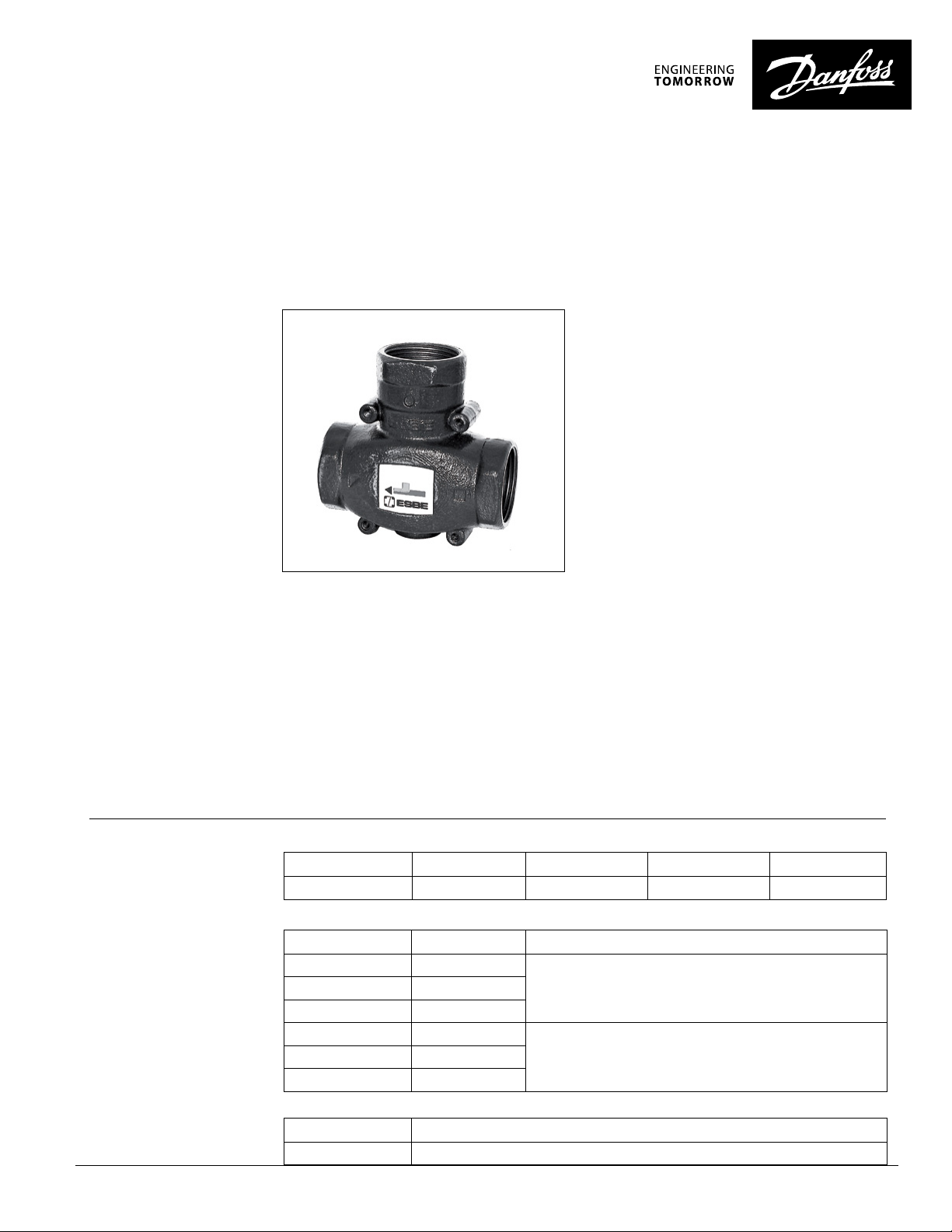
Code No. Series Cv Valve Size
193 B1701 V TC511 16.2 1-1¼” FNPT
Internal VTC Temperature Element
Code No. Series Typical Application
193 B1702 122 °F (50°C)
193 B170 4 140 °F (60°C)
193 B1709 149 °F (65°C)
193 B170 6 176 °F (80°C)
Spare Parts
Code No. Description
98060150 O-ring for brass plug
one temperature element to assemble a complete valve
Return line boiler protection193 B1703 131°F (55°C)
Boiler outlet, storage tank feed193 B1705 158 °F (70°C)
Connection
© Danfoss | 02/2022 | 1
Page 2
ESBE VTC 511 3-Way Thermic Valve Datasheet
ESBE VTC 511 3-Way Thermic Valve Datasheet
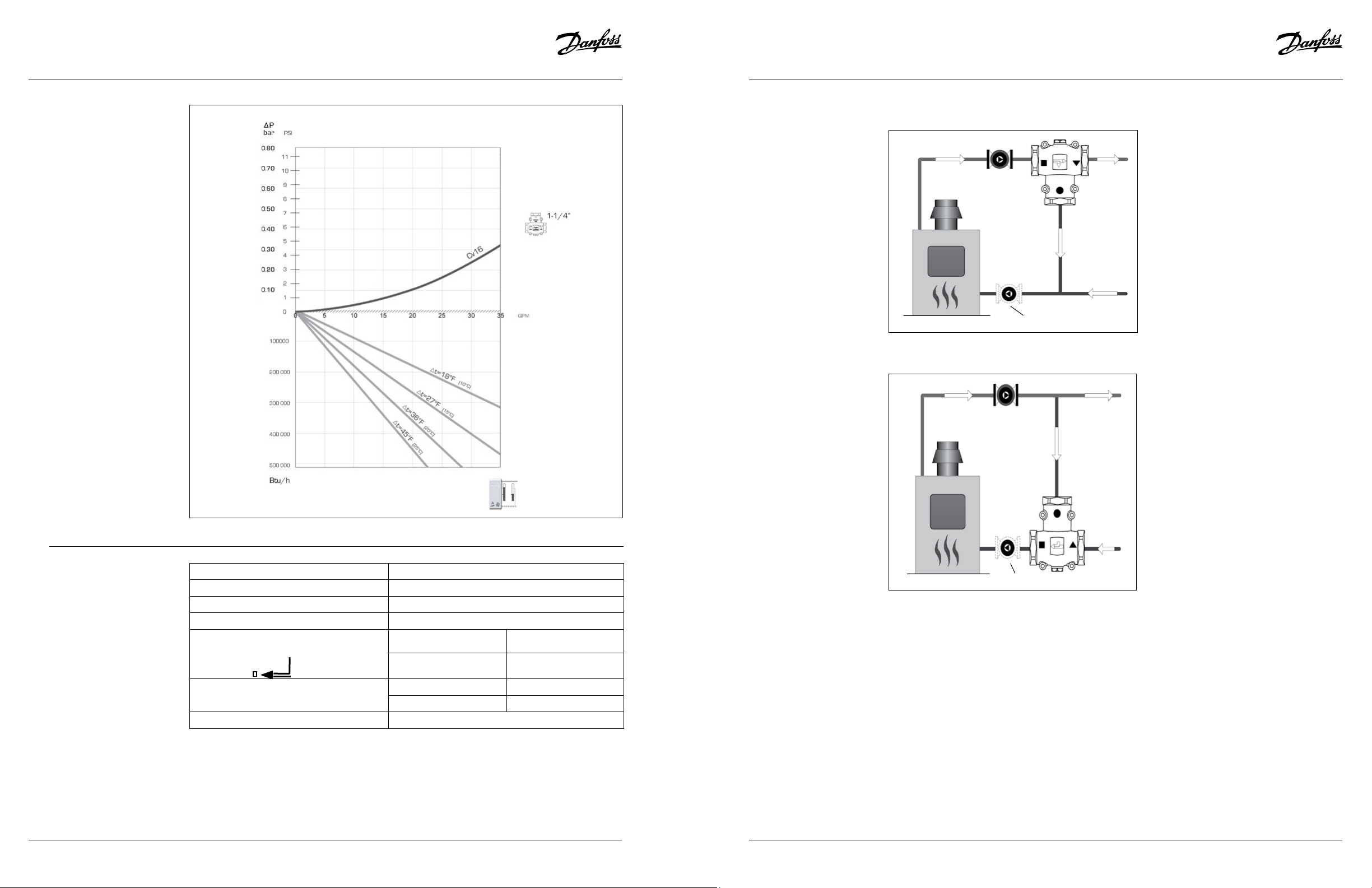
Valve Selection:
Piping Orientation:
Supply Mounted
(149 °F (65°C), 158°F (70°C), 167°F (75°C) elements)
Circulator
VTC valve
Other location for circulator
Return Mounted
(122 °F (50°C), 131°F (55°C), 140°F (60°C) elements)
Circulator
When the VTC is piped on the supply
side out from the heat source, the valve
will begin to allow water out to the
system when the temperature of the fluid
meets the temperature of the inserted
thermostat element.
The VTC valve, when placed on the return
side will open when the minimum return
temperature of the element is reached.
When the fluid temperature reaches
18°F (10°C) higher than the element’s
temperature, the return port from the
system will be fully open.
Technical Specifications:
Max. system pressure 145psi (10 bar)
Max. medium temperature 230°F (110 °C)
Min. medium temperature 32°F (0°C)
Fully open temperature differential 18°F (10°C) higher than temperature element
Max. differential pressure across:
B - AB & A - AB 14.5psi (1 bar)
B (О)
AB( )
Max. leakage rate
A(∆)
B - A 4.35psi (0.35 bar)
A - AB 1% of Cv
B - AB 3% of Cv
Allowable medium Closed loop system, Glycol mixture up to 50%
VTC
valve
Other location for circulator
2 | © Danfoss | 02/2022
AI000086403224
AI000086403224
© Danfoss | 02/2022 | 3
Page 3

ESBE VTC 511 3-Way Thermic Valve Datasheet
Systems Applications:
VTC Thermic Valve on Gravity Conversion System
Because gravity conversion systems contain
an enormous volume of water, the water
returning to the heat source could be
significantly cooler, leading to condensation
and a shorter life for the heat source.
Adding a thermic valve to the system will
prevent the boiler from sustained operation
at temperatures below the dew point of
their flue gases.
VTC Valve
VTC Valve on Multi-zone Systems with Circulators
Where a high mass non condensing
heat source is matched with a large low
temperature system, a situation could occur
where the heat source is unable to keep up
with the rate of demand from the system.
The use of the thermic valve provides the
opportunity for the heat source to catch-up.
VTC Valve
Charging of Storage Tank through Solar Heating
With the thermic VTC valve, an efficient
method of charging a tank can be done.
To achieve efficiency through the solar
panel, cool water should enter allowing
for a higher differential temperature across
the panel. Additionally heated fluid from
the panel should be properly distributed
within the tank to reduce stratification i.e.
even temperature distribution, within the
tank.
4 | © Danfoss | 02/2022
AI000086403224
Page 4

Dimensions:
A B C Depth Weight
Size in (mm) in (mm) in (mm) in (mm) lbs (kg)
1-¼” 4.13 (105) 1.50 (38) 2.95 (75) 2.17 (55) 3.04 (1.38)
Construction:
Valve body Nodular iron
O-ring EPDM
Thermostat cover Brass
Thermostat Copper
Any information, including, but not limited to information on selection of product, its application or use, product design, weight, dimensions, capacity or any other technical data in product manuals, catalogues descriptions, advertisements, etc.
and whether made available in writing, orally, electronically, online or via download, shall be considered informative, and is only binding if and to the extent, explicit reference is made in a quotation or order confirmation. Danfoss cannot accept any
responsibility for possible errors in catalogues, brochures, videos and other material. Danfoss reserves the right to alter its products without notice. This also applies to products ordered but not delivered provided that such alterations can be made without
5 | © Danfoss | 02/2022
changes to form, fit or function of the product. All trademarks in this material are property of Danfoss A/S or Danfoss group companies. Danfoss and the Danfoss logo are trademarks of Danfoss A/S. All rights reserved.
AI000086403224
 Loading...