

Page 1

ESBE VTA Series Lead-Free Thermostatic Mixing Valves Datasheet
Keep water temperatures safe in point
of source applications with thermostatic
mixing valves.
Low maintenance, easy-to-install thermostatic mixing valves
(TMV) are designed to protect against accidental scalding, &
increase amounts of available hot water.
HIGH
Temperatures within
source reduce growth
of Legionella while
safeguarding against
scalding.
heating.danfoss.us
Page 2
ESBE VTA Series Lead Free Thermostatic Mixing Valves Datasheet
Applications:
Specifications:
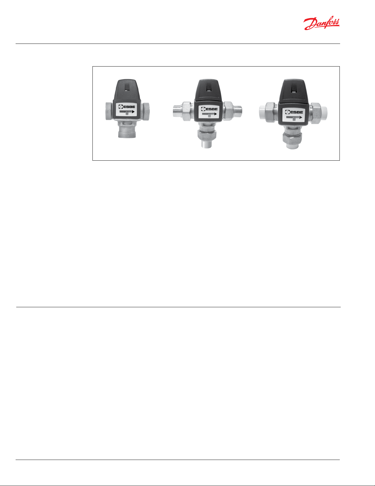
The compact ESBE VTA series are lead-free (LF)
thermostatic mixing valves (TMV) designed for
point of source in domestic hot water distribution
systems and/or regulation of supply in hydronic
heating systems. The series of LF valves meet
the NSF/ANSI 372 standards for ‘lead free’
requirements.
The VTA series of valve replaces the legacy 20
Series and 30MR Series of valves. The VTA Series
are available in four temperature ranges:
• 85 to 120°F (30 to 49°C) (Domestic/ Hydronic)
• 95 to 140°F (35 to 60°C) (Domestic/ Hydronic)
• 70 to 110°F (20 to 45°C) (Hydronic)
• 85 to 160°F (30 to 70°C) (Hydronic)
As a point of source for domestic hot water
application, the thermostatic control within
the VTA valve accommodates increased water
• Conforms to ASSE-1017*
* Ranges 85°-120° F & 95°-140° F only
• Anti-scald function
• Designed for mixing purposes
• Long life and easy maintenance
• Quiet operation
• Compact design and lightweight snap-
on cover for dirt protection and to prevent
unauthorized adjustment or tampering
• Cover label for recording setting
information including recorded outlet
temperature and date installed
• Available connections:
• Threaded body (FNPT)
• Solder (Union connection)
• CPVC (Union connection)
• Maximum working pressure:
150 psi (10 bar) / CPVC: 80 psi (5.5 bar)
temperature at the source while maintaining
appropriate water temperatures out to the
fixtures. With a higher temperature at the source,
the installation benefits of the VTA series include:
• Additional volume of domestic hot water
to the fixtures at an appropriate regulated
temperature
• Preventative measures to reduce
growth of Legionella by maintaining a
high temperature within the source &
safeguarding against scalding down stream
In the event there is a cold-water supply failure,
the hot water supply closes automatically.
The angle flow pattern of the ESBE VTA series
tmvs combine high quality performance with
remarkable ease of installation and servicing.
• Maximum differential pressure between hot
and cold ports:
44 psi (3 bar)
• Maximum system differential pressure
between outlet and inlet ports:
72 psi (5 bar)
• Maximum hot water inlet temperature:
19 4°F (90°C)
• Minimum required flow for proper
temperature regulation:
• All valves except 1” NPT: 0.9 GPM
• 1“ NPT valve size: 2.0 GPM
• Up to a 50% glycol mixture for closed loop
hydronic system
2 | © Danfoss | 03/2020
AI189286403251
Page 3
ESBE VTA Series Lead Free Thermostatic Mixing Valves Datasheet
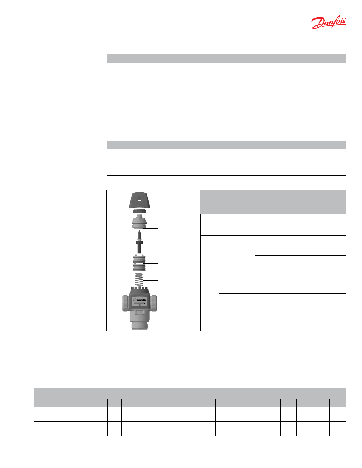
Ordering
Information:
Valve Connection Type Valve Size Temperature Range Cv Code No.
¾” 70° t o 110 °F (20° to 45°C) 1.9 065B8868LF
¾” 85° to 120°F (30° to 49°C) 1.9 065B8869LF
Female NPT
¾” 95° to 140 °F (35° to 60°C) 1.9 065B8870LF
¾” 85° to 160°F (30° to 70°C) 1.9 065B8871LF
1” 85° to 120°F (30° to 49°C) 4.1 3162 2111LF
1” 95° to 140°F (35° to 60°C) 4.1 31622011LF
85° to 120°F (30° to 49°C) 1.9 065B8877LF
Union Solder & CPVC
(Requires tailpiece kits, sold seperately. See below.)
-
95° to 140 °F (35° to 60°C) 1.9 065B8878LF
85° to 160°F (30° to 70°C) 1.9 065B8872LF
Accessories Size Description Code No.
½” solder tailpieces 065B8901
Tailpiece Kits
(for Sold er & CPVC)
¾” solder tailpieces 065B8892
¾” CPVC
(follow pipe manufacturers instructions) 065B8898
Spare Parts
1- Cap
Item
No.
Description Temperature Range Code No.
Cap for All
2- Adjustment
Bonnet
1
Except
-
1” NPT
065B8846
3- Thermostat
70° to 110°F (20° to 45°C)
065B8842
Repair Kit for
4- Shuttle
All Except
85° to 120°F (30° to 49°C)
065B8843
1” NPT
5- Spring
6- Body
1-5
Repair Kit for
95° to 140°F (35° to 60°C)
85° to 120°F (30° to 49°C)
065B8844
37101600
1” NPT
Temperature
Setting:
95° to 140°F (35° to 60°C)
VTA series of tmvs will provide a mixed water temperature according to the following table. The outlet
temp. stated are approximate, based on the given hot water supply temp. & a cold water supply of 50°F
3710140 0
(10°C). For other cold water temp. correct the outlet temp. by 1°F for every 10°F (or 1°C for every 10°C)
deviation from 50°F (10°C), up or down.
Hot Water
Tem p.
120 °F (49°C) 67(19) 74(2 3) 81(27 ) 87(31) 94(3 4) 109(43) 8 0(27) 90(32) 97(36) 102(39) 107(42 ) 115( 46 ) 95(35) 10 6(41) 115( 46 ) 11 9(4 8) 120(49) 120(49)
140 °F (60°C) 68 (20) 75( 24) 82(28) 90(32) 97(36) 113(45) 81(27 ) 91(3 3) 9 9(37) 104 (40) 109(43) 117(4 7) 97(36) 108 (42) 117 (47 ) 126(52) 133(56) 140 (60)
160° F (70°C) 69( 21) 76( 24) 8 4(29) 92(33) 100 (38) 118 (4 8) 82(28) 93(34) 100(3 8) 10 6(41) 112( 44) 118 (48 ) 9 9(37) 109 (43) 118 (48 ) 127(53) 135(57) 14 5(63)
180° F (82°C) 70( 21) 77(25) 86(30) 95( 35) 102(39) 12 2(50 ) 82(28) 95(35) 102(39) 10 8(42) 11 4(4 6) 120(49) 100( 38) 111(4 4) 120(49) 12 9(5 4) 13 6(5 8) 149 (65)
70° - 110°F (20° to 45°C) 85°- 120 °F (30°- 49°C) 95°- 140 °F (35° - 60°C)
1 2 3 4 5 6 1 2 3 4 5 6 1 2 3 4 5 6
AI189286403251
© Danfoss | 03/2020 | 3
Page 4

ESBE VTA Series Lead Free Thermostatic Mixing Valves Datasheet
Flow Pattern &
Capacity:
Hot (DHW) / Supply (Hydronic)
Cold (DHW) / Return (Hydronic)
Flow vs. Pressure Drop for VTA Series
Mixed
Pattern:
The VTA series provides a mixing
flow pattern for both a domestic
hot water (DHW) application and
for hydronic heating systems. If a
diverting flow pattern is required
refer to the VTA572 datasheet
located on heating.danfoss.us
(Code No.31700200).
1” NPT
Cv 4 .1
All others
Cv 1.9
Capacity:
The flow rate through the VTA
series valve at any given pressure
drop can be determined from the
capacity diagram.
4 | © Danfoss | 03/2020
AI189286403251
Page 5

ESBE VTA Series Lead Free Thermostatic Mixing Valves Datasheet
Domestic Hot Water
Sizing:
For domestic hot water systems the VTA series
can be sized based on the number of fixture
units the valve will supply.
Valve selection process:
1. Determine the type and number of fixtures
to be supplied by the mixing valve.
2. Assign fixture units from Table 1 for each
fixture type.
3. Add the total number of fixture units.
4. Confirm the mixing valve has sufficient
capacity from Table 2.
Example:
A residential home with 2-1/2 baths (3 bathroom
sinks and 2 baths or 7 fixture units), kitchen
(1 kitchen sink and a dish washer or 3 fixture
units), and a clothes washer (2 fixture units).
Hot water supply from the water heater is ¾”.
The total is 12 fixture units.
Table 1. Fixture Units
Bathroom sink 1
Kitchen Sink 2
Bath 2
Shower 2
Clothes Washer 2
Dish Washer 1
Table 2. VTA Series Capacity
Valve Size Max. Fixture Units
All except 1” NPT 16
1” NPT 30
Note: Cer tain fixtures such as hot tubs, roman tubs or spa
showers may require a high volume of hot water. The V TA
series may not be capable of providing sufficient hot water to
these fixtures.
Typical Piping:
Central mixing
Radiant floor
Domestic water
VTA series of tmvs can be used to safely supply domestic hot water in residential, commercial, institutional,
and industrial installations.
The VTA series are also well suited for use in hydronic heating systems requiring a reduced hot water
temperature such as in radiant heating systems, heat pumps, and solar heating systems.
Radiant floor heating Take off for radiant floor he ating Return water tem p. control & mixing for radiant flo or
Recirculated do mestic water
AI189286403251
© Danfoss | 03/2020. | 5
Page 6

ESBE VTA Series Lead Free Thermostatic Mixing Valves Datasheet
Dimensions & Weights:
C
B
C
B
D
A
Threaded (FPT)
Union Solder & Union CPVC
Description
union valve w/ ½” solder tailpcs 4.1” (10 4) 2.3” (59) 2.1” (53) 2.0” (52) 1.7 (0.8)
union valve w/ ¾” solder tailpcs 4.8” (122) 2.7” (69) 2.1” (53) 2.4” (61) 1.7 (0.8)
union valve w/ ¾” CPVC 4.7” (119 ) 2.6” (66) 2.1” (53) 2.4” (83) 1.5 (0.7)
¾” valve female NPT connections 2.8” (71) 1.7” (43) 2.1” (53) 1.4” (36) 1.1 (0.5)
1” valve female NPT connections 3.75” (95) 2.5” (63) 2.4” (61) 1.9” (48) 2 (0.95)
A B C D
Dimensions, in (mm)
A
Weight
lbs (kg)
Typical Specification:
6 | © Danfoss | 03/2020
A Thermostatic Mixing Valve shall be installed on
the outlet of the water heater for the distribution
of tempered water to the fixtures. The
thermostatic mixing valve shall have an internal
self regulating element housed within a brass
lead free constructed valve body. The valve shall
have a protective plastic body cover and snap-on
cap to prevent unauthorized tampering. The
valve shall be an ESBE VTA thermostatic mixing
valve series.
A Thermostatic Mixing Valve for hydronic
heating applications shall be installed prior
to the circulator for the system or zone. The
thermostatic mixing valve shall have an internal
self regulating element housed within a brass
lead free constructed valve body. The valve shall
have a protective plastic body cover and snap-on
cap to prevent unauthorized tampering. The
valve shall be an ESBE VTA series thermostatic
mixing valve series.
AI189286403251
Page 7

Learn how VTA thermostatic mixing valves helped
provide year-round comfort & reduced water
temperatures for offices in New York City.
Read the Interchurch Center case story: bit.ly/Interchurch
VDKIS422
© Danfoss | 09/2019. | 7
Page 8

VTA Series Features:
Snap-on cover prevents debris as well as
unauthorized adjustment or tampering
Compact lightweight design used in domestic
& radiant heating applications
Suitable for HWC (hot water circulation)
Quiet operation with long lifespan &
easy maintenance
Conforms to ASSE-1017
(Valve ranges: 85°-120 °F & 95°-140°F only)
Anti-scald & anti-legionella protection
A variety of connections available:
• Threaded body (FNPT)
• Solder Union
• CPVC Union
Danfoss Heating | Tel.: 1-888-DANFOSS (326-3677) | Fax: 416-352-5981 | Website: heating.danfoss.us
Danfoss can accept no responsibility for possible errors in printed materials and reserves the right to alter its products without notice.
All trademarks in this material are property of the respective companies. Danfoss and Danfoss logotype are trademarks of Danfoss A /S. All rights reserved.
8 | © Danfoss | 03/2020
AI189286403251
 Loading...